JP3659802B2 - Flue gas desulfurization equipment - Google Patents
Flue gas desulfurization equipment Download PDFInfo
- Publication number
- JP3659802B2 JP3659802B2 JP16037798A JP16037798A JP3659802B2 JP 3659802 B2 JP3659802 B2 JP 3659802B2 JP 16037798 A JP16037798 A JP 16037798A JP 16037798 A JP16037798 A JP 16037798A JP 3659802 B2 JP3659802 B2 JP 3659802B2
- Authority
- JP
- Japan
- Prior art keywords
- desulfurization
- water
- activated carbon
- absorption tower
- carbon fiber
- Prior art date
- Legal status (The legal status is an assumption and is not a legal conclusion. Google has not performed a legal analysis and makes no representation as to the accuracy of the status listed.)
- Expired - Fee Related
Links
Images


Description
【0001】
【発明の属する技術分野】
本発明は、各種燃料を燃焼させるボイラ、ガスタービン、エンジン、燃焼炉等から排出される排ガス中の硫黄酸化物(SOX )を除去するための排煙脱硫装置に関する。
【0002】
【従来の技術】
従来、排ガス中の硫黄酸化物の除去方法として、石灰石または消石灰スラリーを吸収剤として用いて、硫黄分を石膏として回収する石灰−石膏法が採用されている。
他の方法として、活性炭による吸着法が知られている。
【0003】
【発明が解決しようとする課題】
従来の石灰−石膏法では、多量の水および硫黄酸化物の吸収剤が必要である。そのため、脱硫設備の大型化や複雑化が避けられない。
また、活性炭による吸着法の場合、活性炭に吸着した硫黄分を水洗によって脱離させるため、大量の水を必要とする。しかも、この方法の場合、生成した希硫酸の廃棄や、吸着材の乾燥処理等が必要になる。
本発明の目的は、硫黄酸化物の吸収剤や大型の脱硫設備を必要とせず、かつ、脱硫に用いる水の量が少なくてすむ排煙脱硫装置を提供することにある。
【0004】
本発明の排煙脱硫装置は、硫黄酸化物を含有する排ガスの導入口及び排出口を有する吸収塔と、該吸収塔内に設けられた脱硫反応用活性炭素繊維層と、該脱硫反応用活性炭素繊維層の前流側に設けられた排ガスの増湿冷却用水の散布器と、該脱硫反応用活性炭素繊維層への脱硫用水の供給器とを備え、かつ、該吸収塔内に散布された上記増湿冷却用水及び/または上記脱硫用水が、上記吸収塔の底部に硫酸として貯留され、貯留された硫酸が回収されて、循環して繰り返し使用されるように循環ラインを設けると共に、上記散布器には、上記増湿冷却用水として、上記吸収塔の底部に貯留された硫酸の全部または一部であって上記循環ラインから循環される硫酸と、外部からの希釈用水との双方またはいずれか一方を供給することができ、さらに、上記供給器には、上記脱硫用水として、上記吸収塔の底部に貯留された硫酸の全部または一部であって上記循環ラインから循環される硫酸と、外部からの希釈用水との双方またはいずれか一方を供給することができるように構成されていることを特徴とする(請求項1)。
【0005】
【発明の実施の形態】
本発明の排煙脱硫装置は、排ガスの導入口及び排出口を有する吸収塔を含み、吸収塔の内部には、排ガスが通過して脱硫される脱硫反応用活性炭素繊維層が設けられている。
本発明において、脱硫の対象となるガスは、二酸化硫黄(SO2 )を含むガスである。SO2 濃度は、任意であるが、特に200〜1,000ppm程度であると、より効率的に脱硫することができる。
【0006】
また、脱硫の際、SO2 をSO3 に酸化するのに酸素(O2 )が用いられるため、排ガス中に酸素を含むか、または、別途、酸素を排ガス中に供給する必要がある。排ガス中の酸素の含有量は、下限が2容量%以上、好ましくは3〜21容量%であることが、目的とする脱硫反応を生じさせるために好ましい。すなわち、SO2 の酸化には酸素が必要であり、酸素濃度が高い程好ましい。
SO2 およびO2 以外のガス成分としては、通常、窒素、二酸化炭素、一酸化炭素等の成分を含み得る。
ガスの流量は、通常、脱硫反応用活性炭素繊維の単位重量当たり、1×10⁻³〜5×10⁻⁵g・min/ml程度である。
【0007】
本発明で用いる脱硫反応用活性炭素繊維は、排ガス中のSO2 がSO3 に酸化する際に触媒として働く。
脱硫反応用活性炭素繊維の製造方法を以下、説明する。
原料となる活性炭素繊維の種類としては、特に制限はなく、ピッチ系、ポリアクリロニトリル系、フェノール系、セルロース系等の活性炭素繊維を用いることができる。これらの中でも、特に活性炭素繊維の表面の疎水性のより高いものが望ましく、具体的にはピッチ系活性炭素繊維等を挙げることができる。
【0008】
活性炭素繊維は、窒素ガス等の非酸化雰囲気下で、通常600〜1,200℃程度の温度で熱処理される。処理時間は、処理温度等に応じて適宜定めればよい。この熱処理により、本発明で用いる脱硫反応用炭素繊維を得ることができる。脱硫反応用活性炭素繊維は、熱処理により親水性である酸素官能基の一部または全部がCO、CO2 等として除去されているので、処理前に比べて疎水性の大きな表面となっている。このため、SO2 の酸化活性点へのSO2 の吸着が容易に起こり、しかも生成する硫酸の排出も速やかに進行する結果、触媒の機能が阻害されることなく、脱硫反応が促進される。
【0009】
脱硫反応用活性炭素繊維の製造例の具体例は、例えば、次の通りである。
具体例1
ピッチ系活性炭素繊維(「OG−20A」、アドール(株)製)を用い、これを窒素雰囲気中で900〜1,200℃の温度範囲内で1時間焼成する。
具体例2
ポリアクリロニトリル系活性炭素繊維(「FE−300」、東邦レーヨン(株)製)を用い、これを窒素雰囲気中で800〜1,200℃の温度範囲内で1時間焼成する。
【0010】
本発明で用いられる脱硫反応用活性炭素繊維の性状は、通常、太さが7〜20μm、比表面積が500〜2,500m2 /g、外表面積が0.2〜2.0m2 /g、細孔直径が45オングストローム以下である。
ピッチ系、ポリアクリロニトリル系、フェノール系、セルロース系の各脱硫反応用活性炭素繊維の組成式等を表1に示す。なお、表1中の数値は、通常の値を示すにすぎず、これらの数値範囲外のものも存在し得る。
【0011】
【表1】
以下、本発明を用いた実施の形態の一例を、図1を参照しつつ説明する。
図1において、ボイラから排出された硫黄酸化物を含有する排ガスは、吸収塔1の上部の導入口2から吸収塔1内に導入される。吸収塔1内に導入された排ガスは、排ガスの増湿冷却用水の散布器3から散布される水によって、70℃以下、好ましくは20〜60℃、より好ましくは30〜55℃程度に冷却されると共に、相対湿度が増加し、通常、飽和状態(相対湿度=100%)となる。
ここで、排ガスの温度が70℃以下に下がらないと、脱硫反応用活性炭素繊維層4での水分の蒸発量が多くなり、脱硫反応の効率が低下する。また、相対湿度が60%程度以上であれば、脱硫反応用活性炭素繊維層4で脱硫反応が起こるが、良好な脱硫率を得るためには、相対湿度が100%(飽和状態)であることが好ましい。
増湿冷却用の水の散布器3の設置位置は、脱硫反応用活性炭素繊維層4の前流側、すなわち、脱硫反応用活性炭素繊維層4を通過する前の排ガスに水を散布することのできる位置であればよい。
【0013】
増湿冷却された排ガスは、吸収塔1内の中央部に充填されている脱硫反応用活性炭素繊維層4内を下方に向かって通過する。なお、脱硫反応用活性炭素繊維層4には、予め、脱硫反応用活性炭素繊維層4の上方または近傍に設けられる脱硫用水の供給器5によって水を供給し、活性炭素繊維の表面に水が付着した状態としておく。
【0014】
排ガスが脱硫反応用活性炭素繊維層4内を下方に向かって通過する際、排ガス中のSO2 が、活性炭素繊維の表面でSO3 に酸化される。生成したSO3 は、活性炭素繊維に付着している水と反応して、硫酸(H2 SO4 )となる。生成した硫酸6は、脱硫反応用活性炭素繊維層4から落下して、吸収塔の底部から排出され、ポンプ7を経て、硫酸貯留槽(図示省略)に貯留され、工業用に用いられる。
得られる硫酸の濃度は、工業用として用いるために20%以上、好ましくは流通上の便宜のために50%以上とする。
【0015】
吸収塔1の底部に貯留された硫酸の全部または一部は、循環ライン(循環用パイプ)8によって、排ガスの増湿冷却用水の散布器3と脱硫用水の供給器5の両方またはそれらの一方に導かれ、繰り返し使用される。これによって、外部からの水の供給量を大幅に削減することができる。
なお、排ガスの増湿冷却用水の散布器3には、図1に示すように、上記増湿冷却用水として、このような循環ラインからのものと、外部からの希釈用水との双方またはいずれか一方を供給することができ、脱硫用水の供給器5には、同じく図1に示すように、上記脱硫用水として、このような循環ラインからのものと、外部からの希釈用水との双方またはいずれか一方を供給することができるように構成している。
脱硫反応用活性炭素繊維層4を通過後の脱硫された排ガスは、吸収塔1の排出口9から排出される。
【0016】
図1では、増湿冷却用水の散布器が1つである場合を示したが、他の態様も採り得る。例えば、増湿冷却用水の散布器を上下方向に複数設置してもよい。また、上記循環ライン8を通じて供給される循環水を散布するための増湿冷却用水の散布器の他に、該散布器の上方または下方に、外部から導入した水(希釈用水)を散布するための増湿冷却用水の散布器を別個に設置してもよい。
脱硫用水の供給器についても、同様に、複数としたり、外部から導入した水(希釈用水)を供給するための脱硫用水の供給器を別個に設けたりしてもよい。
増湿冷却用水の散布器と、脱硫用水の供給器は、兼用してもよい。
循環水と外部からの希釈用水との比率を調整することによって、生成する希硫酸の濃度を調整することができる。
【0017】
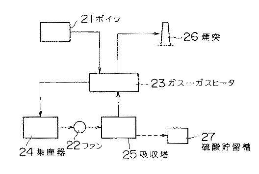
図2は、本発明の排煙脱硫装置を含む脱硫システムの一例である。以下の図2の説明中の温度条件等の数値は、典型的な例を示すものである。
図2において、ボイラ21から排出されたSO2 を含有する排ガス(温度:360℃、SO2 濃度:1000ppm、水分:8.4容量%)は、ガス−ガスヒータ(GGH)23によって冷却された後、集塵器(ESP)24内で除塵され、ファン22を経由して、吸収塔25内に導入される。導入された排ガスは、増湿冷却されて温度が30℃、相対湿度100%となった後、吸収塔25内に設けられた脱硫反応用活性炭素繊維層で脱硫されて、SO2 濃度が50ppm未満となり、吸収塔25から排出される。脱硫された排ガスは、ガス−ガスヒータ23で加熱された後、煙突26から排出される。排煙脱硫装置の稼動を止めて、生成した硫酸を回収するときは、吸収塔の底部から硫酸をポンプで硫酸貯留槽27に導けばよい。
【0018】
【発明の効果】
本発明の排煙脱硫装置によれば、脱硫反応用活性炭素繊維上で生成した希硫酸を回収して、排ガスの増湿冷却用水または脱硫用水として用いるので、外部からの水の供給量が少なくても、排ガスを充分に増湿冷却したり、脱硫反応用活性炭素繊維層に充分に水を供給することができる。特に、脱硫反応用活性炭素繊維層への充分な水の供給は、脱硫率を高めることに寄与する。
【図面の簡単な説明】
【図1】本発明の排煙脱硫装置の縦断面を示す概略図である。
【図2】本発明の排煙脱硫装置を含む脱硫システムの一例である。
【符号の説明】
1 吸収塔
2 導入口
3 水の散布器
4 活性炭素繊維層
5 水の供給器
6 希硫酸
7 ポンプ
8 循環ライン
9 排出口
21 ボイラ
22 ファン
23 ガス−ガスヒータ
24 集塵器
25 吸収塔
26 煙突
27 硫酸貯留槽[0001]
BACKGROUND OF THE INVENTION
The present invention relates to a flue gas desulfurization apparatus for removing sulfur oxides (SO x ) in exhaust gas discharged from boilers, gas turbines, engines, combustion furnaces and the like that burn various fuels.
[0002]
[Prior art]
Conventionally, as a method for removing sulfur oxides in exhaust gas, a lime-gypsum method is used in which limestone or slaked lime slurry is used as an absorbent and the sulfur content is recovered as gypsum.
As another method, an adsorption method using activated carbon is known.
[0003]
[Problems to be solved by the invention]
Conventional lime-gypsum methods require large amounts of water and sulfur oxide absorbents. For this reason, an increase in size and complexity of the desulfurization facility is inevitable.
Further, in the case of the adsorption method using activated carbon, a large amount of water is required in order to desorb the sulfur component adsorbed on the activated carbon by washing with water. Moreover, in this method, it is necessary to discard the produced dilute sulfuric acid, dry the adsorbent, and the like.
An object of the present invention is to provide a flue gas desulfurization apparatus that does not require a sulfur oxide absorbent or a large-scale desulfurization facility and that requires a small amount of water for desulfurization.
[0004]
The flue gas desulfurization apparatus of the present invention includes an absorption tower having an introduction port and an exhaust port for exhaust gas containing sulfur oxide, an activated carbon fiber layer for desulfurization reaction provided in the absorption tower, and an activity for the desulfurization reaction. An exhaust gas humidifier cooling water sprayer provided on the upstream side of the carbon fiber layer, and a desulfurization water supply device to the activated carbon fiber layer for the desulfurization reaction, and sprayed in the absorption tower The humidified cooling water and / or the desulfurization water is stored as sulfuric acid at the bottom of the absorption tower, and the stored sulfuric acid is recovered and provided with a circulation line so that it can be repeatedly used by circulation. In the spreader, as the humidified cooling water, both or any of sulfuric acid which is all or part of sulfuric acid stored at the bottom of the absorption tower and circulated from the circulation line and external dilution water is used. Can supply one or the other To, the above-mentioned feeder, as the desulfurization water, or both of the sulfuric acid is circulated from the circulation line comprising all or part of the sulfuric acid stored in the bottom of the absorption tower, and the dilution water from the outside Any one of them can be supplied (Claim 1).
[0005]
DETAILED DESCRIPTION OF THE INVENTION
The flue gas desulfurization apparatus of the present invention includes an absorption tower having an exhaust gas inlet and an exhaust port, and an activated carbon fiber layer for desulfurization reaction in which the exhaust gas passes through and desulfurizes is provided inside the absorption tower. .
In the present invention, the gas to be desulfurized is a gas containing sulfur dioxide (SO 2 ). The SO 2 concentration is arbitrary, but when it is about 200 to 1,000 ppm in particular, it can be more efficiently desulfurized.
[0006]
Further, since oxygen (O 2 ) is used to oxidize SO 2 to SO 3 at the time of desulfurization, it is necessary to contain oxygen in the exhaust gas or to separately supply oxygen into the exhaust gas. The lower limit of the oxygen content in the exhaust gas is preferably 2% by volume or more, and preferably 3 to 21% by volume, in order to cause the desired desulfurization reaction. That is, oxygen is required for the oxidation of SO 2 , and the higher the oxygen concentration, the better.
As gas components other than SO 2 and O 2 , components such as nitrogen, carbon dioxide and carbon monoxide can be usually contained.
The gas flow rate is usually about 1 × 10 −3 to 5 × 10 −5 g · min / ml per unit weight of the activated carbon fiber for desulfurization reaction.
[0007]
The activated carbon fiber for desulfurization reaction used in the present invention functions as a catalyst when SO 2 in exhaust gas is oxidized to SO 3 .
A method for producing the activated carbon fiber for desulfurization reaction will be described below.
There is no restriction | limiting in particular as a kind of activated carbon fiber used as a raw material, Activated carbon fibers, such as a pitch type, a polyacrylonitrile type, a phenol type, a cellulose type, can be used. Among these, those having higher hydrophobicity on the surface of activated carbon fibers are particularly desirable, and specific examples include pitch-based activated carbon fibers.
[0008]
Activated carbon fibers are usually heat-treated at a temperature of about 600 to 1,200 ° C. in a non-oxidizing atmosphere such as nitrogen gas. The treatment time may be appropriately determined according to the treatment temperature or the like. By this heat treatment, the carbon fiber for desulfurization reaction used in the present invention can be obtained. The activated carbon fiber for desulfurization reaction has a surface having a larger hydrophobicity than before the treatment because part or all of the hydrophilic oxygen functional group is removed as CO, CO 2 or the like by heat treatment. Therefore, it occurs readily snapping SO 2 to oxidized active sites SO 2, yet produced results that discharge also proceeds rapidly sulfate, without the function of the catalyst is inhibited, the desulfurization reaction is accelerated.
[0009]
The specific example of the manufacture example of the activated carbon fiber for desulfurization reaction is as follows, for example.
Example 1
A pitch-based activated carbon fiber (“OG-20A”, manufactured by Adol Co., Ltd.) is used, and this is fired in a nitrogen atmosphere within a temperature range of 900 to 1,200 ° C. for 1 hour.
Example 2
Polyacrylonitrile-based activated carbon fiber (“FE-300”, manufactured by Toho Rayon Co., Ltd.) is used, and this is fired in a nitrogen atmosphere within a temperature range of 800 to 1,200 ° C. for 1 hour.
[0010]
Properties of desulfurization for the active carbon fiber used in the present invention, generally the thickness is 7~20Myuemu, specific surface area of 500~2,500m 2 / g, the outer surface area of 0.2~2.0m 2 / g, The pore diameter is 45 angstroms or less.
Table 1 shows the compositional formulas and the like of activated carbon fibers for each desulfurization reaction of pitch, polyacrylonitrile, phenol and cellulose. In addition, the numerical value in Table 1 only shows a normal value, and the thing outside these numerical ranges may exist.
[0011]
[Table 1]
Hereinafter, an example of an embodiment using the present invention will be described with reference to FIG.
In FIG. 1, exhaust gas containing sulfur oxides discharged from a boiler is introduced into the absorption tower 1 from an inlet 2 at the top of the absorption tower 1. The exhaust gas introduced into the absorption tower 1 is cooled to 70 ° C. or less, preferably 20 to 60 ° C., more preferably about 30 to 55 ° C. by the water sprayed from the sprayer 3 for humidifying and cooling the exhaust gas. In addition, the relative humidity increases and is usually saturated (relative humidity = 100%).
Here, if the temperature of the exhaust gas does not fall below 70 ° C., the amount of water evaporation in the activated carbon fiber layer 4 for desulfurization reaction increases, and the efficiency of the desulfurization reaction decreases. Further, if the relative humidity is about 60% or more, desulfurization reaction occurs in the activated carbon fiber layer 4 for desulfurization reaction, but in order to obtain a good desulfurization rate, the relative humidity is 100% (saturated state). Is preferred.
The installation position of the water disperser 3 for humidification cooling is to disperse water on the upstream side of the activated carbon fiber layer 4 for desulfurization reaction, that is, the exhaust gas before passing through the activated carbon fiber layer 4 for desulfurization reaction. Any position that can be used.
[0013]
The exhaust gas that has been humidified and cooled passes downward through the activated carbon fiber layer 4 for desulfurization reaction that is filled in the central portion of the absorption tower 1. In addition, water is supplied to the activated carbon fiber layer 4 for desulfurization reaction in advance by a desulfurization water supply device 5 provided above or in the vicinity of the activated carbon fiber layer 4 for desulfurization reaction. Leave it attached.
[0014]
When the exhaust gas passes downward through the activated carbon fiber layer 4 for desulfurization reaction, SO 2 in the exhaust gas is oxidized to SO 3 on the surface of the activated carbon fiber. The produced SO 3 reacts with water adhering to the activated carbon fiber to become sulfuric acid (H 2 SO 4 ). The produced sulfuric acid 6 falls from the activated carbon fiber layer 4 for desulfurization reaction, is discharged from the bottom of the absorption tower, is stored in a sulfuric acid storage tank (not shown) through the pump 7, and is used for industrial use.
The concentration of the obtained sulfuric acid is 20% or more for industrial use, and preferably 50% or more for convenience of distribution.
[0015]
All or part of the sulfuric acid stored at the bottom of the absorption tower 1 is supplied to the exhaust gas humidified cooling water sprayer 3 and / or the desulfurized water supply device 5 by a circulation line (circulation pipe) 8 or one of them. Led to and used repeatedly. As a result, the amount of water supplied from the outside can be greatly reduced.
In addition, as shown in FIG. 1, the diffuser 3 for exhaust gas humidified cooling water includes either or both of the above-mentioned humidified cooling water from the circulation line and external dilution water. As shown in FIG. 1, the desulfurization water supply unit 5 can supply either one of such a desulfurization water and a dilution water from the outside or any one of them. One of them can be supplied.
The desulfurized exhaust gas after passing through the activated carbon fiber layer 4 for desulfurization reaction is discharged from the discharge port 9 of the absorption tower 1.
[0016]
Although FIG. 1 shows a case where there is one humidifier cooling water sprayer, other modes may be employed. For example, a plurality of humidifier cooling water sprayers may be installed in the vertical direction. In addition to spraying the humidified cooling water for spraying the circulating water supplied through the circulation line 8, for spraying water (dilution water) introduced from the outside above or below the sprayer. The humidifier cooling water sprayer may be installed separately.
Similarly, a plurality of desulfurization water supply units may be provided, or a desulfurization water supply unit for supplying water introduced from the outside (dilution water) may be provided separately.
The humidifier cooling water sprayer and the desulfurization water feeder may be used in combination.
The concentration of the dilute sulfuric acid produced can be adjusted by adjusting the ratio between the circulating water and the external dilution water.
[0017]
FIG. 2 is an example of a desulfurization system including the flue gas desulfurization apparatus of the present invention. Numerical values such as temperature conditions in the following description of FIG. 2 show typical examples.
In FIG. 2, the exhaust gas containing SO 2 discharged from the boiler 21 (temperature: 360 ° C., SO 2 concentration: 1000 ppm, moisture: 8.4 vol%) is cooled by a gas-gas heater (GGH) 23. The dust is removed in a dust collector (ESP) 24 and introduced into the absorption tower 25 via the fan 22. The introduced exhaust gas is humidified and cooled to a temperature of 30 ° C. and a relative humidity of 100%, and then desulfurized by the activated carbon fiber layer for desulfurization reaction provided in the absorption tower 25, so that the SO 2 concentration is 50 ppm. And is discharged from the absorption tower 25. The desulfurized exhaust gas is heated by the gas-gas heater 23 and then discharged from the chimney 26. When the operation of the flue gas desulfurization apparatus is stopped and the generated sulfuric acid is recovered, the sulfuric acid may be led from the bottom of the absorption tower to the sulfuric acid storage tank 27 by a pump.
[0018]
【The invention's effect】
According to the flue gas desulfurization apparatus of the present invention, the dilute sulfuric acid generated on the activated carbon fiber for the desulfurization reaction is recovered and used as the moisture for cooling and desulfurization of exhaust gas, so that the amount of water supplied from the outside is small. However, the exhaust gas can be sufficiently humidified and cooled, or water can be sufficiently supplied to the activated carbon fiber layer for desulfurization reaction. In particular, sufficient water supply to the activated carbon fiber layer for desulfurization reaction contributes to increasing the desulfurization rate.
[Brief description of the drawings]
FIG. 1 is a schematic view showing a longitudinal section of a flue gas desulfurization apparatus of the present invention.
FIG. 2 is an example of a desulfurization system including the flue gas desulfurization apparatus of the present invention.
[Explanation of symbols]
DESCRIPTION OF SYMBOLS 1 Absorption tower 2 Inlet 3 Water sprinkler 4 Activated carbon fiber layer 5 Water supply 6 Dilute sulfuric acid 7 Pump 8 Circulation line 9 Outlet 21 Boiler 22 Fan 23 Gas-gas heater 24 Dust collector 25 Absorption tower 26 Chimney 27 Sulfuric acid storage tank
Claims (1)
Priority Applications (1)
| Application Number | Priority Date | Filing Date | Title |
|---|---|---|---|
| JP16037798A JP3659802B2 (en) | 1998-06-09 | 1998-06-09 | Flue gas desulfurization equipment |
Applications Claiming Priority (1)
| Application Number | Priority Date | Filing Date | Title |
|---|---|---|---|
| JP16037798A JP3659802B2 (en) | 1998-06-09 | 1998-06-09 | Flue gas desulfurization equipment |
Publications (2)
| Publication Number | Publication Date |
|---|---|
| JPH11347364A JPH11347364A (en) | 1999-12-21 |
| JP3659802B2 true JP3659802B2 (en) | 2005-06-15 |
Family
ID=15713659
Family Applications (1)
| Application Number | Title | Priority Date | Filing Date |
|---|---|---|---|
| JP16037798A Expired - Fee Related JP3659802B2 (en) | 1998-06-09 | 1998-06-09 | Flue gas desulfurization equipment |
Country Status (1)
| Country | Link |
|---|---|
| JP (1) | JP3659802B2 (en) |
Families Citing this family (3)
| Publication number | Priority date | Publication date | Assignee | Title |
|---|---|---|---|---|
| JP4574884B2 (en) * | 2001-03-27 | 2010-11-04 | 住友重機械工業株式会社 | Method and apparatus for recovering sulfuric acid in exhaust gas treatment system |
| US7267710B2 (en) | 2003-03-28 | 2007-09-11 | Mitsubishi Heavy Industries, Ltd. | Method of and apparatus for regenerating adsorbent |
| US9848513B2 (en) | 2010-07-09 | 2017-12-19 | Hewlett Packard Enterprise Development Lp | Cooling systems and methods |
-
1998
- 1998-06-09 JP JP16037798A patent/JP3659802B2/en not_active Expired - Fee Related
Also Published As
| Publication number | Publication date |
|---|---|
| JPH11347364A (en) | 1999-12-21 |
Similar Documents
| Publication | Publication Date | Title |
|---|---|---|
| EP1834689A3 (en) | Flue gas desulfurizatuin apparatus, flue gas desulfurization system, and method for operating flue gas desulfurization apparatus | |
| CN110152478A (en) | A kind of flue gas wet denitration system and method based on the preposition oxidation of physical absorption | |
| JP3860912B2 (en) | Flue gas desulfurization equipment | |
| JP3790369B2 (en) | Flue gas desulfurization equipment | |
| JP3860911B2 (en) | Flue gas desulfurization method and apparatus | |
| CN210522213U (en) | Flue gas desulfurization and denitrification device | |
| JP2005028216A (en) | Gas cleaning apparatus and flue gas desulfurization system | |
| JP3659802B2 (en) | Flue gas desulfurization equipment | |
| CN208082183U (en) | A kind of kiln gas minimum discharge controlling device | |
| WO2005054126A1 (en) | Carbon material and flue gas treatment apparatus | |
| JP3513390B2 (en) | Flue gas desulfurization equipment | |
| JP2004066009A (en) | Carbon material and equipment for treating flue gas | |
| JP3600441B2 (en) | Catalyst board for flue gas desulfurization | |
| JP3790368B2 (en) | Exhaust gas purification method | |
| CN209188468U (en) | A kind of high efficient cryogenic desulphurization denitration tower | |
| JP2009149460A (en) | Surface modification method of carbonaceous material, and carbonaceous material or activated carbon fiber | |
| CN209287047U (en) | Equipment for denitrifying flue gas | |
| JP4719117B2 (en) | Exhaust gas treatment method | |
| CN204338021U (en) | Secondary SCR catalytic oxidizing equipment | |
| JP2004337776A (en) | Exhaust gas treating apparatus | |
| JP2006104598A (en) | Activated carbon fiber, method for producing the same and gas purification method | |
| JP2008136982A (en) | Carbon-based catalyst for flue-gas desulfurization and its manufacturing method | |
| CN110394056A (en) | A kind of Industrial Boiler flue gas dehumidifying system for desulfuration and denitration and method | |
| CN205925418U (en) | High -efficient desulfurization of flue gas is dust collector in coordination | |
| CN206262347U (en) | A kind of semi-dry desulphurization tower for being provided with flue gas self-loopa adjusting means |
Legal Events
| Date | Code | Title | Description |
|---|---|---|---|
| A977 | Report on retrieval |
Free format text: JAPANESE INTERMEDIATE CODE: A971007 Effective date: 20040427 |
|
| A131 | Notification of reasons for refusal |
Free format text: JAPANESE INTERMEDIATE CODE: A131 Effective date: 20040507 |
|
| A521 | Written amendment |
Free format text: JAPANESE INTERMEDIATE CODE: A523 Effective date: 20040706 |
|
| A131 | Notification of reasons for refusal |
Free format text: JAPANESE INTERMEDIATE CODE: A131 Effective date: 20040903 |
|
| A521 | Written amendment |
Free format text: JAPANESE INTERMEDIATE CODE: A523 Effective date: 20041027 |
|
| TRDD | Decision of grant or rejection written | ||
| A01 | Written decision to grant a patent or to grant a registration (utility model) |
Free format text: JAPANESE INTERMEDIATE CODE: A01 Effective date: 20050218 |
|
| A61 | First payment of annual fees (during grant procedure) |
Free format text: JAPANESE INTERMEDIATE CODE: A61 Effective date: 20050315 |
|
| R150 | Certificate of patent or registration of utility model |
Free format text: JAPANESE INTERMEDIATE CODE: R150 |
|
| FPAY | Renewal fee payment (event date is renewal date of database) |
Free format text: PAYMENT UNTIL: 20080325 Year of fee payment: 3 |
|
| FPAY | Renewal fee payment (event date is renewal date of database) |
Free format text: PAYMENT UNTIL: 20090325 Year of fee payment: 4 |
|
| FPAY | Renewal fee payment (event date is renewal date of database) |
Free format text: PAYMENT UNTIL: 20100325 Year of fee payment: 5 |
|
| FPAY | Renewal fee payment (event date is renewal date of database) |
Free format text: PAYMENT UNTIL: 20110325 Year of fee payment: 6 |
|
| FPAY | Renewal fee payment (event date is renewal date of database) |
Free format text: PAYMENT UNTIL: 20110325 Year of fee payment: 6 |
|
| FPAY | Renewal fee payment (event date is renewal date of database) |
Free format text: PAYMENT UNTIL: 20120325 Year of fee payment: 7 |
|
| FPAY | Renewal fee payment (event date is renewal date of database) |
Free format text: PAYMENT UNTIL: 20130325 Year of fee payment: 8 |
|
| FPAY | Renewal fee payment (event date is renewal date of database) |
Free format text: PAYMENT UNTIL: 20130325 Year of fee payment: 8 |
|
| S111 | Request for change of ownership or part of ownership |
Free format text: JAPANESE INTERMEDIATE CODE: R313117 |
|
| FPAY | Renewal fee payment (event date is renewal date of database) |
Free format text: PAYMENT UNTIL: 20130325 Year of fee payment: 8 |
|
| R350 | Written notification of registration of transfer |
Free format text: JAPANESE INTERMEDIATE CODE: R350 |
|
| FPAY | Renewal fee payment (event date is renewal date of database) |
Free format text: PAYMENT UNTIL: 20130325 Year of fee payment: 8 |
|
| LAPS | Cancellation because of no payment of annual fees |