JP3658963B2 - Automatic transmission tie-up determination device and shift control device using the same - Google Patents
Automatic transmission tie-up determination device and shift control device using the same Download PDFInfo
- Publication number
- JP3658963B2 JP3658963B2 JP00532198A JP532198A JP3658963B2 JP 3658963 B2 JP3658963 B2 JP 3658963B2 JP 00532198 A JP00532198 A JP 00532198A JP 532198 A JP532198 A JP 532198A JP 3658963 B2 JP3658963 B2 JP 3658963B2
- Authority
- JP
- Japan
- Prior art keywords
- tie
- clutch
- automatic transmission
- output shaft
- determination
- Prior art date
- Legal status (The legal status is an assumption and is not a legal conclusion. Google has not performed a legal analysis and makes no representation as to the accuracy of the status listed.)
- Expired - Fee Related
Links
Images


Classifications
-
- F—MECHANICAL ENGINEERING; LIGHTING; HEATING; WEAPONS; BLASTING
- F16—ENGINEERING ELEMENTS AND UNITS; GENERAL MEASURES FOR PRODUCING AND MAINTAINING EFFECTIVE FUNCTIONING OF MACHINES OR INSTALLATIONS; THERMAL INSULATION IN GENERAL
- F16H—GEARING
- F16H61/00—Control functions within control units of change-speed- or reversing-gearings for conveying rotary motion ; Control of exclusively fluid gearing, friction gearing, gearings with endless flexible members or other particular types of gearing
- F16H61/04—Smoothing ratio shift
- F16H61/06—Smoothing ratio shift by controlling rate of change of fluid pressure
- F16H61/061—Smoothing ratio shift by controlling rate of change of fluid pressure using electric control means
-
- F—MECHANICAL ENGINEERING; LIGHTING; HEATING; WEAPONS; BLASTING
- F16—ENGINEERING ELEMENTS AND UNITS; GENERAL MEASURES FOR PRODUCING AND MAINTAINING EFFECTIVE FUNCTIONING OF MACHINES OR INSTALLATIONS; THERMAL INSULATION IN GENERAL
- F16H—GEARING
- F16H61/00—Control functions within control units of change-speed- or reversing-gearings for conveying rotary motion ; Control of exclusively fluid gearing, friction gearing, gearings with endless flexible members or other particular types of gearing
- F16H2061/0075—Control functions within control units of change-speed- or reversing-gearings for conveying rotary motion ; Control of exclusively fluid gearing, friction gearing, gearings with endless flexible members or other particular types of gearing characterised by a particular control method
- F16H2061/0087—Adaptive control, e.g. the control parameters adapted by learning
-
- F—MECHANICAL ENGINEERING; LIGHTING; HEATING; WEAPONS; BLASTING
- F16—ENGINEERING ELEMENTS AND UNITS; GENERAL MEASURES FOR PRODUCING AND MAINTAINING EFFECTIVE FUNCTIONING OF MACHINES OR INSTALLATIONS; THERMAL INSULATION IN GENERAL
- F16H—GEARING
- F16H59/00—Control inputs to control units of change-speed-, or reversing-gearings for conveying rotary motion
- F16H59/60—Inputs being a function of ambient conditions
- F16H59/66—Road conditions, e.g. slope, slippery
Description
【0001】
【発明の属する技術分野】
本発明は、係合側クラッチの係合と解放側クラッチの解放の進行とを同時に行うクラッチツウクラッチ変速を実行する際に、前記解放側クラッチの解放より前記係合側クラッチの係合の進行の方が相対的に速すぎるタイアップが発生したか否かを判定する自動変速機のタイアップ判定装置、及びこれを用いた変速制御装置に関する。
【0002】
【従来の技術】
自動変速機の特定の変速を実行する場合に、2つの摩擦係合装置(広義のクラッチ;ブレーキを含む)の係合と解放とを同時に行わなければならないことがよくある(いわゆるクラッチツウクラッチ変速)。この場合、各摩擦係合装置の係合の進行と解放の進行との同期を適確にとらないと、出力軸トルクが落ち込んだり、エンジンが吹き上がったりする。
【0003】
このため、従来はこのような制御を行わせる場合には、一般に、一方の摩擦係合装置の機能と実質的に同等な機能を果たす一方向クラッチを設け、こうした不具合が発生しないように配慮していた。
【0004】
しかしながら、このように一方向クラッチを用いることによって各摩擦係合装置の同期をとる方法は、当該一方向クラッチを付設する分コストが上昇し、又、重量が増大したり収容スペースを占める等の問題が発生する。
【0005】
このような点に鑑み、近年、各種センサ技術の向上、油圧制御装置の電子制御技術の向上を背景として、一方向クラッチを用いることなく「クラッチツウクラッチ変速」を直接実行させるようにする試みが再び活発化している。
【0006】
特開平2−37128号公報においては、このような現状に鑑み、変速動作時のエンジン回転速度をモニタし、該エンジン回転速度が吹き上がったときに(エンジン回転速度が上昇したときに)、各摩擦係合装置がアンダーラップ状態となった(解放の進行に対して係合の進行が相対的に遅れている状態となった)と認識し、一方、エンジン回転速度が低下したときに各摩擦係合装置がオーバーラップ状態となった(解放の進行に対して係合の進行が相対的に早すぎる状態となった:以降、この状態をタイアップ状態と称す)と認識する方法が開示されている。
【0007】
又、特開平6−341527号公報においては、このタイアップ状態を判定する方法として、トルク相開始からイナーシャ相開始までの時間を検出して、この時間が長いときにはタイアップと判定することが開示されている。
【0008】
【発明が解決しようとする課題】
しかしながら、このような判定方法では、エンジン吹きについては比較的容易に検出できるものの、タイアップの判定については、非常に長い(あるいは強い)タイアップの発生しか判定できず、即ち、判定精度は極めて悪く、更には、当然の如くタイアップ状態におけるその度合いを正確に把握することなどはできないので、フィードバック制御や学習制御を実施する上で、適確に制御することは、非常に困難であった。特に、学習制御を行う上で、クラッチ減圧・増圧タイミングを最適にするために学習補正を用いた場合には、タイアップ状態の解消方向への学習ゲインが最適化できず、学習初期でのタイアップ状態の解消の遅れ、あるいは学習が進んだ状態でのハンチング(スリップ状態とタイアップ状態の繰返し)等の問題が発生し易かった。
【0009】
更に、タイアップ状態が発生すると、出力軸トルクが急激に落ち込み、強い変速ショックが発生すると共に、場合によっては自動変速機の各部材に非常に大きな負荷トルクがかかり、耐久性が低下する要因になっている。
【0010】
本発明は、このような従来の問題に鑑みてなされたものであって、クラッチツウクラッチ変速におけるタイアップを早期に、且つ的確に判定し、更にそのタイアップ状態又はスリップ状態の度合いを検出しながら、変速に係わる2つのクラッチの減圧・増圧タイミングを学習又は即時補正(フィードバック制御)をして最適タイミングを実現することを可能にする。
【0011】
その結果、有効な油圧補正制御を実行して変速ショックを低減すると共に、自動変速機の各部材に過度の負荷トルクがかかるのを防止し、耐久性をより向上させ、スムーズな変速を実現することを、その目的としている。
【0012】
【課題を解決するための手段】
請求項1に記載の発明は、係合側クラッチの係合と解放側クラッチの解放とを同時に行うクラッチツウクラッチ変速を実行する際に、前記解放側クラッチの解放の進行より前記係合側クラッチの係合に進行の方が相対的に速すぎるタイアップが発生したか否かを判定する自動変速機のタイアップ判定装置において、変速指令から、イナーシャ相開始後所定時間が経過するまでの判定時間を確定する手段と、該判定期間における時々刻々と変化する自動変速機の出力軸回転速度から得られる、該出力軸回転速度の変動量を求める手段と、該変動量に基づいてタイアップの度合いを判定する手段と、を備えたことにより、上記目的を達成したものである。
【0013】
請求項2に記載の発明は、係合側クラッチの係合と解放側クラッチの解放とを同時に行うクラッチツウクラッチ変速を実行する際に、前記解放側クラッチの解放の進行より前記係合側クラッチの係合に進行の方が相対的に速すぎるタイアップが発生したか否かを判定する自動変速機のタイアップ判定装置において、変速指令から、イナーシャ相開始後入力軸回転速度が低速段同期回転速度から所定量降下するまでの判定期間を確定する手段と、該判定期間における時々刻々と変化する自動変速機の出力軸回転速度から得られる該出力軸回転速度の変動量を求める手段と、該変動量に基づいてタイアップの度合いを判定する手段と、を備えたことにより、同じく上記目的を達成したものである。
【0014】
なお、出力軸回転速度の変動量は前記判定期間中における平均加速度と時々刻々の加速度の差の絶対値を時間積分することによって求めるとよい。
【0015】
判定期間中の平均加速度としては、所定時間内の平均加速度を用いるとよい。
【0016】
あるいは、出力軸回転速度の変動量を、出力軸回転速度の変動の最大振幅を演算することによって求めてもよい。
【0017】
更には、車両が走行している路面が悪路か否かを判定する手段を備え、該悪路走行判定手段により、悪路走行中でないと判定されているときのみ、前記タイアップの判定を実行するようにしてもよい。このようにすることにより走行中の振動によってセンサ系が誤動作し、不適正なタイアップ判定をしてしまうのを防止できる。
【0018】
又、入力軸回転速度あるいは出力軸回転速度を検出するセンサが、正常であるか否かを判定する手段を備え、正常であると判定されたときのみ、前記タイアップ判定を実行するようにしてもよい。同様にセンサ系の誤動作による不適正なタイアップ判定をする恐れがそれだけ少なくなる。
【0019】
このようにして検出されたタイアップの度合いに応じて解放側又は係合側の少なくとも一方のクラッチのクラッチ圧を補正・制御するようにすれば、係合側クラッチと解放側クラッチの増・減圧のタイミングを最適化でき、更に精度の良い補正制御、学習制御が可能となり、スムーズな変速ができる。
【0020】
【発明の実施の形態】
以下、図面を参照して本発明の実施形態を詳細に説明する。
【0021】
以下に説明する実施形態は、係合側クラッチの係合と解放側クラッチの解放とを同時に行うクラッチツウクラッチ変速を実行する際に、解放側クラッチの解放の進行より係合側クラッチの係合の進行の方が相対的に速すぎる(いわゆるタイアップ)状態が発生したか否かを判定する自動変速機のタイアップ制御装置に関する。
【0022】
図8は、本発明の実施形態に係る自動変速機のタイアップ判定装置のスケルトン図である。この自動変速機2は、トルクコンバータ111、副変速部112及び主変速部113を備える。
【0023】
なお、本発明の適用対象はこのような自動変速機に限定されず、例えばツインクラッチ式の自動変速機にも適用可能である。
【0024】
前記トルクコンバータ111は、ロックアップクラッチ124を備える。このロックアップクラッチ124は、ポンプインペラ126に一体化させてあるフロントカバー127とタービンランナ128を一体に取付けた部材(ハブ)129との間に設けられている。
【0025】
エンジン1のクランクシャフト(図示せず)はフロントカバー127に連結されている。タービンランナ128に連結された入力軸130は、副変速部112を構成するオーバードライブ用遊星歯車機構131のキャリヤ132に連結されている。
【0026】
この遊星歯車機構131におけるキャリヤ132とサンギヤ133との間には、クラッチC0 と一方向クラッチF0 とが設けられている。この一方向クラッチF0 はサンギヤ133がキャリヤ132に対して相対的に正回転(入力軸130の回転方向の回転)する場合に係合するようになっている。
【0027】
一方、サンギヤ133の回転を選択的に止めるブレーキB0 が設けられている。又、この副変速部112の出力要素であるリングギヤ134が、主変速部113の入力要素である中間軸135に接続されている。
【0028】
副変速部112は、クラッチC0 もしくは一方向クラッチF0 が係合した状態では遊星歯車機構131の全体が一体となって回転するため、中間軸135が入力軸130と同速度で回転する。又ブレーキB0 を係合させてサンギヤ133の回転を止めた状態では、リングギヤ134が入力軸130に対して増速されて正回転する。即ち、副変速部112はハイ・ローの2段の切換えを設定することができる。
【0029】
前記主変速部113は三組の遊星歯車機構140、150、160を備えており、これらの歯車機構140、150、160が以下のように連結されている。
【0030】
即ち、第1遊星歯車機構140のサンギヤ141と第2遊星歯車機構150のサンギヤ151とが互いに一体的に連結され、第1遊星歯車機構140のリングギヤ143と第2遊星歯車機構150のキャリヤ152と第3遊星歯車機構160のキャリヤ162との三者が連結されている。又、第3遊星歯車機構160のキャリヤ162に出力軸170が連結されている。更に第2遊星歯車機構150のリングギヤ153が第3遊星歯車機構160のサンギヤ161に連結されている。
【0031】
この主変速部113の歯車列では後進1段と前進4段とを設定することができ、そのためのクラッチ及びブレーキが以下のように設けられている。
【0032】
即ち、第2遊星歯車機構150のリングギヤ153及び第3遊星歯車機構160のサンギヤ161と中間軸135との間にクラッチC1 が設けられ、又第1遊星歯車機構140のサンギヤ141及び第2遊星歯車機構150のサンギヤ151と中間軸135との間にクラッチC2 が設けられている。
【0033】
第1遊星歯車機構140及び第2遊星歯車機構150のサンギヤ141、151の回転を止めるブレーキB1 が配置されている。又、これらのサンギヤ141、151とケーシング171との間には、一方向クラッチF1 とブレーキB2 とが直列に配列されている。一方向クラッチF1 はサンギヤ141、151が逆回転(入力軸135の回転方向とは反対方向の回転)しようとする際に係合するようになっている。
【0034】
第1遊星歯車機構140のキャリヤ142とケーシング171との間にはブレーキB3 が設けられている。又、第3遊星歯車機構160のリングギヤ163の回転をとめる要素としてブレーキB4 と、一方向クラッチF2 とがケーシング171との間に並列に配置されている。なお、この一方向クラッチF2 はリングギヤ163が逆回転しようとする際に係合するようになっている。
【0035】
上記の自動変速機2では、全体で後進1段と前進5段の変速を行うことができる。これらの変速段を設定するための各クラッチ及びブレーキの係合作動表を図9に示す。なお、図9において、○印は係合状態、●印はエンジンブレーキ時に係合状態、空欄は解放状態をそれぞれ示す。
【0036】
この図から明らかなように、第2速段及び第3速段間の変速がブレーキB2 と、ブレーキB3 のクラッチツウクラッチ変速となっていることが分かる。
【0037】
各クラッチ及びブレーキの係合あるいは解放は、油圧制御装置(油圧制御手段)20内の電磁弁やリニアソレノイドが、コンピュータ30からの指令に基づいて駆動されることによって実行される。コンピュータ30には、各種センサ群40からの信号、例えば車速センサ41からの車速信号(出力軸回転速度N0 の信号)、スロットルセンサ42からのスロットル開度信号(アクセル開度信号)、パターンセレクトスイッチ43からのパターンセレクト信号(運転者の選択した動力重視走行、燃費重視走行等の選択信号)、シフトポジションスイッチ44からのシフトポジション信号、ブレーキスイッチ45からのフットブレーキ信号等の基本的な信号の他、C0 センサ46からのクラッチC0 の回転速度信号が入力されている。クラッチC0 の回転速度は第2速段及び第3速段間の変速時にはタービン回転速度(自動変速機の入力軸回転速度)Nt と同一になるため、該クラッチC0 の回転速度を検出することによりタービン回転速度Nt を把握することができる。
【0038】
なお、ブレーキB2 及びB3 の変速の時の油圧制御自体については各種方法が従来公知であるため、ここでは詳細な説明は省略するが、基本的には、ブレーキB2 及びブレーキB3 とも、その油路中に設けられているアキュムレータの背圧をアクチュエータコントロールバルブ及びこれを制御するリニアソレノイドによって制御してやればよい。あるいは、その油路中の油圧を直接的にデューティソレノイド等で制御してもよい。なお、解放側については、油圧を低下させる制御であるため、当該油圧回路のドレン量をリニアソレノイドやデューティソレノイドによって制御してやってもよい。
【0039】
図1は、クラッチツウクラッチ変速のアップシフトにおける解放側クラッチの解放の進行より係合側クラッチの係合の進行の方が相対的に速くなり、いわゆるタイアップ状態となったことを検出する際の各種特性を表した図である。
【0040】
ここではパワーオンアップシフトにおける実施形態を示すので、係合側クラッチは高速段側クラッチとなり、解放側クラッチは低速段側クラッチとなる。
【0041】
時刻t0 において、このアップシフトを実行すべき走行状態であると判断されると、公知の多重変速を防止するために、若干時間を空けて時刻t1 から低速段側クラッチの油圧を低下させる。低速段側クラッチ油圧は、時刻t2 で一旦、油圧を停止させPlo1に維持させておく。
【0042】
一方、高速段側クラッチは、時刻t3で油圧の上昇を開始させ、時刻t4 で高速段側クラッチが容量を持たない程度のレベルPhi1に一旦維持させておく。但しこの間にクラッチパックが詰められ、高速段側クラッチでは係合の準備が進められる。
【0043】
低速段側クラッチ油圧は時刻t5 から再び低下をさせ、高速段側クラッチ油圧は時刻t6 から同様に再び上昇を開始させる。これにより、低速段側クラッチと高速段側クラッチのつかみ替えが開始するが、このときに、低速段側(開放側)クラッチ油圧の下降(解放)より高速段側(係合側)クラッチの油圧上昇(係合)の方が相対的に速すぎると、2つのクラッチの同時係合による引き摺り状態である、いわゆるタイアップ状態が発生してしまう。
【0044】
本発明では、そのタイアップの度合いを判定することを最大の目的とし、その結果として得られる値を基にして、フィードバック制御や学習制御に利用するようにする。
【0045】
図1のIIで示す部分の拡大図を図2に示す。
【0046】
以下、前述したタイアップの度合いを判定する第1の実施形態を説明する。
【0047】
時刻t6 で高速段側クラッチ油圧を上昇を開始させたとほぼ同時に(図1参照)、出力軸回転速度No も徐々に減少していき、それに応じて出力軸トルクToも減少していく。このときに高速段側クラッチと低速段側クラッチの掴み換えが行われる。
【0048】
低速段側クラッチは、時刻t7 でクラッチ油圧を完全にドレン状態にされる(図1参照)。又、ちょうどそのころ高速段側が全ての入力トルクTinを受け持ち出力軸トルクToは大きく落ち込む。
【0049】
時刻t7 後、高速段側クラッチの係合が進行し、該高速段側クラッチを介して伝達されるトルクがあるレベルを越えると自動変速機内の回転部材がギヤ比変更のための切換え(変速のための回転速度変化)を開始し始め、変速(イナーシャ相)が開始する。各部材が回転速度変化を始めるとそれまで生じていた出力軸トルクToの落ち込みは解消され、以降出力軸には(イナーシャ相が終了するまで)そのときに高速段側クラッチにかけられている油圧に依存したトルクが伝達されるようになる。
【0050】
前述した出力軸トルクToの落ち込みは、ワンウェイクラッチを介した変速の場合にでも、低速段側クラッチで持っていたトルクを高速段側クラッチに移し替えた時点(ワンウェイクラッチが空転を始める時点で)生じるものであり、基本的にはギヤ比の変更分に相当する。つまり、理想的な変速においても変速後のトルクB´(高速段側のギヤ比×入力トルク)に相当するレベルBのところまでは出力軸トルクToは落ち込んでしまう。
【0051】
しかしながら、クラッチツウクラッチの場合において、低速段側クラッチ油圧の低下が遅れ、低速段側クラッチの解放が遅れた場合(いわゆるタイアップ状態)のときは、入力トルクTin<低速段側クラッチのトルク容量+高速段側クラッチのトルク容量となり、余分のトルク容量分が、自動変速機の動力伝達系統をロッキング側に作用させるため、出力軸トルクToがB´以下のB″にまで大きく落ち込むことになってしまう。即ち、クラッチツウクラッチ変速においてタイアップが生じると、そのタイアップの度合に応じ出力トルクToの落ち込みはそれだけ大きくなる。
【0052】
一方、一般に一時的にトルクが落ち込み、これが瞬間的に解消されるとその反動で振動が発生するが、この振動は当該落ち込みが大きいとき程大きくなる傾向がある。従って該出力軸の振動の様子を「出力軸回転速度Noの変動量」として検出すれば結果としてタイアップの程度を定量的に検出できる。
【0053】
本発明はこの知見に基づいて想到されたものであって、該出力軸回転速度Noの変動量を求め、該変動量に基づいてタイアップの度合いを判定する。
【0054】
ここで、出力軸回転速度Noの変動量を求めるにあたって、この実施形態では時々刻々と変化する自動変速機の出力軸回転速度No を時間微分した値である出力軸回転速度変化率(加速度)dNo を求め、又、変速中の平均的な出力軸回転速度変化率(平均加速度)dNo aveを求め、両者の関係を見るようにしている。
【0055】
図2において出力軸回転速度変化率dNo (以後、変化率dNo という)を太線で示し、平均出力軸回転速度変化率dNo ave(以後、平均変化率dNo aveという)を破線で示す。
【0056】
更に、その変化率dNo に基づいてタイアップ状態の度合いを判定するために、変化率dNo と平均変化率dNo aveに基づいて得られる評価量So を次式のようにして求める。
【0057】
評価量So =Σ|dNo −dNo ave|・dt …(1)
【0058】
(1)式は、本発明者がタイアップを評価するために有効な式として見出したもので、平均変化率dNo aveと変化率dNo の差の絶対値を時間で積分したものである。
【0059】
(1)式において、出力軸回転速度No の平均変化率dNo aveは変速指令(時刻t0 )から所定時間の間の変化率dNo の(各)値に基づいて求める。
【0060】
なお、この所定時間は、タイアップ時のトルク低下時間を平均変化率dNo aveに取り込まないようにするため、トルク相開始までの間に設定するとよい。
【0061】
又、積分期間は変速指令(時刻t0 )からイナーシャ相開始時刻t7 の所定時間T1経過後の時刻t9 までの期間(時間T2)とする。なお、これは具体的にはイナーシャ相の開始は時刻t8 で検出されるため、これから所定時間T1′後まで、と同義である。
【0062】
(1)式に基づいて演算した例をグラフにしたのが図2の最下部において評価量So として示したものである。この評価量So が大きければ大きいほどタイアップ状態の度合いが大きいことを意味し、又、逆に評価量So が小さければ小さいほどタイアップ状態が小さいことを意味する。
【0063】
このようにして、タイアップ状態の度合いが、定量的に判定できる評価値So が求まることにより、クラッチのクラッチ油圧を制御するためのフィードバック制御や、学習制御に応用することができる。このことにより、よりきめ細かく精度の良いクラッチツウクラッチ変速が可能となり、よりスムーズな変速が可能となる。
【0064】
次に、タイアップ状態の度合いを判定するための第2の実施形態を説明する。
【0065】
第1の実施形態では、このタイアップ状態の度合いを判定するための検出期間を、前述したように、変速開始指令(時刻t0 )からイナーシャ相開始検出(時刻t8 )から所定時間(T1)経過した時刻t9 までの時間(時間T2)に設定していた。
【0066】
第2の実施形態では、図1に示されるように、タイアップ状態の度合いを判定するための検出期間を、変速開始指令(時刻t0 )から自動変速機の入力軸回転速度No (タービン回転速度)が低速段側同期回転速度から所定量α降下したことが検出される時刻t10までを、タイアップ状態の度合いを検出する期間とする。
【0067】
このようにすることでも第1の実施形態と同様にタイアップを判定するための期間を適正に設定できる。この第2実施形態に係る判定期間の確定は、イナーシャ相の開始自体の検出が不要となる点で優れる。
【0068】
なお、この判定期間の確定は、要はイナーシャ相が開始してから若干の時間が経過した時点が確定されるものであればよく、場合によってはばらつきによっても必ずイナーシャ相が開始する時刻より後に設定されたタイマを変速指令から直接起動する構成を採用してもよい(第1の実施形態の変形)。
【0069】
なお、評価量So の演算に関しては、前記(1)式による演算をそのまま採用できる。即ち、出力軸回転速度No を時間微分した変化率dNo に基づいて、その平均変化率dNo aveと各時刻の変化率dNo の差の絶対値を時間積分した評価量So によってタイアップ状態の度合いを判定すればよい。
【0070】
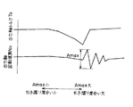
次に、第3の実施形態では、このタイアップ状態の度合いを判定する評価量(出力軸回転速度の変動量)を(1)式の演算によってではなく、図3で示すように、出力軸回転速度No の変動の最大振幅Amax に基づいて(演算して)求めるようにしている。
【0071】
出力軸回転速度No は時々刻々と変化しているので、振幅Aも絶えず変化している。出力軸回転速度No の振幅Aは、振動の大きさを反映しているため出力軸回転速度No の最大振幅Amax を検出することによりタイアップ状態の度合いを算出できる。当然に、出力軸回転速度No の最大振幅Amax が大きいほどタイアップ状態の度合いが大きいことを表している。又、逆に、最大振幅Amax が小さいときほどタイアップ状態ではないことを意味している。
【0072】
このようにして求められたタイアップ(クラッチの引き摺り)状態の度合いは、これをその変速のそれ以降の制御に即反映させてもよいし、次回の変速の反映するように学習制御を行ってもよい。
【0073】
次に、図4を用いて前述した第2実施形態を実施するための制御フローを示す。
【0074】
ステップ100で、自動変速機の入力軸回転速度Ninと出力軸回転速度No を検出(算出)し、ステップ101でその入・出力軸回転速度Nin、No に基づいて変速中か否かを判定し、変速中でないと判定されたならば制御を終了する。又、変速中であることが判定された場合には、ステップ102に進み、アップシフトの指令か否かを判定する。アップシフトの変速でないならば、本発明とは異なるので、他の制御法によりステップ107の変速時のクラッチ油圧が制御される。アップシフトであれば、ステップ103にて低速段同期回転速度(No ×ギヤ比)と自動変速機の入力軸回転速度Ninの差が所定値α以上になったことを判定し、その差が所定値α以上の場合では、ステップ104に進み、クラッチの引き摺り(タイアップ)度合いを前記(1)式に基づいて算出し、ステップ105でその引き摺り度合いに応じ、現在実行中の変速の係合側・解放側クラッチ油圧の増減圧のバランスを変更する。なおこのステップ205を「次回変速のための油圧制御の諸元変更」に置き換えて次回変速を学習制御させる構成としてもよい。
【0075】
又、ステップ103で差が所定値α以下のときは、自動変速機の出力軸回転速度No から得られる変動量を計算し、ステップ107のクラッチ油圧の制御を行う。
【0076】
なお、第1実施形態の制御フローは特に図示はしなかったが、ステップ103におけるクラッチの引き摺り度合いを判定する期間を確定するステップを、「変速指令から、イナーシャ相開始後所定時間経過したかどうか」の判定に変えるだけで、他は同様な制御フローとなる。
【0077】
更に前記第3の実施形態を実行する場合は、ステップ104の出力軸速度No の変動量の演算を(1)式によってではなく、判定期間での最大振幅Amax によって求めるように変更するだけで他は同様の制御フローとなる。
【0078】
ところで、本発明の実施形態を具体的に実施する場合は以下に説明する条件を更に考慮すると一層よい。
【0079】
第1の条件は、車両が走行している路面が悪路(例えば、路面が滑り易い場合)かどうかである。この場合、悪路でないと判定されたときにのみ、本発明における実施形態を実行する。
【0080】
なお、路面が悪路とは、タイヤが滑り易い状態や、滑ってしまっている状態、又は路面の凹凸による振動が車両に伝わる場合等をいう。
【0081】
このような悪路において、本発明を実施しないようにするのは、自動変速機の出力軸回転速度No を検出するのに、タイヤ(車輪)が滑っている状態では、車輪が空回りしているだけで、実際にはアクセルの踏み込み量に対して前進していない状態となるので、出力軸回転速度No の変動量の検出も信頼性がなくなり、変速を実施する際のクラッチのタイアップの判定が適切に行われない場合が発生してしまうからである。又、車両が砂利道等を走行中においても同様のことが発生し、更に振動によって出力軸回転速度No のセンサの誤検出も発生する可能性が高くなるからである。
【0082】
第2の条件は、入力軸回転速度又は、出力軸回転速度を検出するセンサがいずりも正常に作動しているかどうかである。この場合、その判定が正常である場合にのみ、本発明に係るタイアップ状態の度合いを判定する制御を実行することにする。
【0083】
このことにより、センサが故障していた場合に、入力軸又は出力軸の回転速度が、実際とは異なる値を示した場合や、零と判定してしまったような場合にクラッチのタイアップの判定が不適切に行われることを防止できる。
【0084】
図5は、本発明の実施形態2に前記条件1、2を加えた場合の制御フローを示した図である。この制御フローは、図4に前記条件2の自動変速機の入・出力軸回転速度のセンサが正常か否かを判定するステップ220、及び前記条件1の悪路走行中か否かを判定するステップ230を、図4のステップ102とステップ103の間に加えたものである。他は、図4の制御フローの説明と同様なので、同一ステップに下2桁が同一の符号を付しここでは重複を避けるため説明を省略する。
【0085】
このように、本発明の実施により、タイアップ状態の度合いを判定することにより、図6、7の太線で示すように理想状態に近付くようになる。タイアップ(クラッチの引き摺り)状態の傾向がある場合(破線)は、本発明によって判定の結果、例えば次回の変速を太い実線で示すように学習制御することができる。
【0086】
なお、逆に、低速段(解放)側クラッチの解放より高速段(係合)側クラッチの係合の方が相対的に遅すぎるときに発生する、いわゆるアンダラップ状態(細線)は、前述したように従来の方法でも十分判定できるため、これを併用すればいずれの場合でも理想状態(太線)に近付くことができ、出力軸トルクTo の落ち込みを抑え、スムーズな変速が可能となる。
【0087】
又、図7で示すように、従来はタイアップ状態の度合いが定量的に検出できなかったため、学習制御を行う際に上欄の細線で示すように、そのゲインを大きくとることができず、その結果タイアップ状態がなかなか解消せず、学習回数を重ねても変速ショックが大きい状態が長引くことが多かった。それは、下欄細線で示すように、もしゲインが大きいと初めは大きく望む方向に補正できるもののその後は補正のしすぎによりタイアップ状態とアンダラップ状態の間をハンチングしてしまうためである。本発明により、2つのクラッチのタイアップ状態の度合いを定量的に検出できるようになったので、大きくタイアップしていると判定されたときは大きく、小さくタイアップしていると判定されたときは小さく補正することができるようになり、ハンチングを生じることなく少ない学習回数で太線で示すような理想の状態に近付くことができる。
【0088】
【発明の効果】
以上に説明したように、本発明によれば、低速段(解放)側クラッチの解放の進行より高速段(係合)側クラッチの係合の進行が相対的に速すぎるタイアップが発生したときに、そのタイアップの状態の度合いを正確に且つ定量的に検出・評価することが可能となり、出力軸トルクの変動抑制でき、又、フィードバック制御や学習制御を実施する制御において、有効に利用でき、スムーズな変速ができるようになる。
【図面の簡単な説明】
【図1】本発明のクラッチの引き摺り状態(タイアップ)の度合いを検出するための変速タイムチャート
【図2】図1の主要部IIの拡大図
【図3】前記引き摺り状態の度合いを検出するための算出手段を表わした図
【図4】本発明の第2の実施形態の制御フローを表わした図
【図5】本発明を実施する上での条件を加えた制御フローを表わした図
【図6】本発明を実施した場合と従来の制御によるクラッチの増・減圧のタイミングの相違を表わした図
【図7】本発明を実施した場合と従来の制御による学習ゲインの違いによる変速特性の相違を表わした図
【図8】本発明が適用された車両用自動変速機の概略を示すブロック図
【図9】上記自動変速機の各摩擦係合装置の作用状態を示す線図
【符号の説明】
D2、D3…ブレーキ(摩擦係合装置)
20…油圧制御装置
30…コンピュータ
40…各種センサ群
To…出力軸トルク
No …出力軸回転速度
dNo …出力軸回転速度変化率
dNo ave…出力軸回転速度平均変化率
So …評価量(変動量)
Amax …出力軸回転速度の最大振幅(変動量)[0001]
BACKGROUND OF THE INVENTION
In the present invention, when the clutch-to-clutch shift is performed in which the engagement of the engagement side clutch and the release of the release side clutch are simultaneously performed, the engagement of the engagement side clutch is progressed more than the release of the release side clutch. BACKGROUND OF THE
[0002]
[Prior art]
When carrying out a specific shift of an automatic transmission, it is often necessary to engage and disengage two friction engagement devices (broadly defined clutch; including brake) simultaneously (so-called clutch-to-clutch shift). ). In this case, if the synchronization between the progress of engagement and the release of each friction engagement device is not properly synchronized, the output shaft torque drops or the engine blows up.
[0003]
For this reason, conventionally, when such control is performed, generally, a one-way clutch having a function substantially equivalent to the function of one friction engagement device is provided, and consideration is given so that such a problem does not occur. It was.
[0004]
However, the method of synchronizing the friction engagement devices by using the one-way clutch in this way increases the cost for attaching the one-way clutch, increases the weight, occupies the storage space, etc. A problem occurs.
[0005]
In view of these points, in recent years, there has been an attempt to directly execute “clutch-to-clutch shift” without using a one-way clutch, against the background of improvements in various sensor technologies and improvements in electronic control technology of hydraulic control devices. It is becoming active again.
[0006]
In JP-A-2-37128, in view of such a current situation, the engine rotation speed during the shifting operation is monitored, and when the engine rotation speed is blown up (when the engine rotation speed is increased), Recognizing that the friction engagement device is in an underlap state (the engagement progresses relatively late with respect to the release progress), on the other hand, when the engine speed decreases, each friction Disclosed is a method for recognizing that the engagement device is in an overlapped state (the engagement has progressed too early relative to the release progress: hereinafter, this state is referred to as a tie-up state). ing.
[0007]
Japanese Patent Laid-Open No. 6-341527 discloses a method of determining the tie-up state by detecting the time from the start of the torque phase to the start of the inertia phase, and determining that the tie-up occurs when this time is long. Has been.
[0008]
[Problems to be solved by the invention]
However, with such a determination method, although engine blow can be detected relatively easily, only a very long (or strong) tie-up can be determined for tie-up determination, that is, the determination accuracy is extremely high. Unfortunately, it is not possible to accurately grasp the degree in the tie-up state as a matter of course, and it is very difficult to control accurately when performing feedback control and learning control. . In particular, when learning correction is used to optimize the clutch pressure reduction / pressure increase timing when learning control is performed, the learning gain in the direction of canceling the tie-up state cannot be optimized. Problems such as delay in tie-up state cancellation or hunting (repeating slip state and tie-up state) with advanced learning were likely to occur.
[0009]
In addition, when a tie-up condition occurs, the output shaft torque drops sharply, causing a strong shift shock, and in some cases, a very large load torque is applied to each component of the automatic transmission, causing a decrease in durability. It has become.
[0010]
The present invention has been made in view of such a conventional problem, and tie-up in clutch-to-clutch shifting is determined early and accurately, and the degree of the tie-up state or slip state is further detected. However, it is possible to realize the optimum timing by learning or immediately correcting (feedback control) the pressure reduction / pressure increase timings of the two clutches related to the shift.
[0011]
As a result, effective hydraulic pressure correction control is executed to reduce shift shock and prevent excessive load torque from being applied to each member of the automatic transmission, thereby improving durability and realizing smooth shift. That is the purpose.
[0012]
[Means for Solving the Problems]
According to the first aspect of the present invention, when a clutch-to-clutch shift that simultaneously engages the engagement side clutch and releases the release side clutch is executed, the engagement side clutch is moved from the progress of release of the release side clutch. In a tie-up determination device for an automatic transmission that determines whether or not a tie-up that is proceeding too quickly in engagement is occurring, a determination from a shift command until a predetermined time elapses after the start of the inertia phase Means for determining the time, and in the determination period Changes from moment to moment By providing means for obtaining the fluctuation amount of the output shaft rotation speed obtained from the output shaft rotation speed of the automatic transmission and means for determining the degree of tie-up based on the fluctuation amount, the above object is achieved. Achieved.
[0013]
According to a second aspect of the present invention, when a clutch-to-clutch shift is performed in which the engagement side clutch is engaged and the release side clutch is released simultaneously, the engagement side clutch is moved from the progress of the release side clutch release. In a tie-up determination device for an automatic transmission that determines whether or not a tie-up that is progressing too quickly in the engagement of the input shaft, the input shaft rotation speed is synchronized with the low-speed stage after the start of the inertia phase from the shift command. Means for determining a determination period until a predetermined amount of descent from the rotational speed, and the determination period In Changes from moment to moment By providing means for obtaining the fluctuation amount of the output shaft rotational speed obtained from the output shaft rotational speed of the automatic transmission and means for determining the degree of tie-up based on the fluctuation amount, the above object is also achieved. Achieved.
[0014]
The fluctuation amount of the output shaft rotation speed may be obtained by time-integrating the absolute value of the difference between the average acceleration and the momentary acceleration during the determination period.
[0015]
As the average acceleration during the determination period, the average acceleration within a predetermined time may be used.
[0016]
Alternatively, the fluctuation amount of the output shaft rotation speed may be obtained by calculating the maximum amplitude of the fluctuation of the output shaft rotation speed.
[0017]
Further, the vehicle includes a means for determining whether or not the road surface on which the vehicle is traveling is a bad road, and the tie-up determination is performed only when the rough road traveling determination means determines that the vehicle is not traveling on a bad road. You may make it perform. By doing so, it is possible to prevent the sensor system from malfunctioning due to vibration during traveling and making an inappropriate tie-up determination.
[0018]
The sensor for detecting the input shaft rotational speed or the output shaft rotational speed is provided with means for determining whether or not the sensor is normal, and the tie-up determination is executed only when it is determined to be normal. Also good. Similarly, the risk of improper tie-up determination due to malfunction of the sensor system is reduced accordingly.
[0019]
If the clutch pressure of at least one of the clutches on the disengagement side or the engagement side is corrected and controlled in accordance with the degree of tie-up detected in this way, the increase / decrease of the engagement side clutch and the disengagement side clutch is increased. Can be optimized, more accurate correction control and learning control can be performed, and smooth shifting can be achieved.
[0020]
DETAILED DESCRIPTION OF THE INVENTION
Hereinafter, embodiments of the present invention will be described in detail with reference to the drawings.
[0021]
In the embodiment described below, when a clutch-to-clutch shift is performed in which the engagement-side clutch is engaged and the release-side clutch is released simultaneously, the engagement-side clutch is engaged based on the progress of the release-side clutch release. The present invention relates to a tie-up control device for an automatic transmission that determines whether or not a state in which the traveling speed is relatively fast (so-called tie-up) has occurred.
[0022]
FIG. 8 is a skeleton diagram of a tie-up determination device for an automatic transmission according to an embodiment of the present invention. The automatic transmission 2 includes a torque converter 111, a
[0023]
The application target of the present invention is not limited to such an automatic transmission, and can be applied to, for example, a twin clutch type automatic transmission.
[0024]
The torque converter 111 includes a
[0025]
A crankshaft (not shown) of the
[0026]
A
[0027]
On the other hand, a brake B0 for selectively stopping the rotation of the
[0028]
In the state where the clutch C0 or the one-way clutch F0 is engaged, the
[0029]
The
[0030]
That is, the
[0031]
In the gear train of the
[0032]
That is, the clutch C1 is provided between the
[0033]
A brake B1 for stopping the rotation of the sun gears 141 and 151 of the first
[0034]
A
[0035]
In the automatic transmission 2 described above, it is possible to perform a shift of one reverse speed and five forward speeds as a whole. FIG. 9 shows an engagement operation table of the clutches and brakes for setting these shift speeds. In FIG. 9, a circle indicates an engaged state, a circle indicates an engaged state during engine braking, and a blank indicates a released state.
[0036]
As is apparent from this figure, the shift between the second speed and the third speed is the brake B2 and the clutch-to-clutch shift of the brake B3.
[0037]
Engagement or release of each clutch and brake is performed by driving an electromagnetic valve or a linear solenoid in the hydraulic control device (hydraulic control means) 20 based on a command from the
[0038]
Various methods for hydraulic control per se when shifting the brakes B2 and B3 are known in the art, and detailed description thereof is omitted here. Basically, both the brake B2 and the brake B3 have their oil passages. The back pressure of the accumulator provided therein may be controlled by an actuator control valve and a linear solenoid that controls the back pressure. Alternatively, the oil pressure in the oil passage may be directly controlled by a duty solenoid or the like. Since the release side is a control for reducing the hydraulic pressure, the drain amount of the hydraulic circuit may be controlled by a linear solenoid or a duty solenoid.
[0039]
FIG. 1 shows a state in which the engagement of the engagement side clutch is relatively faster than the release of the release side clutch in the upshift of the clutch-to-clutch shift, and a so-called tie-up state is detected. It is a figure showing various characteristics.
[0040]
Here, since the embodiment in the power-on upshift is shown, the engagement side clutch is a high speed stage side clutch, and the release side clutch is a low speed stage side clutch.
[0041]
If it is determined at time t0 that the vehicle is in a running state in which upshifting is to be executed, the hydraulic pressure of the low speed side clutch is decreased from time t1 after a little time to prevent a known multiple shift. The low speed side clutch hydraulic pressure is temporarily stopped at time t2 and maintained at Plo1.
[0042]
On the other hand, the high speed clutch starts to increase the hydraulic pressure at time t3 and is temporarily maintained at a level Phi1 at which the high speed clutch does not have a capacity at time t4. However, the clutch pack is packed in the meantime, and preparation for engagement is advanced in the high speed stage side clutch.
[0043]
The low speed side clutch hydraulic pressure decreases again from time t5, and the high speed side clutch hydraulic pressure starts increasing again from time t6. As a result, the switching between the low speed stage side clutch and the high speed stage side clutch is started. If the ascent (engagement) is relatively fast, a so-called tie-up state, which is a drag state due to simultaneous engagement of the two clutches, occurs.
[0044]
In the present invention, the greatest purpose is to determine the degree of the tie-up, and it is used for feedback control and learning control based on the value obtained as a result.
[0045]
An enlarged view of the portion indicated by II in FIG. 1 is shown in FIG.
[0046]
The first embodiment for determining the degree of tie-up described above will be described below.
[0047]
Almost simultaneously with the start of increasing the high speed side clutch hydraulic pressure at time t6 (see FIG. 1), the output shaft rotational speed No gradually decreases, and the output shaft torque To decreases accordingly. At this time, the high speed stage side clutch and the low speed stage side clutch are switched.
[0048]
The low speed stage clutch is completely drained at time t7 (see FIG. 1). At that time, the high-speed stage side is responsible for all the input torque Tin, and the output shaft torque To falls greatly.
[0049]
After time t7, the engagement of the high speed side clutch proceeds, and when the torque transmitted through the high speed side clutch exceeds a certain level, the rotating member in the automatic transmission is switched for changing the gear ratio (shifting speed change). Change of rotation speed) for starting, and shifting (inertia phase) starts. When each member starts to change its rotational speed, the drop in the output shaft torque To that has occurred up to that point is eliminated, and thereafter the output shaft (at the end of the inertia phase) is changed to the hydraulic pressure applied to the high speed side clutch at that time. The dependent torque is transmitted.
[0050]
The drop in the output shaft torque To described above occurs when the torque held in the low speed side clutch is transferred to the high speed side clutch even when shifting through the one way clutch (when the one way clutch starts idling). This basically occurs and corresponds to the change in the gear ratio. That is, even in an ideal shift, the output shaft torque To falls to a level B corresponding to the torque B ′ after the shift (gear ratio on the high speed side × input torque).
[0051]
However, in the case of the clutch-to-clutch, when the lowering of the low speed side clutch hydraulic pressure is delayed and the release of the low speed side clutch is delayed (so-called tie-up state), the input torque Tin <the torque capacity of the low speed side clutch. + The torque capacity of the high-speed stage side clutch, and the excess torque capacity causes the power transmission system of the automatic transmission to act on the locking side, so that the output shaft torque To falls significantly to B "below B '. In other words, when a tie-up occurs in the clutch-to-clutch shift, the drop in the output torque To increases correspondingly according to the degree of the tie-up.
[0052]
On the other hand, generally, torque temporarily drops, and when this is resolved instantaneously, vibration is generated by the reaction, but this vibration tends to become larger as the drop is larger. Therefore, if the state of the vibration of the output shaft is detected as “a variation amount of the output shaft rotational speed No”, the degree of tie-up can be quantitatively detected as a result.
[0053]
The present invention has been conceived based on this finding, and the amount of variation in the output shaft rotational speed No is obtained, and the degree of tie-up is determined based on the amount of variation.
[0054]
Here, in determining the fluctuation amount of the output shaft rotational speed No, in this embodiment, the output shaft rotational speed change rate (acceleration) dNo, which is a value obtained by time-differentiating the output shaft rotational speed No of the automatic transmission that changes every moment. In addition, an average output shaft rotation speed change rate (average acceleration) dNo ave during gear shifting is obtained, and the relationship between the two is viewed.
[0055]
In FIG. 2, the output shaft rotation speed change rate dNo (hereinafter referred to as change rate dNo) is indicated by a thick line, and the average output shaft rotation speed change rate dNoave (hereinafter referred to as average change rate dNoave) is indicated by a broken line.
[0056]
Further, in order to determine the degree of the tie-up state based on the rate of change dNo, an evaluation amount So obtained based on the rate of change dNo and the average rate of change dNoave is obtained as follows.
[0057]
Evaluation amount So = Σ | dNo-dNoave | .dt (1)
[0058]
The expression (1) is found by the present inventor as an effective expression for evaluating the tie-up, and is obtained by integrating the absolute value of the difference between the average change rate dNo ave and the change rate dNo with time.
[0059]
In the equation (1), the average rate of change dNo ave of the output shaft rotational speed No is obtained based on (each) value of the rate of change dNo during a predetermined time from the shift command (time t0).
[0060]
The predetermined time may be set before the start of the torque phase so that the torque reduction time at the time of tie-up is not taken into the average rate of change dNo ave.
[0061]
The integration period is a period (time T2) from the shift command (time t0) to the time t9 after the lapse of the predetermined time T1 of the inertia phase start time t7. Specifically, since the start of the inertia phase is detected at time t8, this is synonymous with the time until a predetermined time T1 '.
[0062]
An example calculated based on the equation (1) is shown as a graph in the lowermost part of FIG. 2 as the evaluation amount So. The larger the evaluation amount So, the greater the degree of the tie-up state. Conversely, the smaller the evaluation amount So, the smaller the tie-up state.
[0063]
In this way, by obtaining the evaluation value So that allows the degree of the tie-up state to be determined quantitatively, it can be applied to feedback control for controlling the clutch hydraulic pressure of the clutch and learning control. As a result, a finer and more accurate clutch-to-clutch shift is possible, and a smoother shift is possible.
[0064]
Next, a second embodiment for determining the degree of the tie-up state will be described.
[0065]
In the first embodiment, as described above, the detection period for determining the degree of the tie-up state is a predetermined time (T1) elapsed from the inertia phase start detection (time t8) from the shift start command (time t0). The time until time t9 (time T2) was set.
[0066]
In the second embodiment, as shown in FIG. 1, the detection period for determining the degree of the tie-up state is changed from the shift start command (time t0) to the input shaft rotational speed No (turbine rotational speed) of the automatic transmission. ) Is a period for detecting the degree of the tie-up state until time t10 when it is detected that the predetermined amount α has dropped from the low-speed stage side synchronous rotation speed.
[0067]
By doing this as well, the period for determining the tie-up can be set appropriately as in the first embodiment. The determination of the determination period according to the second embodiment is excellent in that it is not necessary to detect the start of the inertia phase itself.
[0068]
The determination period may be determined as long as a point in time when a certain amount of time has elapsed since the start of the inertia phase is determined. A configuration in which the set timer is started directly from the shift command may be employed (a modification of the first embodiment).
[0069]
As for the calculation of the evaluation amount So, the calculation according to the equation (1) can be employed as it is. That is, based on the rate of change dNo obtained by differentiating the output shaft rotational speed No with respect to time, the degree of the tie-up state is determined by the evaluation amount So obtained by time-integrating the absolute value of the difference between the average rate of change dNoave and the rate of change dNo at each time. What is necessary is just to judge.
[0070]
Next, in the third embodiment, the evaluation amount (the variation amount of the output shaft rotation speed) for determining the degree of the tie-up state is not calculated by the calculation of the expression (1), but as shown in FIG. It is obtained (calculated) based on the maximum amplitude Amax of the fluctuation of the rotational speed No.
[0071]
Since the output shaft rotational speed No changes from moment to moment, the amplitude A also changes constantly. Since the amplitude A of the output shaft rotational speed No reflects the magnitude of vibration, the degree of the tie-up state can be calculated by detecting the maximum amplitude Amax of the output shaft rotational speed No. Naturally, the greater the maximum amplitude Amax of the output shaft rotational speed No, the greater the degree of tie-up state. Conversely, this means that the tie-up state is not as high as when the maximum amplitude Amax is small.
[0072]
The degree of the tie-up (clutch dragging) state obtained in this way may be immediately reflected in the subsequent control of the shift, or learning control is performed so that the next shift is reflected. Also good.
[0073]
Next, the control flow for implementing 2nd Embodiment mentioned above using FIG. 4 is shown.
[0074]
In
[0075]
When the difference is less than the predetermined value α in
[0076]
Although the control flow of the first embodiment is not particularly illustrated, the step of determining the period for determining the degree of clutch drag in
[0077]
Further, when the third embodiment is executed, the calculation of the fluctuation amount of the output shaft speed No in
[0078]
By the way, when the embodiment of the present invention is specifically implemented, it is better to further consider the conditions described below.
[0079]
The first condition is whether or not the road surface on which the vehicle is traveling is a bad road (for example, when the road surface is slippery). In this case, the embodiment of the present invention is executed only when it is determined that the road is not a rough road.
[0080]
The bad road surface means a state where the tire is slippery, a state where the tire is slipping, or a case where vibration due to road surface unevenness is transmitted to the vehicle.
[0081]
On such a rough road, the present invention is not implemented because the wheel is idle when the tire (wheel) is slipping to detect the output shaft rotational speed No of the automatic transmission. As a result, the amount of change in the output shaft rotational speed No becomes unreliable, and the determination of the clutch tie-up when performing a shift is made. This is because there is a case where this is not performed properly. Further, the same thing occurs even when the vehicle is traveling on a gravel road or the like, and the possibility of erroneous detection of the output shaft rotational speed No by the vibration increases.
[0082]
The second condition is whether or not the sensor that detects the input shaft rotational speed or the output shaft rotational speed is operating normally. In this case, the control for determining the degree of the tie-up state according to the present invention is executed only when the determination is normal.
[0083]
As a result, if the sensor malfunctions, the clutch tie-up may occur when the rotational speed of the input shaft or output shaft shows a different value from the actual value or when it is determined to be zero. It is possible to prevent the judgment from being performed inappropriately.
[0084]
FIG. 5 is a diagram showing a control flow when the
[0085]
As described above, by determining the degree of the tie-up state according to the embodiment of the present invention, the state approaches the ideal state as shown by the thick lines in FIGS. When there is a tendency of a tie-up (clutch dragging) state (broken line), learning control can be performed so that the next shift is indicated by a thick solid line as a result of the determination according to the present invention, for example.
[0086]
On the contrary, the so-called underlap state (thin line) that occurs when the engagement of the high speed (engagement) side clutch is relatively later than the release of the low speed (release) side clutch has been described above. Thus, since the conventional method can also be sufficiently determined, if this is used together, the ideal state (thick line) can be approached in any case, and the drop in the output shaft torque To can be suppressed, and smooth shifting can be achieved.
[0087]
Also, as shown in FIG. 7, since the degree of the tie-up state could not be detected quantitatively in the past, the gain cannot be increased as shown by the thin line in the upper column when performing the learning control. As a result, the tie-up state was not easily resolved, and even when the number of learning was repeated, the state where the shift shock was large often protracted. This is because, as indicated by the thin line in the lower column, if the gain is large, the correction can be made in the desired direction at the beginning, but thereafter, the tie-up state and the underlap state are hunted due to excessive correction. According to the present invention, the degree of the tie-up state of the two clutches can be quantitatively detected. Therefore, when it is determined that the tie-up is large, it is large and when it is determined that the tie-up state is small. Can be corrected to be small, and an ideal state shown by a thick line can be approached with a small number of learning times without causing hunting.
[0088]
【The invention's effect】
As described above, according to the present invention, when a tie-up occurs in which the progress of the engagement of the high speed (engagement) side clutch is relatively faster than the progress of the release of the low speed (release) side clutch. In addition, it is possible to accurately and quantitatively detect and evaluate the degree of the tie-up state, to suppress fluctuations in the output shaft torque, and to be used effectively in the control that implements feedback control and learning control. Smooth shifting is possible.
[Brief description of the drawings]
FIG. 1 is a shift time chart for detecting the degree of clutch drag (tie-up) according to the present invention.
FIG. 2 is an enlarged view of main part II of FIG.
FIG. 3 is a diagram showing calculation means for detecting the degree of the drag state.
FIG. 4 is a diagram showing a control flow of a second embodiment of the present invention.
FIG. 5 is a diagram showing a control flow to which conditions for implementing the present invention are added.
FIG. 6 is a diagram showing the difference in clutch increase / decrease timing according to the present invention and the conventional control.
FIG. 7 is a diagram showing a difference in speed change characteristics due to a difference in learning gain between the case of implementing the present invention and the conventional control.
FIG. 8 is a block diagram showing an outline of a vehicle automatic transmission to which the present invention is applied.
FIG. 9 is a diagram showing an operation state of each friction engagement device of the automatic transmission.
[Explanation of symbols]
D2, D3 ... Brake (friction engagement device)
20 ... Hydraulic control device
30 ... Computer
40. Various sensor groups
To ... Output shaft torque
No ... Output shaft rotation speed
dNo ... Output shaft rotation speed change rate
dNo ave ... Output shaft rotation speed average rate of change
So: Evaluation amount (variation amount)
Amax: Maximum amplitude (variation) of output shaft rotation speed
Claims (10)
変速指令から、イナーシャ相開始後所定時間が経過するまでの判定時間を確定する手段と、
該判定期間における時々刻々と変化する自動変速機の出力軸回転速度から得られる、該出力軸回転速度の変動量を求める手段と、
該変動量に基づいてタイアップの度合いを判定する手段と、
を備えたことを特徴とする自動変速機のタイアップ判定装置。When performing a clutch-to-clutch shift that simultaneously engages the engagement side clutch and releases the release side clutch, the progress of the engagement of the engagement side clutch is relative to the progress of the release side clutch release. In an automatic transmission tie-up determination device that determines whether a tie-up that is too fast has occurred,
Means for determining a determination time from a shift command until a predetermined time elapses after the inertia phase starts;
Means for obtaining a fluctuation amount of the output shaft rotational speed obtained from the output shaft rotational speed of the automatic transmission that changes every moment in the determination period;
Means for determining the degree of tie-up based on the amount of variation;
A tie-up determination device for an automatic transmission, comprising:
変速指令から、イナーシャ相開始後入力軸回転速度が低速段同期回転速度から所定量降下するまでの判定期間を確定する手段と、
該判定期間における時々刻々と変化する自動変速機の出力軸回転速度から得られる該出力軸回転速度の変動量を求める手段と、
該変動量に基づいてタイアップの度合いを判定する手段と、
を備えたことを特徴とする自動変速機のタイアップ判定装置。When performing a clutch-to-clutch shift that simultaneously engages the engagement side clutch and releases the release side clutch, the progress of the engagement of the engagement side clutch is relative to the progress of the release side clutch release. In an automatic transmission tie-up determination device that determines whether a tie-up that is too fast has occurred,
Means for determining a determination period from the shift command until the input shaft rotation speed drops by a predetermined amount from the low-speed synchronous rotation speed after the start of the inertia phase;
Means for obtaining a fluctuation amount of the output shaft rotational speed obtained from the output shaft rotational speed of the automatic transmission that changes every moment in the determination period;
Means for determining the degree of tie-up based on the amount of variation;
A tie-up determination device for an automatic transmission, comprising:
変速指令から、イナーシャ相開始後所定時間が経過するまでの判定時間を確定する手段と、
該判定期間における自動変速機の出力軸回転速度から得られる、該出力軸回転速度の変動量を求める手段と、
該変動量に基づいてタイアップの度合いを判定する手段とを、備え、
前記出力軸回転速度の変動量を前記判定期間中における平均加速度と時々刻々の加速度の差の絶対値を時間積分することによって求めることを特徴とする自動変速機のタイアップ判定装置。 When performing a clutch-to-clutch shift that simultaneously engages the engagement side clutch and releases the release side clutch, the progress of the engagement of the engagement side clutch is relative to the progress of the release side clutch release. In an automatic transmission tie-up determination device that determines whether a tie-up that is too fast has occurred,
Means for determining a determination time from a shift command until a predetermined time elapses after the inertia phase starts;
Means for obtaining a fluctuation amount of the output shaft rotational speed obtained from the output shaft rotational speed of the automatic transmission in the determination period;
Means for determining the degree of tie-up based on the amount of fluctuation,
A tie-up determination device for an automatic transmission, wherein the fluctuation amount of the output shaft rotation speed is obtained by time-integrating an absolute value of a difference between an average acceleration and an acceleration every moment during the determination period.
変速指令から、イナーシャ相開始後入力軸回転速度が低速段同期回転速度から所定量降下するまでの判定期間を確定する手段と、
該判定期間における自動変速機の出力軸回転速度から得られる該出力軸回転速度の変動量を求める手段と、
該変動量に基づいてタイアップの度合いを判定する手段とを、備え、
前記出力軸回転速度の変動量を前記判定期間中における平均加速度と時々刻々の加速度の差の絶対値を時間積分することによって求めることを特徴とする自動変速機のタイアップ判定装置。 When performing a clutch-to-clutch shift that simultaneously engages the engagement side clutch and releases the release side clutch, the progress of the engagement of the engagement side clutch is relative to the progress of the release side clutch release. In an automatic transmission tie-up determination device that determines whether a tie-up that is too fast has occurred,
Means for determining a determination period from the shift command until the input shaft rotational speed drops by a predetermined amount from the low-speed synchronized rotational speed after the start of the inertia phase;
Means for obtaining a fluctuation amount of the output shaft rotational speed obtained from the output shaft rotational speed of the automatic transmission in the determination period;
Means for determining the degree of tie-up based on the amount of fluctuation,
A tie-up determination device for an automatic transmission, wherein the fluctuation amount of the output shaft rotation speed is obtained by time-integrating an absolute value of a difference between an average acceleration and an acceleration every moment during the determination period.
前記判定期間中の平均加速度として、変速指令から所定時間内の平均加速度を用いることを特徴とする自動変速機のタイアップ判定装置。 In claim 3 or 4,
An automatic transmission tie-up determination device using an average acceleration within a predetermined time from a shift command as the average acceleration during the determination period.
前記出力軸回転速度の変動量を、出力軸回転速度の変動の最大振幅を演算することによって求めることを特徴とする自動変速機のタイアップ判定装置。 In claim 1 or 2,
An automatic transmission tie-up determination device characterized in that the fluctuation amount of the output shaft rotation speed is obtained by calculating the maximum amplitude of the fluctuation of the output shaft rotation speed.
車両が走行している路面が悪路か否かを判定する手段を備え、該悪路走行判定手段により、悪路走行中でないと判定されているときのみ、前記タイアップの判定を実行することを特徴とする自動変速機のタイアップ判定装置。 In any one of Claims 1 thru | or 4,
Means for determining whether or not the road surface on which the vehicle is traveling is a bad road, and the tie-up determination is executed only when the rough road traveling determination means determines that the vehicle is not traveling on a rough road A tie-up determination device for an automatic transmission.
前記入力軸回転速度を検出するセンサが正常であるか否かを判定する手段を備え、正常であると判定されたときのみ、前記タイアップ判定を実行することを特徴とする自動変速機のタイアップ判定装置。 In claim 1 or 3,
A tie-up determination is performed only when it is determined that the sensor for detecting the rotational speed of the input shaft is normal and is determined to be normal. Up judgment device.
前記入力軸回転速度及び出力軸回転速度を検出するセンサが、いずれも正常であるか否かを判定する手段を備え、いずれも正常であると判定されたときのみ、前記タイアップ判定を実行することを特徴とする自動変速機のタイアップ判定装置。 In claim 2 or 4,
The sensor for detecting the input shaft rotation speed and the output shaft rotation speed includes a means for determining whether or not both are normal, and executes the tie-up determination only when both are determined to be normal. A tie-up determination device for an automatic transmission.
Priority Applications (2)
| Application Number | Priority Date | Filing Date | Title |
|---|---|---|---|
| JP00532198A JP3658963B2 (en) | 1998-01-14 | 1998-01-14 | Automatic transmission tie-up determination device and shift control device using the same |
| US09/227,851 US6106435A (en) | 1998-01-14 | 1999-01-11 | Tie-up decision device for automatic transmission, and gearshift control apparatus employing the same |
Applications Claiming Priority (1)
| Application Number | Priority Date | Filing Date | Title |
|---|---|---|---|
| JP00532198A JP3658963B2 (en) | 1998-01-14 | 1998-01-14 | Automatic transmission tie-up determination device and shift control device using the same |
Publications (2)
| Publication Number | Publication Date |
|---|---|
| JPH11201273A JPH11201273A (en) | 1999-07-27 |
| JP3658963B2 true JP3658963B2 (en) | 2005-06-15 |
Family
ID=11608000
Family Applications (1)
| Application Number | Title | Priority Date | Filing Date |
|---|---|---|---|
| JP00532198A Expired - Fee Related JP3658963B2 (en) | 1998-01-14 | 1998-01-14 | Automatic transmission tie-up determination device and shift control device using the same |
Country Status (2)
| Country | Link |
|---|---|
| US (1) | US6106435A (en) |
| JP (1) | JP3658963B2 (en) |
Families Citing this family (9)
| Publication number | Priority date | Publication date | Assignee | Title |
|---|---|---|---|---|
| US6132334A (en) * | 1996-02-27 | 2000-10-17 | Toyota Jidosha Kabushiki Kaisha | Control system for automatic transmission |
| JPH10122355A (en) * | 1996-10-14 | 1998-05-15 | Denso Corp | Control device and control method for automatic transmission with lock up clutch |
| US7079932B2 (en) * | 2003-10-29 | 2006-07-18 | Ford Global Technologies, Llc | Method for tie-up detection in an automatic transmission |
| JP4518037B2 (en) * | 2006-03-30 | 2010-08-04 | アイシン・エィ・ダブリュ株式会社 | Control device for automatic transmission |
| US7559873B2 (en) * | 2006-04-25 | 2009-07-14 | Gm Global Technology Operations, Inc. | Resolving tie-up in a clutch-to-clutch transmission |
| JP5189295B2 (en) * | 2007-01-11 | 2013-04-24 | トヨタ自動車株式会社 | Hybrid drive apparatus and vehicle equipped with the same |
| US7591756B2 (en) * | 2007-02-06 | 2009-09-22 | Gm Global Technology Operations, Inc. | Clutch to clutch tie-up steady-state diagnostic |
| JP5369195B2 (en) * | 2009-12-04 | 2013-12-18 | 本田技研工業株式会社 | Control device for automatic transmission |
| US11041534B2 (en) | 2018-07-30 | 2021-06-22 | Ford Global Technologies, Llc | Method of controlling transmission in neutral |
Family Cites Families (15)
| Publication number | Priority date | Publication date | Assignee | Title |
|---|---|---|---|---|
| JPS4820654B1 (en) * | 1970-02-12 | 1973-06-22 | ||
| JPS4936903B1 (en) * | 1970-05-09 | 1974-10-04 | ||
| JPS5221131B2 (en) * | 1971-10-05 | 1977-06-08 | ||
| US4073204A (en) * | 1973-04-26 | 1978-02-14 | Voith Getriebe Kg | Transmission-ratio-changer for multiple-transmission-ratio transmission arrangement |
| US4653351A (en) * | 1986-02-12 | 1987-03-31 | General Motors Corporation | Clutch-to-clutch power-on downshifting in a motor vehicle automatic transmission |
| JPH0237128A (en) * | 1988-07-25 | 1990-02-07 | Mazda Motor Corp | Engine control device for vehicle with automatic transmission |
| US5119695A (en) * | 1991-06-27 | 1992-06-09 | Saturn Corporation | Open-loop clutch-to-clutch upshift control having clutch overlap regulation |
| JP3195404B2 (en) * | 1992-04-17 | 2001-08-06 | トヨタ自動車株式会社 | Automatic transmission tie-up determination device and control device thereof |
| JPH068665A (en) * | 1992-06-24 | 1994-01-18 | Sharp Corp | Sheet post-treatment apparatus |
| JP2967849B2 (en) * | 1993-06-02 | 1999-10-25 | トヨタ自動車株式会社 | Transmission control device for automatic transmission |
| JP3242494B2 (en) * | 1993-06-03 | 2001-12-25 | トヨタ自動車株式会社 | Transmission control device for automatic transmission |
| JPH06341536A (en) * | 1993-06-03 | 1994-12-13 | Aisin Aw Co Ltd | Hydraulic control device for automatic transmission |
| JP3322051B2 (en) * | 1995-02-03 | 2002-09-09 | トヨタ自動車株式会社 | Shift control device for automatic transmission for vehicle |
| KR100186857B1 (en) * | 1995-02-03 | 1999-04-01 | . | Apparatus for controlling concurrent releasing and engaging actions of frictional coupling devices for shifting vehicles |
| JP3334485B2 (en) * | 1996-04-30 | 2002-10-15 | アイシン・エィ・ダブリュ株式会社 | Hydraulic control device for automatic transmission |
-
1998
- 1998-01-14 JP JP00532198A patent/JP3658963B2/en not_active Expired - Fee Related
-
1999
- 1999-01-11 US US09/227,851 patent/US6106435A/en not_active Expired - Fee Related
Also Published As
| Publication number | Publication date |
|---|---|
| JPH11201273A (en) | 1999-07-27 |
| US6106435A (en) | 2000-08-22 |
Similar Documents
| Publication | Publication Date | Title |
|---|---|---|
| JP5565324B2 (en) | Vehicle control device | |
| CN109804184B (en) | Control device and control method for automatic transmission | |
| JPH08338518A (en) | Change gear controller of automatic transmission | |
| JP2002310281A (en) | Control device for automatic transmission | |
| JP3658963B2 (en) | Automatic transmission tie-up determination device and shift control device using the same | |
| JP4496201B2 (en) | Control device for shifting of power transmission device for vehicle | |
| JP2991390B2 (en) | Hydraulic control device for automatic transmission | |
| JPH09152026A (en) | Down shift control device for automatic transmission | |
| JP3488485B2 (en) | Transmission control device for automatic transmission | |
| JP2002089701A (en) | Shift control device of automatic transmission | |
| JP3693840B2 (en) | Drive down shift control device for automatic transmission | |
| JPH09264412A (en) | Shift control device for vehicular automatic transmission | |
| JP3195404B2 (en) | Automatic transmission tie-up determination device and control device thereof | |
| JP3395548B2 (en) | Control device for automatic transmission | |
| JP3498473B2 (en) | Control device for automatic transmission for vehicles | |
| JPH0972409A (en) | Speed changing controller for automatic transmission | |
| JP3625105B2 (en) | Downshift control device for automatic transmission | |
| JP3298702B2 (en) | Transmission control device for automatic transmission | |
| JP3800180B2 (en) | Control device for automatic transmission for vehicle | |
| JPH09296861A (en) | Controller of automatic transmission | |
| JPH06341527A (en) | Speed change control device for automatic transmission | |
| JPH09291838A (en) | Compound controller for power unit and automatic transmission | |
| JP2017129233A (en) | Control device of automatic transmission | |
| JP2000227157A (en) | Drive down shift control device for automatic transmission | |
| JP4047474B2 (en) | Drive down shift control device for automatic transmission |
Legal Events
| Date | Code | Title | Description |
|---|---|---|---|
| A977 | Report on retrieval |
Free format text: JAPANESE INTERMEDIATE CODE: A971007 Effective date: 20040518 |
|
| A131 | Notification of reasons for refusal |
Free format text: JAPANESE INTERMEDIATE CODE: A131 Effective date: 20040601 |
|
| A521 | Written amendment |
Free format text: JAPANESE INTERMEDIATE CODE: A523 Effective date: 20040730 |
|
| A521 | Written amendment |
Free format text: JAPANESE INTERMEDIATE CODE: A523 Effective date: 20040819 |
|
| TRDD | Decision of grant or rejection written | ||
| A01 | Written decision to grant a patent or to grant a registration (utility model) |
Free format text: JAPANESE INTERMEDIATE CODE: A01 Effective date: 20050222 |
|
| A61 | First payment of annual fees (during grant procedure) |
Free format text: JAPANESE INTERMEDIATE CODE: A61 Effective date: 20050307 |
|
| R150 | Certificate of patent or registration of utility model |
Free format text: JAPANESE INTERMEDIATE CODE: R150 |
|
| FPAY | Renewal fee payment (event date is renewal date of database) |
Free format text: PAYMENT UNTIL: 20090325 Year of fee payment: 4 |
|
| FPAY | Renewal fee payment (event date is renewal date of database) |
Free format text: PAYMENT UNTIL: 20100325 Year of fee payment: 5 |
|
| FPAY | Renewal fee payment (event date is renewal date of database) |
Free format text: PAYMENT UNTIL: 20110325 Year of fee payment: 6 |
|
| LAPS | Cancellation because of no payment of annual fees |