JP3658825B2 - Battery gas release mechanism - Google Patents
Battery gas release mechanism Download PDFInfo
- Publication number
- JP3658825B2 JP3658825B2 JP34457595A JP34457595A JP3658825B2 JP 3658825 B2 JP3658825 B2 JP 3658825B2 JP 34457595 A JP34457595 A JP 34457595A JP 34457595 A JP34457595 A JP 34457595A JP 3658825 B2 JP3658825 B2 JP 3658825B2
- Authority
- JP
- Japan
- Prior art keywords
- gas
- nozzle
- extinguishing agent
- case
- battery
- Prior art date
- Legal status (The legal status is an assumption and is not a legal conclusion. Google has not performed a legal analysis and makes no representation as to the accuracy of the status listed.)
- Expired - Lifetime
Links
Images


Classifications
-
- Y—GENERAL TAGGING OF NEW TECHNOLOGICAL DEVELOPMENTS; GENERAL TAGGING OF CROSS-SECTIONAL TECHNOLOGIES SPANNING OVER SEVERAL SECTIONS OF THE IPC; TECHNICAL SUBJECTS COVERED BY FORMER USPC CROSS-REFERENCE ART COLLECTIONS [XRACs] AND DIGESTS
- Y02—TECHNOLOGIES OR APPLICATIONS FOR MITIGATION OR ADAPTATION AGAINST CLIMATE CHANGE
- Y02E—REDUCTION OF GREENHOUSE GAS [GHG] EMISSIONS, RELATED TO ENERGY GENERATION, TRANSMISSION OR DISTRIBUTION
- Y02E60/00—Enabling technologies; Technologies with a potential or indirect contribution to GHG emissions mitigation
- Y02E60/10—Energy storage using batteries
Landscapes
- Gas Exhaust Devices For Batteries (AREA)
- Secondary Cells (AREA)
Description
【0001】
【発明の属する技術分野】
この発明は、電池のガス放出機構に関する。
【0002】
【従来の技術】
従来、電池異常時の火災発生防止のために、例えば電池の周囲に加圧された消火ボンベを配置し、温度が上昇したときに、消火剤が噴出するように構成されるものがあった。しかし、このような構成では、重量増加が大きく、かつ発火を防止する点で効果が薄い。
この対策として、特開昭50ー4536には、図8の(a)に示すような電池のガス放出機構が開示されている。 ここでは、ケース50内に電池51が配置され、電池51の周囲に消火剤Fが満たされており、さらにケース50には圧力弁53が取り付けられている。電池51内部で急激な反応がおこり、ケース50内にガスが発生しガス圧が上昇すると、圧力弁53が開きガスが放出される。この時、ガスの流路になる部分の消火剤Fが、最初のガス放出の時に同時に放出される。
【0003】
【発明が解決しようとする課題】
しかしながら、このような従来の電池のガス放出機構では、図8の(b)に示すように、一部の消火剤が放出されて、一旦ガス流路54が形成されてしまうと、消火剤Fがまだ残っているにもかかわらず、消火剤は放出されず、ガスのみが圧力弁53から放出される。そのため、有効な消火が行なわれないまま、充填された多量の消火剤が無駄になるという問題があった。
したがって本発明は、上記従来の問題点に鑑み、重量を増加することなく、消火剤を効率よく使用して、高い発火防止効果を得られる電池のガス放出機構を提供することを目的とする。
【0004】
【課題を解決するための手段】
上記目的を達成するために、本発明は、ケース内に電極を備える電池のガス放出機構であって、ケースの一つの壁に固定され、ケース内に延びてガス流通路を形成するノズルと、このノズルの入口端側から延びるとともに、少なくともノズルの側壁と協同して、上記一つの壁と電極の間のスペースに消火剤収納室を形成する柔軟膜隔壁と、ノズルの入口端および出口端に設けられ、ケース内の圧力が所定値になると開く第1および第2の圧力弁とを有し、ノズルの側壁には消火剤収納室とガス流通路を連通する孔が設けられ、消火剤収納室に消化剤が充填されているものとした。
上記の柔軟膜隔壁の電極側には、隔壁おさえ板を当接させて配置することができる。
そして、消化剤はノズルのガス流通路にも充填することができ、あるいは、ノズルの側壁の孔を高温で溶融する樹脂膜で覆うこともできる。
【0005】
【作用】
ケース内のガス圧が上昇すると、ノズル両端の第1、第2の圧力弁が開いてガスが放出される。このとき、ガス流通路の断面積はケースの断面積よりも小さく、絞られているため、ケース内のガスの流速に比べノズルのガス流通路でのガスの流速の方が大きくなる。そのため、ガス流通路でのガス圧はケース内および消火剤収納室内より小さくなり、ノズルの孔の部分には圧力差が生じる。この圧力差により、ノズルの孔から消火剤が吸い出されて、ガスと混合され、持続的にガスと消火剤が放出される。
【0006】
【発明の実施の形態】
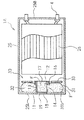
発明の実施の形態を実施例により説明する。図1、図2、および図3は本発明の第1の実施例の構成を示す図である。図1は全体の構成図である。図2は外観図である。図3はガス放出機構部の一部破断斜視図である。
電池1は、4角形状のケース2内に電極3を備える。ケースの上壁2aには電極端子4が設けられ、電極3と接続されている。
そして、ケース2内の電極の下側スペースRにはガス放出機構10が設けられている。
【0007】
ガス放出機構10は、ケースの下壁2bの中心に形成された穴にガス流通路12を一致させて取り付けられた円筒状のノズル11を備えている。ノズル11は一端(出口端)が下壁2bに固定され、他端(入口端)がケース2内を電極3方向へ延びている。
ノズル11のガス流路部12の断面積は、下壁2bの面積の10分の1以下に設定されている。ノズル11の入口端および出口端には各々第1の開裂弁17、第2の開裂弁18が設けられ、ガス流路部12を遮断している。なお、開裂弁18の外側には、開裂弁18の外部からの損傷を防止するため、防護ブリッジ19aを有する弁カバー19が取り付けられている。
開裂弁17および18は発明の第1の圧力弁および第2の圧力弁を構成する。
【0008】
ノズル11の入口端側からケース2の側壁付近まで放射状に延び、周縁部が下壁2bに固定される袋状の柔軟膜隔壁20が設けられている。柔軟膜隔壁20の上記ノズル入口端側への固定は、入口端の外周に形成された段部15とこの段部にはめられる固定リング16との間に挟まれて固定され、また、周縁部20bの下壁2bへの固定は接着によりなされている。
これにより、柔軟膜隔壁20、下壁2bならびにノズル11の側壁13とで画成される消化剤収納室21が、スペースS内に形成される。
【0009】
ノズル11の側壁13には周方向に多数の孔14が形成され、ガス流路部12と消化剤収納室21とが連通するようになっている。消化剤収納室21には粉末状の消火剤Fが満たされるとともに、第1、第2の開裂弁17、18で閉ざされたノズルのガス流路部12にも消火剤Fが充填されている。
【0010】
次に、電極間の短絡等によって発熱し、急激な反応がおこってガスが発生した場合の、ガス放出機構10の作用について説明する。
ケース2内のガス圧が上昇すると、そのガス圧によって開裂弁17および18が開き、まずガス流路部12に満たされていた消火剤Fがガス噴出と同時に一度に放出される。
【0011】
ここで、図5に、開裂弁17および18が開き、ガス流路部12に満たされていた消火剤Fが放出された後の、ケース2内およびガス流路部12でのガス圧とガス速度の関係を示す。
ケース2のAーA断面での断面積をS1、ガス圧をP1、ガス速度をV1とし、ガス流路部12のBーB断面での断面積をS2、ガス圧をP2,ガス速度をV2とする。
ガス密度をρとすると、流体力学における連続の式より、流体密度と流速と断面積の積は一定であるので、
ρ・V1・S1=ρ・V2・S2 (1)
と表せる。
【0012】
ガス流をガス密度ρが一定である流体と考えると、V2は、
V2=(S1/S2)・V1 (2)
となる。
流体中の圧力と、流速および流体密度の関係を示すベルヌーイの定理から、ガス密度ρ、ガス速度V1、V2およびガス圧P1,P2の関係は
(1/2)ρV12 +P1=(1/2)ρV22 +P2 (3)
と表せる。
【0013】
ここで、ノズル11の孔14における圧力差ΔPを考える。消火剤収納室21内にはケース内AーA断面と同じ圧力P1が加えられているので、
ΔP=P2−P1 (4)
と表せる。式(4)および式(3)から、
V22 >>V12 (6)
とみなせる。式(5)および式(6)から、
ΔP=P2−P1=(1/2)ρV22 (7)
と表せる。
したがって、ノズル11の孔14における圧力差ΔPにより、消火剤収納室21内の消火剤Fが孔14から吸い出され、噴出するガスと消火剤Fが混合されて、放出される。
【0014】
本実施例は以上のように構成され、まず、ノズル11のガス流路部12に満たされていた消火剤Fが最初のガス噴出と同時に放出されるので、ケース2外部のノズル11の周囲での発火が防止される。その後ノズル11の孔14から吸い出された消火剤収納室21の消火剤Fがガスに混合されて放出され、ガス放出により引き起こされる電池周囲での発火が持続的に防止される。したがって、消火剤が効率良く利用され、高い発火防止効果が得られる。
【0015】
図5および図6は本発明の第2の実施例の構成を示す図である。図5は全体の構成図である。図6は分解斜視図である。
電池1Aは、円筒状のケース25内に電極26を備える。ケースの右壁25aには電極端子4が設けられ、電極26と接続されている。ケースの左壁25b側には、ノズル11と消火剤Fを収納する消火剤収納室32を有するガス放出機構30が設けられている。
前実施例と同様に、左壁25bに固定されたノズル11の入口端および出口端には第1、第2の開裂弁17、18が設けられ、またノズル11の側壁13には孔14が形成されている。そして、柔軟膜隔壁31、左壁25bならびにノズル11の側壁13とで画成される消化剤収納室32が形成され、消化剤収納室32およびガス流路部12に消火剤Fが充填されている。
【0016】
本実施例ではさらに、柔軟膜隔壁31の電極26に面する側に当接するように、ドーナツ状の隔壁おさえ板33が配置されている。とくに図示しないが、隔壁おさえ板33がその当接位置から脱落しないよう、隔壁おさえ板33を保持する爪をケース25の壁またはノズル11に設けることができ、あるいは、隔壁おさえ板33を柔軟膜隔壁31に接着することもできる。
その他の構成は第1の実施例と同様である。
【0017】
この実施例においては、ケース25内のガス圧が上昇すると、前実施例と同様に、開裂弁17および18が開き、まずガス流路部12に満たされていた消火剤Fがガス噴出と同時に一度に放出される。その後、消火剤Fとガスが混合されて放出されるとき、本実施例では、柔軟膜隔壁31の電極側に配置された隔壁おさえ板33により、ケース25内のガス圧が均一かつ有効に柔軟膜隔壁31に加わるので、消火剤Fはより速やかにガスと混合される。
【0018】
これにより、第1の実施例と同様の効果が得られるとともに、さらに隔壁おさえ板33を介して柔軟膜隔壁31に均一圧力が加わるので、ガスと消火剤Fの混合が効率よく行われ、発火防止効果がより向上する。同じく隔壁おさえ板33により、電極に対してノズルや柔軟膜隔壁が下方に位置し電極端子が上壁に設けられる縦置き型のみでなく、図5に示されるように、電極端子4を横向きとし電極とノズルや柔軟膜隔壁が横方向に並ぶ横置きで用いられる電池においても確実に安定して消火剤が供給されるという効果を有する。
【0019】
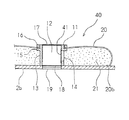
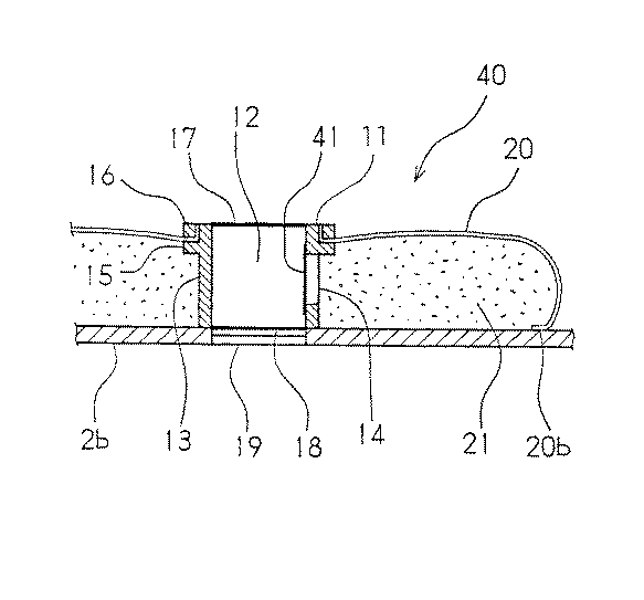
図7は本発明の第3の実施例を示すガス放出機構部の拡大図である。ガス放出機構40はノズル11と消火剤Fを収納する消火剤収納室21とを有する。
第1の実施例と同様に、下壁2bに固定されたノズル11の入口端および出口端には第1、第2の開裂弁17、18が設けられ、またノズルの側壁13には孔14が形成されている。そして、柔軟膜隔壁20、下壁2bならびにノズル11の側壁13とで画成される消化剤収納室21が形成され、消化剤収納室21に消火剤Fが充填されている。
ここで本実施例では、ノズル11の側壁13に形成された孔14が120℃で溶融する樹脂膜41で覆われ、ガス流路部12には、消火剤が封入されていない。
その他の構成は第1の実施例と同じである。
【0020】
この実施例では、ケース2内のガス圧が上昇すると、開裂弁17および18が開き、ガスが放出される。ガスの発生量が少ない時は、ガス温度の低いガスが放出されることが多く、樹脂膜41は溶融しないので、消火剤Fは放出されない。また、ガスの発生量が多く、ガス温度が120℃より高いガスが放出された時には、樹脂膜41が溶融して、第1の実施例と同様の作用により消火剤Fが消化剤収納室21から吸い出され、ガスに混合されて放出される。
【0021】
これにより、ガス温度が高い場合には、ノズル11の孔14から吸い出された消火剤Fがガスに混合されて放出され、ガス放出により引き起こされる電池周囲での発火が持続的に防止される。また、ガス温度が低く、発火を防止する必要が無い場合には、ガスのみが放出され、無駄に消火剤が放出されることがない。
【0022】
なお、柔軟膜隔壁を高温で溶融する材料を用いて作り、かつ電極と接する様に配置すれば、電極が高温状態になったときには、柔軟膜隔壁の当該高温箇所の電極に接する部位が溶融して穴が形成される。これにより、消化剤収納室の消火剤が効果的に電極の高温箇所へ供給される。
【0023】
【発明の効果】
以上のとおり、本発明は、第1および第2の圧力弁を配してケース内の圧力が所定値になるとガスを放出するノズルを設けるとともに、ノズルの側壁と協同して、消火剤収納室を形成する柔軟膜隔壁を設け、ノズルの側壁に消火剤収納室とガス流通路を連通する孔を形成したので、ガスが放出される際、ノズルの孔から消火剤が吸い出される。これにより、重量を増加することなく、持続的にガスと消火剤が放出され、消火剤が効率よく利用されて高い発火防止効果が得られる。
【図面の簡単な説明】
【図1】本発明の第1の実施例を示す図である。
【図2】第1の実施例の外観図である。
【図3】ガス放出機構部の一部破断斜視図である。
【図4】ガス圧とガス速度の関係を示す図である。
【図5】第2の実施例を示す図である。
【図6】第2の実施例の分解斜視図である。
【図7】第3の実施例を示すガス放出機構部の部分拡大図である。
【図8】従来例を示す図である。
【符号の説明】
1、1A 電池
2 ケース
2b 下壁
3、26 電極
4 電極端子
10、30、40 ガス放出機構
11 ノズル
12 ガス流路部
13 側壁
14 孔
15
16 固定リング
17、18 開裂弁
19 弁カバー
20、31 柔軟膜隔壁
21、32 消火剤収納室
25 ケース
25b 左壁
33 隔壁おさえ板
41 樹脂膜
R スペース
F 消化剤[0001]
BACKGROUND OF THE INVENTION
The present invention relates to a battery gas release mechanism.
[0002]
[Prior art]
Conventionally, in order to prevent the occurrence of a fire in the event of a battery abnormality, for example, there has been a configuration in which a fire extinguishing cylinder pressurized is disposed around the battery and a fire extinguishing agent is ejected when the temperature rises. However, such a configuration is less effective in terms of a large increase in weight and prevention of ignition.
As a countermeasure against this, Japanese Patent Laid-Open No. 50-4536 discloses a gas discharge mechanism for a battery as shown in FIG. Here, a
[0003]
[Problems to be solved by the invention]
However, in such a conventional battery gas release mechanism, as shown in FIG. 8B, once a part of the fire extinguishing agent is released and the
Therefore, in view of the above-described conventional problems, an object of the present invention is to provide a gas discharge mechanism for a battery that can efficiently use a fire extinguishing agent and obtain a high ignition prevention effect without increasing the weight.
[0004]
[Means for Solving the Problems]
In order to achieve the above object, the present invention provides a gas discharge mechanism of a battery including an electrode in a case, the nozzle fixed to one wall of the case, and extending into the case to form a gas flow path. A flexible membrane partition that extends from the inlet end side of the nozzle and cooperates with at least the side wall of the nozzle to form a fire extinguishing agent storage chamber in the space between the one wall and the electrode, and the inlet end and the outlet end of the nozzle. A first pressure valve and a second pressure valve that are opened when the pressure in the case reaches a predetermined value, and a side wall of the nozzle is provided with a hole communicating with the fire extinguishing agent storage chamber and the gas flow passage, The chamber was filled with digestive agent.
A partition presser plate can be placed in contact with the electrode side of the flexible membrane partition.
The digesting agent can also be filled into the gas flow passage of the nozzle, or the hole on the side wall of the nozzle can be covered with a resin film that melts at high temperature.
[0005]
[Action]
When the gas pressure in the case rises, the first and second pressure valves at both ends of the nozzle are opened to release gas. At this time, the cross-sectional area of the gas flow path is smaller than the cross-sectional area of the case, and the gas flow speed in the gas flow path of the nozzle is larger than the gas flow speed in the case. Therefore, the gas pressure in the gas flow passage is smaller than that in the case and the extinguishing agent storage chamber, and a pressure difference is generated in the hole portion of the nozzle. Due to this pressure difference, the extinguishing agent is sucked out of the nozzle hole, mixed with the gas, and the gas and the extinguishing agent are continuously released.
[0006]
DETAILED DESCRIPTION OF THE INVENTION
Embodiments of the invention will be described with reference to examples. 1, 2 and 3 are diagrams showing the configuration of the first embodiment of the present invention. FIG. 1 is an overall configuration diagram. FIG. 2 is an external view. FIG. 3 is a partially broken perspective view of the gas release mechanism.
The
A
[0007]
The
The cross-sectional area of the gas
The
[0008]
A bag-like flexible
As a result, a digestive
[0009]
A large number of
[0010]
Next, the operation of the
When the gas pressure in the
[0011]
Here, in FIG. 5, the gas pressure and gas in the
The cross-sectional area of the
If the gas density is ρ, the product of fluid density, flow velocity, and cross-sectional area is constant from the continuity equation in fluid dynamics.
ρ · V1 · S1 = ρ · V2 · S2 (1)
It can be expressed.
[0012]
Considering the gas flow as a fluid with a constant gas density ρ, V2 is
V2 = (S1 / S2) · V1 (2)
It becomes.
From Bernoulli's theorem showing the relationship between the pressure in the fluid, the flow velocity and the fluid density, the relationship between the gas density ρ, the gas velocities V1, V2, and the gas pressures P1, P2 is (1/2) ρV1 2 + P1 = (1/2 ) ΡV2 2 + P2 (3)
It can be expressed.
[0013]
Here, the pressure difference ΔP in the
ΔP = P2−P1 (4)
It can be expressed. From Equation (4) and Equation (3),
V2 2 >> V1 2 (6)
Can be considered. From Equation (5) and Equation (6),
ΔP = P2−P1 = (1/2) ρV2 2 (7)
It can be expressed.
Therefore, the extinguishing agent F in the extinguishing
[0014]
The present embodiment is configured as described above. First, since the fire extinguishing agent F filled in the gas
[0015]
5 and 6 are diagrams showing the configuration of the second embodiment of the present invention. FIG. 5 is an overall configuration diagram. FIG. 6 is an exploded perspective view.
The
As in the previous embodiment, first and
[0016]
In this embodiment, a donut-shaped
Other configurations are the same as those of the first embodiment.
[0017]
In this embodiment, when the gas pressure in the
[0018]
As a result, the same effect as in the first embodiment can be obtained, and a uniform pressure is further applied to the
[0019]
FIG. 7 is an enlarged view of a gas release mechanism portion showing a third embodiment of the present invention. The
As in the first embodiment, first and
Here, in this embodiment, the
Other configurations are the same as those of the first embodiment.
[0020]
In this embodiment, when the gas pressure in the
[0021]
Thereby, when the gas temperature is high, the fire extinguishing agent F sucked out from the
[0022]
If the flexible membrane partition is made of a material that melts at a high temperature and is placed in contact with the electrode, when the electrode reaches a high temperature, the portion of the flexible membrane partition that contacts the electrode at the high temperature melts. Hole is formed. Thereby, the fire extinguisher of a digestive agent storage chamber is effectively supplied to the high temperature location of an electrode.
[0023]
【The invention's effect】
As described above, according to the present invention, the first and second pressure valves are arranged to provide the nozzle for releasing the gas when the pressure in the case reaches a predetermined value, and in cooperation with the side wall of the nozzle, the fire extinguisher storage chamber And a hole for communicating the extinguishing agent storage chamber and the gas flow passage is formed in the side wall of the nozzle, so that when the gas is released, the extinguishing agent is sucked out from the hole of the nozzle. Thereby, without increasing the weight, the gas and the extinguishing agent are continuously released, and the extinguishing agent is efficiently used to obtain a high ignition prevention effect.
[Brief description of the drawings]
FIG. 1 is a diagram showing a first embodiment of the present invention.
FIG. 2 is an external view of a first embodiment.
FIG. 3 is a partially broken perspective view of a gas discharge mechanism.
FIG. 4 is a diagram showing the relationship between gas pressure and gas velocity.
FIG. 5 is a diagram showing a second embodiment.
FIG. 6 is an exploded perspective view of a second embodiment.
FIG. 7 is a partially enlarged view of a gas discharge mechanism showing a third embodiment.
FIG. 8 is a diagram showing a conventional example.
[Explanation of symbols]
DESCRIPTION OF
16 Fixing rings 17 and 18
Claims (4)
前記ケースの一つの壁に固定され、ケース内に延びてガス流通路を形成するノズルと、
該ノズルの入口端側から延びるとともに、少なくともノズルの側壁と協同して、前記一つの壁と電極の間のスペースに消火剤収納室を形成する柔軟膜隔壁と、
前記ノズルの入口端および出口端に設けられ、前記ケース内の圧力が所定値になると開く第1および第2の圧力弁とを有し、
前記ノズルの側壁には前記消火剤収納室とガス流通路を連通する孔が設けられ、前記消火剤収納室に消化剤が充填されていることを特徴とする電池のガス放出機構。A gas release mechanism of a battery including an electrode in a case,
A nozzle fixed to one wall of the case and extending into the case to form a gas flow path;
A flexible membrane partition which extends from the inlet end side of the nozzle and forms a fire extinguishing agent storage chamber in a space between the one wall and the electrode in cooperation with at least the side wall of the nozzle;
First and second pressure valves provided at an inlet end and an outlet end of the nozzle and opened when a pressure in the case reaches a predetermined value;
A gas discharge mechanism for a battery, wherein a hole communicating with the extinguishing agent storage chamber and a gas flow path is provided in a side wall of the nozzle, and the extinguishing agent storage chamber is filled with a digestive agent.
Priority Applications (1)
| Application Number | Priority Date | Filing Date | Title |
|---|---|---|---|
| JP34457595A JP3658825B2 (en) | 1995-12-05 | 1995-12-05 | Battery gas release mechanism |
Applications Claiming Priority (1)
| Application Number | Priority Date | Filing Date | Title |
|---|---|---|---|
| JP34457595A JP3658825B2 (en) | 1995-12-05 | 1995-12-05 | Battery gas release mechanism |
Publications (2)
| Publication Number | Publication Date |
|---|---|
| JPH09161754A JPH09161754A (en) | 1997-06-20 |
| JP3658825B2 true JP3658825B2 (en) | 2005-06-08 |
Family
ID=18370339
Family Applications (1)
| Application Number | Title | Priority Date | Filing Date |
|---|---|---|---|
| JP34457595A Expired - Lifetime JP3658825B2 (en) | 1995-12-05 | 1995-12-05 | Battery gas release mechanism |
Country Status (1)
| Country | Link |
|---|---|
| JP (1) | JP3658825B2 (en) |
Cited By (1)
| Publication number | Priority date | Publication date | Assignee | Title |
|---|---|---|---|---|
| KR20160131396A (en) * | 2015-05-07 | 2016-11-16 | 주식회사 엘지화학 | Pouch-Typed Battery Cell of Double Case Structure |
Families Citing this family (10)
| Publication number | Priority date | Publication date | Assignee | Title |
|---|---|---|---|---|
| JP2009211909A (en) | 2008-03-04 | 2009-09-17 | Panasonic Corp | Battery, battery pack, and method of manufacturing connection terminals used therefor |
| JP5181743B2 (en) * | 2008-03-11 | 2013-04-10 | パナソニック株式会社 | Power supply equipment and electronic equipment using it |
| JP2012221717A (en) * | 2011-04-08 | 2012-11-12 | Panasonic Corp | Battery module |
| KR102311426B1 (en) * | 2014-08-11 | 2021-10-12 | 삼성에스디아이 주식회사 | Secondary Battery and Battery Module Including Secondary Battery |
| CN109585723A (en) * | 2017-09-29 | 2019-04-05 | 郑州宇通客车股份有限公司 | Battery case, safety battery, battery modules, battery case and vehicle |
| DE102018112284A1 (en) | 2018-05-23 | 2019-11-28 | Volkswagen Aktiengesellschaft | Battery with extinguishing device and motor vehicle |
| JP7379812B2 (en) * | 2018-10-01 | 2023-11-15 | 大日本印刷株式会社 | Valve structure, container including the same, and electricity storage device with valve structure |
| CN115398722A (en) | 2020-04-17 | 2022-11-25 | 松下知识产权经营株式会社 | Cylindrical battery |
| CN116325274A (en) * | 2020-10-14 | 2023-06-23 | 三洋电机株式会社 | Sealed battery |
| CN112952252A (en) * | 2021-01-28 | 2021-06-11 | 江苏塔菲尔动力系统有限公司 | Structure for preventing battery explosion, battery module and battery pack |
-
1995
- 1995-12-05 JP JP34457595A patent/JP3658825B2/en not_active Expired - Lifetime
Cited By (2)
| Publication number | Priority date | Publication date | Assignee | Title |
|---|---|---|---|---|
| KR20160131396A (en) * | 2015-05-07 | 2016-11-16 | 주식회사 엘지화학 | Pouch-Typed Battery Cell of Double Case Structure |
| KR102019391B1 (en) * | 2015-05-07 | 2019-09-06 | 주식회사 엘지화학 | Pouch-Typed Battery Cell of Double Case Structure |
Also Published As
| Publication number | Publication date |
|---|---|
| JPH09161754A (en) | 1997-06-20 |
Similar Documents
| Publication | Publication Date | Title |
|---|---|---|
| JP3658825B2 (en) | Battery gas release mechanism | |
| US11462801B2 (en) | Battery module having structure capable of preventing inflow of air into module when thermal runaway occurs and battery pack including same | |
| US20050194312A1 (en) | Additive dispensing fluid filter | |
| KR100386001B1 (en) | Device to exhaust smoke generated in battery | |
| JPH01150100A (en) | Method of preventing storage of pressure of gas body | |
| KR102566979B1 (en) | secondary battery and battery pack including the same | |
| BRPI0719903B1 (en) | liquid propulsion device incorporating a pyrotechnic gas generator in its structure | |
| US4194569A (en) | Fire extinguishers | |
| KR102512593B1 (en) | Battery module | |
| CN111617410A (en) | Fire extinguishing device | |
| JP4097701B2 (en) | Explosion suppressor spray nozzle | |
| US20070057496A1 (en) | Gas generator for air bag | |
| CN213220685U (en) | Fire extinguishing device | |
| US5018585A (en) | Safety device to relieve explosive pressures | |
| JP3037506B2 (en) | Fire extinguishing method and apparatus for sodium-sulfur battery | |
| CN218280354U (en) | Energy storage container inter-cluster separation type fire-fighting system | |
| JP2703430B2 (en) | Fire extinguisher in sodium-sulfur battery | |
| EP0979125B1 (en) | Explosion suppression arrangements and methods | |
| JP3878465B2 (en) | Automatic fire extinguisher | |
| CN216055056U (en) | Battery module apron, battery module and new energy automobile | |
| US1597526A (en) | Cartridge for fire extinguishers and the like | |
| CN112787029B (en) | Battery system for vehicle and vehicle | |
| EP0204503B1 (en) | High pressure gas cartridge | |
| CN116799429A (en) | Battery assembly, active fire extinguishing battery system, design method and vehicle | |
| CN217366984U (en) | Fire extinguishing device |
Legal Events
| Date | Code | Title | Description |
|---|---|---|---|
| A977 | Report on retrieval |
Free format text: JAPANESE INTERMEDIATE CODE: A971007 Effective date: 20040827 |
|
| TRDD | Decision of grant or rejection written | ||
| A01 | Written decision to grant a patent or to grant a registration (utility model) |
Free format text: JAPANESE INTERMEDIATE CODE: A01 Effective date: 20050222 |
|
| A61 | First payment of annual fees (during grant procedure) |
Free format text: JAPANESE INTERMEDIATE CODE: A61 Effective date: 20050307 |
|
| R150 | Certificate of patent or registration of utility model |
Free format text: JAPANESE INTERMEDIATE CODE: R150 |
|
| FPAY | Renewal fee payment (event date is renewal date of database) |
Free format text: PAYMENT UNTIL: 20090325 Year of fee payment: 4 |
|
| FPAY | Renewal fee payment (event date is renewal date of database) |
Free format text: PAYMENT UNTIL: 20090325 Year of fee payment: 4 |
|
| FPAY | Renewal fee payment (event date is renewal date of database) |
Free format text: PAYMENT UNTIL: 20100325 Year of fee payment: 5 |
|
| FPAY | Renewal fee payment (event date is renewal date of database) |
Free format text: PAYMENT UNTIL: 20100325 Year of fee payment: 5 |
|
| FPAY | Renewal fee payment (event date is renewal date of database) |
Free format text: PAYMENT UNTIL: 20110325 Year of fee payment: 6 |
|
| FPAY | Renewal fee payment (event date is renewal date of database) |
Free format text: PAYMENT UNTIL: 20110325 Year of fee payment: 6 |
|
| FPAY | Renewal fee payment (event date is renewal date of database) |
Free format text: PAYMENT UNTIL: 20120325 Year of fee payment: 7 |
|
| FPAY | Renewal fee payment (event date is renewal date of database) |
Free format text: PAYMENT UNTIL: 20130325 Year of fee payment: 8 |