JP3653426B2 - refrigerator - Google Patents

refrigerator Download PDF

Info

Publication number
JP3653426B2
JP3653426B2 JP30083499A JP30083499A JP3653426B2 JP 3653426 B2 JP3653426 B2 JP 3653426B2 JP 30083499 A JP30083499 A JP 30083499A JP 30083499 A JP30083499 A JP 30083499A JP 3653426 B2 JP3653426 B2 JP 3653426B2
Authority
JP
Japan
Prior art keywords
refrigerator
heat exchange
refrigerant
compressor
chamber
Prior art date
Legal status (The legal status is an assumption and is not a legal conclusion. Google has not performed a legal analysis and makes no representation as to the accuracy of the status listed.)
Expired - Fee Related
Application number
JP30083499A
Other languages
Japanese (ja)
Other versions
JP2001116428A (en
Inventor
秀雄 白石
Current Assignee (The listed assignees may be inaccurate. Google has not performed a legal analysis and makes no representation or warranty as to the accuracy of the list.)
Sanyo Electric Co Ltd
Original Assignee
Sanyo Electric Co Ltd
Priority date (The priority date is an assumption and is not a legal conclusion. Google has not performed a legal analysis and makes no representation as to the accuracy of the date listed.)
Filing date
Publication date
Application filed by Sanyo Electric Co Ltd filed Critical Sanyo Electric Co Ltd
Priority to JP30083499A priority Critical patent/JP3653426B2/en
Publication of JP2001116428A publication Critical patent/JP2001116428A/en
Application granted granted Critical
Publication of JP3653426B2 publication Critical patent/JP3653426B2/en
Anticipated expiration legal-status Critical
Expired - Fee Related legal-status Critical Current

Links

Images

Description

【0001】
【発明の属する技術分野】
本発明は、冷媒配管の表面に熱交換用フィンを螺旋状に巻設した熱交換器を取り付けて成る冷蔵庫に関するものである。
【0002】
【従来の技術】
従来よりこの種家庭用冷蔵庫は、例えば特開平8−338681号公報(F25D23/00)に示される如く、鋼板製の外箱と硬質樹脂製の内箱間に発泡ポリウレタンなどの発泡断熱材を現場発泡方式にて充填した断熱箱体から構成されており、この断熱箱体内(庫内)を複数に区画することにより、冷凍室や冷蔵室、野菜室などを構成している。そして、冷凍室の後方には冷却器を設置して、この冷却器により冷却された冷気を各室に循環することにより、それぞれ所定の温度に冷却している。
【0003】
また、断熱箱体の下部には機械室が構成され、この機械室内には前記冷却器と共に冷凍サイクルを構成する圧縮機や凝縮器(熱交換器)、及び、これらを空冷するための送風機などが設置されている。そして、圧縮機が運転されている間、前記送風機も運転され、圧縮機及び凝縮器に通風して空冷する構成とされていた。
【0004】
また、前記凝縮器としては、例えば二列に構成された連続する冷媒配管の表面に、熱交換用フィンを螺旋状に巻設した熱交換器を採用したものもあり、係る凝縮器を機械室内に取り付ける際には、従来では例えばクリップなどを前記熱交換用フィン間から冷媒配管表面に係合させ、このクリップを機械室の底面にネジ止めするなどの方法が採られていた。
【0005】
【発明が解決しようとする課題】
しかしながら、熱交換用フィンは冷媒配管に螺旋状に巻回されているため、クリップを冷媒配管に係合させることは困難な作業となる。そこで、熱交換用フィンにネジ止め孔を形成して固定しようとすると、今度はネジ止めを行う部分に無理な力が加わり、熱交換用フィンが変形してしまうなどの問題が生じる。
【0006】
そして、このような理由から凝縮器を完全に固定することができない場合、冷蔵庫の運搬時などの振動により他の機器と接触し、その衝撃によって熱交換用フィンが変形したり、また、圧縮機の運転や送風機の運転により、凝縮器が振動し、騒音を発生させる問題が生じる。更には、凝縮器が傾いた状態で振動が発生すると、凝縮器の冷媒配管の接合部分に無理な応力が加わり、係る接合部分に損傷を来す問題もあった。
【0007】
本発明は、係る従来の技術的課題を解決するために成されたものであり、冷媒配管表面に熱交換用フィンを巻設して成る熱交換器を取り付けるに当たり、当該熱交換器を容易且つ確実に固定することができる冷蔵庫を提供するものである。
【0008】
【課題を解決するための手段】
本発明の冷蔵庫は、少なくとも左右二列で屈曲された連続する冷媒配管の表面に、熱交換用フィンを螺旋状に巻設した熱交換器を取り付けて成る冷蔵庫において、前記各列の冷媒配管及び熱交換用フィンをそれぞれ収容し、当該熱交換用フィンを挟持する複数の収容部を備えた第1の取付具と、二列の冷媒配管の熱交換用フィンに当接する本体及びこの本体から前記二列の冷媒配管の熱交換用フィン間に進入し、最下段の冷媒配管の中心から下から2段目の冷媒配管の中心間以上に渡る高さ寸法の突壁とを備えた第2の取付具とを備えたことを特徴とする。
【0009】
本発明によれば、少なくとも二列に構成された連続する冷媒配管の表面に、熱交換用フィンを螺旋状に巻設した熱交換器を取り付けて成る冷蔵庫において、各列の冷媒配管及び熱交換用フィンをそれぞれ収容し、当該熱交換用フィンを挟持する複数の収容部を備えた第1の取付具と、各列の冷媒配管の熱交換用フィンに当接する本体及びこの本体から各列の冷媒配管の熱交換用フィン間に進入する突壁とを備えた第2の取付具とを備えているので、各列の冷媒配管及び熱交換用フィンをそれぞれ第1の取付具の収容部内に収容することにより、熱交換器の外れは防止される。また、第2の取付具の突壁を各列の冷媒配管の熱交換用フィン間に進入させ、本体にて冷媒配管及び熱交換用フィンを支持することにより、熱交換器の傾きや水平方向への移動も防止することができる。これにより、熱交換器を容易且つ確実に取り付けることができると共に、熱交換用フィンの変形や破損も防止若しくは抑制することが可能となるものである。突壁は少なくとも二段の冷媒配管の中心間に渡る範囲よりも広い範囲で熱交換用フィン間に進入する寸法を備えるようにしたので、突壁により熱交換器を広い範囲で保持して、その傾きをより一層確実に防止することができるようになる。
【0010】
請求項2の発明の冷蔵庫は、上記に加えて収容部の開口寸法を熱交換用フィンの外径寸法よりも小さくしたことを特徴とする。
【0011】
請求項2の発明によれば、上記に加えて収容部の開口寸法を熱交換用フィンの外径寸法よりも小さくしたので、冷媒配管及び熱交換用フィンを収容部内に収容した状態で、熱交換用フィンは強固に挟持されるようになる。これにより、熱交換器がが第1の取付具の収容部から脱落することを一層確実に防止することができるようになるものである。
【0012】
【0013】
【0014】
【発明の実施の形態】
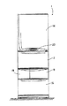
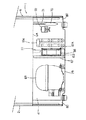
次に、図面に基づき本発明の実施形態を詳述する。図1は本発明を適用した冷蔵庫1の正面図、図2は冷蔵庫1の縦断側面図、図3は冷蔵庫1の冷蔵室11の背面板49及び背面断熱材50の分解斜視図、図4は冷蔵庫1の冷蔵室11部分の平断面図、図5は冷蔵庫1の仕切壁7部分の平断面図、図6は冷蔵庫1の冷凍サイクルの冷媒回路図である。
【0015】
冷蔵庫1は鋼板製の外箱2と、ABSなどの硬質樹脂製の内箱3間に発泡ポリウレタン等の断熱材4を現場発泡方式にて充填して成る前面開口の断熱箱体6から構成されている。この断熱箱体6の庫内は、断熱箱体6と一体に構成された断熱壁から成る仕切壁7により上下に区画されており、更に仕切壁7の上方の断熱箱体6内は上仕切部材8にて上下に区画されている。
【0016】
そして、この上仕切部材8の上方を冷蔵室11、上仕切部材8と仕切壁7間を野菜室12としている。更に、仕切壁7の下方の断熱箱体6の開口縁は下仕切部材9にて上下に区画され、この下仕切部材9の下側が冷凍室13とされている。また、仕切壁7と下仕切部材9の間は、断熱壁30(図5)にて更に左右に区画され、向かって左側を製氷室10、右側をセレクト室15(図5)としている。尚、図5では説明のため仕切壁7のハッチングを省略している。
【0017】
上記冷蔵室11の前面開口は回動自在の断熱扉14によって開閉自在に閉塞されると共に、冷凍室13及び野菜室12は、上面開口の容器16A、17Aを備えた引き出し式の断熱扉16、17によりそれぞれ開閉自在に閉塞されている。また、製氷室10も、上面開口の容器18Aを備えた引き出し式の断熱扉18により開閉自在に閉塞され、前記セレクト室15も同様の引き出し式の断熱扉19(図1)により開閉自在に閉塞されている。尚、20は扉14の前面下部に設けられたコントロールパネルである。
【0018】
また、製氷室10の上部には自動製氷機21が設置されている。更に、野菜室12の奥方は仕切板22及び冷却器前板23にて前後に区画され、冷却器前板23の後側に冷却室24が区画形成されており、この冷却室24内に冷蔵室用冷却器26が縦設されている。この冷蔵室用冷却器26の上側には冷蔵室用送風機27が設けられており、冷蔵室用冷却器26の下側には除霜ヒータ28が設けられている。また、この除霜ヒータ28の下側にはドレン受け29が形成されている。
【0019】
また、製氷室10及びセレクト室15の奥方から冷凍室13の上部奥方は仕切板32及び冷却器前板33にて前後に区画され、冷却器前板33の後側に冷却室34が区画形成されており、この冷却室34内に冷凍室用冷却器36が縦設されている。この冷凍室用冷却器36の上側には冷凍室用送風機37が設けられており、冷凍室用冷却器36の下側には除霜ヒータ38が設けられている。また、この除霜ヒータ38の下側にはドレン受け39が形成されている。
【0020】
そして、仕切板32の上部には製氷室吐出口やセレクト室吐出口などが形成され、中央部には冷凍室吐出口13Aが形成されると共に、仕切板32の下部には冷凍室吸込口13Bが形成されている。尚、図示しないセレクト室吐出口はセレクト室15の温度に基づいて流路を開閉する図示しないモータダンパーが取り付けられている。
【0021】
一方、野菜室12奥方の仕切板22下部には野菜室吸込口12Aが形成されると共に、仕切板22と冷却器前板23間の空間上端は後述する冷蔵室背面ダクト47に連通している。更に、仕切板22の上部には上仕切部材8下側に冷気を吹き出すための野菜室吐出口12Bが形成されている。
【0022】
他方、冷蔵室11の奥部には内箱3背面と間隔を存して背面板49とその裏側に背面断熱材50が取り付けられており、この背面断熱材50の裏面左右には、上下に延在する前記冷蔵室背面ダクト47が形成されている。そして、背面板49の左右には冷蔵室吐出口11Aが形成され、背面断熱材50を貫通して冷蔵室背面ダクト47に連通している。また、冷蔵室11内には棚51・・が複数段架設されている。
【0023】
また、背面板49の左右には背面断熱材50の両側に位置して上下に渡る凹所31、31が形成されており、各凹所31、31内にはそれぞれ照明灯59が取り付けられる。そして、この凹所31、31の前面は図示しない透光性のシェードにて閉塞される(尚、図2では左側の照明灯59を透視して見ている)。
【0024】
更に、冷蔵室11の下部には上仕切部材8の上方に所定の間隔を存して仕切板42が取り付けられており、この仕切板42の前側には開閉自在の蓋43が回動自在に吊下され、これらで囲繞される空間に内蔵室44が形成されている。そして、この内蔵室44内には引き出し自在の容器48が収納されている。尚、44Aは背面板49に形成された内蔵室吐出口であり、冷蔵室背面ダクト47下部に連通している。
【0025】
また、上仕切部材8には冷蔵室吸込口51が形成されており、この冷蔵室吸込口51は野菜室12内に連通している。更に、内蔵室44には前記自動製氷機21に給水するための図示しない給水タンクが収納される。
【0026】
前記野菜室12内に収納された容器17Aの上面は蓋53にて閉塞されており、前記冷蔵室11から帰還する冷気は、冷蔵室吸込口51を経てこの容器17A周囲に流通された後、野菜室吸込口12Aから冷却室24に戻される。また、前記製氷室10や冷凍室13からの帰還冷気は冷凍室吸込口13Bから冷却室34に戻される。尚、セレクト室15からは図示しないセレクト室吸込口から冷却室34に戻される。
【0027】
ここで、背面断熱材50の前面中央部には上下に渡って凹陥した凹陥部54が形成されており、この凹陥部54の下部に対応する位置の背面板49には吸込口56が取り付けられている。そして、背面板49にて閉塞された凹陥部54内にエアーカーテン用背面ダクト57が形成され、その中には温度補償用電気ヒータHが取り付けられている。尚、55は吸込口56に取り付けられたカバーである。
【0028】
吸込口56の後方に位置するエアーカーテン用背面ダクト57内には軸方向(前方)から冷気を吸引して半径方向に吹き出すターボファン67を備えたエアーカーテン用送風機68が配設されている。また、冷蔵室11の天面には天面板63が取り付けられ、この天面板63内にはエアーカーテン用天面ダクト64が前後に渡って構成されている。このエアーカーテン用天面ダクト64の後端は前記エアーカーテン用背面ダクト57の上端に連通しており、エアーカーテン用天面ダクト64の前端には、冷蔵室11の前面開口近傍に位置して複数の吹出口66・・が左右に並設されている(尚、図2では送風機68を透視して見ている)。
【0029】
一方、断熱箱体6の下部には機械室41が構成されており、この機械室41内後部には前記冷蔵室用冷却器26や冷凍室用冷却器36と共に図6の冷凍サイクルの冷媒回路を構成する圧縮機69などが設置されている。この図6の冷媒回路図において、71は凝縮装置であり、72はモータ駆動の三方弁、73及び74はキャピラリチューブである。尚、キャピラリチューブ73、74と後述する冷媒吸込配管69Sは熱交換可能にハンダ付けされている。
【0030】
そして、圧縮機69の冷媒吐出配管69Dは凝縮装置71に接続され、凝縮装置71の出口部71Aはドライヤ70を経て三方弁72に接続される。三方弁72の一方の出口はキャピラリチューブ73を経て冷蔵室用冷却器26の入口に接続され、冷蔵室用冷却器26の出口は冷凍室用冷却器36の入口に接続されている。
【0031】
また、三方弁72の他方の出口はキャピラリチューブ74を経て冷凍室用冷却器36の入口に接続されると共に、冷凍室用冷却器36の出口は圧縮機69の冷媒吸込配管69Sに接続されている。尚、三方弁72は凝縮装置71からの液冷媒をキャピラリチューブ73かキャピラリチューブ74に択一的に流すよう出口を開閉する機能を備えると共に、双方の出口を閉じて流路を完全に閉鎖する機能と双方の出口を開放する機能をも有する。また、40は冷凍室用冷却器36と圧縮機69間に接続された冷媒液溜としてのヘッダーである。
【0032】
そして、図示しない制御装置により圧縮機69が運転されると、圧縮機69の冷媒吐出配管69Dから吐出された高温高圧のガス冷媒は凝縮装置71に流入して放熱し、凝縮液化される。そして、凝縮装置71を出た冷媒はドライヤ70を経て三方弁72に入る。
【0033】
冷凍室13と冷蔵室11の温度を検出する図示しない温度センサの双方からの冷却要求がある場合、前記制御装置は三方弁72をキャピラリチューブ73側に開放する。これにより、凝縮装置71で凝縮液化された冷媒はキャピラリチューブ73で減圧された後、冷蔵室用冷却器26と冷凍室用冷却器36とに順次流入して蒸発し、双方の冷却器で冷却能力を発揮する。また、冷凍室13の温度センサみから冷却要求がある場合、前記制御装置は三方弁72をキャピラリチューブ74側に開放する。これにより、凝縮装置71で凝縮液化された冷媒はキャピラリチューブ74で減圧された後、冷凍室用冷却器36に流入して蒸発し、冷凍室用冷却器36で冷却能力を発揮する。そして、冷凍室13と冷蔵室11の双方の温度センサから冷却要求が無い場合、前記制御装置は圧縮機69を停止(送風機27、37も停止)すると共に、三方弁72の双方の出口を閉じ、流路を完全に閉鎖する。
【0034】
そして、冷凍室用送風機37が運転されると、冷凍室用冷却器36にて冷却された冷却室34内の冷気は製氷室吐出口やセレクト室吐出口から製氷室10やセレクト室15に吐出されると共に、冷凍室吐出口13Aから冷凍室13に吐出される。そして、各室内を循環して冷却した後、冷気は前記冷凍室吸込口13Bから冷却室34内に帰還する(図2中実線矢印)。これによって、冷凍室13は所定の冷凍温度(−20℃程)に維持される。
【0035】
尚、製氷室10内の温度も凍結温度となるように構成され、自動製氷機21によて製氷が成される。また、セレクト室15内は冷凍室から野菜室の範囲で制御温度が選択可能とされており、当該選択された温度となるように前記モータダンパーによりセレクト室吐出口からの冷気供給量が制御される。このモータダンパーはセレクト室15の温度を検出する図示しない温度センサに基づき、前記制御装置によって制御される。
【0036】
一方、冷蔵室用送風機27が運転されると、冷蔵室用冷却器26にて冷却された冷却室24内の冷気は冷蔵室背面ダクト47に流入し、冷蔵室吐出口11A・・・や内蔵室吐出口44Aから冷蔵室11、内蔵室44内に吹き出され、内部を循環して冷却した後、冷蔵室吸込口51に流入する。
【0037】
冷蔵室吸込口51に流入した冷気は上仕切部材8を通過し、野菜室吐出口12Bから吹き出された冷気と混ざり合って野菜室12内に入り、容器17A周囲を循環して容器17A内を間接的に冷却した後、野菜室吸込口12Aから吸い込まれ、冷却室24に帰還する。これによって、冷蔵室11内は冷蔵温度(+3℃〜+5℃程)に維持され、容器17A内の野菜は乾燥が防がれた状態で保冷されることになる(図2中実線矢印)。
【0038】
前記制御装置は前記温度センサが検出する冷凍室13の温度に基づいて冷凍室用送風機37をON−OFF制御し、冷蔵室11の温度に基づいて冷蔵室用送風機27をON−OFF制御しているが、扉14、17の何れかが開放された場合には、冷蔵室用送風機27を停止すると共に、扉16、18、19の何れかが開放された場合には、冷凍室用送風機37を停止する。これによって、各室からの冷気漏洩を抑制するものである。
【0039】
また、制御装置は冷蔵室11の扉14が閉じられており、且つ、冷蔵室11内の温度が例えば+6℃などの所定の高温度より低い場合には、エアーカーテン用送風機68を停止している。そして、扉14が開放されると、制御装置はこのエアーカーテン用送風機68を運転すると共に、照明灯59を点灯する。
【0040】
エアーカーテン用送風機68が運転されると、軸方向から冷気を吸引して半径方向に吹き出す作用を奏するので、冷蔵室11内の冷気はカバー55を介して吸引口56から吸引され、エアーカーテン用送風機68に吸い込まれる。そして、エアーカーテン用背面ダクト57に吹き出され、そこを上昇して、エアーカーテン用天面ダクト64に入り、そこを前方に流れて吹出口66から下方の冷蔵室11の開口部に吹き出される。
【0041】
これによって、冷蔵室11の開口部には全域に渡って図2に破線矢印で示す如く冷気エアーカーテンが形成されるので、扉14が開放された際に冷蔵室11内に侵入しようとする外気及び冷蔵室11内から漏洩しようとする冷気を、エアーカーテンによって極力阻止することができるようになる。
【0042】
ここで制御装置は、扉14が開放されている時間を積算しており、扉14が閉じられた場合には、前記積算時間と同じ時間だけエアーカーテン用送風機68の運転を継続して行った後、停止する。これにより、扉14の開放中に生じた冷蔵室11内の温度上昇や温度むらを、扉14を閉じた後に迅速に低下及び均一化させることができる。そして更に、例えば多量の熱負荷が投入されるなどして冷蔵室11内の温度が例えば+6℃などの高温度以上に上昇した場合には、制御装置は扉14が閉じられて更に前記積算時間が経過した後であってもエアーカーテン用送風機68を運転する。
【0043】
これにより、冷蔵室11内の冷気は撹拌されるので、冷蔵室11内の温度回復(低下)は迅速化される。また、上記の如きエアーカーテン用送風機68の運転によって冷蔵室11内の冷気が撹拌されることにより、冷蔵室11内の温度が均一化する作用も奏する。また、扉14が開放された場合に冷気エアーカーテンを形成するようにしているので、省エネルギーにも寄与できるようになる。更に、扉14が閉じられた状態でも、冷蔵室11内の温度が所定値以上に上昇した場合には、エアーカーテン用送風機68を運転するようにしたので、冷蔵室11内の冷気をエアーカーテン用送風機68の運転によって撹拌し、冷蔵室11内の温度回復(低下。特に扉14内側のポケットなど)を迅速化することができる。
【0044】
また、前記制御装置は圧縮機69の運転時間を積算しており、通算の運転時間が所定時間に達すると前記除霜ヒータ28及び38を発熱させる。これにより、冷蔵室用冷却器26及び冷凍室用冷却器36は加熱され、それらに付着した霜は融解される。着霜の融解により生じたドレン水は、各冷却器の下側に配置されたドレン受け29及び39にそれぞれ受容される。
【0045】
次に、図7〜図16を参照して冷蔵庫1の機械室41内の構成を詳細に説明する。このうち図7は冷蔵庫1下部の縦断側面図、図8は同冷蔵庫1下部の背面図、図9は冷蔵庫1の機械室41内の平面図、図10は機械室41部分の冷蔵庫1の分解斜視図、図11、図12は機械室41前部の冷蔵庫1の拡大縦断側面図、図13は冷蔵庫1下部の拡大正面図である。
【0046】
機械室41の天面となる断熱箱体6の底面6Aは、前部が低く後部のみが高い階段形状を呈しており、機械室41の前面、底面及び後面は開放している。この機械室41の底面後部には左右底面のアングル材80、80間に渡って圧縮機台79が取り付けられており、この圧縮機台79の前方から見て右側上に圧縮機69が設置されている。
【0047】
また、機械室41の前方にはキックプレート82が扉16の下側において左右に渡り断熱箱体6の前面に取り付けられており、このキックプレート82と前記圧縮機台79間には冷凍サイクルの凝縮装置71の一部を構成するプレートタイプの蒸発皿用コンデンサ83が機械室41の底部に位置してアングル材80、80に取り付けられ、底面6Aと設置床面との間に間隔を存して配置されている。
【0048】
そして、この蒸発皿用コンデンサ83上には蒸発皿90が載置され、蒸発皿用コンデンサ83と底面6A間に位置する。尚、図中95、95は蒸発皿用コンデンサ83の両側上に前後に渡って設けられ、この蒸発皿90を前後に摺動自在に保持するための蒸発皿レールである。
【0049】
この機械室41内は圧縮機69の前側に位置する仕切板84によって蒸発皿用コンデンサ83側と圧縮機台79側とに仕切られており、仕切板84の左側に連通部86が構成されている。また、圧縮機69の左側には例えば合成樹脂製のファン仕切板87が取り付けられており、このファン仕切板87には開口87Aが形成されている。このファン仕切板87には、前方に低く傾斜した収納部103が一体に成形されており、この収納部103の奥部は前記開口87Aにて左右に開口し、後面は開口103Aにて後方に向けて開放している。
【0050】
そして、この収納部103内には機械室用送風機88が後面の開口103Aから挿入され、取り付けられる。この機械室用送風機88は、全体形状が略正方形を呈した角形の軸流ファンであり、モータ部88Mが中央となり、ファン部88Fがその周囲に配置された構成である。また、機械室用送風機88は収納部103内奥部に挿入された状態で、開口87Aに位置すると共に、収納部103の傾斜により、図7に示す如く全体としては前下がりとなるよう傾斜している。
【0051】
これにより、機械室用送風機88の上面88Aはその軸方向から見て蒸発皿用コンデンサ83側に低く傾斜している。また、係る傾斜配置によってファン仕切板87の後下隅部には圧縮機台79との間に間隔が構成されるため、ここを利用して冷凍サイクルの冷媒配管75を挿通させることができる。
【0052】
また、ファン仕切板87の後部には鏃状の爪部87Bが一体に成形されており、機械室用送風機88が所定位置に収納された状態で、爪部87Bは機械室用送風機88の後面に突出する。これにより、機械室用送風機88は後方に抜けなくなる。尚、機械室用送風機88を収納部103から後方に引く抜く際には先ず後述するユニットカバー91を外し、爪部87Bを外側に変形させてから後方に引き出せば良い。
【0053】
この機械室用送風機88は運転されて連通部86側から空気を吸引し、圧縮機69側に吹き出す。また、機械室用送風機88の空気吸込側には前記凝縮装置71の一部を構成する主凝縮器104が圧縮機台79上に設置されている。図14はこの主凝縮器104と圧縮機台79の分解説明図、図15は第1の取付具としての取付具142と主凝縮器104の背面図、図16は第2の取付具としての取付具143と主凝縮器104の背面図である。
【0054】
主凝縮器104は各図に示す如く、左右二列、上下六段に屈曲された連続する冷媒配管141から成り、この冷媒配管141の表面に、アルミニウム薄板などの熱伝導金属性の板状熱交換用フィン140が螺旋状に巻設された構造とされている。
【0055】
そして、係る主凝縮器104は例えば硬質合成樹脂製の取付具142及び143によって圧縮機台79上に取り付けられる。ここで、取付具(第1の取付具)142には上方に開口する二つの収容部142A、142Aが形成されており、各収容部142Aの開口寸法は、前記主凝縮器104の熱交換用フィン140の外径寸法よりも少許小さく形成されていると共に、開口両縁には外側斜め上方に向けて突出したフランジ142Bがそれぞれ形成されている。
【0056】
また、取付具142の下部後縁には、後方に向けて水平に突出した固定部144が一体に形成されており、この固定部144には、予め圧縮機台79に穿設されたネジ孔79Aに螺合するネジ146を挿通するための切欠145が形成されている。更に、取付具142の下面には、下方に突出した係合部147が一体に形成されており、この係合部147は、予め圧縮機台79に形成された係合孔148と嵌合する。
【0057】
一方、取付具(第2の取付具)143は、全体としては略L字形状の本体143Aにより構成されており、本体143Aの垂直面と水平面との隅角部は滑らかな湾曲形状(主凝縮器104のベンド部の熱交換用フィン140の外縁湾曲形状に略合致)とされている。また、この本体143Aの左右方向の中央部には、内方(後方)に向けて断面略L字状に突出した突壁149が一体に形成されている。この突壁149は、前記主凝縮器104の最下段の冷媒配管141の中心からその上の段(下から2段目)の冷媒配管141の中心間以上に渡る高さ寸法に形成されていると共に、突壁149の幅は、主凝縮器104の各列の熱交換用フィン140、140間の寸法と略等しい寸法に形成されている。
【0058】
この取付具143の下部前端両側には、下方に突出して形成された係合爪部150が形成されており、この係合爪部150は予め、圧縮機台79に形成された係合孔151と係合するものである。また、本体143Aの下部後端両側には、予め圧縮機台79に穿設されたネジ孔79B、79Bに螺合するネジ152、152を挿通するためのネジ孔153、153が形成されている。
【0059】
以上の構成により、主凝縮器104を圧縮機台79上に固定する際には、先ず、取付具142の係合部147を圧縮機台79に形成された係合孔148に係合し、ネジ146を前述の如く螺合させて取付具142を圧縮機台79に固定する。次いで、取付具143の係合爪部150を圧縮機台79に形成された係合孔151に挿入係合させ、ネジ153、153を前述の如く螺合させて取付具143を圧縮機台79に固定する。
【0060】
そして、主凝縮器104の二列の冷媒配管141の熱交換用フィン140、140間に取付具143の突壁149を挿入し、且つ、熱交換用フィン140、140の前端を本体143Aに当接させながら降下させ、冷媒配管141の最下段の冷媒配管141及び熱交換用フィン140を取付具142の収容部142A、142A内に嵌め込む。このとき、最下段と二段目の冷媒配管141の熱交換用フィン140のベンド部分は取付具143の本体143Aに当接している。そして、前述の如くユニットカバー91が取り付けられると、このユニットカバー91は主凝縮器104の直後に位置する。
【0061】
これにより、主凝縮器104は圧縮機台79上に取り付けられる。このとき、取付具142の収容部142Aの開口には、フランジ142Bが形成されているため、熱交換用フィン140を挿入しやすくなると共に、収容部142Aの開口寸法は、熱交換用フィン140外径寸法よりも小さく形成されているため、主凝縮器104が収容部142Aに収容された後は、主凝縮器104は上方に飛び出し難くなる。
【0062】
更に、取付具143の突壁149の高さは、最下段から二段目の冷媒配管141の中心間に渡る高さよりも高い寸法に形成されているため、主凝縮器104が左右に傾くことを効果的に防止することができると共に、主凝縮器104の前側には取付具143の本体143Aが存在するので、前後方向(水平方向)への移動も阻止される。
【0063】
一方、圧縮機69の冷媒吐出配管69Dは機械室用送風機88の空気吹出側に位置し、更にこの凝縮器用送風機88から吹き出された空気の流れに対して略直交する向きに曲げられ、一往復されている。尚、この冷媒吐出配管69Dは更に多くの回数折曲しても良い。
【0064】
そして、前記三方弁72は主凝縮器104の風上側に位置して断熱箱体6の底面6A(傾斜部分)に取り付けられており、更に、凝縮装置71の最終出口部及びそこに位置するドライヤ70も、主凝縮器104の風上側となる三方弁72の後方に配置されている。
【0065】
前記蒸発皿90は、前縁中央部に前方に突出した把手部90Aを有しており、後縁左側には主凝縮器104側に突出した受容部90Bが一体に形成されている。尚、90C、90Cは把手部90Aの両側上面に形成されたガタ付き防止突起、90Dは把手部90Aの下縁に突出形成されたストッパである。そして、この受容部90Bの上方に対応するよう底面6Aには水封装置107、108が取り付けられ、この水封装置107、108には前記各ドレン受け29、39に接続されたドレンパイプ109、111が差し込まれている。
【0066】
この水封装置107、108はドレンパイプ109、111内を流下して来るドレン水を一部を貯留して水封する所謂トラップ構造を有しており、図9に示す如く機械室用送風機88の前側に位置している。また、各ドレンパイプ109、111は断熱箱体6の後部から引き出された後、図7に示す如く機械室用送風機88の上側の収納部103の傾斜面103Aに沿って前方に引き回されて水封装置107、108に差し込まれており、従って各ドレンパイプ109、111は前方に低く傾斜している。
【0067】
これにより、各冷却器26、36から滴下してドレン受け29、39に受け止められたドレン水はそれぞれドレンパイプ109、111に入って流下し、更に機械室用送風機88の上側の傾斜面103Aの傾斜に沿って前方に流下した後、水封装置107、108を経て蒸発皿90の受容部90Bに円滑に流入するようになる。
【0068】
更に、機械室41の後面開口は着脱自在のユニットカバー91により閉塞される(図8はユニットカバー91を外した状態)。このユニットカバー91の向か
って右側(圧縮機69側)には排気口93が形成されている。
【0069】
図中112は断熱箱体6の前面開口下縁を縁取るフレーム横板(外箱2の一部となる)であり、機械室41の前面に位置している。このフレーム横板112には開口112Aが形成されており、蒸発皿90はこの開口112Aから機械室41内に出し入れされている。
【0070】
そして、このフレーム横板112の後面には開口112Aの外側に位置するかたちで左右に渡り、冷蔵庫1の運搬用把手113が取り付けられている。この運搬用把手113は硬質合成樹脂から構成され、左右の取付腕部113Aと、これらの取付腕部113A、113Aの下端間に渡る握り部113Bから成る。そしてこの握り部113Bの後面は滑らかな湾曲形状とされている。
【0071】
一方、フレーム横板112の開口112Aの下縁には、後方に開放したかたちの断面略コ字状の挿入部112Bが形成されており、運搬用把手113の握り部113Bは後側からこの挿入部112B内に挿入され、その後面は蒸発皿用コンデンサ83の前縁83Aと手指挿入用の所定の間隔を存して露出している。そして、握り部113Bは挿入部112B内に挿入された状態で、これらを貫通するネジ114により下側から固定され、更に、取付腕部113A、113Aの上面がネジ116により底面6Aに固定されて運搬用把手113は断熱箱体6に取り付けられる。
【0072】
この場合、ネジ114の先端は挿入部112B内に位置している。また、蒸発皿用コンデンサ83の前縁83Aは図11に示す如く下方に直角に折り曲げられた後、後方に折曲されている。これらにより、運搬用把手113を持った際に、ネジ114や蒸発皿用コンデンサ83の前縁83Aによって負傷する危険性を回避している。
【0073】
ここで、前記キックプレート82はフレーム横板112に着脱自在に取り付けられており、上面82Aと前面82Bを有して下方及び後方に開放した断面形状を呈している。そして、その上面82Aの左右方向の中央部には矩形状の吸気口101・・・が合計5箇所併設されている。
【0074】
尚、各吸気口101・・・は扉16の下方投影面内に位置しており、これにより扉16が閉じた状態で、各吸気口101・・・は扉16により隠蔽される。更に、左右端に位置する給気口101、101の外縁は、容器16Aの左右の外縁よりも内側となる位置とされている。
【0075】
以上の構成で、次ぎに機械室41内の空気の流れを説明する。前述の如く圧縮機69が運転されると、圧縮機69から吐出された高温高圧の冷媒は、冷媒吐出配管69Dを経て先ず蒸発皿用コンデンサ83に入り、そこで放熱して蒸発皿90内のドレン水を下側から加熱する。蒸発皿用コンデンサ83を出た冷媒は、次に主凝縮器104に入り、そこで凝縮された後、断熱箱体6の外箱2の内側に設けた図示しない凝縮パイプを経て凝縮装置71の最終出口部からドライヤ70に入ることになる。
【0076】
機械室用送風機88のモータ部88Mは圧縮機69と同期して運転され、ファン部88Fを回転させる。ファン部88Fが回転すると、図9に破線矢印で示す如く機械室41の前面に位置するキックプレート82の上面82Aの吸気口101・・・・やキックプレート82の下方から外気が吸引され、蒸発皿90の上側を通過した後、連通部86に至る。
【0077】
連通部86から圧縮機台79側に入った外気は、主凝縮器104内に流入してそれを空冷した後、機械室用送風機88に吸い込まれて加速される。そして、この機械室用送風機88で加速された外気は、冷媒吐出配管69Dの周囲を経て圧縮機69に至り、その周囲に吹き付けられて空冷した後、ユニットカバー91の排気口93から外部に排出されることになる。
【0078】
尚、実施例では主凝縮器104の下部を取付具142、143にて保持したが、それに限らず、主凝縮器104の向きや取付位置によっては、その上部や左右側部を保持することも考えられる。また、実施例では熱交換器として主凝縮器104を例に採って説明したが、それに限らず、他の如何なる用途の熱交換器にも本発明は効果的である。
【0079】
【発明の効果】
以上詳述した如く本発明によれば、少なくとも二列に構成された連続する冷媒配管の表面に、熱交換用フィンを螺旋状に巻設した熱交換器を取り付けて成る冷蔵庫において、各列の冷媒配管及び熱交換用フィンをそれぞれ収容し、当該熱交換用フィンを挟持する複数の収容部を備えた第1の取付具と、各列の冷媒配管の熱交換用フィンに当接する本体及びこの本体から各列の冷媒配管の熱交換用フィン間に進入する突壁とを備えた第2の取付具とを備えているので、各列の冷媒配管及び熱交換用フィンをそれぞれ第1の取付具の収容部内に収容することにより、熱交換器の外れは防止される。また、第2の取付具の突壁を各列の冷媒配管の熱交換用フィン間に進入させ、本体にて冷媒配管及び熱交換用フィンを支持することにより、熱交換器の傾きや水平方向への移動も防止することができる。これにより、熱交換器を容易且つ確実に取り付けることができると共に、熱交換用フィンの変形や破損も防止若しくは抑制することが可能となるものである。更に、突壁は少なくとも二段の冷媒配管の中心間に渡る範囲よりも広い範囲で熱交換用フィン間に進入する寸法を備えるようにしたので、突壁により熱交換器を広い範囲で保持して、その傾きをより一層 確実に防止することができるようになるものである。
【0080】
請求項2の発明によれば、上記に加えて収容部の開口寸法を熱交換用フィンの外径寸法よりも小さくしたので、冷媒配管及び熱交換用フィンを収容部内に収容した状態で、熱交換用フィンは強固に挟持されるようになる。これにより、熱交換器第1の取付具の収容部から脱落することを一層確実に防止することができるようになるものである。
【0081】
【図面の簡単な説明】
【図1】 本発明の冷蔵庫の正面図である。
【図2】 本発明の冷蔵庫の縦断側面図である。
【図3】 本発明の冷蔵庫の冷蔵室の背面板及び背面断熱材の分解斜視図である。
【図4】 本発明の冷蔵庫の冷蔵室部分の平断面図である。
【図5】 本発明の冷蔵庫の仕切壁部分の平断面図である。
【図6】 本発明の冷蔵庫の冷凍サイクルの冷媒回路図である。
【図7】 本発明の冷蔵庫下部の縦断側面図である。
【図8】 本発明の冷蔵庫下部の背面図である。
【図9】 本発明の冷蔵庫の機械室内の平面図である。
【図10】 本発明の冷蔵庫の機械室部分の分解斜視図である。
【図11】 本発明の冷蔵庫の機械室前部の拡大縦断側面図である。
【図12】 蒸発皿を撤去した状態の本発明の冷蔵庫の機械室前部の拡大縦断側面図である。
【図13】 本発明の冷蔵庫下部の半断正面図である。
【図14】 本発明の冷蔵庫の主凝縮器及び圧縮機台の分解斜視図である。
【図15】 本発明の冷蔵庫の取付具(第1の取付具)と凝縮器の背面図である。
【図16】 本発明の冷蔵庫の取付具(第2の取付具)と凝縮器の背面図である。
【符号の説明】
1 冷蔵庫
2 外箱
3 内箱
4 ポリウレタン断熱材
6 断熱箱体
11 冷蔵室
13 冷凍室
14、16、17、18、19 扉
26 冷蔵室用冷却器
36 冷凍室用冷却器
41 機械室
69 圧縮機
71 凝縮装置
79 圧縮機台
79A、79B、153 ネジ孔
82 キックプレート
83 蒸発皿用コンデンサ
88 機械室用送風機
90 蒸発皿
101 吸気口
104 主凝縮器
140 熱交換用フィン
141 冷媒配管
142、143 取付具
142A 収容部
143A 本体
144 固定部
146、152 ネジ
147 係合部
148、151 係合孔
149 突壁
150 係合爪部
[0001]
BACKGROUND OF THE INVENTION
The present invention relates to a refrigerator in which a heat exchanger in which heat exchange fins are spirally wound around a surface of a refrigerant pipe is attached.
[0002]
[Prior art]
Conventionally, this type of household refrigerator has been provided with a foam insulation material such as polyurethane foam between a steel plate outer box and a hard resin inner box as disclosed in, for example, Japanese Patent Laid-Open No. 8-338868 (F25D23 / 00). It is comprised from the heat insulation box with which it filled with the foaming system, and the freezer compartment, the refrigerator compartment, the vegetable compartment, etc. are comprised by dividing this heat insulation box body (inside of a store | warehouse | chamber) into plurality. A cooler is installed behind the freezer compartment, and the cool air cooled by the cooler is circulated to each chamber to cool each to a predetermined temperature.
[0003]
In addition, a machine room is formed in the lower part of the heat insulation box, and in this machine room, a compressor and a condenser (heat exchanger) that constitute a refrigeration cycle together with the cooler, a blower for air-cooling these, and the like Is installed. And while the compressor was drive | operated, the said air blower was also drive | operated and it was set as the structure which ventilates a compressor and a condenser and is air-cooled.
[0004]
In addition, as the condenser, for example, there is one that employs a heat exchanger in which heat exchange fins are spirally wound on the surface of continuous refrigerant pipes configured in two rows. Conventionally, for example, a clip or the like is engaged with the surface of the refrigerant pipe from between the heat exchange fins, and the clip is screwed to the bottom surface of the machine room.
[0005]
[Problems to be solved by the invention]
However, since the heat exchange fin is spirally wound around the refrigerant pipe, it is difficult to engage the clip with the refrigerant pipe. Therefore, if an attempt is made to fix the heat exchange fin by forming a screwing hole, an unreasonable force is applied to the portion to be screwed, and the heat exchange fin is deformed.
[0006]
If the condenser cannot be completely fixed for this reason, it will come into contact with other equipment due to vibration during transport of the refrigerator, etc., and the heat exchange fins may be deformed by the impact, or the compressor The operation of the fan and the operation of the blower causes a problem that the condenser vibrates and generates noise. Furthermore, when vibration is generated with the condenser tilted, excessive stress is applied to the joint portion of the refrigerant pipe of the condenser, causing damage to the joint portion.
[0007]
The present invention has been made in order to solve the conventional technical problem, and in attaching a heat exchanger in which heat exchange fins are wound around the surface of a refrigerant pipe, the heat exchanger can be easily and A refrigerator that can be securely fixed is provided.
[0008]
[Means for Solving the Problems]
The refrigerator of the present invention is a refrigerator in which a heat exchanger in which heat exchange fins are spirally wound is attached to the surface of a continuous refrigerant pipe bent in at least two rows on the left and right sides. fin heat exchanger housing respectively, the first fitting and abutting the body and the body to the heat exchanger fins of the refrigerant pipe before Symbol two rows having a plurality of housing portions that sandwich the fins the heat exchanger the enters between two rows heat exchanger fins of the refrigerant pipe from the first and a protruding wall height dimension for over between the centers of the refrigerant pipe of the second stage from the bottom from the center of the lowermost refrigerant pipe And 2 fixtures.
[0009]
According to the present invention, in a refrigerator in which a heat exchanger in which heat exchange fins are spirally wound is attached to the surface of continuous refrigerant pipes configured in at least two rows, each row of refrigerant pipes and heat exchange A first fixture having a plurality of accommodating portions for respectively accommodating the heat exchange fins and sandwiching the heat exchange fins, a main body abutting on the heat exchange fins of the refrigerant pipes in each row, and each row from the main body. And a second fitting provided with a projecting wall that enters between the heat exchange fins of the refrigerant pipe, so that the refrigerant pipe and the heat exchange fin of each row are respectively placed in the accommodating portion of the first fixture. The housing prevents the heat exchanger from coming off. Further, the protruding wall of the second fixture is inserted between the heat exchange fins of the refrigerant pipes in each row, and the refrigerant pipes and the heat exchange fins are supported by the main body, so that the inclination and the horizontal direction of the heat exchanger are increased. The movement to can also be prevented. As a result, the heat exchanger can be easily and reliably attached, and deformation and breakage of the heat exchange fins can be prevented or suppressed. Since the projecting wall has a dimension that enters between the heat exchange fins in a wider range than the range extending between the centers of at least two stages of refrigerant piping, the projecting wall holds the heat exchanger in a wide range, This inclination can be prevented more reliably.
[0010]
The refrigerator of the invention of claim 2 is characterized in that, in addition to the above, the opening size of the accommodating portion is made smaller than the outer diameter size of the heat exchange fin.
[0011]
According to the invention of claim 2, in addition to the above, since the opening size of the housing portion is made smaller than the outer diameter size of the heat exchange fin, the refrigerant pipe and the heat exchange fin are housed in the housing portion. The replacement fin is firmly clamped. As a result, the heat exchanger can be more reliably prevented from falling off from the accommodating portion of the first fixture.
[0012]
[0013]
[0014]
DETAILED DESCRIPTION OF THE INVENTION
Next, embodiments of the present invention will be described in detail with reference to the drawings. 1 is a front view of a refrigerator 1 to which the present invention is applied, FIG. 2 is a longitudinal side view of the refrigerator 1, FIG. 3 is an exploded perspective view of a back plate 49 and a back heat insulating material 50 of the refrigerator compartment 11 of the refrigerator 1, and FIG. FIG. 5 is a plan sectional view of the partition wall 7 portion of the refrigerator 1, and FIG. 6 is a refrigerant circuit diagram of the refrigeration cycle of the refrigerator 1.
[0015]
The refrigerator 1 is composed of an outer box 2 made of a steel plate and a heat insulating box 6 having a front opening formed by filling a heat insulating material 4 such as foamed polyurethane in an in-situ foaming method between inner boxes 3 made of hard resin such as ABS. ing. The inside of the heat insulating box 6 is partitioned vertically by a partition wall 7 formed of a heat insulating wall integrally formed with the heat insulating box 6, and the inside of the heat insulating box 6 above the partition wall 7 is an upper partition. The member 8 is divided vertically.
[0016]
The upper partition member 8 is provided with a refrigerator compartment 11 and the upper partition member 8 and the partition wall 7 are provided with a vegetable compartment 12. Further, the opening edge of the heat insulating box 6 below the partition wall 7 is divided vertically by a lower partition member 9, and the lower side of the lower partition member 9 is a freezer compartment 13. Further, the partition wall 7 and the lower partition member 9 are further divided into left and right sides by a heat insulating wall 30 (FIG. 5), and the left side is an ice making chamber 10 and the right side is a select chamber 15 (FIG. 5). In FIG. 5, the hatching of the partition wall 7 is omitted for explanation.
[0017]
The front opening of the refrigerator compartment 11 is closed openably and closably by a rotatable heat insulating door 14, and the freezer compartment 13 and the vegetable compartment 12 are provided with drawer-type heat insulating doors 16 provided with containers 16 A and 17 A having top openings. 17 are each opened and closed freely. Further, the ice making chamber 10 is also opened and closed by a drawer-type heat insulating door 18 provided with a container 18A having an upper opening, and the select chamber 15 is also opened and closed by a similar drawer-type heat insulating door 19 (FIG. 1). Has been. Reference numeral 20 denotes a control panel provided at the lower front portion of the door 14.
[0018]
An automatic ice making machine 21 is installed in the upper part of the ice making chamber 10. Further, the interior of the vegetable compartment 12 is divided forward and backward by a partition plate 22 and a cooler front plate 23, and a cooling chamber 24 is formed on the rear side of the cooler front plate 23, and the refrigerator compartment 24 is refrigerated. A room cooler 26 is provided vertically. A refrigerating room blower 27 is provided above the refrigerating room cooler 26, and a defrost heater 28 is provided below the refrigerating room cooler 26. A drain receiver 29 is formed below the defrost heater 28.
[0019]
Further, from the back of the ice making chamber 10 and the select chamber 15 to the upper back of the freezing chamber 13 is partitioned forward and backward by a partition plate 32 and a cooler front plate 33, and a cooling chamber 34 is formed behind the cooler front plate 33. In this cooling chamber 34, a freezer cooler 36 is provided vertically. A freezer blower 37 is provided above the freezer cooler 36, and a defrost heater 38 is provided below the freezer cooler 36. A drain receiver 39 is formed below the defrost heater 38.
[0020]
An ice making chamber discharge port, a select chamber discharge port, and the like are formed in the upper portion of the partition plate 32, a freezer chamber discharge port 13A is formed in the center portion, and a freezer compartment suction port 13B is formed in the lower portion of the partition plate 32. Is formed. Note that a motor damper (not shown) that opens and closes the flow path based on the temperature of the select chamber 15 is attached to the select chamber discharge port (not shown).
[0021]
On the other hand, a vegetable room suction port 12A is formed in the lower part of the partition plate 22 at the back of the vegetable room 12, and the upper end of the space between the partition plate 22 and the cooler front plate 23 communicates with a refrigeration room rear duct 47 described later. . Furthermore, the vegetable compartment discharge port 12B for blowing cold air to the lower side of the upper partition member 8 is formed in the upper part of the partition plate 22.
[0022]
On the other hand, a back plate 49 and a back heat insulating material 50 are attached to the back side of the back of the inner box 3 at a distance from the back of the inner box 3 at the back of the refrigerator compartment 11. The refrigerator compartment rear duct 47 extending is formed. A refrigerator discharge port 11 </ b> A is formed on the left and right sides of the back plate 49 and penetrates the back heat insulator 50 and communicates with the refrigerator back duct 47. Further, a plurality of shelves 51 are built in the refrigerator compartment 11.
[0023]
In addition, on the left and right sides of the back plate 49, recessed portions 31 and 31 are formed on both sides of the back heat insulating material 50 and extend in the vertical direction, and an illumination lamp 59 is attached in each of the recessed portions 31 and 31. The front surfaces of the recesses 31 are closed by a light-transmitting shade (not shown) (note that the left side illumination lamp 59 is seen through in FIG. 2).
[0024]
Furthermore, a partition plate 42 is attached to the lower part of the refrigerator compartment 11 at a predetermined interval above the upper partition member 8, and an openable / closable lid 43 is rotatable on the front side of the partition plate 42. A built-in chamber 44 is formed in a space that is suspended and surrounded by these. A retractable container 48 is accommodated in the built-in chamber 44. Reference numeral 44A denotes a built-in chamber discharge port formed in the back plate 49, which communicates with the lower part of the refrigerator compartment back duct 47.
[0025]
The upper partition member 8 is formed with a refrigerator compartment suction port 51, and the refrigerator compartment inlet port 51 communicates with the vegetable compartment 12. Furthermore, a water supply tank (not shown) for supplying water to the automatic ice making machine 21 is stored in the built-in chamber 44.
[0026]
The upper surface of the container 17A stored in the vegetable compartment 12 is closed with a lid 53, and the cold air returning from the refrigerator compartment 11 is circulated around the container 17A through the refrigerator compartment suction port 51, It is returned to the cooling chamber 24 from the vegetable chamber inlet 12A. The return cold air from the ice making chamber 10 and the freezing chamber 13 is returned to the cooling chamber 34 from the freezer inlet 13B. The select chamber 15 is returned to the cooling chamber 34 from a select chamber suction port (not shown).
[0027]
Here, a recessed portion 54 that is recessed in the vertical direction is formed in the front central portion of the rear heat insulating material 50, and a suction port 56 is attached to the rear plate 49 at a position corresponding to the lower portion of the recessed portion 54. ing. An air curtain rear duct 57 is formed in the recessed portion 54 closed by the rear plate 49, and a temperature compensating electric heater H is attached therein. Reference numeral 55 denotes a cover attached to the suction port 56.
[0028]
An air curtain blower 68 provided with a turbo fan 67 that sucks cold air from the axial direction (front) and blows it out in the radial direction is disposed in the air curtain rear duct 57 located behind the suction port 56. A top plate 63 is attached to the top surface of the refrigerator compartment 11, and an air curtain top surface duct 64 is formed in the top surface plate 63 in the front-rear direction. The rear end of the air curtain top face duct 64 communicates with the upper end of the air curtain rear face duct 57, and the front end of the air curtain top face duct 64 is located near the front opening of the refrigerator compartment 11. A plurality of air outlets 66 are arranged side by side (note that the blower 68 is seen through in FIG. 2).
[0029]
On the other hand, a machine room 41 is formed in the lower part of the heat insulation box 6, and the refrigerant circuit of the refrigeration cycle of FIG. The compressor 69 etc. which comprise are installed. In the refrigerant circuit diagram of FIG. 6, 71 is a condensing device, 72 is a motor-driven three-way valve, and 73 and 74 are capillary tubes. The capillary tubes 73 and 74 and a refrigerant suction pipe 69S described later are soldered so as to be able to exchange heat.
[0030]
The refrigerant discharge pipe 69D of the compressor 69 is connected to the condensing device 71, and the outlet portion 71A of the condensing device 71 is connected to the three-way valve 72 via the dryer 70. One outlet of the three-way valve 72 is connected to the inlet of the refrigerating room cooler 26 via the capillary tube 73, and the outlet of the refrigerating room cooler 26 is connected to the inlet of the freezing room cooler 36.
[0031]
The other outlet of the three-way valve 72 is connected to the inlet of the freezer cooler 36 via the capillary tube 74, and the outlet of the freezer cooler 36 is connected to the refrigerant suction pipe 69S of the compressor 69. Yes. The three-way valve 72 has a function of opening and closing the outlet so that the liquid refrigerant from the condensing device 71 flows selectively to the capillary tube 73 or the capillary tube 74, and closes both outlets to completely close the flow path. It also has a function and a function of opening both outlets. Reference numeral 40 denotes a header serving as a refrigerant liquid reservoir connected between the freezer cooler 36 and the compressor 69.
[0032]
When the compressor 69 is operated by a control device (not shown), the high-temperature and high-pressure gas refrigerant discharged from the refrigerant discharge pipe 69D of the compressor 69 flows into the condensing device 71, dissipates heat, and is condensed and liquefied. Then, the refrigerant exiting the condenser 71 enters the three-way valve 72 through the dryer 70.
[0033]
When there is a cooling request from both a temperature sensor (not shown) that detects the temperature of the freezer compartment 13 and the refrigerator compartment 11, the control device opens the three-way valve 72 to the capillary tube 73 side. As a result, the refrigerant condensed and liquefied by the condensing device 71 is decompressed by the capillary tube 73, and then sequentially flows into the refrigerating room cooler 26 and the freezing room cooler 36, evaporates, and is cooled by both coolers. Demonstrate ability. When there is Mikara cooling requirements of the temperature sensor of the freezing compartment 13, the control unit opens the three-way valve 72 to the side capillary tube 74. As a result, the refrigerant condensed and liquefied by the condensing device 71 is decompressed by the capillary tube 74, then flows into the freezer cooler 36 and evaporates, and the freezer cooler 36 exhibits a cooling capacity. When there is no cooling request from the temperature sensors of both the freezer compartment 13 and the refrigerator compartment 11, the control device stops the compressor 69 (also stops the blowers 27 and 37) and closes both outlets of the three-way valve 72. , Completely close the flow path.
[0034]
When the freezer blower 37 is operated, the cool air in the cooling chamber 34 cooled by the freezer cooler 36 is discharged from the ice making chamber discharge port and the select chamber discharge port to the ice making chamber 10 and the select chamber 15. At the same time, it is discharged into the freezer compartment 13 from the freezer outlet 13A. And after circulating and cooling each room | chamber interior, cold air returns in the cooling chamber 34 from the said freezer compartment inlet 13B (solid line arrow in FIG. 2). Thereby, the freezer compartment 13 is maintained at a predetermined freezing temperature (about −20 ° C.).
[0035]
The temperature of the ice making chamber 10 is also configured such that the freezing temperature, ice is made in Tsu by the automatic ice maker 21. In the select chamber 15, a control temperature can be selected in the range from the freezer compartment to the vegetable compartment, and the amount of cold air supplied from the select chamber outlet is controlled by the motor damper so as to be the selected temperature. The The motor damper is controlled by the controller based on a temperature sensor (not shown) that detects the temperature of the select chamber 15.
[0036]
On the other hand, when the refrigeration room blower 27 is operated, the cold air in the cooling chamber 24 cooled by the refrigeration room cooler 26 flows into the refrigeration room rear duct 47, and the refrigeration room discharge port 11A. The air is discharged from the chamber discharge port 44 </ b> A into the refrigerator compartment 11 and the built-in chamber 44, circulates inside and cools, and then flows into the refrigerator compartment suction port 51.
[0037]
The cold air flowing into the refrigerator compartment suction port 51 passes through the upper partition member 8, mixes with the cold air blown out from the vegetable compartment discharge port 12B, enters the vegetable compartment 12, circulates around the container 17A, and passes through the container 17A. After indirectly cooling, it is sucked in from the vegetable room suction port 12 </ b> A and returns to the cooling room 24. Thereby, the inside of the refrigerator compartment 11 is maintained at a refrigerator temperature (about + 3 ° C. to + 5 ° C.), and the vegetables in the container 17A are kept cold in a state where drying is prevented (solid arrow in FIG. 2).
[0038]
The control device performs ON / OFF control of the freezer compartment blower 37 based on the temperature of the freezer compartment 13 detected by the temperature sensor, and performs ON / OFF control of the refrigerator compartment fan 27 based on the temperature of the refrigerator compartment 11. However, when any one of the doors 14 and 17 is opened, the refrigerator room blower 27 is stopped, and when any one of the doors 16, 18 and 19 is opened, the freezer room blower 37. To stop. This suppresses cold air leakage from each chamber.
[0039]
Further, the control device stops the air curtain blower 68 when the door 14 of the refrigerator compartment 11 is closed and the temperature in the refrigerator compartment 11 is lower than a predetermined high temperature such as + 6 ° C. Yes. When the door 14 is opened, the control device operates the air curtain fan 68 and lights the illumination lamp 59.
[0040]
When the air curtain blower 68 is operated, cold air is sucked from the axial direction and blown in the radial direction, so that the cold air in the refrigerator compartment 11 is sucked from the suction port 56 through the cover 55 and is used for the air curtain. It is sucked into the blower 68. Then, it is blown out to the air curtain rear duct 57, rises there, enters the air curtain top duct 64, flows forward there, and is blown out from the blower outlet 66 to the opening of the lower refrigerator compartment 11. .
[0041]
As a result, a cold air curtain is formed over the entire area of the opening of the refrigerating chamber 11 as indicated by the dashed arrows in FIG. 2, so that the outside air trying to enter the refrigerating chamber 11 when the door 14 is opened. And the cold air which is going to leak from the inside of the refrigerator compartment 11 can be prevented as much as possible by the air curtain.
[0042]
Here, the control device accumulates the time during which the door 14 is opened, and when the door 14 is closed, the air curtain fan 68 is continuously operated for the same time as the accumulated time. Then stop. Thereby, after the door 14 is closed, the temperature rise and the temperature unevenness in the refrigerator compartment 11 generated while the door 14 is opened can be quickly reduced and made uniform. Furthermore, for example, when the temperature in the refrigerator compartment 11 rises to a high temperature such as + 6 ° C. or more due to, for example, a large amount of heat load, the control device closes the door 14 and further increases the accumulated time. Even after the elapse of time, the air curtain blower 68 is operated.
[0043]
Thereby, since the cold air in the refrigerator compartment 11 is stirred, the temperature recovery (decrease) in the refrigerator compartment 11 is speeded up. In addition, the air in the refrigerator compartment 11 is agitated by the operation of the air curtain blower 68 as described above, so that the temperature in the refrigerator compartment 11 becomes uniform. Moreover, since the cold air curtain is formed when the door 14 is opened, it can contribute to energy saving. Further, even when the door 14 is closed, when the temperature in the refrigerator compartment 11 rises to a predetermined value or more, the air curtain blower 68 is operated. It is possible to speed up the temperature recovery (decrease, especially the pocket inside the door 14) in the refrigerator compartment 11 by stirring the fan 68 for operation.
[0044]
Further, the control device integrates the operation time of the compressor 69, and when the total operation time reaches a predetermined time, the defrosting heaters 28 and 38 are heated. Thereby, the refrigerator 26 for refrigerator compartments and the refrigerator 36 for freezer compartments are heated, and the frost adhering to them is melt | dissolved. Drain water generated by melting frost is received by drain receivers 29 and 39 arranged on the lower side of each cooler.
[0045]
Next, with reference to FIGS. 7-16, the structure in the machine room 41 of the refrigerator 1 is demonstrated in detail. 7 is a vertical side view of the lower part of the refrigerator 1, FIG. 8 is a rear view of the lower part of the refrigerator 1, FIG. 9 is a plan view of the machine room 41 of the refrigerator 1, and FIG. 10 is an exploded view of the refrigerator 1 in the machine room 41 part. A perspective view, FIGS. 11 and 12 are enlarged longitudinal sectional side views of the refrigerator 1 at the front of the machine room 41, and FIG. 13 is an enlarged front view of the lower portion of the refrigerator 1.
[0046]
The bottom surface 6 </ b> A of the heat insulating box 6 that becomes the top surface of the machine room 41 has a stepped shape with a low front part and a high rear part, and the front, bottom, and rear surfaces of the machine room 41 are open. A compressor base 79 is attached to the rear portion of the bottom surface of the machine room 41 between the angle members 80 on the left and right bottom surfaces, and the compressor 69 is installed on the right side when viewed from the front of the compressor base 79. ing.
[0047]
A kick plate 82 is mounted on the front side of the heat insulating box 6 across the left and right sides of the door 16 in front of the machine room 41. Between the kick plate 82 and the compressor base 79, a refrigeration cycle is provided. A plate-type evaporating dish condenser 83 constituting a part of the condensing device 71 is attached to the angle members 80 and 80 at the bottom of the machine chamber 41, and there is an interval between the bottom surface 6A and the installation floor surface. Are arranged.
[0048]
The evaporating dish 90 is placed on the evaporating dish capacitor 83 and is positioned between the evaporating dish capacitor 83 and the bottom surface 6A. In the figure, 95 and 95 are evaporating dish rails provided on both sides of the evaporating dish condenser 83 so as to be slidable forward and backward.
[0049]
The inside of the machine room 41 is partitioned into a condenser plate side 83 and a compressor base 79 side by a partition plate 84 located on the front side of the compressor 69, and a communication portion 86 is formed on the left side of the partition plate 84. Yes. Further, a fan partition plate 87 made of, for example, a synthetic resin is attached to the left side of the compressor 69, and an opening 87A is formed in the fan partition plate 87. The fan partition plate 87 is integrally formed with a storage portion 103 that is slanted to the front. The rear portion of the storage portion 103 opens to the left and right through the opening 87A, and the rear surface is rearward through the opening 103A. Open towards.
[0050]
Then, a machine room blower 88 is inserted into the storage portion 103 from the rear opening 103A and attached. The machine room blower 88 is a rectangular axial fan whose overall shape is substantially square, and has a configuration in which the motor part 88M is in the center and the fan part 88F is arranged around the fan part 88F. Further, the machine room blower 88 is inserted into the inner portion of the storage portion 103 and is positioned at the opening 87A, and as a whole, as shown in FIG. ing.
[0051]
Thereby, the upper surface 88A of the machine room blower 88 is inclined low toward the evaporating dish condenser 83 as viewed in the axial direction. Moreover, since the space | interval with the compressor stand 79 is comprised in the rear lower corner part of the fan partition plate 87 by such inclination arrangement | positioning, the refrigerant | coolant piping 75 of a refrigerating cycle can be penetrated using this.
[0052]
Also, a hook-like claw portion 87B is integrally formed at the rear portion of the fan partition plate 87, and the claw portion 87B is a rear surface of the machine room blower 88 in a state where the machine room blower 88 is housed in a predetermined position. Protrusively. Thereby, the blower 88 for machine rooms does not come out backward. When the machine room blower 88 is pulled backward from the storage portion 103, a unit cover 91 (to be described later) is first removed, and the claw portion 87B is deformed outward and then pulled backward.
[0053]
The machine room blower 88 is operated to suck air from the communication part 86 side and blow it out to the compressor 69 side. A main condenser 104 constituting a part of the condensing device 71 is installed on a compressor stand 79 on the air suction side of the machine room blower 88. FIG. 14 is an exploded explanatory view of the main condenser 104 and the compressor stand 79, FIG. 15 is a rear view of the fixture 142 and the main condenser 104 as a first fixture, and FIG. 16 is a second fixture. It is a rear view of the fixture 143 and the main condenser 104.
[0054]
As shown in each figure, the main condenser 104 is composed of continuous refrigerant pipes 141 bent in two rows on the left and right and six steps on the upper and lower sides, and on the surface of the refrigerant pipe 141, heat conductive metallic plate-like heat such as an aluminum thin plate is formed. The replacement fin 140 is structured to be spirally wound.
[0055]
The main condenser 104 is mounted on the compressor base 79 by mounting members 142 and 143 made of hard synthetic resin, for example. Here, the fitting (first fitting) 142 is formed with two accommodating portions 142A and 142A that open upward, and the opening size of each accommodating portion 142A is for heat exchange of the main condenser 104. The outer diameter of the fin 140 is smaller than the outer diameter, and flanges 142B projecting outward and obliquely upward are formed on both edges of the opening.
[0056]
In addition, a fixing portion 144 that protrudes horizontally toward the rear is integrally formed on the lower rear edge of the fixture 142, and a screw hole that is previously drilled in the compressor base 79 is formed in the fixing portion 144. A notch 145 for inserting a screw 146 to be screwed into 79A is formed. Further, an engaging portion 147 protruding downward is integrally formed on the lower surface of the fixture 142, and this engaging portion 147 is fitted into an engaging hole 148 formed in the compressor base 79 in advance. .
[0057]
On the other hand, the fixture (second fixture) 143 is constituted by a substantially L-shaped main body 143A as a whole, and the corner portion between the vertical surface and the horizontal surface of the main body 143A has a smooth curved shape (main condensation). The bend portion of the heat exchanger 104 substantially matches the curved shape of the outer edge of the fin 140 for heat exchange. Further, a projecting wall 149 that protrudes inward (rear) in a substantially L-shaped cross section is integrally formed at the center in the left-right direction of the main body 143A. The protruding wall 149 is formed to have a height dimension extending from the center of the lowermost refrigerant pipe 141 of the main condenser 104 to the center of the upper (second stage from the bottom) refrigerant pipe 141. At the same time, the width of the protruding wall 149 is formed to have a dimension approximately equal to the dimension between the heat exchange fins 140 and 140 in each row of the main condenser 104.
[0058]
Engagement claws 150 are formed on both sides of the lower front end of the fixture 143 so as to protrude downward. The engagement claws 150 are formed in advance in the engagement holes 151 formed in the compressor base 79. Is engaged. Screw holes 153 and 153 for inserting screws 152 and 152 to be screwed into screw holes 79B and 79B previously formed in the compressor base 79 are formed on both sides of the lower rear end of the main body 143A. .
[0059]
With the above configuration, when the main condenser 104 is fixed on the compressor base 79, first, the engaging portion 147 of the fixture 142 is engaged with the engagement hole 148 formed in the compressor base 79, The screw 146 is screwed as described above to fix the fixture 142 to the compressor base 79. Next, the engaging claw 150 of the attachment 143 is inserted into and engaged with the engagement hole 151 formed in the compressor base 79, and the screws 153 and 153 are screwed together as described above to attach the attachment 143 to the compressor base 79. Secure to.
[0060]
Then, the protruding wall 149 of the fixture 143 is inserted between the heat exchange fins 140 and 140 of the two rows of refrigerant pipes 141 of the main condenser 104, and the front ends of the heat exchange fins 140 and 140 are brought into contact with the main body 143A. The lowermost refrigerant pipe 141 of the refrigerant pipe 141 and the heat exchanging fin 140 are fitted into the accommodating portions 142 </ b> A and 142 </ b> A of the fixture 142. At this time, the bend portions of the heat exchange fins 140 of the lowermost and second-stage refrigerant pipes 141 are in contact with the main body 143 </ b> A of the fixture 143. When the unit cover 91 is attached as described above, the unit cover 91 is located immediately after the main condenser 104.
[0061]
As a result, the main condenser 104 is mounted on the compressor stand 79. At this time, since the flange 142B is formed in the opening of the accommodating portion 142A of the fixture 142, the heat exchanging fin 140 can be easily inserted, and the opening size of the accommodating portion 142A is the same as the outside of the heat exchanging fin 140. Since it is formed smaller than the diameter dimension, after the main condenser 104 is accommodated in the accommodating portion 142A, the main condenser 104 is difficult to jump upward.
[0062]
Furthermore, since the height of the protruding wall 149 of the fixture 143 is formed to be higher than the height between the center of the refrigerant pipe 141 from the lowest stage to the second stage, the main condenser 104 is inclined to the left and right. Since the main body 143A of the fixture 143 exists on the front side of the main condenser 104, movement in the front-rear direction (horizontal direction) is also prevented.
[0063]
On the other hand, the refrigerant discharge pipe 69D of the compressor 69 is located on the air blowing side of the machine room blower 88, and is further bent in a direction substantially orthogonal to the flow of air blown from the condenser blower 88. Has been. The refrigerant discharge pipe 69D may be bent more times.
[0064]
The three-way valve 72 is positioned on the windward side of the main condenser 104 and is attached to the bottom surface 6A (inclined portion) of the heat insulating box 6. Further, the final outlet of the condensing device 71 and the dryer positioned there. 70 is also arranged behind the three-way valve 72 on the windward side of the main condenser 104.
[0065]
The evaporating dish 90 has a handle portion 90A protruding forward at the center of the front edge, and a receiving portion 90B protruding toward the main condenser 104 is integrally formed on the left side of the rear edge. In addition, 90C and 90C are backlash prevention protrusions formed on the upper surfaces of both sides of the handle portion 90A, and 90D is a stopper formed to protrude from the lower edge of the handle portion 90A. Water sealing devices 107 and 108 are attached to the bottom surface 6A so as to correspond to the upper part of the receiving portion 90B. The water sealing devices 107 and 108 are connected to the drain pipes 109 and 108 connected to the drain receivers 29 and 39, respectively. 111 is inserted.
[0066]
These water sealing devices 107 and 108 have a so-called trap structure for storing a part of drain water flowing down through the drain pipes 109 and 111 and sealing it, and as shown in FIG. Located on the front side. The drain pipes 109 and 111 are drawn out from the rear portion of the heat insulating box 6 and then drawn forward along the inclined surface 103A of the upper storage portion 103 of the machine room blower 88 as shown in FIG. The drain pipes 109 and 111 are inserted into the water sealing devices 107 and 108, and therefore, the drain pipes 109 and 111 are inclined downward.
[0067]
As a result, the drain water dropped from the respective coolers 26 and 36 and received by the drain receivers 29 and 39 flows into the drain pipes 109 and 111, respectively, and further flows into the upper inclined surface 103A of the machine room blower 88. After flowing down along the inclination, the water smoothly flows into the receiving portion 90B of the evaporating dish 90 through the water sealing devices 107 and 108.
[0068]
Further, the rear opening of the machine room 41 is closed by a detachable unit cover 91 (FIG. 8 shows a state in which the unit cover 91 is removed). An exhaust port 93 is formed on the right side of the unit cover 91 (on the compressor 69 side).
[0069]
In the drawing, reference numeral 112 denotes a frame horizontal plate (becomes a part of the outer box 2) that borders the lower edge of the front opening of the heat insulating box 6, and is positioned in front of the machine room 41. An opening 112A is formed in the frame horizontal plate 112, and the evaporating dish 90 is taken in and out of the machine chamber 41 through the opening 112A.
[0070]
And the handle 113 for the refrigerator 1 is attached to the rear surface of this frame horizontal board 112 over the left and right in the form located outside the opening 112A. The carrying handle 113 is made of a hard synthetic resin and includes left and right attachment arm portions 113A and a grip portion 113B extending between the lower ends of the attachment arm portions 113A and 113A. The rear surface of the grip portion 113B has a smooth curved shape.
[0071]
On the other hand, the lower edge of the opening 112A of the frame horizontal plate 112 is formed with an insertion portion 112B having a substantially U-shaped cross section opened to the rear, and the grip portion 113B of the carrying handle 113 is inserted from the rear side. It is inserted into the portion 112B, and its rear surface is exposed with a predetermined distance for inserting fingers from the front edge 83A of the evaporating dish condenser 83. The grip portion 113B is inserted into the insertion portion 112B and is fixed from below by a screw 114 passing through the grip portion 113B. Further, the upper surfaces of the attachment arm portions 113A and 113A are fixed to the bottom surface 6A by screws 116. The transport handle 113 is attached to the heat insulating box 6.
[0072]
In this case, the tip of the screw 114 is located in the insertion portion 112B. Further, the front edge 83A of the evaporating dish condenser 83 is bent downward at a right angle as shown in FIG. Thus, when the carrying handle 113 is held, the risk of injury due to the screw 114 and the front edge 83A of the evaporating dish condenser 83 is avoided.
[0073]
Here, the kick plate 82 is detachably attached to the frame horizontal plate 112 and has a cross-sectional shape having an upper surface 82A and a front surface 82B and opened downward and rearward. In addition, a total of five rectangular intake ports 101... Are provided at the center of the upper surface 82A in the left-right direction.
[0074]
In addition, each inlet 101 ... is located in the downward projection surface of the door 16, and, thereby, each inlet 101 ... is concealed by the door 16 in the state which the door 16 closed. Furthermore, the outer edges of the air supply ports 101, 101 located at the left and right ends are positioned on the inner side of the left and right outer edges of the container 16 </ b> A.
[0075]
Next, the flow of air in the machine room 41 with the above configuration will be described. When the compressor 69 is operated as described above, the high-temperature and high-pressure refrigerant discharged from the compressor 69 first enters the evaporating dish condenser 83 through the refrigerant discharging pipe 69D, where it dissipates heat and drains in the evaporating dish 90. Heat water from below. The refrigerant that has left the evaporating dish condenser 83 then enters the main condenser 104, where it is condensed, and then passes through a condensing pipe (not shown) provided inside the outer box 2 of the heat insulating box 6 to reach the final state of the condenser 71. The dryer 70 is entered from the exit.
[0076]
The motor unit 88M of the machine room blower 88 is operated in synchronization with the compressor 69 to rotate the fan unit 88F. When the fan unit 88F rotates, outside air is sucked from the intake ports 101... On the upper surface 82A of the kick plate 82 located in front of the machine chamber 41 and the lower side of the kick plate 82 as shown by broken line arrows in FIG. After passing the upper side of the plate 90, the communication unit 86 is reached.
[0077]
The outside air that has entered the compressor base 79 side from the communication portion 86 flows into the main condenser 104 and cools it, and then is sucked into the machine room blower 88 and accelerated. The outside air accelerated by the machine room blower 88 reaches the compressor 69 through the periphery of the refrigerant discharge pipe 69D, blows around the air, cools the air, and then discharges to the outside from the exhaust port 93 of the unit cover 91. Will be.
[0078]
In addition, although the lower part of the main condenser 104 was hold | maintained with the fixtures 142 and 143 in the Example, not only that but depending on the direction and attachment position of the main condenser 104, the upper part and the right-and-left side part may be hold | maintained. Conceivable. In the embodiments, the main condenser 104 has been described as an example of the heat exchanger. However, the present invention is not limited to this, and the present invention is effective for any other heat exchanger.
[0079]
【The invention's effect】
As described above in detail, according to the present invention, in a refrigerator in which a heat exchanger in which heat exchange fins are spirally wound is attached to the surface of continuous refrigerant pipes configured in at least two rows, A first fitting having a plurality of accommodating portions that respectively accommodate the refrigerant pipe and the heat exchange fin and sandwiching the heat exchange fin, a main body that abuts on the heat exchange fin of the refrigerant pipe in each row, and this And a second fitting provided with a protruding wall that enters between the heat exchange fins of the refrigerant pipes of each row from the main body, so that each of the refrigerant pipes and the heat exchange fins of each row is provided with the first attachment. The heat exchanger is prevented from coming off by being housed in the tool housing. Further, the protruding wall of the second fixture is inserted between the heat exchange fins of the refrigerant pipes in each row, and the refrigerant pipes and the heat exchange fins are supported by the main body, so that the inclination and the horizontal direction of the heat exchanger are increased. The movement to can also be prevented. As a result, the heat exchanger can be easily and reliably attached, and deformation and breakage of the heat exchange fins can be prevented or suppressed. Furthermore, since the protruding wall has a dimension that enters between the heat exchange fins in a range wider than the range extending between the centers of at least two stages of the refrigerant pipes, the protruding wall holds the heat exchanger in a wide range. Thus, the inclination can be prevented more reliably.
[0080]
According to the invention of claim 2, in addition to the above, since the opening size of the housing portion is made smaller than the outer diameter size of the heat exchange fin, the refrigerant pipe and the heat exchange fin are housed in the housing portion. The replacement fin is firmly clamped. Thereby, in which heat exchanger it is possible to more reliably prevent the falling off from the accommodating portion of the first fixture.
[0081]
[Brief description of the drawings]
FIG. 1 is a front view of a refrigerator according to the present invention.
FIG. 2 is a vertical side view of the refrigerator of the present invention.
FIG. 3 is an exploded perspective view of a back plate and a back heat insulating material of the refrigerator compartment of the refrigerator of the present invention.
FIG. 4 is a plan sectional view of a refrigerator compartment portion of the refrigerator of the present invention.
FIG. 5 is a plan sectional view of a partition wall portion of the refrigerator of the present invention.
FIG. 6 is a refrigerant circuit diagram of the refrigeration cycle of the refrigerator of the present invention.
FIG. 7 is a vertical side view of the lower part of the refrigerator according to the present invention.
FIG. 8 is a rear view of the lower part of the refrigerator according to the present invention.
FIG. 9 is a plan view of the inside of the machine room of the refrigerator of the present invention.
FIG. 10 is an exploded perspective view of a machine room part of the refrigerator according to the present invention.
FIG. 11 is an enlarged vertical side view of the front part of the machine room of the refrigerator according to the present invention.
FIG. 12 is an enlarged vertical side view of the front of the machine room of the refrigerator of the present invention with the evaporating dish removed.
FIG. 13 is a half-cut front view of the lower part of the refrigerator according to the present invention.
FIG. 14 is an exploded perspective view of a main condenser and a compressor stand of the refrigerator of the present invention.
FIG. 15 is a rear view of the refrigerator fixture (first fixture) and the condenser according to the present invention.
FIG. 16 is a rear view of the refrigerator fixture (second fixture) and the condenser according to the present invention.
[Explanation of symbols]
DESCRIPTION OF SYMBOLS 1 Refrigerator 2 Outer box 3 Inner box 4 Polyurethane heat insulating material 6 Heat insulation box 11 Refrigerating room 13 Freezer room 14, 16, 17, 18, 19 Door 26 Refrigerating room cooler 36 Freezer room cooler 41 Machine room 69 Compressor DESCRIPTION OF SYMBOLS 71 Condensing apparatus 79 Compressor stand 79A, 79B, 153 Screw hole 82 Kick plate 83 Evaporating dish condenser 88 Machine room blower 90 Evaporating dish 101 Inlet 104 Main condenser 140 Heat exchange fin 141 Refrigerant piping 142, 143 Fixture 142A accommodating portion 143A main body 144 fixing portion 146, 152 screw 147 engaging portion 148, 151 engaging hole 149 projecting wall 150 engaging claw portion

Claims (2)

少なくとも左右二列で屈曲された連続する冷媒配管の表面に、熱交換用フィンを螺旋状に巻設した熱交換器を取り付けて成る冷蔵庫において、
前記各列の冷媒配管及び熱交換用フィンをそれぞれ収容し、当該熱交換用フィンを挟持する複数の収容部を備えた第1の取付具と、
二列の冷媒配管の熱交換用フィンに当接する本体及びこの本体から前記二列の冷媒配管の熱交換用フィン間に進入し、最下段の冷媒配管の中心から下から2段目の冷媒配管の中心間以上に渡る高さ寸法の突壁とを備えた第2の取付具とを備えたことを特徴とする冷蔵庫。
In a refrigerator comprising a heat exchanger in which heat exchange fins are spirally wound on the surface of a continuous refrigerant pipe bent in at least two rows on the left and right sides,
A first fixture having a plurality of accommodating portions for accommodating the refrigerant pipes and the heat exchange fins in each row, and sandwiching the heat exchange fins;
Before SL enters from contact with the body and the body to the heat exchanger fins of the refrigerant pipe of two rows between the heat exchanger fins of the refrigerant pipes of the two rows from the bottom from the center of the lowermost refrigerant pipe of the second stage A refrigerator comprising: a second fixture including a projecting wall having a height extending between the centers of the refrigerant pipes .
収容部の開口寸法を熱交換用フィンの外径寸法よりも小さくしたことを特徴とする請求項1の冷蔵庫。  The refrigerator according to claim 1, wherein an opening size of the housing portion is smaller than an outer diameter size of the heat exchange fin.
JP30083499A 1999-10-22 1999-10-22 refrigerator Expired - Fee Related JP3653426B2 (en)

Priority Applications (1)

Application Number Priority Date Filing Date Title
JP30083499A JP3653426B2 (en) 1999-10-22 1999-10-22 refrigerator

Applications Claiming Priority (1)

Application Number Priority Date Filing Date Title
JP30083499A JP3653426B2 (en) 1999-10-22 1999-10-22 refrigerator

Publications (2)

Publication Number Publication Date
JP2001116428A JP2001116428A (en) 2001-04-27
JP3653426B2 true JP3653426B2 (en) 2005-05-25

Family

ID=17889682

Family Applications (1)

Application Number Title Priority Date Filing Date
JP30083499A Expired - Fee Related JP3653426B2 (en) 1999-10-22 1999-10-22 refrigerator

Country Status (1)

Country Link
JP (1) JP3653426B2 (en)

Families Citing this family (4)

* Cited by examiner, † Cited by third party
Publication number Priority date Publication date Assignee Title
JP2003002040A (en) * 2001-06-22 2003-01-08 Masahiro Kawamichi Method and device for cooling inside of vehicle
CN103827609B (en) * 2011-09-26 2016-03-16 松下电器产业株式会社 Freezer
JP6327696B2 (en) * 2014-01-09 2018-05-23 福島工業株式会社 Cooling system
JP6645029B2 (en) * 2015-05-11 2020-02-12 富士電機株式会社 vending machine

Also Published As

Publication number Publication date
JP2001116428A (en) 2001-04-27

Similar Documents

Publication Publication Date Title
KR20180035622A (en) Refrigerator
US8033130B2 (en) Refrigerator
US20080202149A1 (en) Refrigerator
US8047017B2 (en) Refrigerator and evaporator mounting structure therefor
JP2007516402A (en) Cabinet refrigeration system
JPH1114230A (en) Refrigerator
JP3989143B2 (en) refrigerator
JP3653426B2 (en) refrigerator
US6014868A (en) Refrigerator with improved cold air supply structure
JP3767942B2 (en) Defrosted water evaporator for cooling storage
KR101519142B1 (en) A refrigerator
KR101052971B1 (en) Refrigerator
JP3649966B2 (en) refrigerator
JP3625712B2 (en) Refrigerator manufacturing method
JP3714715B2 (en) Cooling storage
JP2001099558A (en) Refrigerator
JP3696140B2 (en) refrigerator
KR101306508B1 (en) Binding structure of refrigerator evaporator
JP2001124460A (en) Refrigerator
JP2001099553A (en) Refrigerator
JP3685663B2 (en) Heat exchanger
JP2003329358A (en) Refrigerator
JP3615434B2 (en) refrigerator
JP2001124461A (en) Refrigerator
JP3615433B2 (en) refrigerator

Legal Events

Date Code Title Description
A977 Report on retrieval

Free format text: JAPANESE INTERMEDIATE CODE: A971007

Effective date: 20041101

A131 Notification of reasons for refusal

Free format text: JAPANESE INTERMEDIATE CODE: A131

Effective date: 20041116

A521 Written amendment

Free format text: JAPANESE INTERMEDIATE CODE: A523

Effective date: 20050117

TRDD Decision of grant or rejection written
A01 Written decision to grant a patent or to grant a registration (utility model)

Free format text: JAPANESE INTERMEDIATE CODE: A01

Effective date: 20050214

A61 First payment of annual fees (during grant procedure)

Free format text: JAPANESE INTERMEDIATE CODE: A61

Effective date: 20050228

FPAY Renewal fee payment (event date is renewal date of database)

Free format text: PAYMENT UNTIL: 20090304

Year of fee payment: 4

FPAY Renewal fee payment (event date is renewal date of database)

Free format text: PAYMENT UNTIL: 20100304

Year of fee payment: 5

LAPS Cancellation because of no payment of annual fees