JP3649879B2 - Paper sheet take-in device in paper sheet processing machine - Google Patents
Paper sheet take-in device in paper sheet processing machine Download PDFInfo
- Publication number
- JP3649879B2 JP3649879B2 JP29734997A JP29734997A JP3649879B2 JP 3649879 B2 JP3649879 B2 JP 3649879B2 JP 29734997 A JP29734997 A JP 29734997A JP 29734997 A JP29734997 A JP 29734997A JP 3649879 B2 JP3649879 B2 JP 3649879B2
- Authority
- JP
- Japan
- Prior art keywords
- roller
- sensor
- paper sheets
- belt
- paper sheet
- Prior art date
- Legal status (The legal status is an assumption and is not a legal conclusion. Google has not performed a legal analysis and makes no representation as to the accuracy of the status listed.)
- Expired - Fee Related
Links
Images
Landscapes
- Sheets, Magazines, And Separation Thereof (AREA)
Description
【0001】
【発明の属する技術分野】
本発明は紙葉類処理機に係り、特に重ねられた複数枚の紙葉類を一括して受入れたのち1枚ずつ繰出して所要の処理を行う紙葉類処理機における紙葉類取込み装置に関する。
【0002】
【従来の技術】
紙葉類、なかでも紙幣の計数、分類、収納、その他所要の処理を行う処理機の場合、重ねられた複数枚の紙幣を一括して受入れ、その後1枚ずつ繰出して所要の処理を行うようにした紙葉類処理機がある。
【0003】
上記のような機械においては、重ねられた複数枚の紙葉類を一括して受入れるとき、紙葉類は必ずしも整列されてはいず、特に1枚ずつ繰出すための繰出し手段に近接する紙葉類に対して次位の紙葉類が先行している場合、まず次位の紙葉類が繰出され、途中から近接する紙葉類が繰出されることになり、繰出し不良が発生する。
【0004】
このような問題を解決するものとして、受入れた紙葉類を整列させたのち繰出し動作を開始するようにした紙葉類取込み装置(特開平7−315612号公報)が提案されている。
【0005】
この公報に示される装置は、重ねられた複数枚の紙葉類を整位トレイ内に一括して受入れ、このトレイに振動を与えてトレイ内で紙葉類を整列させたのちこのトレイに付設された搬送ローラにより紙葉類を1枚ずつ繰出すようになされたものである。
【0006】
【発明が解決しようとする課題】
しかるに上記従来の装置では、紙葉類の状態が良好である場合(例えば新券紙幣)であれば整位トレイに振動を与えることにより紙葉類が下方へ寄せられて整列されるが、紙葉類が流通紙幣のように皺がついたような紙葉類であると紙葉類間の摩擦が大きいため振動を加えただけでは必ずしも良好な整列状態が得られず、そのため繰出し不良を起こすという問題点がある。
【0007】
また整位トレイ内の紙葉類を振動によって揃えるという発想に基づくので、その紙葉類を受入れるための受入空間を縦方向に設けなければならず、そのためレイアウトが限定され、設計上の自由度が低くなるという問題点がある。
【0008】
【課題を解決するための手段】
本発明は、紙葉類間での摩擦が大きい性状の紙葉類が複数枚重ねられて投入された場合であってもその紙葉類を確実に1枚ずつ繰出すことができ、また紙葉類の受入空間を水平に配置することが可能であり、レイアウトの自由度を高めることができる紙葉類取込み装置を提供することを課題としてなされたものである。
【0009】
上記課題を解決する手段として本発明は、取扱う紙葉類の搬送方向長さより若干長い搬送方向長さを有し、重ねられた複数枚の紙葉類である重積紙葉類を一括して受入れて収容し得る受入空間部(36)と、この受入空間部(36)の搬送方向上流端に設けられ、重積紙葉類が挿入される紙葉類受入口(2)と、前記受入空間部(36)の搬送方向下流端に設けられた繰出口(38)と、前記受入空間部(36)の搬送方向上流端近傍から前記受入空間部(36)の搬送方向略中央位置にかけて配設された第1搬送ベルト(41)と、この第1搬送ベルト(41)の搬送方向下流端に対し間隔をおいた位置から前記繰出口(38)にかけて配設された第2搬送ベルト(42)と、前記繰出口(38)に設けられ、前記第2搬送ベルト(42)の上部走行側の下側に位置する下側ローラ(54)と、前記第2搬送ベルト(42)の上部走行側の上側に位置してゲート部材を構成する逆転ローラ(55)とを有し、重積紙葉類を紙葉類1枚ずつ繰り出す繰出し手段(37)と、前記受入空間部(36)の搬送方向上流端近傍位置に配置され、前記第1搬送ベルト(41)の上面に対して押し付けられて重積紙葉類を挟持する挟持位置と、挟持しない解放位置とに切換え可能とされ、繰出口(38)との間の距離が紙葉類の搬送方向長さより若干長くなる位置に設けられた挟持ローラ(46)と、重積紙葉類を前記第2搬送ベルト(42)に押し付ける押圧位置と、押し付けない退避位置とに切換え可能な押え板(50)と、前記受入口(2)の内方近傍位置で、前記挟持ローラ(46)の搬送方向直前位置に設けられた第1センサ(S1)と、前記第1搬送ベルト(41)の搬送方向途中位置に設けられた第2センサ(S2)と、搬送方向における前記第1搬送ベルト(41)と前記第2搬送ベルト(42)との間に設けられた第3センサ(S3)と、前記挟持ローラ(46)より搬送方向後流側位置で前記第2センサ(S2)と前記第3センサ(S3)との間に位置し、前記挟持ローラ(46)が解放位置にあるときは、前記第1搬送ベルト(41)の上面に押し付けられる押付位置にあり、前記挟持ローラ(46)が挟持位置にあるときは、前記第1搬送ベルト(41)から離れた非押付位置にある従動ローラ(47)と、搬送方向において前記第3センサ(S3)より下流側で前記繰出口(38)より上流側に設けられた第4センサ(S4)と、前記繰出口(38)より搬送方向下流位置に設けられた第5センサ(S5)と、を備え、
(a)待機状態においては、前記第1搬送ベルト(41)、前記第2搬送ベルト(42)および前記逆転ローラ(55)は停止しており、前記挟持ローラ(39)は挟持位置、前記従動ローラ(47)は非押付位置、前記押え板(50)は押圧位置にあり、
(b)前記受入口(2)へ重積紙葉類の先端が挿入されたことが前記第1センサ(S1)によって検知された時、前記挟持ローラ(46)を解放位置とするとともに、前記従動ローラ(47)を押付位置とし、
(c)前記第2センサ(S2)が重積紙葉類の先端を検知した時、前記挟持ローラ(46)を挟持位置とし、前記従動ローラ(47)を非押付位置とするとともに、前記第1搬送ベルト(41)を紙葉類送り込み方向へ正転駆動することで、重積紙葉類を前記第1搬送ベルト(41)と前記挟持ローラ(46)で挟んで搬送し、
(d)前記第3センサ(S3)が重積紙葉類の先端を検知した時、前記押え板(50)を退避位置とするとともに、前記第2搬送ベルト(42)の紙葉類送り込み方向への正転駆動と前記逆転ローラの逆転駆動とを行わせ、
(e)前記第4センサ(S4)が重積紙葉類の先端を検知した時、前記第1搬送ベルト(41)の駆動を停止するとともに、前記押え板(50)を押圧位置とすることで、重積紙葉類のうち最下位の紙葉類を前記第2搬送ベルト(42)との摩擦によって前記繰出口(38)から繰出すとともに、その紙葉類の上に重なっている紙葉類は前記逆転ローラの回転によって前記受入空間部(36)側へ戻されるようにし、
(f)その後、前記第2センサ(S2)が紙葉類を検知していながら前記第5センサ(S5)が紙葉類を検知しない状態が所定時間以上継続した場合には、前記挟持ローラ(46)で挟持されている紙葉類のみが前記受入空間部(36)内に残留しているものと判断して、
(f1)前記挟持ローラ(46)を解放位置とし、前記従動ローラ(47)を押付位置とし、前記押え板(50)を退避位置とするとともに、前記第1搬送ベルト(41)を正転駆動することで、前記挟持ローラ(46)で挟持されていた紙葉類を、前記従動ローラ(47)と前記第1搬送ベルト(41)とによって搬送し、
(f2)再び紙葉類の先端が前記第4センサ(S4)で検知された時、前記押え板(50)を押圧位置とすることで、前記挟持ローラ(46)で挟持されていた紙葉類のうち最下位の紙葉類を前記第2搬送ベルト(42)との摩擦によって前記繰出口(38)から繰出すとともに、その紙葉類の上に重なっている紙葉類は前記逆転ローラの回転によって前記受入空間部(36)側へ戻されるようにし、
(g)前記第1センサ(S1)、前記第2センサ(S2)、前記第3センサ(S3)、前記第4センサ(S4)および前記第5センサ(S5)が紙葉類を検知しない状態となった時に、前記第1搬送ベルト(41)、前記第2搬送ベルト(42)、前記逆転ローラ(55)、前記挟持ローラ(39)、前記従動ローラ(47)および前記押え板(50)を前記(a)待機状態に戻す、
ように構成されたことを特徴とする紙葉類処理機の紙葉類取込み装置を提供する。
【0010】
【発明の実施の形態】
以下、本発明を図面に示す実施の形態を参照して説明する。
【0011】
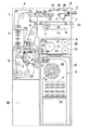
図1は本発明を適用する紙葉類処理機の一例として紙幣入金機の場合を示す略示断面図で、この入金機は、複数枚の紙幣を一括して受入れ、次いで1枚ずつ繰出したのち識別を行い、偽紙幣、傷みの激しい紙幣等の不良紙幣は返却し、正常な紙幣は取込んで保留するものである。そして入金者によって承認されれば保留紙幣を紙幣収納部に収納し、承認されなければ返却する機械である。
【0012】
その構成は、機体1の前面上部に複数枚の紙幣を重ねて一括挿入する紙幣受入口2があり、この紙幣受入口2の内部後方には受入口2を通じて一括挿入される紙幣を受入れてその紙幣を1枚ずつ後方へ繰出す本発明の紙葉類取込み装置である紙幣取込み装置3(詳細は後述する)が配設される。
【0013】
上記紙幣取込み装置3の後方には、該取込み装置3から1枚ずつ繰出される紙幣を搬送する識別搬送路4が配設され、この搬送路4の途中には紙幣の真偽、正損等を判別する識別部5が設けられ、この識別部5の下流の搬送路6は機体1の前方に向け一旦屈曲されたのち上方に折返されて、前記紙幣取込み装置3の下方に配置された紙幣返却部7、紙幣の一時保留部8、紙幣の収納部9の各入口部に連なる搬送路10,11,12へ送路を切換える切換爪を有する第1〜第3分岐部13,14,15が設けられている。
【0014】
上記紙幣返却部7は、紙幣を1枚ずつ受入れて集積させる集積空間16の入口部に弾性を有する羽根が放射状に植設された羽根車17が紙幣の送入に連動して回転駆動自在に設けられ、集積空間16の底板18上に送入される紙幣の後端を羽根で押え、後続紙幣の先端が先行紙幣の後端に当らないようにしてジャムを起さないようになっている。
【0015】
また上記底板18は昇降自在とされ、集積空間16の上方位置にはベルト19が水平方向に配設されていて、底板18上に集積された紙幣を底板18の上昇によりベルト19に押し当て、該ベルト19の駆動によりその紙幣を返却口20へ一括して送出するようになっている。
【0016】
前記一時保留部8は、内部の略中央位置に正逆回転自在で周面に紙幣が巻付けられる単一の回転ドラム21が軸支され、この回転ドラム21の周縁に2種のテープ22,23が共に巻付けられ、これらテープのうち一方のテープ22は入出口部の内側上部に位置するプーリー24、中間プーリー25を経由して巻取軸26に巻付けられ、他方のテープ23は前記入出口部の内側下部に位置するプーリー27を経由して別の巻取軸28に巻付けられている。
【0017】
したがって紙幣を収納するときは、回転ドラム21が正転(図1において矢印方向に回転)して入出口部から送入される紙幣をテープ22,23間に挟み込み、回転ドラム21の周面に順次巻付けて収納し、紙幣を繰出すときは回転ドラム21が逆転駆動(矢印とは反対方向に回転)してテープ22,23間に挟持されていた紙幣をプーリー24,27間から入出口部へ送出するようになっている。
【0018】
前記収納部9はカセット構造とされていて、機体に対し着脱可能とされ、そのカセット30の内部上方の入口部31に近い位置には弾性を有する羽根が放射方向に植設された羽根車32が回転駆動自在に設けられ、この羽根車32の下方には上面に紙幣を集積する底板33が上下動作自在に設けられており、入口部31から送入される紙幣は羽根車32の羽根間に受止められ、しごき板34により底板33上にしごき落されて整然と集積されるようになっている。図中Pは紙幣を示す。また符号35の部分はモータ等の機器類が納められるスペースである。
【0019】
次に前述の紙幣取込み装置3の具体的構成例を図2〜図4を参照して説明する。
【0020】
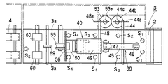
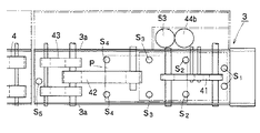
上記紙幣取込み装置3は、複数枚(10枚程度)重ねられた紙幣Pを受入れ得る厚みおよび紙幣Pの短手方向長さより若干大きい幅を有する前記の紙幣受入口2の内方に、取扱う紙幣Pの搬送方向(通常長手方向)の長さより若干長い搬送方向長さを有して重ねられた複数枚の紙幣Pを一括して収容し得る受入空間部36が設けられ、この受入空間部36の下流端には紙幣Pを1枚ずつ繰出す繰出し手段37を備えた繰出口38が設けられている。また上記受入空間部36の上流端近傍には挟持手段39が、上記繰出口38の近傍には押付け手段40がそれぞれ設けられ、これらの下部には搬送手段(第1搬送ベルト41、第2搬送ベルト42)が配設されており、繰出口38の下流は前記識別搬送路4に続き、紙幣を1枚ずつ該搬送路4へ受け渡すようになっている。
【0021】
前記搬送手段の詳細は、前記受入空間部36の底面を構成するように該空間部36の幅方向中央位置にその上流端近傍から搬送方向略中央位置にかけて配設される前述の第1搬送ベルト41と、この搬送ベルト41の下流端に対し若干間隔をおいた位置から繰出し側の搬送路(第3搬送路43)の幅方向中央位置にかけて配設される前述の第2搬送ベルト42とを有し、これら第1、第2搬送ベルト41,42は独立して駆動可能とされるとともに正逆両方に回動可能とされている。
【0022】
上記第1搬送ベルト41の上方位置に設けられる前記の挟持手段39は、紙幣搬送方向に対し直交する方向の軸44により中間部が枢支された揺動部材45を有し、この揺動部材45の前記受入口2側の端部には挟持ローラ46が回転自在に軸着され、反対端には従動ローラ47が左右一対として回転自在に軸着されたもので、上記軸44の一端にはリンク部材44aの一端が固着され、このリンク部材44aの他端はソレノイド44bのプランジャ44cに枢着されていて、ソレノイド44bの励磁時には前記挟持ローラ46が第1搬送ベルト41の上面に押しつけられ、消磁時には従動ローラ47が第1搬送ベルト41の両側部分に押しつけられるようになっている。
【0023】
なお上記挟持ローラ46の位置は、該ローラ46から前記繰出口38までの距離が紙幣Pの搬送方向長さよりも若干長くなる位置とされている。
【0024】
前記受入口2の内方近傍位置で前記挟持ローラ46の直前位置には、検知ラインが紙幣搬送面と交差するように光学式のセンサ(第1センサS1 )が配設され、また前記軸44と従動ローラ47との間の位置には同様のセンサ(第2センサS2 )が配設されている。
【0025】
前記繰出口38の近傍に設けられる押付け手段40は、前記第1搬送ベルト41の下流端近傍の上方位置で、紙幣搬送方向に直交する方向の軸48により基端が枢支された揺動部材49を有し、この揺動部材49の先端には押え板50の上面の搬送方向略中央位置が軸51により揺動自在に支持されたもので、前記軸48の一端にはリンク部材48aの一端が固着され、このリンク部材48aの他端はソレノイド53のプランジャ53aに枢着されていて、ソレノイド53の励磁時には前記押え板50が第2搬送ベルト42の上面に押しつけられ、消磁時には上昇離間するようになっている。
【0026】
上記押え板50は搬送方向にある程度の長さを有しており、この押え板50が第2搬送ベルト42の上面に押しつけられるとき搬送方向にそって広い範囲にわたって押えられ、したがって紙幣Pの先端位置が多少ずれた位置にあっても確実に紙幣Pを第2搬送ベルト42の上面に押しつけることができるようになされており、その上流端は若干上向きに屈曲されている。
【0027】
前記軸48の位置より搬送方向下流側には前記と同様のセンサ(第3センサS3 )が配設されている。
【0028】
前記繰出し手段37は、第2搬送ベルト42の上部走行側を挟んで下側に位置するローラ54と、その上側に位置してゲート部材を構成する逆転ローラ55とで構成され、この逆転ローラ55の周面は第2搬送ベルト42より摩擦係数が小さく設定され、紙幣Pを受入空間36側へ戻す方向に回転駆動される。したがって第2搬送ベルト42に接して搬送される紙幣Pが繰出口38へ送り込まれると、逆転ローラ55による戻し力よりも第2搬送ベルト42による搬送力の方が大きいので紙幣Pは第3搬送路43側へ繰出され、紙幣Pが複数枚重なっていると第2搬送ベルト42に接している最下位の紙幣Pのみが搬送され、それより上位の紙幣Pは逆転ローラ55の回転によって受入空間36内に戻され、1枚のみの通過を果すことになる。
【0029】
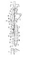
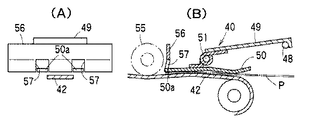
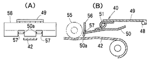
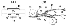
前記逆転ローラ55の直前位置には、下端と第2搬送ベルト42の上面との間に紙幣Pが通過可能な間隙をおいて規制板56が固設され、この規制板56の下端縁に図5〜図7に示すように形成された切欠部57,57に前記押え板50の端部50aが係合することにより押え板50の下流端の移動範囲が規制され、上方に跳ね上がらないようになっている。
【0030】
前記第2搬送ベルト42の下流端のプーリー58および第3搬送ベルト43の上部には従動ローラ59,60が設けられている。
【0031】
そして前記規制板56の直前位置、および前記第3搬送ベルト43の下流端近傍位置には前記と同様のセンサ(第4センサS4 、第5センサS5 )がそれぞれ配設されている。
【0032】
次に作用を説明する。
【0033】
まず図1に示した紙幣入金機の全体の作用の概略について説明すると、複数枚の紙幣が重ねた状態で受入口2に挿入されると一括して紙幣取込み装置3に取込まれたのち1枚ずつ繰出されて識別搬送路4を通り識別部5へ送られ、その紙幣の真偽、金種、正損が識別される。
【0034】
その識別の結果、異常紙幣(偽紙幣、外国紙幣、傷みが激しく識別不能の紙幣等)がある場合は、搬送路6から返却搬送路10を経て返却部7へ送り込まれ、底板18上へ集積される。一方正常な紙幣であれば第2分岐部14を経て一時保留部8へ送り込まれ、テープ22,23間に挟まれて回転ドラム21に巻付けられて一時保留される。
【0035】
受入口2に挿入されたすべての紙幣の識別が完了して所定の箇所に振り分けられると、返却部7に送入された異常紙幣は返却口20からまとめて返却され、利用者に戻される。
【0036】
返却後、利用者による「承認」または「非承認」操作が行われると、一時保留部8の巻取軸26,28が駆動されてテープ22,23が回転ドラム21からほどかれ、それぞれ巻取軸26,28に巻取られる間にテープ22,23間に挟まれていた紙幣は順次搬送路へ送出される。
【0037】
上記「承認」の操作が行われた場合は、第3分岐部15の切換爪は紙幣を後方へ振り分ける位置をとり、紙幣は第2および第1分岐部13を経由して収納部9であるカセット30内に送り込まれて収納される。
【0038】
また「非承認」の操作が行われた場合は、第3分岐部15の切換爪は紙幣を後方へ振り分ける位置をとり、紙幣は返却部7へ搬送される。この紙幣は底板18上に集積されたのち底板18の上昇によりベルト19の駆動で返却口20から一括返却される。
【0039】
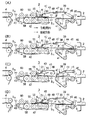
次に本発明に係る取込み装置3の作用の詳細につき図8〜図10を参照して説明する。
【0040】
待機状態においては、ソレノイド44b,53はいずれも非励磁状態にあり、挟持手段39の挟持ローラ46は第1搬送ベルト41の上面に接し、押付け手段40の押え板50も第2搬送ベルト42の上面に接しておかれている。また各ベルト41,42,43および逆転ローラ55は停止している(図8(A))。
【0041】
利用者によって重ねられた複数枚の紙幣Pが受入口2に挿入され、その先端が第1センサS1 の検知ラインを遮切って紙幣の挿入が検知されると、その信号により挟持手段39のソレノイド44bが励磁され、揺動部材45が軸44を中心として図において反時計方向に揺動し、これにより挟持ローラ46は図8(B)のように上昇する。
【0042】
これにより紙幣Pの挿入の妨げがなくなり、紙幣Pをさらに挿入すると、その先端が第2センサS2 により検知され、その信号により挟持手段39のソレノイド44bが消磁されて挟持ローラ46が下降するとともに第1搬送ベルト41が正転駆動(紙幣送り込み方向駆動)する(図8(C))。これにより挿入された紙幣は第1搬送ベルト41の上面と挟持ローラ46とで挟まれて搬送される。
【0043】
このとき紙幣Pはその上面の幅方向中央付近の1点が挟持ローラ46により押えられている形であり(図10(A))、その挟持点を中心として左右に回転が可能な状態であるから、紙幣Pの挿入方向が多少曲っていても装置の側壁3a部分で紙幣Pの側端部が押されることによって直進姿勢に矯正される(図10(B)〜(C))。そして矯正後は挟持手段39の従動ローラ47,47が左右一対として設けられているので直進状態が保たれる。
【0044】
こうして搬送される紙幣Pの先端が第3センサS3 によって検知されると、押付け手段40のソレノイド53が励磁されて押え板50が上昇するとともに、第2搬送ベルト42、第3搬送ベルト43が正転駆動し、逆転ローラ55の駆動が開始される(図8(D))。
【0045】
次いで紙幣Pの先端が第4センサS4 により検知されると、押付け手段40のソレノイド53が消磁するとともに第1搬送ベルト41の駆動が停止する。このソレノイド53の消磁により押え板50が下降し、紙幣Pを第2搬送ベルト42の上面に押しつける(図9(A))。
【0046】
この状態に至ると、最下位の紙幣Pは第2搬送ベルト42との摩擦によって繰出口38から繰出され、その紙幣Pの上に重なっている紙幣は紙幣間の摩擦によって繰出されようとしても逆転ローラ55の逆方向回転によって受入空間部36側へ戻される。
【0047】
上記のようにして繰出された紙幣Pは第2搬送ベルト42に引続いて第3搬送ベルト43を搬送されて識別搬送路4へ受渡され、識別部5へ送られる。
【0048】
一方、先端が跳ね上がる方向に折りぐせが付いている紙幣が挿入された場合にその紙幣Pの先端により押え板50の下流端が上方へ持ち上げられるが、この押え板50の下流端50aは規制板56の切欠部57,57によってその上昇が抑えられるので持ち上げられることがない(図7)。また繰出し動作中は挟持ローラ46が下降位置におかれているので、受入口2に紙幣Pが追加挿入されることはない。
【0049】
上記のようにして受入空間部36内に一括して受入れた紙幣Pが順次繰出され、すべてのセンサS1 〜S5 が透光状態になると、挿入された紙幣Pのすべてが取込まれたものと判断し、第2、第3搬送ベルト42,43の駆動が停止し、図8(A)の待機状態に戻る。
【0050】
紙幣挿入時に、第2センサS2 が紙幣Pの挿入を検知し、挟持ローラ46と第1搬送ベルト41とで紙幣Pを挟持したのち第1搬送ベルト41が正転駆動を開始したにも拘らず所定時間内に第3センサS3 が紙幣を検知しない場合は、搬送異常が発生したものと判断して第1搬送ベルト41を逆転駆動して紙幣の返却を図る。
【0051】
受入口2に返却された紙幣Pが利用者によって抜きとられることにより第1センサS1 が透光状態に移行すれば待機状態に戻る。第4センサS4 についても同様に、上流側のセンサが紙幣Pを検知し、搬送手段を駆動させたにも拘らず所定時間以内に次位のセンサが紙幣を検知しない場合は搬送手段を逆転させて紙幣の返却を図る。この逆転駆動によっても上流側のセンサが透光状態に戻らない場合はメカダウンする。
【0052】
紙幣がきちんと整列されていず、前後にずれた状態のまま受入口2に挿入されることがある。このような場合においても紙幣Pの先端が第4センサS4 が検知するまでは前述した通常の場合と同様に作用する。
【0053】
すなわち搬送される紙幣Pの先端が第4センサS4 により検知されると、押付け手段40のソレノイド53が消磁されるとともに第1搬送ベルト41の駆動が停止する。このとき後方に大きくずれて挿入された紙幣Pは第1搬送ベルト41と挟持ローラ46とで挟持された状態になっている。次いで押付け手段40のソレノイド53の消磁により押え板50が下降し、紙幣Pを第2搬送ベルト42の上面に押しつける。こうして最下位の紙幣Pは第2搬送ベルト41によって繰出口38から繰出され、該紙幣につられて繰出されようとする上位の紙幣は逆転ローラ55によって受入空間部36側へ戻される。
【0054】
前述の第1搬送ベルト41と挟持ローラ46とで挟持されている紙幣Pは繰出されることなく受入空間部36内に残る。この場合、繰出口38と挟持ローラ46との間の距離が紙幣の搬送方向長さよりも長く設定されていることから、挟持される紙幣Pの先端は繰出口38に達していない。そのため挟持されている紙幣Pの上位の紙幣が先行して挟持されていない場合、上位の紙幣が第2搬送ベルト42に接触し、繰出されることになる。したがって受入空間部36内に受入れられている紙幣のうち、第1搬送ベルト41と挟持ローラ46により挟持されていない紙幣のみが繰出される。
【0055】
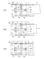
また、第2センサS2 が紙幣Pを検知していながら第5センサS5 が紙幣Pを検知しない状態が所定時間以上継続すると、挟持ローラ46により挟持されていない紙幣Pはすべて繰出され、挟持されている紙幣Pのみが残留しているものと判断される(図9(B))。すると挟持手段39のソレノイド44bおよび押付け手段40のソレノイド53が励磁されるとともに第1搬送ベルト41が正転駆動される(図9(C))。
【0056】
上記ソレノイド44bの励磁に伴って挟持ローラ46が上昇するとともに従動ローラ47が下降し、挟持されていた紙幣Pが解放されて従動ローラ47と第1搬送ベルト41とによって搬送される。そして前記ソレノイド53の励磁によって押え板50が上昇し、上記紙幣は第2搬送ベルト42上へ送り込まれる。
【0057】
上記の紙幣Pの先端が第4センサS4 により検知されると、押付け手段40のソレノイド53が消磁し(図9(D))、これに伴い押え板50が下降して紙幣Pが第2搬送ベルト42の上面に押しつけられ、最下位の紙幣Pが第2搬送ベルト42によって繰出される。この場合も、上位の紙幣の連れ出しは逆転ローラ55により阻止され、受入空間部36へ戻される。
【0058】
繰出された紙幣Pは識別搬送路4を通って識別部5へ送られ、識別される。このとき挟持ローラ46は下降位置にあるので受入口2からの紙幣の追加挿入はできない。
【0059】
受入空間部36内の紙幣が順次繰出され、すべてのセンサS1 〜S5 が透光状態になると、受入れた紙幣Pのすべてが繰出されたものと判断し、挟持手段39のソレノイド44bが消磁され第2,第3搬送ベルト41,42が共に停止されている待機状態に戻る(図8(A))。
【0060】
なお、上記取込み装置3においては、受入空間部36内の紙幣を繰出口38に送り込む搬送機構と、紙幣を繰出す繰出手段とが単一の部材(第2搬送ベルト42)によって構成した場合について示したが、搬送ベルトと繰出ローラとの組合わせのように別個の部材を配置したものであってもよい。
【0061】
【発明の効果】
以上説明したように本発明によれば、紙葉類間の摩擦力が大きい紙葉類を複数枚重ねて挿入された場合であっても、その紙葉類を確実に1枚ずつ繰出すことができ、また装置の設置姿勢は縦横無関係であるから紙葉類処理装置内へ組込む際のレイアウトに制約を受けることがない。
【図面の簡単な説明】
【図1】本発明を適用した紙葉類処理機の一例を示す略示断面図。
【図2】本発明に係る紙葉類取込み装置の一実施形態を示す側面図。
【図3】同、平面図。
【図4】同、下面図。
【図5】図2における規制板と押え板との関係を示すもので、(A)は通常の紙幣を押えた状態の正面図、(B)は断面図。
【図6】同、(A)は紙幣を押えていない状態の正面図、(B)は断面図。
【図7】同、(A)は折りぐせの付いた紙幣を押えた状態の正面図、(B)は断面図。
【図8】(A)〜(D)は作用を示す説明図。
【図9】(A)〜(D)は作用を示す説明図。
【図10】(A)〜(C)は紙幣が斜め姿勢に挿入された場合の矯正状況を示す説明図。
【符号の説明】
1 機体
2 紙幣受入口
3 紙幣取込み装置
5 識別部
7 紙幣返却部
8 一時保留部
9 収納部
20 返却口
30 カセット
36 受入空間部
37 繰出し手段
38 繰出口
39 挟持手段
40 押付け手段
41 第1搬送ベルト
42 第2搬送ベルト
43 第3搬送ベルト
46 挟持ローラ
47 従動ローラ
44b,53 ソレノイド
50 押え板
55 逆転ローラ
56 規制板[0001]
BACKGROUND OF THE INVENTION
The present invention relates to a paper sheet processing machine, and more particularly, to a paper sheet taking-in device in a paper sheet processing machine that receives a plurality of stacked paper sheets at a time and then feeds them one by one to perform a required process. .
[0002]
[Prior art]
In the case of a processor that performs paper sheets, especially bill counting, sorting, storage, and other necessary processing, it accepts a plurality of stacked bills in a lump and then feeds them one by one to perform the required processing. There is a paper sheet processing machine.
[0003]
In the above-described machine, when a plurality of stacked paper sheets are received collectively, the paper sheets are not necessarily aligned, and in particular, a paper sheet close to the feeding means for feeding one by one. When the next paper sheet precedes the paper sheet, the next paper sheet is first fed out, and the adjacent paper sheet is fed out from the middle, resulting in a feeding failure.
[0004]
In order to solve such a problem, a paper sheet taking-in device (Japanese Patent Laid-Open No. 7-315612) has been proposed in which an accepted paper sheet is aligned and a feeding operation is started.
[0005]
The apparatus disclosed in this publication accepts a plurality of stacked paper sheets in a batch in a positioning tray, vibrates the tray, aligns the paper sheets in the tray, and then attaches to the tray. The sheet is fed one sheet at a time by the conveyed roller.
[0006]
[Problems to be solved by the invention]
However, in the above-described conventional apparatus, if the state of the paper sheet is good (for example, a new bill), the paper sheet is moved downward and aligned by applying vibration to the alignment tray. If the leaf is a paper sheet with a wrinkle like a circulation banknote, the friction between the paper sheets is large, so it is not always possible to obtain a good alignment state simply by applying vibration, and this causes a feeding failure. There is a problem.
[0007]
In addition, since it is based on the idea of aligning the paper sheets in the alignment tray by vibration, a receiving space for receiving the paper sheets must be provided in the vertical direction, which limits the layout and allows freedom in design. There is a problem that becomes low.
[0008]
[Means for Solving the Problems]
The present invention can reliably feed out the sheets one by one even when a plurality of sheets having a large friction between the sheets are put in a pile. An object of the present invention is to provide a paper sheet take-in device that can horizontally arrange a receiving space for leaves and can increase the degree of freedom in layout.
[0009]
As a means for solving the above-mentioned problems, the present invention collectively collects stacked paper sheets that are a plurality of stacked paper sheets having a length in the transport direction that is slightly longer than the transport direction length of the paper sheets to be handled. A receiving space portion (36) that can be received and accommodated, a paper sheet receiving port (2) that is provided at the upstream end of the receiving space portion (36) in the transport direction and into which stacked paper sheets are inserted, and the receiving space A delivery port (38) provided at the downstream end in the transport direction of the space portion (36) and an area near the upstream end in the transport direction of the receiving space portion (36) and a substantially central position in the transport direction of the receiving space portion (36). The first conveying belt (41) provided and the second conveying belt (42) disposed from the position spaced from the downstream end of the first conveying belt (41) in the conveying direction to the delivery port (38). ) And the second conveyor belt (42) A lower roller (54) located on the lower side of the upper running side, and a reverse rotation roller (55) constituting a gate member located on the upper side of the second conveying belt (42), A feeding means (37) for feeding the stacked paper sheets one by one, and a position in the vicinity of the upstream end of the receiving space (36) in the transport direction, with respect to the upper surface of the first transport belt (41) A position where the distance between the feeding position (38) is slightly longer than the length in the conveyance direction of the paper sheet, and is capable of switching between a holding position where the stacked paper sheets are pressed and a release position where the stacked paper sheets are not held. A pressing roller (46) provided on the pressing roller, a pressing plate (50) switchable between a pressing position for pressing the stacked paper sheets against the second conveying belt (42) and a retracting position for not pressing, and the receiving port. At the position near the inner side of (2), the clamping roller (46) A first sensor provided in the conveying direction shortly before the position (S 1), and a second sensor provided in the conveying direction intermediate position of the first conveyor belt (41) (S 2), the first conveyor in the conveying direction A third sensor (S 3 ) provided between the belt (41) and the second transport belt (42), and the second sensor (S 2 ) at a position downstream in the transport direction from the sandwiching roller (46). ) And the third sensor (S 3 ), and when the sandwiching roller (46) is in the release position, it is in a pressing position pressed against the upper surface of the first transport belt (41), When the clamping roller (46) is in the clamping position, the driven roller (47) in the non-pressing position away from the first conveying belt (41) and the downstream side of the third sensor (S 3 ) in the conveying direction At the upstream side of the outlet (38) A fourth sensor (S 4 ) provided, and a fifth sensor (S 5 ) provided at a downstream position in the transport direction from the delivery port (38),
(A) In the standby state, the first conveyor belt (41), the second conveyor belt (42), and the reverse rotation roller (55) are stopped, the clamping roller (39) is in the clamping position, and the driven The roller (47) is in the non-pressing position, and the pressing plate (50) is in the pressing position,
(B) When the first sensor (S 1 ) detects that the leading edge of the stacked paper sheets has been inserted into the receiving port (2), the clamping roller (46) is set to the release position, The driven roller (47) is in a pressing position,
(C) When the second sensor (S 2 ) detects the leading edge of the stacked paper sheets, the clamping roller (46) is set to the clamping position, the driven roller (47) is set to the non-pressing position, and By driving the first conveyor belt (41) to rotate forward in the paper sheet feeding direction, the stacked paper sheets are conveyed by being sandwiched between the first conveyor belt (41) and the clamping roller (46),
(D) When the third sensor (S 3 ) detects the leading edge of the stacked paper sheets, the presser plate (50) is set to the retracted position and the paper sheets are fed into the second transport belt (42). The forward rotation drive in the direction and the reverse rotation drive of the reverse rotation roller,
(E) When the fourth sensor (S 4 ) detects the leading edge of the stacked sheets, the driving of the first conveying belt (41) is stopped and the pressing plate (50) is set to the pressing position. Thus, the lowest paper sheet among the stacked paper sheets is fed out from the feed outlet (38) by friction with the second transport belt (42), and overlaps the paper sheets. Paper sheets are returned to the receiving space (36) side by the rotation of the reverse rotation roller,
(F) After that, when the second sensor (S 2 ) detects the paper sheet and the fifth sensor (S 5 ) does not detect the paper sheet for a predetermined time or longer, the nipping is performed. Judging that only the paper sheets sandwiched between the rollers (46) remain in the receiving space (36),
(F1) The clamping roller (46) is set to the release position, the driven roller (47) is set to the pressing position, the presser plate (50) is set to the retracted position, and the first conveying belt (41) is driven to rotate forward. Thus, the paper sheets held by the holding roller (46) are conveyed by the driven roller (47) and the first conveying belt (41),
(F2) When the leading edge of the paper sheet is detected again by the fourth sensor (S 4 ), the paper that has been nipped by the nipping roller (46) by setting the pressing plate (50) to the pressing position The lowest paper sheet among the paper sheets is fed out from the feeding outlet (38) by friction with the second conveying belt (42), and the paper sheets overlying the paper sheet are reversed. The roller is returned to the receiving space (36) side by the rotation of the roller,
(G) The first sensor (S 1 ), the second sensor (S 2 ), the third sensor (S 3 ), the fourth sensor (S 4 ), and the fifth sensor (S 5 ) When the state is not detected, the first conveyor belt (41), the second conveyor belt (42), the reverse roller (55), the sandwiching roller (39), the driven roller (47) and the Return the presser plate (50) to the standby state (a).
A paper sheet take-in device for a paper sheet processing machine is provided.
[0010]
DETAILED DESCRIPTION OF THE INVENTION
The present invention will be described below with reference to embodiments shown in the drawings.
[0011]
FIG. 1 is a schematic cross-sectional view showing a case of a banknote depositing machine as an example of a paper sheet processing machine to which the present invention is applied. This depositing machine accepts a plurality of banknotes in a lump and then feeds them one by one. After that, the banknotes are identified, defective banknotes such as fake banknotes and severely damaged banknotes are returned, and normal banknotes are captured and held. And if it is approved by the depositor, the banknote is stored in the banknote storage unit.
[0012]
The structure has a
[0013]
Behind the banknote take-in
[0014]
The banknote return unit 7 is configured such that an impeller 17 in which elastic blades are radially arranged at an entrance of a stacking
[0015]
The
[0016]
The
[0017]
Therefore, when storing banknotes, the
[0018]
The
[0019]
Next, the specific structural example of the above-mentioned banknote taking-in
[0020]
The banknote take-in
[0021]
The details of the transport means are as described above. The first transport belt is disposed at the center position in the width direction of the
[0022]
The clamping means 39 provided at a position above the
[0023]
The position of the pinching
[0024]
An optical sensor (first sensor S 1 ) is disposed in a position near the inside of the receiving
[0025]
The pressing means 40 provided in the vicinity of the
[0026]
The
[0027]
A sensor (third sensor S 3 ) similar to the above is disposed downstream of the position of the
[0028]
The feeding means 37 includes a
[0029]
A restricting
[0030]
Driven
[0031]
Sensors (fourth sensor S 4 , fifth sensor S 5 ) similar to those described above are disposed immediately before the
[0032]
Next, the operation will be described.
[0033]
First, the outline of the overall operation of the banknote deposit machine shown in FIG. 1 will be described. When a plurality of banknotes are stacked and inserted into the receiving
[0034]
As a result of the identification, if there are abnormal banknotes (fake banknotes, foreign banknotes, banknotes that are severely indistinguishable, etc.), they are sent from the
[0035]
When the identification of all the banknotes inserted into the receiving
[0036]
When the user performs an “approval” or “non-approval” operation after the return, the take-up
[0037]
When the “approval” operation is performed, the switching claw of the third branching portion 15 takes a position for sorting the bills backward, and the bill is the
[0038]
When the “non-approval” operation is performed, the switching claw of the third branching unit 15 takes a position for sorting the bills backward, and the bills are conveyed to the return unit 7. The banknotes are collected on the
[0039]
Next, details of the operation of the
[0040]
In the standby state, both the
[0041]
When a plurality of banknotes P stacked by the user are inserted into the receiving
[0042]
This eliminates interfere with insertion of the banknotes P, when further inserted banknotes P, with its leading end is detected by the second sensor S 2, the
[0043]
At this time, the bill P has a shape in which one point in the vicinity of the center in the width direction of the top surface is pressed by the sandwiching roller 46 (FIG. 10A), and the bill P can be rotated left and right around the sandwiching point. Therefore, even if the insertion direction of the bill P is slightly bent, the side end portion of the bill P is pushed at the
[0044]
Thus the leading edge of the banknote P conveyed is detected by the third sensor S 3, together with the
[0045]
Next, when the leading edge of the banknote P is detected by the fourth sensor S 4 , the
[0046]
When this state is reached, the lowest banknote P is fed out from the
[0047]
The bills P fed out as described above are conveyed on the
[0048]
On the other hand, when a banknote with a fold is inserted in the direction in which the front end is flipped up, the downstream end of the
[0049]
When the banknotes P received collectively in the receiving
[0050]
When the bill is inserted, the second sensor S 2 Detects the insertion of the banknote P, and after the banknote P is sandwiched between the sandwiching
[0051]
The first sensor S 1 by the returned banknotes P to the receiving
[0052]
The banknotes may not be properly aligned and may be inserted into the receiving
[0053]
That is, the leading end of the paper money P conveyed is detected by the fourth sensor S 4, the drive along with the
[0054]
The bills P sandwiched between the first conveying
[0055]
Further, when the state in which the second sensor S 2 is detecting the banknote P and the fifth sensor S 5 does not detect the banknote P continues for a predetermined time or longer, all the banknotes P not held by the holding
[0056]
With the excitation of the
[0057]
When the leading end of the paper money P is detected by the fourth sensor S 4, the
[0058]
The fed banknote P is sent to the
[0059]
When the banknotes in the receiving
[0060]
In addition, in the said taking-in
[0061]
【The invention's effect】
As described above, according to the present invention, even when a plurality of paper sheets having a large frictional force between the paper sheets are inserted in a stacked manner, the paper sheets are reliably fed out one by one. In addition, since the installation posture of the apparatus is irrelevant vertically and horizontally, there is no restriction on the layout when incorporating the apparatus into the paper sheet processing apparatus.
[Brief description of the drawings]
FIG. 1 is a schematic cross-sectional view showing an example of a paper sheet processing machine to which the present invention is applied.
FIG. 2 is a side view showing an embodiment of a paper sheet taking-in device according to the present invention.
FIG. 3 is a plan view of the same.
FIG. 4 is a bottom view of the same.
5A and 5B show a relationship between a regulating plate and a presser plate in FIG. 2, in which FIG. 5A is a front view showing a state where a normal banknote is pressed, and FIG. 5B is a cross-sectional view.
6A is a front view of a state in which a bill is not pressed, and FIG. 6B is a cross-sectional view.
FIG. 7A is a front view showing a state where a folded banknote is pressed, and FIG. 7B is a cross-sectional view.
FIGS. 8A to 8D are explanatory views showing the operation.
FIGS. 9A to 9D are explanatory views showing the operation. FIGS.
FIGS. 10A to 10C are explanatory views showing a correction situation when a bill is inserted in an oblique posture.
[Explanation of symbols]
DESCRIPTION OF
Claims (1)
この受入空間部(36)の搬送方向上流端に設けられ、重積紙葉類が挿入される紙葉類受入口(2)と、
前記受入空間部(36)の搬送方向下流端に設けられた繰出口(38)と、
前記受入空間部(36)の搬送方向上流端近傍から前記受入空間部(36)の搬送方向略中央位置にかけて配設された第1搬送ベルト(41)と、
この第1搬送ベルト(41)の搬送方向下流端に対し間隔をおいた位置から前記繰出口(38)にかけて配設された第2搬送ベルト(42)と、
前記繰出口(38)に設けられ、前記第2搬送ベルト(42)の上部走行側の下側に位置する下側ローラ(54)と、前記第2搬送ベルト(42)の上部走行側の上側に位置してゲート部材を構成する逆転ローラ(55)とを有し、重積紙葉類を紙葉類1枚ずつ繰り出す繰出し手段(37)と、
前記受入空間部(36)の搬送方向上流端近傍位置に配置され、前記第1搬送ベルト(41)の上面に対して押し付けられて重積紙葉類を挟持する挟持位置と、挟持しない解放位置とに切換え可能とされ、繰出口(38)との間の距離が紙葉類の搬送方向長さより若干長くなる位置に設けられた挟持ローラ(46)と、
重積紙葉類を前記第2搬送ベルト(42)に押し付ける押圧位置と、押し付けない退避位置とに切換え可能な押え板(50)と、
前記受入口(2)の内方近傍位置で、前記挟持ローラ(46)の搬送方向直前位置に設けられた第1センサ(S1)と、
前記第1搬送ベルト(41)の搬送方向途中位置に設けられた第2センサ(S2)と、
搬送方向における前記第1搬送ベルト(41)と前記第2搬送ベルト(42)との間に設けられた第3センサ(S3)と、
前記挟持ローラ(46)より搬送方向後流側位置で前記第2センサ(S2)と前記第3センサ(S3)との間に位置し、前記挟持ローラ(46)が解放位置にあるときは、前記第1搬送ベルト(41)の上面に押し付けられる押付位置にあり、前記挟持ローラ(46)が挟持位置にあるときは、前記第1搬送ベルト(41)から離れた非押付位置にある従動ローラ(47)と、
搬送方向において前記第3センサ(S3)より下流側で前記繰出口(38)より上流側に設けられた第4センサ(S4)と、
前記繰出口(38)より搬送方向下流位置に設けられた第5センサ(S5)と、
を備え、
(a)待機状態においては、前記第1搬送ベルト(41)、前記第2搬送ベルト(42)および前記逆転ローラ(55)は停止しており、前記挟持ローラ(39)は挟持位置、前記従動ローラ(47)は非押付位置、前記押え板(50)は押圧位置にあり、
(b)前記受入口(2)へ重積紙葉類の先端が挿入されたことが前記第1センサ(S1)によって検知された時、前記挟持ローラ(46)を解放位置とするとともに、前記従動ローラ(47)を押付位置とし、
(c)前記第2センサ(S2)が重積紙葉類の先端を検知した時、前記挟持ローラ(46)を挟持位置とし、前記従動ローラ(47)を非押付位置とするとともに、前記第1搬送ベルト(41)を紙葉類送り込み方向へ正転駆動することで、重積紙葉類を前記第1搬送ベルト(41)と前記挟持ローラ(46)で挟んで搬送し、
(d)前記第3センサ(S3)が重積紙葉類の先端を検知した時、前記押え板(50)を退避位置とするとともに、前記第2搬送ベルト(42)の紙葉類送り込み方向への正転駆動と前記逆転ローラの逆転駆動とを行わせ、
(e)前記第4センサ(S4)が重積紙葉類の先端を検知した時、前記第1搬送ベルト(41)の駆動を停止するとともに、前記押え板(50)を押圧位置とすることで、重積紙葉類のうち最下位の紙葉類を前記第2搬送ベルト(42)との摩擦によって前記繰出口(38)から繰出すとともに、その紙葉類の上に重なっている紙葉類は前記逆転ローラの回転によって前記受入空間部(36)側へ戻されるようにし、
(f)その後、前記第2センサ(S2)が紙葉類を検知していながら前記第5センサ(S5)が紙葉類を検知しない状態が所定時間以上継続した場合には、前記挟持ローラ(46)で挟持されている紙葉類のみが前記受入空間部(36)内に残留しているものと判断して、
(f1)前記挟持ローラ(46)を解放位置とし、前記従動ローラ(47)を押付位置とし、前記押え板(50)を退避位置とするとともに、前記第1搬送ベルト(41)を正転駆動することで、前記挟持ローラ(46)で挟持されていた紙葉類を、前記従動ローラ(47)と前記第1搬送ベルト(41)とによって搬送し、
(f2)再び紙葉類の先端が前記第4センサ(S4)で検知された時、前記押え板(50)を押圧位置とすることで、前記挟持ローラ(46)で挟持されていた紙葉類のうち最下位の紙葉類を前記第2搬送ベルト(42)との摩擦によって前記繰出口(38)から繰出すとともに、その紙葉類の上に重なっている紙葉類は前記逆転ローラの回転によって前記受入空間部(36)側へ戻されるようにし、
(g)前記第1センサ(S1)、前記第2センサ(S2)、前記第3センサ(S3)、前記第4センサ(S4)および前記第5センサ(S5)が紙葉類を検知しない状態となった時に、前記第1搬送ベルト(41)、前記第2搬送ベルト(42)、前記逆転ローラ(55)、前記挟持ローラ(39)、前記従動ローラ(47)および前記押え板(50)を前記(a)待機状態に戻す、
ように構成されたことを特徴とする紙葉類処理機の紙葉類取込み装置。A receiving space (36) having a length in the transport direction slightly longer than the length in the transport direction of the paper sheets to be handled and capable of receiving and storing stacked paper sheets as a plurality of stacked paper sheets in a lump. When,
A paper sheet receiving port (2) that is provided at the upstream end of the receiving space (36) in the transport direction and into which stacked paper sheets are inserted;
A delivery port (38) provided at the downstream end in the transport direction of the receiving space (36);
A first transport belt (41) disposed from the vicinity of the upstream end in the transport direction of the receiving space portion (36) to the substantially central position in the transport direction of the receiving space portion (36);
A second conveyor belt (42) disposed from a position spaced from the downstream end in the conveyance direction of the first conveyor belt (41) to the delivery port (38);
A lower roller (54) provided at the feed outlet (38) and positioned on the lower side of the upper traveling side of the second conveying belt (42), and an upper side of the upper conveying side of the second conveying belt (42) A reversing roller (55) that constitutes a gate member located at a position, and a feeding means (37) for feeding the stacked paper sheets one by one,
A holding position where the receiving space portion (36) is disposed in the vicinity of the upstream end in the conveying direction and is pressed against the upper surface of the first conveying belt (41) to hold the stacked paper sheets; A clamping roller (46) provided at a position where the distance between the feeding port (38) is slightly longer than the length of the paper sheet in the conveyance direction;
A presser plate (50) capable of switching between a pressing position for pressing the stacked paper sheets against the second conveying belt (42) and a retracted position not pressed;
A first sensor (S 1 ) provided at a position in the vicinity of the inner side of the receiving port (2) and immediately before the holding roller (46) in the conveying direction;
A second sensor (S 2 ) provided at an intermediate position in the conveying direction of the first conveying belt (41);
A third sensor (S 3 ) provided between the first transport belt (41) and the second transport belt (42) in the transport direction;
When it is located between the second sensor (S 2 ) and the third sensor (S 3 ) at a position on the downstream side in the transport direction from the sandwiching roller (46), and the sandwiching roller (46) is in the release position. Is in a pressing position pressed against the upper surface of the first conveyor belt (41), and when the clamping roller (46) is in the clamping position, it is in a non-pressing position away from the first conveyor belt (41). A driven roller (47);
A fourth sensor (S 4 ) provided downstream of the third sensor (S 3 ) and upstream of the delivery port (38) in the transport direction;
A fifth sensor (S 5 ) provided at a downstream position in the transport direction from the feed outlet (38);
With
(A) In the standby state, the first conveyor belt (41), the second conveyor belt (42), and the reverse rotation roller (55) are stopped, the clamping roller (39) is in the clamping position, and the driven The roller (47) is in the non-pressing position, and the pressing plate (50) is in the pressing position,
(B) When the first sensor (S 1 ) detects that the leading edge of the stacked paper sheets has been inserted into the receiving port (2), the clamping roller (46) is set to the release position, The driven roller (47) is in a pressing position,
(C) When the second sensor (S 2 ) detects the leading edge of the stacked paper sheets, the clamping roller (46) is set to the clamping position, the driven roller (47) is set to the non-pressing position, and By driving the first conveyor belt (41) to rotate forward in the paper sheet feeding direction, the stacked paper sheets are conveyed by being sandwiched between the first conveyor belt (41) and the clamping roller (46),
(D) When the third sensor (S 3 ) detects the leading edge of the stacked paper sheets, the presser plate (50) is set to the retracted position and the paper sheets are fed into the second transport belt (42). The forward rotation drive in the direction and the reverse rotation drive of the reverse rotation roller,
(E) When the fourth sensor (S 4 ) detects the leading edge of the stacked sheets, the driving of the first conveying belt (41) is stopped and the pressing plate (50) is set to the pressing position. Thus, the lowest paper sheet among the stacked paper sheets is fed out from the feed outlet (38) by friction with the second transport belt (42), and overlaps the paper sheets. Paper sheets are returned to the receiving space (36) side by the rotation of the reverse rotation roller,
(F) After that, when the second sensor (S 2 ) detects the paper sheet and the fifth sensor (S 5 ) does not detect the paper sheet for a predetermined time or longer, the nipping is performed. Judging that only the paper sheets sandwiched between the rollers (46) remain in the receiving space (36),
(F1) The clamping roller (46) is set to the release position, the driven roller (47) is set to the pressing position, the presser plate (50) is set to the retracted position, and the first conveying belt (41) is driven to rotate forward. Thus, the paper sheets held by the holding roller (46) are conveyed by the driven roller (47) and the first conveying belt (41),
(F2) When the leading edge of the paper sheet is detected again by the fourth sensor (S 4 ), the paper that has been nipped by the nipping roller (46) by setting the pressing plate (50) to the pressing position The lowest paper sheet among the paper sheets is fed out from the feeding outlet (38) by friction with the second conveying belt (42), and the paper sheets overlying the paper sheet are reversed. The roller is returned to the receiving space (36) side by the rotation of the roller,
(G) The first sensor (S 1 ), the second sensor (S 2 ), the third sensor (S 3 ), the fourth sensor (S 4 ), and the fifth sensor (S 5 ) When the state is not detected, the first conveyor belt (41), the second conveyor belt (42), the reverse roller (55), the sandwiching roller (39), the driven roller (47) and the Return the presser plate (50) to the standby state (a).
A paper sheet take-in device of a paper sheet processing machine, characterized in that it is configured as described above.
Priority Applications (1)
| Application Number | Priority Date | Filing Date | Title |
|---|---|---|---|
| JP29734997A JP3649879B2 (en) | 1997-10-29 | 1997-10-29 | Paper sheet take-in device in paper sheet processing machine |
Applications Claiming Priority (1)
| Application Number | Priority Date | Filing Date | Title |
|---|---|---|---|
| JP29734997A JP3649879B2 (en) | 1997-10-29 | 1997-10-29 | Paper sheet take-in device in paper sheet processing machine |
Publications (2)
| Publication Number | Publication Date |
|---|---|
| JPH11130275A JPH11130275A (en) | 1999-05-18 |
| JP3649879B2 true JP3649879B2 (en) | 2005-05-18 |
Family
ID=17845369
Family Applications (1)
| Application Number | Title | Priority Date | Filing Date |
|---|---|---|---|
| JP29734997A Expired - Fee Related JP3649879B2 (en) | 1997-10-29 | 1997-10-29 | Paper sheet take-in device in paper sheet processing machine |
Country Status (1)
| Country | Link |
|---|---|
| JP (1) | JP3649879B2 (en) |
Families Citing this family (1)
| Publication number | Priority date | Publication date | Assignee | Title |
|---|---|---|---|---|
| JP2018162134A (en) * | 2017-03-24 | 2018-10-18 | 沖電気工業株式会社 | Medium processing device |
-
1997
- 1997-10-29 JP JP29734997A patent/JP3649879B2/en not_active Expired - Fee Related
Also Published As
| Publication number | Publication date |
|---|---|
| JPH11130275A (en) | 1999-05-18 |
Similar Documents
| Publication | Publication Date | Title |
|---|---|---|
| US5295675A (en) | Sheet handling apparatus having controlled pressure rolls to ensure feeding of a single sheet | |
| JP3649879B2 (en) | Paper sheet take-in device in paper sheet processing machine | |
| JP3591292B2 (en) | Media holding device | |
| JP2002348016A (en) | Paper sheet storage device and transaction processing device | |
| JPH1171055A (en) | Paper sheet stacking device | |
| JPH08268617A (en) | Paper takeup and delivery device | |
| JPH0718660Y2 (en) | Banknote conveyor | |
| JP3286546B2 (en) | Banknote handling machine | |
| JP2572485B2 (en) | Dispensing and dispensing control device for banknote pay-in / pay-out machine | |
| JP4835194B2 (en) | Banknote handling equipment | |
| JPH05132183A (en) | Paper sheet separating and feeding device, control method thereof, and automatic cash transaction device using the same | |
| JP3901560B2 (en) | Paper sheet processing equipment | |
| JPH0438652B2 (en) | ||
| JPS6224340B2 (en) | ||
| JPH0948552A (en) | Device for accumulating and carrying a variety of paper | |
| JPH10129915A (en) | Paper sheet stacking device | |
| JPS6215914B2 (en) | ||
| KR20250090755A (en) | Medium deposit device | |
| JP3556468B2 (en) | Sheet transport device of sheet processing machine | |
| JP4034552B2 (en) | Banknote processing apparatus and banknote dispensing apparatus | |
| KR20250090728A (en) | Media support device of medium deposit machine | |
| JPS6347960Y2 (en) | ||
| JPH08169612A (en) | Paper processing equipment and automatic paper handling machine | |
| WO1992020600A1 (en) | Bank note conveying device and island of game machines | |
| JP2023012729A (en) | Paper sheet storage device |
Legal Events
| Date | Code | Title | Description |
|---|---|---|---|
| A131 | Notification of reasons for refusal |
Free format text: JAPANESE INTERMEDIATE CODE: A131 Effective date: 20040820 |
|
| A521 | Written amendment |
Free format text: JAPANESE INTERMEDIATE CODE: A523 Effective date: 20041019 |
|
| TRDD | Decision of grant or rejection written | ||
| A01 | Written decision to grant a patent or to grant a registration (utility model) |
Free format text: JAPANESE INTERMEDIATE CODE: A01 Effective date: 20050121 |
|
| A61 | First payment of annual fees (during grant procedure) |
Free format text: JAPANESE INTERMEDIATE CODE: A61 Effective date: 20050216 |
|
| R150 | Certificate of patent or registration of utility model |
Free format text: JAPANESE INTERMEDIATE CODE: R150 |
|
| S533 | Written request for registration of change of name |
Free format text: JAPANESE INTERMEDIATE CODE: R313533 |
|
| R350 | Written notification of registration of transfer |
Free format text: JAPANESE INTERMEDIATE CODE: R350 |
|
| FPAY | Renewal fee payment (event date is renewal date of database) |
Free format text: PAYMENT UNTIL: 20090225 Year of fee payment: 4 |
|
| FPAY | Renewal fee payment (event date is renewal date of database) |
Free format text: PAYMENT UNTIL: 20090225 Year of fee payment: 4 |
|
| FPAY | Renewal fee payment (event date is renewal date of database) |
Free format text: PAYMENT UNTIL: 20100225 Year of fee payment: 5 |
|
| FPAY | Renewal fee payment (event date is renewal date of database) |
Free format text: PAYMENT UNTIL: 20100225 Year of fee payment: 5 |
|
| FPAY | Renewal fee payment (event date is renewal date of database) |
Free format text: PAYMENT UNTIL: 20110225 Year of fee payment: 6 |
|
| FPAY | Renewal fee payment (event date is renewal date of database) |
Free format text: PAYMENT UNTIL: 20120225 Year of fee payment: 7 |
|
| FPAY | Renewal fee payment (event date is renewal date of database) |
Free format text: PAYMENT UNTIL: 20120225 Year of fee payment: 7 |
|
| FPAY | Renewal fee payment (event date is renewal date of database) |
Free format text: PAYMENT UNTIL: 20130225 Year of fee payment: 8 |
|
| LAPS | Cancellation because of no payment of annual fees |