JP3649861B2 - Remote control system for biped robot - Google Patents
Remote control system for biped robot Download PDFInfo
- Publication number
- JP3649861B2 JP3649861B2 JP16454297A JP16454297A JP3649861B2 JP 3649861 B2 JP3649861 B2 JP 3649861B2 JP 16454297 A JP16454297 A JP 16454297A JP 16454297 A JP16454297 A JP 16454297A JP 3649861 B2 JP3649861 B2 JP 3649861B2
- Authority
- JP
- Japan
- Prior art keywords
- foot
- leg
- operator
- sphere
- robot
- Prior art date
- Legal status (The legal status is an assumption and is not a legal conclusion. Google has not performed a legal analysis and makes no representation as to the accuracy of the status listed.)
- Expired - Fee Related
Links
Images
Landscapes
- Manipulator (AREA)
- Control Of Position, Course, Altitude, Or Attitude Of Moving Bodies (AREA)
Description
【0001】
【発明の属する技術分野】
本発明は、二足歩行型ロボットの遠隔制御システムに関する。
【0002】
【従来の技術】
ロボットの遠隔制御システムにあっては、ロボットの動作をジョイスティック等の操作子の操作によりロボットに指令するものが従来より知られている。
【0003】
この種のシステムでは、例えば二足歩行型ロボットを前進側に歩行させる際には、オペレータがジョイスティック等の操作子をロボットの前進側に対応する向きに操作し、このとき、例えば該操作子の操作量によって、ロボットの歩幅や歩行速度等を指令する。
【0004】
しかしながら、このようなシステムでは、二足歩行型ロボットの歩行時の各脚体の動作(両脚の着床、離床を交互に繰り返す動作)と、その動作に対応した操作子の操作とは全く異なる形態をとるため、オペレータにとっては、ロボットの脚体の実際の動きが感覚的に判りづらい。例えば、操作子の操作量によって、二足歩行型ロボットの歩幅を指令する場合、ロボットの歩幅が、オペレータが想定した歩幅よりも大きかったり、小さかったりしても、それを操作子の操作量から感覚的にオペレータが知ることは難しい。
【0005】
このため、上記のようなシステムでは、オペレータが意図したロボットの脚体の動作形態と、操作子の操作形態との間にずれを生じやすく、オペレータが意図したロボットの動作を確実にロボットに行わしめるためには、操作子の操作に熟練を要するものとなっていた。
【0006】
また、ロボットの遠隔制御システムでは、オペレータがその全身にマスター装置を装着して、例えば、ロボットを歩行させようとする場合に、オペレータ自身が実際に歩行し、その歩行動作をマスター装置からロボットに指令するようにしたものが知られている。
【0007】
しかしながら、このようなシステムでは、ロボットの移動環境と同じような広さの設備をマスター装置側に設けておかなければならず、その結果、設備上の制約等を受けて、ロボットを広範囲にわたって移動させることが困難なものとなっていた。
【0008】
【発明が解決しようとする課題】
本発明はかかる背景に鑑み、二足歩行型ロボットの歩行等の脚体の動作を行わしめるに際して、オペレータが自身の操作動作によりロボットの脚体の動作を感覚的に認識しつつ、確実にロボットの脚体の所望の動作を行わしめることができると共に、ロボットを広範囲にわたって移動させることができる二足歩行型ロボットの遠隔制御システムを提供することを目的とする。
【0009】
【課題を解決するための手段】
前記課題を解決するための本発明の第1、第2及び第3態様のそれぞれの二足歩行型ロボットの遠隔制御システムは、オペレータの足平の動作に応じた指令に応じて足平部が動くように自律的に姿勢を安定化しながら2本の脚体を動作させて歩行可能な二足歩行型ロボットの遠隔制御システムであって 、オペレータが着座するシートを備えた上体支持機構と、該上体支持機構のシートに着座したオペレータの両足平を載せる回転自在な球体と、オペレータの各足平が前記球体に接地しているか該球体から離反しているかを検出する足平接地/離反検出手段と、前記球体の回転量及び回転方向を検出する球体回転検出手段とを備えていることを特徴とする。本発明の第1態様の遠隔制御システムは、さらに前記足平接地/離反検出手段により前記球体から離反されたことが検出されたオペレータの足平に対応する前記二足歩行型ロボットの脚体を遊脚側の脚体として、オペレータの一方の足平が前記球体から離反されてから該球体上に再び接地されるまでの間に前記球体回転検出手段により検出された、オペレータの他方の足平による前記球体の回転量及び回転方向に応じた該遊脚側の脚体の足平部の、着床側の脚体の足平部の位置を基準とする相対的な着床位置が含まれる前記指令を前記二足歩行型ロボットに与える脚体動作指令手段とを備えていることを特徴とする。本発明の第2態様の遠隔制御システムは、さらに前記足平接地/離反検出手段により前記球体から離反されたことが検出されたオペレータの足平に対応する前記二足歩行型ロボットの脚体を遊脚側の脚体として、オペレータの一方の足平が前記球体から離反されてから該球体上に再び接地されるまでの間に前記球体回転検出手段により検出された、オペレータの他方の足平による前記球体の回転量及び回転方向に応じた該遊脚側の脚体の足平部の、着床側の脚体の足平部の姿勢を基準とする相対的な着床姿勢が含まれる前記指令を前記二足歩行型ロボットに与える脚体動作指令手段を備えていることを特徴とする。本発明の第3態様の遠隔制御システムは、さらに前記足平接地/離反検出手段により前記球体から離反されたことが検出されたオペレータの足平に対応する前記二足歩行型ロボットの脚体を遊脚側の脚体として、オペレータの一方の足平が前記球体から離反されてから該球体上に再び接地されるまでの間に前記球体回転検出手段により検出された、オペレータの他方の足平による前記球体の回転量及び回転方向に応じた該遊脚側の脚体の足平部の、着床側の脚体の足平部の位置を基準とする相対的な着床位置及び着床側の脚体の足平部の姿勢を基準とする相対的な着床姿勢が含まれる前記指令を前記二足歩行型ロボットに与える脚体動作指令手段を備えていることを特徴とする。
【0010】
本発明の第1、第2及び第3態様のそれぞれの遠隔制御システムによれば、前記二足歩行型ロボットを移動させる場合には、前記上体支持機構のシートに着座したオペレータ自身が、該ロボットに行わせようとする該ロボットの脚体の動作で移動するかのようにして、該オペレータの一方の足平を一旦持ち上げて前記球体から離反させた後、その持ち上げた足平を降ろして前記球体上に再び接地させる。さらに、本発明の第1態様の遠隔制御システムによれば、その持ち上げた足平を球体上に降ろした際のオペレータの両足平の位置関係を、該ロボットに行わせようとする該ロボットの脚体の動作形態での該ロボットの持ち上げ側の脚体(遊脚側の脚体)の着床時の両脚体の足平部の位置関係に対応させるようにして、前記球体に接地させている足平を移動させて該球体を回転させる。また、本発明の第2態様の遠隔制御システムによれば、その持ち上げた足平を球体上に降ろした際のオペレータの両足平の姿勢関係を、該ロボットに行わせようとする該ロボットの脚体の動作形態での該ロボットの遊脚側の脚体の着床時の両脚体の足平部の姿勢関係に対応させるようにして、前記球体に接地させている足平を移動させて該球体を回転させる。さらに、本発明の第3態様の遠隔制御システムによれば、その持ち上げた足平を球体上に降ろした際のオペレータの両足平の位置関係及び姿勢関係のそれぞれを、該ロボットに行わせようとする該ロボットの脚体の動作形態での該ロボットの遊脚側の脚体の着床時の両脚体の足平部の位置関係及び姿勢関係のそれぞれに対応させるようにして、前記球体に接地させている足平を移動させて該球体を回転させる。例えば前記ロボットに所望の歩幅で前進歩行を行わせる場合には、オペレータがその両足平を前記球体に対して交互に上げ下げし、この際、球体上に接地させている足平を持ち上げ側の足平(球体から離反させている側の足平)に対して後方に移動させるように球体を回転させると共に、この時の球体の回転量をロボットに行わせようとする歩行形態での歩幅に合わせる(歩幅が大きい程、球体の回転量を多くする)。また、例えば、ロボットの前進側への歩行に際してロボットの遊脚側の脚体の足平部を着床側の脚体の足平部に対して斜めに着床させてロボットの移動方向を変更させるような場合には、オペレータは、その持ち上げ側の足平を球体上に接地させる際に、その足平に対して、球体上に接地させている他方の足平が斜めに向くようにして該球体を斜め方向に回転させる。
【0011】
このような操作をオペレータが行っているとき、本発明の第1態様の遠隔制御システムによれば、前記脚体動作指令手段は、前記足平接地/離反検出手段により前記球体から離反されたことが検出されたオペレータの足平に対応する前記二足歩行型ロボットの脚体を遊脚側の脚体として、オペレータの一方の足平が前記球体から離反されてから該球体上に再び接地されるまでの間に前記球体回転検出手段により検出された、オペレータの他方の足平による前記球体の回転量及び回転方向に応じた該遊脚側の脚体の足平部の、着床側の脚体の足平部の位置を基準とする相対的な着床位置が含まれる前記指令を前記二足歩行型ロボットに与える。また、本発明の第2態様の遠隔制御システムによれば、前記脚体動作指令手段は、前記足平接地/離反検出手段により前記球体から離反されたことが検出されたオペレータの足平に対応する前記二足歩行型ロボットの脚体を遊脚側の脚体として、オペレータの一方の足平が前記球体から離反されてから該球体上に再び接地されるまでの間に前記球体回転検出手段により検出された、オペレータの他方の足平による前記球体の回転量及び回転方向に応じた該遊脚側の脚体の足平部の、着床側の脚体の足平部の姿勢を基準とする相対的な着床姿勢が含まれる前記指令を前記二足歩行型ロボットに与える。さらに本発明の第3態様の遠隔制御システムによれば、前記脚体動作指令手段は、前記足平接地/離反検出手段により前記球体から離反されたことが検出されたオペレータの足平に対応する前記二足歩行型ロボットの脚体を遊脚側の脚体として、オペレータの一方の足平が前記球体から離反されてから該球体上に再び接地されるまでの間に前記球体回転検出手段により検出された、オペレータの他方の足平による前記球体の回転量及び回転方向に応じた該遊脚側の脚体の足平部の、着床側の脚体の足平部の位置を基準とする相対的な着床位置及び着床側の脚体の足平部の姿勢を基準とする相対的な着床姿勢が含まれる前記指令を前記二足歩行型ロボットに与える。このとき、前記球体の回転量や回転方向は、前述の如くオペレータが意図したロボットの脚体の動作形態での該ロボットの遊脚側の脚体の着床時の両脚体の足平部の位置及び姿勢関係のうち一方又は両方に対応するものであるので、該球体の回転量及び回転方向のうち一方又は両方に応じた脚体の着床位置及び姿勢のうち一方又は両方が含まれる指令をロボットに与えることで、ロボットの脚体は、オペレータの球体上での足運びの形態と同じような形態で動作することとなる。
【0012】
従って、本発明の第1、第2及び第3態様のそれぞれの遠隔制御システムによれば、オペレータの足平の動作形態に合わせて、ロボットの脚体が動作することとなり、オペレータは、自身の足平の動きをロボットの脚体の動作として認識することができる。また、オペレータは、その上体を前記上体支持機構に支持した場所で、足平を動かすことで、ロボットを移動させることができるため、広範な操縦設備を必要とすることなく、ロボットを広い範囲で移動させることができる。よって、本発明の第1、第2及び第3態様のそれぞれの遠隔制御システムによれば、二足歩行型ロボットの歩行等の脚体の動作させるとき、オペレータが自身の操作動作によりロボットの脚体の動作を感覚的に認識しつつ、確実にロボットの脚体の所望の動作させることができるとともに、ロボットを広範囲にわたって移動させることができる。
【0013】
また、本発明の第1態様の遠隔制御システムは、前記脚体動作指令手段が、オペレータの両方の足平が接地している間に前記球体回転検出手段により検出された前記球体の回転量及び回転方向と、オペレータの両方の足平が接地している状態からオペレータの一方の足平が前記球体から離反されてから該球体上に再び接地されるまでの間に前記球体回転検出手段により検出された、オペレータの他方の足平による前記球体の回転量及び回転方向とに応じた前記遊脚側の脚体の足平部の、着床側の脚体の足平部の位置を基準とする相対的な着床位置が含まれる前記指令を前記二足歩行型ロボットに与えることを特徴とする。さらに、本発明の第1態様の遠隔制御システムは、前記脚体動作指令手段が、オペレータの一方の足平が前記球体から離反されてから該球体上に再び接地されるまでの間に前記球体回転検出手段により検出された、オペレータの他方の足平による前記球体のX軸(左右方向の軸)及びY軸(前後方向の軸)回りのそれぞれの回転量及び回転方向に応じた該遊脚側の脚体の足平部の、着床側の脚体の足平部のX軸方向及びY軸方向のそれぞれの位置を基準とするX軸方向及びY軸方向のそれぞれの相対的な着床位置が含まれる前記指令を前記二足歩行型ロボットに与えることを特徴とする。また、本発明の第2態様の遠隔制御システムは、前記脚体動作指令手段が、オペレータの両方の足平が接地している間に前記球体回転検出手段により検出された前記球体の回転量及び回転方向と、オペレータの両方の足平が接地している状態からオペレータの一方の足平が前記球体から離反されてから該球体上に再び接地されるまでの間に前記球体回転検出手段により検出された、オペレータの他方の足平による前記球体の回転量及び回転方向とに応じた前記遊脚側の脚体の足平部の、着床側の脚体の足平部の姿勢を基準とする相対的な着床姿勢が含まれる前記指令を前記二足歩行型ロボットに与えることを特徴とする。さらに、本発明の第2態様の遠隔制御システムは、前記脚体動作指令手段が、オペレータの一方の足平が前記球体から離反されてから該球体上に再び接地されるまでの間に前記球体回転検出手段により検出された、オペレータの他方の足平による前記球体のZ軸(鉛直軸)回りのそれぞれの回転量及び回転方向に応じた該遊脚側の脚体の足平部の、着床側の脚体の足平部のZ軸回りの姿勢を基準とするZ軸回りの相対的な着床姿勢が含まれる前記指令を前記二足歩行型ロボットに与えることを特徴とする。また、本発明の第3態様の遠隔制御システムは、前記脚体動作指令手段が、オペレータの両方の足平が接地している間に前記球体回転検出手段により検出された前記球体の回転量及び回転方向と、オペレータの両方の足平が接地している状態からオペレータの一方の足平が前記球体から離反されてから該球体上に再び接地されるまでの間に前記球体回転検出手段により検出された、オペレータの他方の足平による前記球体の回転量及び回転方向とに応じた前記遊脚側の脚体の足平部の、着床側の脚体の足平部の位置を基準とする相対的な着床位置、及び着床側の脚体の足平部の姿勢を基準とする相対的な着床姿勢が含まれる前記指令を前記二足歩行型ロボットに与えることを特徴とする。さらに、本発明の第3態様の遠隔制御システムは、前記脚体動作指令手段が、オペレータの一方の足平が前記球体から離反されてから該球体上に再び接地されるまでの間に前記球体回転検出手段により検出された、オペレータの他方の足平による前記球体のX軸(左右方向の軸)及びY軸(前後方向の軸)回りのそれぞれの回転量及び回転方向に応じた該遊脚側の脚体の足平部の、着床側の脚体の足平部のX軸方向及びY軸方向のそれぞれの位置を基準とするX軸方向及びY軸方向のそれぞれの相対的な着床位置と、前記脚体動作指令手段が、オペレータの一方の足平が前記球体から離反されてから該球体上に再び接地されるまでの間に前記球体回転検出手段により検出された、オペレータの他方の足平による前記球体のZ軸(鉛直軸)回りのそれぞれの回転量及び回転方向に応じた該遊脚側の脚体の足平部の、着床側の脚体の足平部のZ軸回りの姿勢を基準とするZ軸回りの相対的な着床位置とが含まれる前記指令を前記二足歩行型ロボットに与えることを特徴とする。
【0014】
なお、かかる本発明の第1、第2及び第3態様のそれぞれの遠隔制御システムでは、前記足平接地/離反検出手段は、例えば前記オペレータの各足平に装着するシューズに備えることで、オペレータの足平の球体に対する接地や離反を接点スイッチ等を用いて簡単に検出することができる。また、前記球体の回転量や回転方向は、例えばパソコンの画面上のカーソルを動かすためのトラックボールと同様の手法によって検出することが可能である。
【0015】
前記課題を解決するための本発明の第4、第5及び第6のそれぞれの二足歩行型ロボットの遠隔制御システムは、オペレータの足平の動作に応じた指令に応じて足平部が動くように自律的に姿勢を安定化しながら2本の脚体を動作させて歩行可能な二足歩行型ロボットの遠隔制御システムであって、オペレータが着座するシートを備えた上体支持機構と、該上体支持機構のシートに着座したオペレータの両足平が載せられる足平載架体と、オペレータの各足平が前記球体に接地しているか該球体から離反しているかを検出する足平接地/離反検出手段と、前記足平載架体上のオペレータの両足平の相対的な位置を検出する足平位置/姿勢検出手段とを備えていることを特徴とする。本発明の第4態様の遠隔制御システムは、さらに前記足平接地/離反検出手段により前記足平載架体から離反されたオペレータの足平に対応する前記二足歩行型ロボットの脚体を遊脚側の脚体として、該足平が該足平載架体上に接地されたときに前記足平位置/姿勢検出手段により検出された前記足平載架体上のオペレータの両足平の相対的な位置に応じた該遊脚側の脚体の足平部の着床側の脚体の足平部の位置を基準とする相対的な着床位置が含まれる前記指令を前記二足歩行型ロボットに与える脚体動作指令手段を備えていることを特徴とする。本発明の第5態様の遠隔制御システムは、さらに前記足平接地/離反検出手段により前記足平載架体から離反されたオペレータの足平に対応する前記二足歩行型ロボットの脚体を遊脚側の脚体として、該足平が該足平載架体上に接地されたときに前記足平位置/姿勢検出手段により検出された前記足平載架体上のオペレータの両足平の相対的な姿勢に応じた該遊脚側の脚体の足平部の着床側の脚体の足平部の姿勢を基準とする相対的な着床姿勢が含まれる前記指令を前記二足歩行型ロボットに与える脚体動作指令手段を備えていることを特徴とする。本発明の第6態様の遠隔制御システムは、さらに前記足平接地/離反検出手段により前記足平載架体から離反されたオペレータの足平に対応する前記二足歩行型ロボットの脚体を遊脚側の脚体として、該足平が該足平載架体上に接地されたときに前記足平位置/姿勢検出手段により検出された前記足平載架体上のオペレータの両足平の相対的な位置に応じた該遊脚側の脚体の足平部の着床側の脚体の足平部の位置を基準とする相対的な着床位置と、該足平が該足平載架体上に接地されたときに前記足平位置/姿勢検出手段により検出された前記足平載架体上のオペレータの両足平の相対的な姿勢に応じた該遊脚側の脚体の足平部の着床側の脚体の足平部の姿勢を基準とする相対的な着床姿勢とが含まれる前記指令を前記二足歩行型ロボットに与える脚体動作指令手段を備えていることを特徴とする。
【0016】
かかる本発明の第4、第5及び第6態様の遠隔制御システムによれば、前記二足歩行型ロボットを移動させる場合には、前記第1、第2及び第3態様の遠隔制御システムと同様に、前記上体支持機構のシートに着座したオペレータ自身が、該ロボットに行わせようとする該ロボットの脚体の動作で移動するかのようにして、該オペレータの一方の足平を一旦持ち上げて前記足平載架体から離反させた後、その持ち上げた足平を降ろして前記足平載架体上に再び接地させる。さらに、本発明の第4態様の遠隔制御システムによれば、その持ち上げた足平を足平載架体上に降ろした際のオペレータの両足平の位置関係を、該ロボットに行わせようとする該ロボットの脚体の動作形態での該ロボットの持ち上げ側の脚体(遊脚側の脚体)の着床時の両脚体の足平部の位置関係に対応させるようにして、前記足平載架体に接地させている足平や、持ち上げた足平を移動させる。また、本発明の第5態様の遠隔制御システムによれば、その持ち上げた足平を足平載架体上に降ろした際のオペレータの両足平の姿勢関係を、該ロボットに行わせようとする該ロボットの脚体の動作形態での該ロボットの遊脚側の脚体の着床時の両脚体の足平部の姿勢関係に対応させるようにして、前記足平載架体に接地させている足平や、持ち上げた足平を移動させる。さらに、本発明の第6態様の遠隔制御システムによれば、その持ち上げた足平を足平載架体上に降ろした際のオペレータの両足平の位置関係及び姿勢関係のそれぞれを、該ロボットに行わせようとする該ロボットの脚体の動作形態での該ロボットの遊脚側の脚体の着床時の両脚体の足平部の位置関係及び姿勢関係のそれぞれに対応させるようにして、前記足平載架体に接地させている足平や、持ち上げた足平を移動させる。
【0017】
このような操作をオペレータが行っているとき、本発明の第4態様の遠隔制御システムによれば、前記脚体動作指令手段が、前記足平接地/離反検出手段により前記足平載架体から離反されたオペレータの足平に対応する前記二足歩行型ロボットの脚体を遊脚側の脚体として、該足平が該足平載架体上に接地されたときに前記足平位置/姿勢検出手段により検出された前記足平載架体上のオペレータの両足平の相対的な位置に応じた該遊脚側の脚体の足平部の着床側の脚体の足平部の位置を基準とする相対的な着床位置が含まれる前記指令を前記二足歩行型ロボットに与える。本発明の第5態様の遠隔制御システムによれば、前記脚体動作指令手段が、前記足平接地/離反検出手段により前記足平載架体から離反されたオペレータの足平に対応する前記二足歩行型ロボットの脚体を遊脚側の脚体として、該足平が該足平載架体上に接地されたときに前記足平位置/姿勢検出手段により検出された前記足平載架体上のオペレータの両足平の相対的な位置に応じた該遊脚側の脚体の足平部の着床側の脚体の足平部の位置を基準とする相対的な着床姿勢が含まれる前記指令を前記二足歩行型ロボットに与える。本発明の第6態様の遠隔制御システムによれば、前記脚体動作指令手段が、前記足平接地/離反検出手段により前記足平載架体から離反されたオペレータの足平に対応する前記二足歩行型ロボットの脚体を遊脚側の脚体として、該足平が該足平載架体上に接地されたときに前記足平位置/姿勢検出手段により検出された前記足平載架体上のオペレータの両足平の相対的な位置に応じた該遊脚側の脚体の足平部の着床側の脚体の足平部の位置を基準とする相対的な着床位置、及び該足平が該足平載架体上に接地されたときに前記足平位置/姿勢検出手段により検出された前記足平載架体上のオペレータの両足平の相対的な位置に応じた該遊脚側の脚体の足平部の着床側の脚体の足平部の姿勢を基準とする相対的な着床姿勢が含まれる前記指令を前記二足歩行型ロボットに与える。このとき、オペレータの両足平の相対的な位置や姿勢は前述の如くオペレータが意図したロボットの脚体の動作形態での該ロボットの遊脚側の脚体の着床時の両脚体の足平部の位置や姿勢関係に対応するものであるので、オペレータの両足平の相対的な位置及び姿勢のうち一方又は両方に応じた該脚体の着床位置及び姿勢のうち一方又は両方をロボットに指令することで、ロボットの脚体は、オペレータの足平載架体上での足運びの形態と同じような形態で動作することとなる。
【0018】
従って、本発明の第4、第5及び第6態様の遠隔制御システムのそれぞれによっても、オペレータの足平の動作形態に合わせて、ロボットの脚体が動作することとなり、オペレータは、自身の足平の動きをロボットの脚体の動作として認識することができ、また、オペレータは、その上体を前記上体支持機構のシートに着座した場所で、足平を動かすことで、ロボットを移動させることができるため、広範な操縦設備を必要とすることなく、ロボットを広い範囲で移動させることができる。
【0019】
よって、本発明の第4、第5及び第6態様の遠隔制御システムのそれぞれによれば、二足歩行型ロボットの歩行等の脚体の動作させるに際して、オペレータが自身の操作動作によりロボットの脚体の動作を感覚的に認識しつつ、確実にロボットの脚体の所望の動作を行わしめることができるとともに、ロボットを広範囲にわたって移動させることができる。
【0020】
本発明の第4態様の遠隔制御システムでは、前記足平載架体の上面部に設けられた分布型接触センサを備え、前記足平接地/離反検出手段は、該分布型接触センサの出力に基づき、オペレータの各足平が前記足平載架体に接地しているか該足平載架体から離反しているかを検出し、前記足平位置/姿勢検出手段は、該分布型接触センサの出力に基づき、オペレータの両足平の相対的な位置を検出する。本発明の第5態様の遠隔制御システムでは、前記足平載架体の上面部に設けられた分布型接触センサを備え、前記足平接地/離反検出手段は、該分布型接触センサの出力に基づき、オペレータの各足平が前記足平載架体に接地しているか該足平載架体から離反しているかを検出し、前記足平位置/姿勢検出手段は、該分布型接触センサの出力に基づき、オペレータの両足平の相対的な姿勢を検出する。本発明の第6態様の遠隔制御システムでは、前記足平載架体の上面部に設けられた分布型接触センサを備え、前記足平接地/離反検出手段は、該分布型接触センサの出力に基づき、オペレータの各足平が前記足平載架体に接地しているか該足平載架体から離反しているかを検出し、前記足平位置/姿勢検出手段は、該分布型接触センサの出力に基づき、オペレータの両足平の相対的な位置及び姿勢を検出する。
【0021】
すなわち、前記分布型接触センサは、接触の有無あるいは接触圧を検出するセンサ素子を例えばマトリクス状に配置したものであり、このような分布型接触センサを足平載架体の状面部に設けておくことで、該分布型接触センサの出力に基づき、オペレータの足平が足平載架体上のどの位置にどのような向きで接触しているかが判る。これにより、該分布型接触センサの出力に基づき、オペレータの各足平が前記足平載架体に接地しているか該足平載架体から離反しているかの検出と、オペレータの両足平の相対的な位置及び姿勢のうち一方又は両方の検出との両者の検出を容易に行うことができる。
【0022】
【発明の実施の形態】
本発明の二足歩行型ロボットの遠隔制御システムの第1の実施形態を図1乃至図7を参照して説明する。
【0023】
まず、図1及び図2はそれぞれ本実施形態のシステムにおける二足歩行型ロボットと、このロボットの操縦装置とを示している。
【0024】
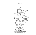
図1を参照して、本実施形態の二足歩行型ロボットRは、頭部1を上端部に支持する胴体2下部から一対の脚体3(図では便宜上、一本の脚体3のみを示す)が下方に延設され、また、胴体2上部の左右両側部から一対の腕体4(図では便宜上、一本の腕体4のみを示す)が延設されている。
【0025】
各脚体3は、その胴体2との連結箇所(股関節部分)と膝関節部分と足首関節部分とにそれぞれ股関節アクチュエータ5a、膝関節アクチュエータ5b及び足首関節アクチュエータ5cを備え、さらに、足首関節アクチュエータ5cの下側には、6軸力センサ6を介して脚体3の接地部分である足平部7が取着されている。この場合、本実施形態では、股関節アクチュエータ5aはロボットRの前後、左右及び上下方向の3軸回りの回転動作、膝関節アクチュエータ5bは、左右方向の1軸回りの回転動作、足首関節アクチュエータ5cは前後及び左右方向の2軸回りの回転動作を行うものであり、これらの各アクチュエータ5a〜5cを駆動することで、人間の脚とほぼ同様の脚体3の動作を行うことができるようになっている。尚、前記6軸力センサ6は、足平部7への作用力(ロボットRの前後、左右及び上下の3軸方向の力成分及びモーメント成分)を検出するものである。
【0026】
同様に、各腕体4は、胴体2との連結箇所(型関節部分)と肘関節部分と手首関節部分とにそれぞれ肩関節アクチュエータ8a、肘関節アクチュエータ8b及び手首関節アクチュエータ8cを備え、該手首関節アクチュエータ8cに6軸力センサ9を介してハンド10が取着されている。この場合、肩関節アクチュエータ8aは、ロボットRの前後、左右及び上下方向の3軸回りの回転動作、肘関節アクチュエータ8bは、ロボットRの左右方向の1軸回りの回転動作、手首関節アクチュエータ8cは前後、左右及び上下方向の3軸回りの回転動作を行うものである。
【0027】
また、胴体2には、前述の各アクチュエータ5a〜5c及び8a〜8cを駆動・制御する制御ユニット11や、ロボットRの上体姿勢を示す胴体2の傾斜状態を図示しない加速度センサやレートジャイロを用いて検出する傾斜検出器12が備えられている。さらに、各脚体3の各アクチュエータ5a〜5cの箇所にはそれらの変位(各軸回りの回転角)を検出するアクチュエータ変位検出器13a〜13cが備えられ、同様に、各腕体4の各アクチュエータ8a〜8cの箇所にもアクチュエータ変位検出器(図示を省略する)が備えられている。以下、各脚体3の各アクチュエータ5a〜5cを脚用アクチュエータ5と総称し、また、これらに対応する各アクチュエータ変位検出器13a〜13cをアクチュエータ変位検出器13と総称する。
【0028】
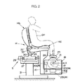
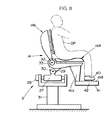
図2を参照して、ロボット操縦装置Sは、同図に仮想線で示すオペレータOPの上体を支持する上体支持機構として、オペレータOPが着座するシート14を備え、また、シート14に着座したオペレータOPがロボットRの脚体2を操縦するために該オペレータOPの両足平を載せる球体15を備えている。尚、ロボット操縦装置Sは、さらにロボットRの各腕体4を操縦するための装置も備えているのであるが、これについては、ここでは図示及び説明を省略する。
【0029】
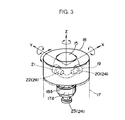
シート14の座部14aの前側下方には、球体15を支持するために座部14aにブラケット16を介して固設された球体支持用固定基台17が配置され、この固定基台17上に、球体15を保持する球体保持用回転基台18が図2のZ軸(上下方向の軸)回りに回転自在に設けられている。この回転基台18は、図3に示すようにその下面部の中心部から固定基台17の内部に向かって下方に突設された軸18aがベアリング17aを介して固定基台17に回転自在に支承され、これにより、固定基台17上で、Z軸回りに回転自在とされている。そして、球体15は、その下半部が回転基台18内に収容されて、該回転基台18と一体的にZ軸回りに左右方向に回転自在で、且つ図2及び図3のX軸(前後方向の軸)及びY軸(左右方向の軸)回りに回転自在なように回転基台17に保持されている。
【0030】
図3に示すように回転基台18の内部には、球体15の側面部(Y軸方向の面部)に外周面を圧接させて回転自在に設けられた回転ローラ19と、この回転ローラ19の回転量により球体15のX軸回りの回転量(回転角)を検出するロータリエンコーダ20と、球体15の後面部(X軸方向の面部)に外周面を圧接させて回転自在に設けられた回転ローラ21と、この回転ローラ21の回転量により球体15のY軸回りの回転量(回転角)を検出するロータリエンコーダ22とが備えられている。さらに、前記固定基台17の内部には、球体15のZ軸回りの回転量(回転角)を検出すべく、該球体15と一体的にZ軸回りに回転する回転基台18の軸18aの下端部に取り付けられたロータリエンコーダ23が備えられている。これらのロータリエンコーダ20,22,23は、本発明における球体回転検出手段24を構成するものである。
【0031】
また、本実施形態のシステムにおけるロボット操縦装置Sでは、シート14に着座したオペレータOPがその各足平に装着する一対のシューズ25(図では説明の便宜上、一つのシューズのみを示す)を備えており、オペレータOPはロボットRの操縦に際して該シューズ25を履いた上で、自身の足平を球体15の上面部(回転基台18から露出した部分)に載せるようになっている。この場合、各シューズ25の足底には、接点スイッチ等により構成された接地センサ26(足平接地/離反検出手段)が備えられており、該接地センサ26は、オペレータOPの足平の装着したシューズ25が球体15上に接地されているか球体15から離反されているかに応じてON/OFF信号を出力する。
【0032】
尚、シート14は、その座部14aが、前後方向の軸心27回りにアクチュエータ28により左右に傾動し(座部14aの左右の両側部が上下する)、さらに、左右方向の軸心29回りにアクチュエータ30により座部14aの前端部が上下する方向に傾動するように基台31上に支持されている。そして、シート14の背もたれ部14bは、左右方向の軸心32回りにアクチュエータ33により前後に傾動するように座部14aの後端部から起立され、この背もたれ部14bにオペレータOPの上体が図示しないバンド等により固定されるようになっている。このようなシート14の構造は、ロボットRの上体(胴体2)の傾斜姿勢を、オペレータOPが自身の上体の傾斜姿勢によりロボットRに指示したり、ロボットRの上体の姿勢の不安定さに応じて座部14aを傾動させたりするためのものであり、これについては、本願出願人が先に特願平8−343922号にて詳細に説明しているので、ここでは詳細な説明を省略する。
【0033】
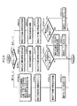
一方、本実施形態のシステムでは、前述のロボットRの動作制御を行うために、図4のブロック図に示す制御システムを備えている。
【0034】
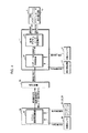
この制御システムは、その構成を大別すると、ロボット操縦装置S側に設けた制御ユニット34と、ロボットRに設けた前記制御ユニット11と、これらの制御ユニット34,11間での通信を行うための通信装置35とから構成されている。以下、制御ユニット34をマスター側制御ユニット34と称し、制御ユニット11をロボット側制御ユニット11と称する。尚、通信装置35の通信方式は有線及び無線のいずれの方式を使用してもよい。
【0035】
マスター側制御ユニット34は、ロボットRの脚体3の動作指令をロボット側制御ユニット11に与えるためにマスター演算処理装置36を備え、このマスター演算処理装置36に前記各シューズ25の接地センサ26の検知信号(シューズ25の球体15への接地や球体15からの離反を示すON/OFF信号)と、前記ロータリエンコーダ20,22,23による球体15の回転角の検出値とが与えられる。
【0036】
そして、このマスター演算処理装置36は、脚体動作指令手段を構成するものであり、各シューズ25の接地センサ26の検知信号に基づき、ロボットRの各脚体3の離床・着床を行わせるタイミングを規定する指令データ(以下、離床/着床指令という)を生成すると共に、ロータリエンコーダ20,22,23による球体15の回転角の検出値に基づき、ロボットRの遊脚側(離床側)の脚体3の足平部7の着床に際しての位置/姿勢を規定する指令データ(以下、着床足平位置/姿勢指令という)を生成し(詳細は後述する)、それらの指令データをロボットRの脚体動作指令として通信装置35を介してロボット側制御ユニット11に与える。
【0037】
尚、マスター側制御ユニット34には、前記マスター演算処理装置36の他、シート14の動作に関する制御装置等(図示しない)も備えており、シート14の背もたれ部14bの傾斜姿勢に応じてロボットRの上体を傾斜させるための上体姿勢指令(ロボットRの上体の傾斜角を規定する指令データ)をロボット側制御ユニット11に与えたりするのであるが、これについては前記特願平8−343922号にて本願出願人が詳細に説明しているので、ここでは詳細な説明を省略する。
【0038】
前記ロボット側制御ユニット11は、ロボットRの脚用アクチュエータ5の動作制御を行うために、ロボット脚主制御部37と脚用アクチュエータ変位制御部38とを備えている。
【0039】
ロボット脚主制御部37は、詳細は後述するが、マスター側制御ユニット34から与えられる前記脚体動作指令(離床/着床指令及び着床足平位置/姿勢指令)や、シート14の背もたれ部14bの傾斜に応じた上体姿勢指令、前記傾斜検出器12によるロボットRの上体(胴体2)の姿勢(傾斜)の検出値、前記6軸力センサ6により検出されるロボットRの足平部7への床からの作用力の検出値に基づいて、ロボットRの各脚用アクチュエータ5の目標変位を決定し、それを脚用アクチュエータ変位制御部38に指令する。
【0040】
脚用アクチュエータ変位制御部38は、ロボット脚主制御部37から指令された各脚用アクチュエータ5の目標変位と前記アクチュエータ変位検出器13により検出される各脚用アクチュエータ5の変位の検出値とに基づき、各脚用アクチュエータ5の変位を目標変位にフィードバック制御する。
【0041】
次に、本実施形態のシステムの作動を説明する。
【0042】
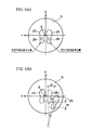
本実施形態のシステムでは、ロボットRを操縦するためにシート14に着座したオペレータOPがその各足平をこれに装着したシューズ25を介して球体15上に接地させる際には、例えば図5(a)に示すように球体15の上面部の中央付近(球体15の頂上付近)の所定の定位置に各シューズ25を前後方向に向けて載せる。この場合、右足平側のシューズ25を載せる定位置(以下、右足平接地基準位置という)は、球体15の上面部中央の右側の箇所で、左足平側のシューズ25を載せる定位置(以下、左足平接地基準位置という)は、球体15の上面部中央の左側の箇所である。
【0043】
そして、オペレータOPは、ロボットRをその脚体3の動作によって移動させようとする場合には、該オペレータOP自身が通常的に移動する場合と同様にして、一方の脚側(遊脚側)の足平を持ち上げてその足平のシューズ25を球体15から一旦離反させ、さらに、その足平を球体15上に向かって降ろして該足平のシューズ25を球体15上の接地基準位置に前後方向に向けて接地させる(遊脚側の足平の離床・着床動作を行う)。また、オペレータOPの他方の脚側(支持脚側)の足平については、遊脚側の足平のシューズ25を球体15の接地基準位置に接地させる際における遊脚側の足平と支持脚側の足平との相対的な位置関係や姿勢関係(向き関係)が、ロボットRに行わせようとする移動形態でオペレータOP自身が実際に移動する場合における遊脚側の足平の着床時の両足平の相対的な位置関係や姿勢関係と同じような関係になるように、球体15にシューズ25を介して接地させている足平を、その接地状態を維持したまま動かして、その動きにより該球体15を回転させる。
【0044】
具体的には、例えばロボットRを前進側に歩行させるに際してロボットRの左側の脚体3を前進側に一歩、踏み出させようとする場合には、オペレータOPは、その左足平を球体15上から持ち上げて、該左足平を球体15上の左足平接地基準位置に前後方向に向けて降ろし、この際、該左足平を球体15から離反させている間に、右足平のシューズ25を球体15に接地させたまま、該右足平を例えば図5(b)に示すような位置に手前側(シート14の近づく側)に動かして、球体15を回転させる。すなわち、オペレータOP自身が実際に前進歩行する場合に、その支持脚側の足平が遊脚側の足平に対して後方に移動するのと同じようにして、球体15上にシューズ25を介して接地させている足平を動かして球体15を回転させる。この場合、球体15上に接地させている足平の前記接地基準位置からの移動量は、ロボットRに行わせようとする移動形態(歩行形態)での歩幅に対応させ、その歩幅が大きい程、球体15上に接地させている足平の移動量を大きくする(球体15の回転量を大きくする)。
【0045】
また、例えばロボットRを前進側に歩行させるに際して、ロボットRの遊脚側の脚体3の足平部7を支持脚側の脚体3の足平部7に対して斜め向きに着床させ、ロボットRの移動方向を変更させるような場合には、オペレータOPは、ロボットRの遊脚側の脚体3の足平部7の着床時の両足平部7の相対的な姿勢関係(向き関係)と合わせるようにして、球体15上にシューズ25を介して接地させているオペレータOPの足平を動かして球体15を回転させる。例えばロボットRの左側の脚体3を遊脚側として該脚体3の足平部7を右側の脚体3(支持脚側の脚体3)の足平部7の向きに対して左斜め向きに着床させようとする場合には、その着床時における右側の脚体3の足平部7の向きは、左側の脚体3の足平部7の向きに対して右斜め向きとなるので、オペレータOPは、図5(b)に示すように該オペレータOPの左足平のシューズ25を球体15上の左足平接地基準位置に前後方向に向けて接地させる際に、右足平のシューズ25が右斜めに向くように球体15を該足平の動きにより回転させる(この回転は球体15のZ軸回りの回転によりなされる)。
【0046】
尚、前述のようなオペレータOPの足平の動かし方は、ロボットRを後進側に移動させるような場合についても同様である。また、ロボットRに足踏みをさせるような場合には、オペレータOPはその両足平を前記球体15の接地基準位置に対して交互に上下させればよい。
【0047】
このようにして、オペレータOPがロボットRに行わせようとする形態で該オペレータOPの各足平を動かしつつ球体15を回転させている際に、オペレータOPの各足平の球体15上への接地及び該球体15からの離反が、各足平のシューズ25の前記接地センサ26によって各足平毎に検知され、それが前記マスター側制御ユニット34のマスター演算処理装置36に与えられる。
【0048】
このとき、マスター演算処理装置36は、球体15からの離反が接地センサ26により検知されたオペレータOPの足平に対応する側のロボットRの脚体3を離床させるべき脚体3として決定して、該オペレータOPの足平の球体15からの離反の検知及びその後の球体15上への接地の検知に応じて該足平に対応するロボットRの脚体3の前記離床/着床指令を生成し、それを前記通信装置35を介してロボット側制御ユニット11に送信する。
【0049】
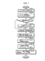
また、このとき、マスター演算処理装置36は、図6のフローチャートに示す演算処理を所定の制御サイクルで行う。
【0050】
すなわち、マスター演算処理装置36は、まず、オペレータOPの足平の動作モードを判別する(STEP6−1)。ここで、動作モードは接地モードと空中モードと降下モードとがあり、接地モードは、オペレータOPがその両足平をシューズ25を介して球体15上に継続的に接地させている状態を示すモード、空中モードは、オペレータOPがその一方の足平を持ち上げて該足平のシューズ25を球体15から離反させた状態を示すモード、降下モードは、オペレータOPが、持ち上げた足平のシューズ25を球体15上に接地させた際の状態を示すモードである。この場合、ロボットRの操縦の開始時には、オペレータOPはその両足平のシューズ25を前記図5(a)に示したように球体15上に接地させておくので、該動作モードの初期モードは接地モードである。
【0051】
そして、上記の判別で動作モードが接地モードである場合には、マスター演算処理装置36は、前記着床足平位置/姿勢指令を現状のままに保持し(STEP6−2)、前記各ロータリエンコーダ20,22,23により検出される前記X,Y,Zの各軸回りの球体15の回転角(回転量)を積算する(STEP6−3)。
【0052】
ここで、オペレータOPの両足平が球体15上に接地されている接地モードで球体15の回転角を積算するのは次のような理由による。すなわち、本実施形態では、オペレータOPがその各足平を球体15上に接地させる際には、図5(a)に示した接地基準位置で前後方向に向けて各足平を球体15上に接地させることを基本とし、その接地基準位置からの接地側の足平(ロボットRの支持脚側の脚体3に対応する足平)の移動量及び移動方向に応じて、ロボットRの遊脚側の脚体3の足平部7の支持脚側の足平部7に対する着床位置や姿勢(向き)をロボットRに指令する(前記着床足平位置/姿勢指令)。このため、オペレータOPがその両足平のシューズ25を球体15上に接地させている際に、オペレータOPが不用意にその両足平を動かして球体15を回転させてしまうと、その後に一方の足平を持ち上げて、他方の接地側の足平により球体15を前述の如く回転させた場合に、該一方の足平を持ち上げてから該足平を球体15上の接地基準位置に接地させるまでの球体15の接地側の足平による回転角を把握しただけでは、その回転角から、前記のような接地基準位置からの接地側の足平の移動量及び移動方向を正しく把握することができない。このために、本実施形態では、前記STEP6−3において、接地モードにおける球体15のX,Y,Zの各軸回りの回転角を積算しておく。
【0053】
尚、オペレータOP自身が一方の足平を球体15から離反させる際の他方の足平の位置や向きを認識しておき、それによって、該オペレータOP自身が球体15上に接地させている足平の移動量や移動方向を調整するような場合には、前記STEP6−3の処理を省略するようにしてもよい。
【0054】
次いで、マスター演算処理装置36は、前記STEP6−2で保持した着床足平位置/姿勢指令を通信装置35を介してロボット側制御ユニット11に送信した後(STEP6−4)、前記シューズ25の接地センサ26の検知信号によって、オペレータOPのいずれか一方の足平のシューズ25が球体15から離反されたかを判断する(STEP6−5)。そして、この判断で、オペレータOPの両足平のシューズ25が球体15上に接地している場合(STEP6−5でNO)には、接地モードに対応する今回の制御サイクルの処理を終了する。また、STEP6−5の判断結果がYESである場合には、球体15から離反されたオペレータOPの足平が左右いずれの足平であるかを示す左右判定結果(これは左右いずれの側のシューズ25の接地センサ26によって足平の球体15からの離反が検知されたかによって認識される)を図示しないメモリに記憶し(STEP6−6)、さらに動作モードを空中モードに変更した後(STEP6−7)、今回の制御サイクルの処理を終了する。
【0055】
次に、前記STEP6−1の判別結果が空中モードである場合(これは前記接地モードでSTEP6−7の処理が行われた後の次の制御サイクルで生じる)には、マスター演算処理装置36は、前記着床足平位置/姿勢指令を現状のままに保持し(STEP6−8)、前記各ロータリエンコーダ20,22,23により検出される前記X,Y,Zの各軸回りの球体15の回転角(回転量)を積算する(STEP6−9)。この積算は、前記接地モードから継続的に行われる。
【0056】
そして、マスター演算処理装置36は、STEP6−8で保持した着床足平位置/姿勢指令を通信装置35を介してロボット側制御ユニット11に送信した後(STEP6−10)、オペレータOPの各足平のシューズ25の接地センサ26の検知信号によって、オペレータOPの両足平のシューズ25が球体15上に接地されたか否かを判断する(STEP6−11)。この判断結果がNOである場合、すなわち、オペレータOPの持ち上げた一方の足平がまだ球体15上に降ろされていない場合には、今回の制御サイクルの処理を終了し、また、上記判断結果がYESである場合、すなわち、オペレータOPが持ち上げた一方の足平のシューズ25を球体15上に接地させた場合には、動作モードを降下モードに変更した後(STEP6−12)、今回の制御サイクルの処理を終了する。
【0057】
次に、前記STEP6−1の判別結果が降下モードである場合(これは前記空中モードでSTEP6−12の処理が行われた後の次の制御サイクルで生じる)には、マスター演算処理装置36は、前記接地モードから空中モードにかけて前記STEP6−3及び6−9で求められた球体15の各軸回りの回転角の積算値と、前記STEP6−6で記憶された左右判定結果とを基に、ロボットRの遊脚側の脚体3の足平部7の支持脚側の脚体3の足平部7に対する着床足平位置/姿勢指令を決定する(STEP6−13)。
【0058】
さらに詳細には、例えば図5(b)に示したように球体15が回転された場合(オペレータOPが左足平を持ち上げて右足平により球体15を手前側に回転させた場合)において、前記STEP6−6で記憶される左右判定結果は左であり(接地モードでオペレータOPの左足平が球体15から離反される)、このときマスター演算処理装置36は、前記X軸及びY軸回りの球体15の回転角の積算値から所定の演算式によって、オペレータOPの右足平の前記右足平接地基準位置からのX軸方向(前後方向)の移動量Δx(図5(b)ではΔx<0)及びY軸方向(左右方向)の移動量Δy(図5(b)ではΔy<0)を算出する。また、マスター演算処理装置36は、Z軸回りの球体15の回転角の積算値をオペレータOPの右足平の前記右足平接地基準位置からのZ軸回り(鉛直軸回り)の回転角Δθ(図5(b)ではΔθ<0)として得る。
そして、マスター演算処理装置36は、上記移動量Δx,Δy及び回転角Δθから、ロボットRの遊脚側の脚体3(図5(b)の場合、左側の脚体3)の足平部7の支持脚側の脚体3(図5(b)の場合、右側の脚体3)の足平部7に対する着床足平位置/姿勢指令を次のように決定する。すなわち、ロボットRの遊脚側の脚体3の足平部7の前後方向(X軸方向)における着床位置を、前記X軸方向の移動量Δxに所定の負のゲイン定数(−k1 )を乗算した値−k1 ・Δxだけ、遊脚側の足平部7の前後方向で支持脚側の脚体3の足平部7に対して前方に移動させた位置として決定する。また、ロボットRの遊脚側の脚体3の足平部7の左右方向(Y軸方向)における着床位置を、前記Y軸方向の移動量Δyに所定の負のゲイン定数(−k2 )を乗算した値−k2 ・Δyに所定のオフセット値aを加算してなる値(−k2 ・Δy+a)だけ、遊脚側の足平部7の左右方向で支持脚側の脚体3の足平部7に対して左方に移動させた位置として決定する。ここで、上記オフセット値aは、Δy=0のとき(例えばロボットRの直進歩行時)におけるロボットRの両足平部7,7の左右方向の間隔を規定するものである。また、ロボットRの遊脚側の脚体3の足平部7の着床姿勢を、前記Z軸回りの回転角Δθに所定の負のゲイン定数(−k3 )を乗算した値−k3 ・Δθだけ、支持脚側の脚体3の足平部7の向きに対して鉛直軸回りに左方向に回転させた向きとして決定する。
【0059】
尚、上記のような着床足平位置/姿勢指令の決定は、オペレータOPが右足平を持ち上げて、左足平により球体15を回転させた場合にも同様に行われる。この場合には、ロボットRの左側の脚体3の足平部7に対する右側の脚体3の足平部7の着床足平位置/姿勢指令が決定される。
【0060】
このようにしてロボットRの着床足平位置/姿勢指令を決定することで、該着床足平位置/姿勢指令は、オペレータOPが持ち上げた一方の足平を球体15の接地基準位置に接地させた際の両足平の相対的な位置/姿勢関係に対応したものに決定される。
【0061】
尚、本実施形態では、ロボットRの遊脚側の脚体3の足平部7の着床/位置姿勢指令を遊脚側の足平部7を基準とした座標系で決定してしているが、該着床/位置姿勢指令をロボットRの支持脚側の足平部7を基準とした座標系に変換した上で、ロボットRに与えるようにしてもよい。
【0062】
図6に戻って、マスター演算処理装置36は、次に、球体15の各軸回りの回転角の積算値をクリア(積算値を「0」にリセットする)した後(STEP6−14)、前記STEP6−13で決定した着床足平位置/姿勢指令を通信装置35を介してロボット側制御ユニット11に送信し(STEP6−15)、さらに、動作モードを接地モードに変更した後(STEP6−16)、今回の制御サイクルの処理を終了する。
【0063】
一方、前述のようなロボット操縦装置S側での動作や制御処理が行われたとき、ロボット側制御ユニット11のロボット脚主制御部37は、所定の制御サイクルで図7のフローチャートに示す処理を行う。
【0064】
すなわち、ロボット脚主制御部37は、ロボットRに備えられた前記傾斜検出器12や6軸力センサ6等のセンサの出力を読み込み(STEP7−1)、さらにマスター側制御ユニット34から通信装置35を介して与えられる前述の脚体動作指令(離床/着床指令及び着床足平位置/姿勢指令)や、シート14の背もたれ部14bの傾動に基づく上体姿勢指令を受信する(STEP7−2)。
【0065】
次いで、ロボット脚主制御部37は、前記離床/着床指令によって、いずれか一方の脚体3についての着床要求が有るか否かを判断し(STEP7−3)、着床要求が有る場合には、ロボットRの脚体3の足運びの形態やロボットRの上体の姿勢を規定する基本の目標歩容を前記着床足平位置/姿勢指令や上体姿勢指令に従って生成する(STEP7−4)。ここで、目標歩容は、ロボットRの上体(胴体2)の目標姿勢(上体の目標傾斜角)や、遊脚側の脚体3の着床の際の目標足平位置/姿勢、ロボットRの歩行に際して支持脚側の脚体3の足平部7が床から受ける床反力の中心の目標軌道等の特徴を記述するパラメータにより構成され、これらのパラメータを前記着床要求を受けた脚体3についての一歩分について生成する。この場合、足平部7が受ける床反力中心の目標軌道は、足平部7の接地面、あるいは両足平部7の接地面を含む最小面積の多角形(これは一般に支持多角形と言われる)内に存するように生成する。また、該目標歩容における遊脚側の脚体3の着床の際の目標足平位置/姿勢は、前記着床足平位置/姿勢指令に従って生成する。
【0066】
尚、このような目標歩容の生成は、本願出願人が例えば特開平5−318340号公報に詳細に開示しているので、ここでは、さらなる説明を省略する。
【0067】
次いで、ロボット脚主制御部37は、前述の如く生成された基本の目標歩容から、現在の制御サイクルにおける目標歩容の瞬時値を算出した後(STEP7−5)、さらに、ロボットRの姿勢が転倒しやすい不安定な姿勢となるのを排除するために、該ロボットRの姿勢を安定化する制御を行って、STEP7−5で算出された目標歩容の瞬時値を修正する(STEP7−6)。
【0068】
この姿勢安定化制御では、ロボット脚主制御部37は、所謂コンプライアンス制御によって、予期せぬ床の凹凸や傾斜により足平部7が受ける床反力の影響を該足平部7により吸収するように前記6軸力センサ6の検出値に応じて基本の目標歩容における目標足平位置/姿勢を修正し、また、ロボットRの上体姿勢の復元方向に足平部7に床反力が作用するように基本の目標歩容におけるロボットRの上体の目標姿勢と前記傾斜検出器12の検出値との偏差に応じて該目標足平位置/姿勢を修正する。さらに、ロボットRの上体姿勢の復元方向にロボットRの上体の慣性力が生じるように、基本の目標歩容におけるロボットRの上体の目標姿勢と前記傾斜検出器12の検出値との偏差に応じてロボットRの上体の姿勢や位置を修正する。
【0069】
尚、このような姿勢安定化制御は本願出願人が例えば特開平5−337849号公報に詳細に開示しているので、ここでは、さらなる説明を省略する。
【0070】
次いで、ロボット脚主制御部37は、上記のように修正した目標歩容の瞬時値からそれに対応した今回の制御サイクルにおける各脚体3の各脚用アクチュエータ5の目標変位を算出し(STEP7−7)、それを脚用アクチュエータ変位制御部38に指令する(STEP7−8)。このとき、脚用アクチュエータ変位制御部38は指令された目標変位に従って各脚用アクチュエータ5の変位を該目標変位にフィードバック制御する。
【0071】
そして、この後、ロボット脚主制御部37は、ロボット操縦装置Sのシート14の座部14aの傾動のため等に必要なロボットRの動作情報を通信装置35を介してマスター側制御ユニット34に送信して(STEP7−9)、今回の制御サイクルの処理を終了する。
【0072】
以上のようなロボットR側での作動によって、ロボットRは自己の姿勢の安定化を自律的に図りつつ、基本的には、オペレータOPの足平の動作と同じような形態で脚体3を動かす。尚、この時のロボットRの脚体3の動作はオペレータOPの足平の動きに対して一歩分遅れて行われる。
【0073】
このようなロボットRの遠隔制御システムによれば、オペレータOPがその足平を球体15に対して上下させる際における該オペレータOPの遊脚側の足平に対する支持脚側の足平(球体15に接地させている足平)の移動量や移動方向によって、ロボットRの移動時の歩幅や移動方向が規定されるため、オペレータOPは自身の足平の動きを、ロボットRの脚体3の動きとして感覚的に認識することができ、確実にロボットRの脚体3の所望の動作を行わしめることができる。また、オペレータOPは、シート14に着座したまま足平を動かすことで、ロボットRを移動させることができるので、ロボット操縦装置S側に広範な設備を設けずとも、ロボットRを広い範囲で移動させることができる。
【0074】
尚、本実施形態では、ロボットRの着床足平位置/姿勢指令を決定するための球体15の回転角をロータリエンコーダ20,22,23を用いて検出するようにしたが、例えば非接触の速度センサを用いて球体15の各軸回りの回転速度を検出し、それを積分することで球体15の回転角を求めるようにしてもよい。
【0075】
また、本実施形態では、オペレータOPの球体15上への接地や球体15からの離反をシューズ25に設けた接地センサ26により検出するようにしたが、荷重センサや光学的なセンサあるいは電磁的なセンサを用いてオペレータOPの足平の接地や離反を検出するようにしてもよい。
【0076】
また、本実施形態において、ロボット側制御ユニット11からマスター側制御ユニット34にロボットRの脚体3の動作情報を送信するようにし、それに応じて、ロボットRの脚体3の過剰な動き等を防止するために、球体15の回転や着床足平位置/姿勢指令の決定値を制限するようにしてもよい。尚、球体15の回転量を制限するためには、例えばロータリエンコーダ20,22,23と同軸にアクチュエータ(モータ)やブレーキ装置を備えればよい。
【0077】
次に、本発明の第2実施形態の遠隔制御システムを図8乃至図11を参照して説明する。尚、本実施形態のシステムでは、ロボットの構成(ロボット側制御ユニットを含む)は前記第1実施形態のものと同一で、ロボット操縦装置やマスター側制御ユニットの一部のみが第1実施形態と相違しているので、同一構成部分については、第1実施形態と同じ図面及び参照符号を用いて説明する。
【0078】
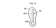
図8は、前記図1に示したロボットRを操縦するための本実施形態のロボット操縦装置S’を示すものであり、この操縦装置S’では、前記第1実施形態のものと同一構造のシート14の前側下方に、シート14に着座したオペレータOPがその両足平をそのそれぞれに装着したシューズ40を介して載せる平板状の足平載架体41を備え、該足平載架体41がブラケット41xを介してシート14の座部14aに固設されている。この場合、各シューズ40の足底には、例えば図9に示すような形状の突起52が設けられており、この突起42は、足底の踵部分に存する円形部42aと、足底の長手方向に延在する長尺部42bとにより構成されている。尚、シューズ40の突起42は足平載架体41上を滑らせることができるような部材(足平載架体41の上面部との間の摩擦係数が小さな部材)により形成されている。また、円形部42aの形状は円形に限らず、例えば四角形や三角形であってもよい。
【0079】
前記足平載架体41の上面部は、例えば接触の有無を検出する小さな接触センサ(図示しない)をマトリクス状に配列してなる分布型接触センサ41aにより構成され、該分布型接触センサ41aは、これに何らかの物が接触したとき、その接触面の位置や形状を示すデータを出力する。
【0080】
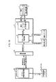
また、図10を参照して、本実施形態でロボットRの動作制御を行うための制御システムは、前記第1実施形態と同様にロボット側制御ユニット11、マスター側制御ユニット34及び通信装置35により構成され、マスター側制御ユニット34には、前記分布型接触センサ41aの検出データを与えるマスター演算処理装置43が備えられている。
【0081】
このマスター演算処理装置43は、前記分布型接触センサ41aと併せて足平接地/離反検出手段44としての機能を有し、オペレータOPの各足平に装着したシューズ40の突起42に対応する接触面が分布型接触センサ41aにより検出されるか否かでオペレータOPの各足平の足平載架体41上への接地及び該足平載架体41からの離反を認識する。例えば、足平載架体41上の二カ所に突起42との接触面が分布型接触センサ41aにより検出される場合には、両足平の足平載架体41上への接地状態が認識され、この状態から例えば右側の突起42との接触面が検出されなくなった場合には、オペレータOPの右足平の足平載架体41からの離反が認識される。尚、オペレータOPの各足平の足平載架体41に対する接地・離反の検出に際しての左右の区別は、例えば突起42の形状あるいは大きさを左右で異なるものとして、それらの突起42と足平載架体41との接触面の相違に基づいて行うようにしてもよい。
【0082】
また、マスター演算処理装置43は、前記分布型接触センサ41aと併せて、オペレータOPの両足平の足平載架体41上への接地時における両足平の相対的な位置/姿勢を検出する足平位置/姿勢検出手段45としての機能を有し、分布型接触センサ41aの出力データから足平載架体41上での各足平の突起42の円形部42aの位置(足平載架体41に固定された平面座標系での位置)を認識し、その認識した各突起42の円形部42aの位置から、足平載架体41上における一方の足平側の前記突起42の円形部42aに対する他方の足平側の前記突起42の円形部42aの位置を両足平の相対的な位置として認識する。さらに、マスタ演算処理装置43の足平位置/姿勢検出手段45としての機能は、分布型接触センサ41aの出力データから足平載架体41上での各足平の突起42の長尺部42bの向きを認識し、その認識した各突起42の長尺部42bの向きから、足平載架体41上における一方の足平側の前記突起42の長尺部42bの向きに対する他方の足平側の前記突起42の長尺部42bの向きを両足平の相対的な姿勢として認識する。
【0083】
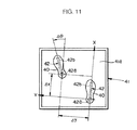
より具体的には、例えば図11に示すように両足平のシューズ40の突起42が足平載架体41上に接地された場合において、マスター演算処理装置43の足平位置/姿勢検出手段45としての機能は、例えば右足平側の突起42の円形部42aに対する左足平側の突起42の円形部42bの、右足平側の突起42の長尺部42bの長手方向(図11のX軸方向)及びこれと直交する方向(図11のY軸方向)における変位両Δx,Δyを両足平の相対的位置を示すものとして認識し、また、右足平側の突起42の長尺部42bの方向(X軸方向)に対する左足平側の突起42の長尺部42bの方位角Δθを両足平の相対的姿勢を示すものとして認識する。
【0084】
また、マスター演算処理装置43は、脚体動作指令手段46としての機能も有し、この機能では、前述のように足平接地/離反検出手段44により把握されるオペレータOPの各足平の足平載架体41に対する接地・離反や、足平位置/姿勢検出手段45により把握されるオペレータOPの両足平の相対的な位置/姿勢に基づき、前記第1実施形態で説明した前記離床/着床指令及び着床足平位置/姿勢指令を決定し(詳細は後述する)、これらの指令を脚体動作指令として通信装置35を介してロボット側制御ユニット11に送信する。
【0085】
以上説明した以外の他の構成は、前記第1の実施形態と同一である。
【0086】
次に、本実施形態のシステムの作動を説明する。
【0087】
本実施形態のシステムでは、オペレータOPは、ロボットRをその脚体3の動作によって移動させようとする場合には、該オペレータOP自身が通常的に移動する場合と同様にして、両足平を足平載架体41上に載せた状態から、遊脚側の足平を持ち上げてその足平のシューズ40を足平載架体41から一旦離反させ、さらに、該遊脚側の足平をロボットRの遊脚側の脚体3の足平部7を動かそうとする方向に向かって移動させつつ、支持脚側の足平を、これに装着したシューズ40を介して足平載架体41上に接触させたまま該足平載架体41上を滑らせるようにして、遊脚側の足平と逆向きに移動させる。そして、最終的に、持ち上げた足平を足平載架体41上に降ろし、この際、オペレータOPの両足平の相対的な位置/姿勢関係が、ロボットRに行わせようとする脚体3の動作形態での遊脚側の脚体3の着床時の両足平部7の相対的な位置/姿勢関係と同じような関係になるように、オペレータOPの両足平を動かす。
【0088】
例えばロボットRを前進側に歩行させるに際してロボットRの左側の脚体3を前進側に一歩、踏み出させようとする場合には、オペレータOPは、その左足平を足平載架体41上から持ち上げて前方側に移動させると同時に、右足平のシューズ40を足平載架体41上に接地させたまま後方(シート14に近づく方向)に足平載架体41上を摺動させる。そして、図11に示すように、左足平を足平載架体41上に降ろすに際して、該左足平の接地時の両足平の前後方向の間隔が、ロボットRに行わせようとする歩行形態での該ロボットRの歩幅に対応する間隔となるような両足平の位置関係で左足平を足平載架体41上に降ろす。
【0089】
また、例えばロボットRを前進側に歩行させるに際して、ロボットRの遊脚側の脚体3の足平部7を支持脚側の脚体3の足平部7に対して斜め向きに着床させ、ロボットRの移動方向を変更させるような場合には、オペレータOPは、ロボットRの遊脚側の脚体3の足平部7の着床時の両足平部7の相対的な姿勢関係(向き関係)と合わせるようにして、両足平を動かす。例えばロボットRの左側の脚体3を遊脚側として該脚体3の足平部7を右側の脚体3(支持脚側の脚体3)の足平部7の向きに対して左斜め向きに着床させようとする場合には、オペレータOPは、図11に示すように、該オペレータOPの左足平のシューズ40を足平載架体41上に接地させる際に、右足平のシューズ40の向き(突起42の長尺部42bの向き)に対して左足平のシューズ40の向きが左斜めに向くように両足平を動かす。
【0090】
尚、前述のようなオペレータOPの足平の動かし方は、ロボットRを後進側に移動させるような場合についても同様である。また、ロボットRに足踏みさせるような場合には、オペレータOPはその両足平を足平載架体41上の同じ場所で上下させればよい。
【0091】
このようにして、オペレータOPがロボットRに行わせようとする形態で該オペレータOPの各足平を動かしている際に、オペレータOPの各足平の足平載架体41に対する接地・離反が、前記マスター演算処理装置43の足平接地/離反検出手段44としての機能によって、前述の如く分布型接触センサ41aの出力データに基づいて把握される。
【0092】
このとき、マスター演算処理装置43は、足平載架体41からの離反が把握されたオペレータOPの足平に対応する側のロボットRの脚体3を離床させるべき脚体3として決定して、該オペレータOPの足平の足平載架体41からの離反及びその後の足平載架体41上への接地に応じて該足平に対応するロボットRの脚体3の前記離床/着床指令を生成し、それを前記通信装置35を介してロボット側制御ユニット11に送信する。
【0093】
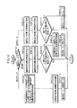
また、このとき、マスター演算処理装置43は、図12のフローチャートに示す演算処理を所定の制御サイクルで行う。
【0094】
すなわち、マスター演算処理装置43は、まず、前記第1実施形態と同様、オペレータOPの足平の動作モード(接地モード、空中モード及び降下モードの3種類)を判別する(STEP12−1)。この場合、ロボットRの操縦開始時の初期モードは接地モードである。
【0095】
そして、上記の判別で動作モードが接地モードである場合(オペレータOPの両足平のシューズ40が足平載架体41上に接地されている場合)には、マスター演算処理装置43は、前記着床足平位置/姿勢指令を現状のままに保持し(STEP12−2)、その保持した着床足平位置/姿勢指令を通信装置35を介してロボット側制御ユニット11に送信する(STEP12−3)。
【0096】
次いで、マスター演算処理装置43は、その足平接地/離反検出手段44としての機能によるオペレータOPの各足平の足平載架体41に対する接地・離反の把握に基づいて、オペレータOPのいずれか一方の足平のシューズ40が足平載架体41から離反されたかを判断する(STEP12−4)。そして、この判断で、オペレータOPの両足平のシューズ40が足平載架体41上に接地している場合(STEP12−4でNO)には、今回の制御サイクルの処理を終了する。また、上記の判断結果がYESである場合には、足平載架体41から離反されたオペレータOPの足平が左右のいすれの足平であるかを示す左右判定結果(これは足平接地/離反検出手段44により把握される)を図示しないメモリに記憶し(STEP12−5)、さらに、動作モードを空中モードに変更した後(STEP12−6)、今回の制御サイクルの処理を終了する。
【0097】
次に、前記STEP12−1の判別結果が空中モードである場合(これは前記STEP12−6の処理が行われた後の次の制御サイクルで生じる)には、マスター演算処理装置43は、前記着床足平位置/姿勢指令を現状のままに保持し(STEP12−7)、その保持した着床足平位置/姿勢指令を通信装置35を介してロボット側制御ユニット11に送信する(STEP12−8)。さらに、マスター演算処理装置43は、足平接地/離反検出手段44としての機能によるオペレータOPの各足平の足平載架体41に対する接地・離反の把握に基づいて、オペレータOPの両足平のシューズ40が足平載架体41上に接地されたか否かを判断する(STEP12−9)。この判断結果がNOである場合、すなわち、オペレータOPの持ち上げた一方の足平がその持ち上げ状態のままである場合には、今回の制御サイクルの処理を終了する。また、上記判断結果がYESである場合、すなわちオペレータOPが持ち上げた一方の足平のシューズ40を足平載架体41上に接地させた場合には、動作モードを降下モードに変更した後(STEP12−10)、今回の制御サイクルの処理を終了する。
【0098】
次に、前記STEP12−1の判別結果が降下モードである場合(これは前記STEP12−10の処理が行われた後の制御サイクルで生じる)には、マスター演算処理装置43は、前記分布型接触センサ41aの検出データと前記STEP12−5で記憶された左右判定結果とを基に、ロボットRの遊脚側の脚体3の足平部7の支持脚側の脚体3の足平部7に対する着床足平位置/姿勢指令を決定する(STEP12−11)。
【0099】
さらに詳細には、例えばオペレータOPがその左足平を持ち上げて、該左足平を前方側に動かすと共に足平載架体41上に接地させている右足平を後方側に動かし、最終的に前記図11に示したような両足平のシューズ40の位置/姿勢関係で左足平のシューズ40を足平載架体41上に接地させた場合において、前記STEP12−5で記憶される左右判定結果は左である(接地モードでオペレータOPの左足平のシューズ40が足平載架体41から離反される)。このとき、マスター演算処理装置43は、その足平位置/姿勢検出手段45としての機能によって、現在の右足平のシューズ40の突起42を基準として、その右足平側の突起42の円形部42aに対する左足平側の突起42の円形部42aの、右足平側の突起42の長尺部42bの長手方向(図11のX軸方向)及びこれと直交する方向(図11のY軸方向)における変位量Δx,Δyと、右足平側の突起42の長尺部42bの方向(X軸方向)に対する左足平側の突起42の長尺部42bの方位角Δθとを分布型接触センサ41aの出力データから算出する。
【0100】
そして、マスター演算処理装置43は、その脚体動作指令手段46によって、上記変位量Δx,Δy及び方位角Δθから、ロボットRの遊脚側の脚体3(図11の場合、左側の脚体3)の足平部7の支持脚側の脚体3(図11の場合、右側の脚体3)の足平部7に対する着床足平位置/姿勢指令を次のように決定する。すなわち、ロボットRの遊脚側の脚体3の足平部7の前後方向(X軸方向)における着床位置を、前記変位量Δxに所定の正のゲイン定数kaを乗算してなる値ka・Δxだけ、支持脚側の脚体3の足平部7に対して前方向に移動させた位置として決定する。また、ロボットRの遊脚側の脚体3の足平部7の左右方向(Y軸方向)における着床位置を、前記変位量Δyに所定の正のゲイン定数kbを乗算してなる値kb・Δyに所定のオフセット値aを加算してなる値(kb・Δy+a)だけ、支持脚側の脚体3の足平部7に対して左方向に移動させた位置として決定する。ここで、上記オフセット値aは、Δy=0のとき(例えばロボットRの直進歩行時)におけるロボットRの脚体3の足平部7,7の左右方向の間隔を規定するものである。また、ロボットRの遊脚側の脚体3の足平部7の着床姿勢を、前記方位角Δθに所定の正のゲイン係数kcを乗算してなる値kc・Δθだけ、支持脚側の脚体3の足平部7の向きに対して鉛直軸回りに左方向に回転させた向きとして決定する。
【0101】
尚、上記のような着床足平位置/姿勢指令の決定は、オペレータOPが右足平を持ち上げて、両足平を移動させた場合にも同様に行われる。この場合には、ロボットRの左側の脚体3の足平部7に対する右側の脚体3の足平部7の着床足平位置/姿勢指令が決定される。
【0102】
このようにしてロボットRの着床足平位置/姿勢指令を決定することで、該着床足平位置/姿勢指令は、オペレータOPが持ち上げた一方の足平を足平載架体41上に接地された際の両足平の相対的な位置/姿勢関係に対応したものに決定される。
【0103】
図12に戻って、マスター演算処理装置43は、次に、前記STEP12−11で決定した着床足平位置/姿勢指令を通信装置35を介してロボット側制御ユニット11に送信し(STEP12−12)、さらに、動作モードを接地モードに変更した後(STEP12−13)、今回の制御サイクルの処理を終了する。
【0104】
尚、マスター演算処理装置43から前述の如く離床/着床指令や着床足平位置/姿勢指令が与えられるロボット側制御ユニット11の処理は、前記第1実施形態と全く同一で(図7参照)、この処理によって、ロボットRは自己の姿勢の安定化を自律的に図りつつ、基本的には、オペレータOPの足平の動作と同じような形態で脚体3を動かす。この時のロボットRの脚体3の動作はオペレータOPの足平の動きに対して一歩分遅れて行われる。
【0105】
このようなロボットRの遠隔制御システムによれば、オペレータOPがシート14に着座したまま歩行するかのようにして、その足平を足平載架体41に対して上下させながら動かすことで、持ち上げ側の足平の足平載架体41上への接地時における両足平の相対的な位置/姿勢によってロボットRの移動時の歩幅や移動方向が規定されるため、前記第1実施形態と同様に、オペレータOPは自身の足平の動きを、ロボットRの脚体3の動きとして感覚的に認識することができ、確実にロボットRの脚体3の所望の動作を行わしめることができる。また、オペレータOPは、シート14に着座したまま足平を動かすことで、ロボットRを移動させることができるので、ロボット操縦装置S’側に広範な設備を設けずとも、ロボットRを広い範囲で移動させることができる。
【0106】
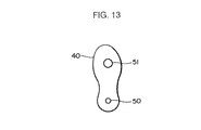
尚、本実施形態では、足平載架体41上の両足平の相対的な位置/姿勢を検出するために、各足平に装着するシューズ40に設けた前述の形状の突起42を用いたが、例えば図13に示すように、二つの突起50,51を各シューズ40の足底に該シューズ40の長手方向に間隔を存して設けておき、これらの突起50,51のうち、例えば突起50の相対的な位置によって、両足平の相対的な位置を把握すると共に、各シューズ40毎に突起50に対する突起51の位置によって各シューズ40を装着した各足平の向きを把握して、それによって、両足平の相対的な姿勢(向き)を認識するようにしてもよい。さらには、各足平と足平載架体との接触面の形状からパターン認識的な手法によって、両足平の相対的な位置や姿勢関係を把握するようにしてもよい。
【0107】
また、本実施形態では、オペレータOPの足平の足平載架体41に対する接地・離反や、両足平の接地時の相対的な位置/姿勢を分布型接触センサ41aの出力データに基づいて検出するようにしたが、それらの検出を例えば分布型荷重センサを用いて行うようにしてもよく、あるいは、接地・離反の検出は、前記第1実施形態で用いたような接地センサを用いて行うようにしてもよい。
【0108】
また、本実施形態では、例えばロボットRの支持脚側の足平部7に対する上体(胴体2)の向きを、該支持脚側の足平部7に対応するオペレータOPの足平に対する足平載架体41の向きに応じて決定するようにすることも可能である。
【0109】
また、前記第1及び第2の各実施形態では、上体支持機構としてシート14を用いたが、これに限らず、オペレータOPの上体を支持できるものであれば、他の構造のものを使用してもよい。
【0110】
また、前記各実施形態では、ロボットRは、ある程度、その姿勢を自律的に安定化するための構成を備えたものを示したが、そのような構成を具備していないものであってもよい。
【図面の簡単な説明】
【図1】本発明の第1及び第2実施形態で遠隔制御を行う二足歩行型ロボットを示す側面図。
【図2】本発明の第1実施形態におけるロボット操縦装置を示す側面図。
【図3】図2のロボット操縦装置の要部の構成を示す斜視図。
【図4】本発明の第1実施形態における制御システムを示すブロック図。
【図5】図2のロボット操縦装置の操作方法及び図4の制御システムの作動を説明するための図。
【図6】図4の制御システムの作動を説明するためのフローチャート。
【図7】図4の制御システムの作動を説明するためのフローチャート。
【図8】本発明の第2実施形態におけるロボット操縦装置を示す側面図。
【図9】図8のロボット操縦装置で使用するシューズの足底を示す平面図。
【図10】本発明の第2実施形態における制御システムを示すブロック図。
【図11】図8のロボット操縦装置の操作方法及び図10の制御システムの作動を説明するための図。
【図12】図10の制御システムの作動を説明するためのフローチャート。
【図13】図8のロボット操縦装置で使用するシューズの他の形態の足底を示す平面図。[0001]
BACKGROUND OF THE INVENTION
The present invention relates to a remote control system for a biped robot.
[0002]
[Prior art]
2. Description of the Related Art Conventionally, a robot remote control system is known that commands a robot operation by operating a joystick or other operator.
[0003]
In this type of system, for example, when a biped robot is walked forward, an operator operates an operation element such as a joystick in a direction corresponding to the forward movement side of the robot. The robot's stride, walking speed, etc. are commanded according to the operation amount.
[0004]
However, in such a system, the operation of each leg when the biped robot is walking (an operation that alternately repeats the landing and leaving of both legs) and the operation of the operator corresponding to the operation are completely different. Because it takes a form, it is difficult for an operator to understand the actual movement of the leg of the robot. For example, when commanding the stride of a biped robot based on the amount of operation of the operator, even if the stride of the robot is larger or smaller than the step assumed by the operator, it is calculated from the amount of operation of the operator. It is difficult for the operator to know sensuously.
[0005]
For this reason, in the system as described above, there is a tendency to cause a deviation between the operation mode of the robot leg intended by the operator and the operation mode of the operator, and the robot operation intended by the operator is reliably performed on the robot. In order to squeeze, the operation of the operator requires skill.
[0006]
Also, in a robot remote control system, when an operator wears a master device on the whole body and tries to walk the robot, for example, the operator actually walks and the walking motion is transferred from the master device to the robot. What is commanded is known.
[0007]
However, in such a system, equipment having the same size as the robot movement environment must be provided on the master device side. As a result, the robot can be moved over a wide range due to equipment restrictions. It was difficult to make.
[0008]
[Problems to be solved by the invention]
In view of such a background, the present invention makes it possible for an operator to recognize a motion of a leg of a robot by his / her own operation operation while performing leg motion such as walking of a bipedal walking robot. It is an object of the present invention to provide a remote control system for a bipedal walking robot that can perform a desired movement of the leg of the robot and move the robot over a wide range.
[0009]
[Means for Solving the Problems]
Each of the first, second and third aspects of the present invention for solving the above-mentioned problemsRemote control system for biped robotCan walk by moving two legs while autonomously stabilizing the posture so that the foot moves according to the command according to the operation of the foot of the operatorRemote control system for biped robotBecause ,operatorWith seats to sitUpper body support mechanism and upper body support mechanismSat on the seatA rotatable sphere on which both feet of the operator are placed; foot contact / separation detecting means for detecting whether each of the operator's feet is in contact with or separated from the sphere; Sphere rotation detecting means for detecting the rotation direction;It is characterized by having. The remote control system according to the first aspect of the present invention further includes the leg of the biped robot corresponding to the foot of the operator detected as being separated from the sphere by the foot contact / separation detecting means. As the leg on the free leg side, the other foot of the operator detected by the sphere rotation detecting means from when the one foot of the operator is separated from the sphere until it is grounded again on the sphere. Includes a relative landing position of the foot part of the leg on the free leg according to the rotation amount and direction of rotation of the sphere based on the position of the foot part of the landing leg. And a leg motion command means for giving the command to the biped robot. In the remote control system according to the second aspect of the present invention, the leg of the biped robot corresponding to the foot of the operator detected to be separated from the sphere by the foot contact / separation detecting means is further provided. As the leg on the free leg side, the other foot of the operator detected by the sphere rotation detecting means from when the one foot of the operator is separated from the sphere until it is grounded again on the sphere. Includes a relative landing posture of the foot portion of the leg on the free leg according to the amount and direction of rotation of the sphere based on the posture of the foot portion of the landing leg. A leg motion command means for giving the command to the biped robot is provided. In the remote control system according to the third aspect of the present invention, the leg of the biped robot corresponding to the foot of the operator detected to be separated from the sphere by the foot contact / separation detecting means is further provided. As the leg on the free leg side, the other foot of the operator detected by the sphere rotation detecting means from when the one foot of the operator is separated from the sphere until it is grounded again on the sphere. Relative landing position and landing on the basis of the position of the foot of the leg on the landing side of the foot of the leg on the free leg according to the rotation amount and direction of rotation of the sphere The apparatus further comprises leg motion command means for giving the command including the relative landing posture relative to the foot posture of the side leg to the biped robot.
[0010]
The present inventionEach of the first, second and third aspects of the remote control systemAccording to the present invention, when moving the biped robot, the upper body support mechanismSheet ofInSat downThe operator himself lifted one foot of the operator once away from the sphere, as if moving by the movement of the leg of the robot to be performed by the robot. The foot is lowered and brought into contact with the sphere again. further,According to the remote control system of the first aspect of the present invention,The operator's feet when the raised foot is lowered onto the sphere.Positional relationshipOf the feet of the legs of the legs when the robot is landing on the lifting leg (the leg on the free leg side) in the movement form of the leg of the robot to be performed by the robot.Positional relationshipThe foot that is in contact with the sphere is moved so as to correspond to the sphere, and the sphere is rotated.Further, according to the remote control system of the second aspect of the present invention, the robot's legs that are intended to cause the robot to perform the posture relationship between the two feet of the operator when the raised foot is lowered onto the sphere. The foot that is grounded to the sphere is moved so as to correspond to the posture relationship of the foot portions of both legs when the leg on the free leg side of the robot in the body movement mode is landed. Rotate the sphere. Furthermore, according to the remote control system of the third aspect of the present invention, the robot is caused to perform the positional relationship and the posture relationship of the both feet of the operator when the lifted foot is lowered onto the sphere. The robot is grounded so as to correspond to the positional relationship and the posture relationship of the foot portions of both legs when landing the leg on the free leg side of the robot in the movement mode of the leg of the robot. The sphere is rotated by moving the foot that is being moved.For example, when the robot is allowed to walk forward at a desired stride, the operator alternately raises and lowers both feet with respect to the sphere, and at this time, raises the foot that is grounded on the sphere. Rotate the sphere so that it moves backward with respect to the plane (the foot on the side away from the sphere), and adjust the amount of rotation of the sphere at this time to the stride in the walking mode to be performed by the robot (The greater the stride, the greater the amount of rotation of the sphere). In addition, for example, when the robot walks forward, the foot part of the leg on the free leg of the robot is placed obliquely with respect to the foot part of the leg on the landing side to change the movement direction of the robot. In such a case, when the operator touches the lifted foot on the sphere, the operator makes sure that the other foot that is grounded on the sphere is oriented diagonally with respect to the foot. The sphere is rotated in an oblique direction.
[0011]
When such an operation is performed by the operator,According to the remote control system of the first aspect of the present invention,The leg motion command means is configured to select the leg of the biped robot corresponding to the foot of the operator detected as being separated from the sphere by the foot contact / separation detection means.On the free leg sideAs a legBetween the time when one of the operator's feet is separated from the sphere and is grounded again on the sphere.Detected by the spherical rotation detection meansBy the operator's other footRotation amount of the sphereas well asDepending on the direction of rotationOn the free leg sideLegRelative to the position of the foot of the foot on the landing side of the footLanding positionThe directives that containFor the biped robotgive.Further, according to the remote control system of the second aspect of the present invention, the leg motion command means corresponds to the foot of the operator who is detected to be separated from the sphere by the foot contact / separation detection means. The leg rotation detecting means between the time when one of the operator's feet is separated from the sphere and grounded again on the sphere with the leg of the biped walking robot as the leg on the free leg side Based on the posture of the foot of the landing leg of the foot of the leg on the free leg according to the rotation amount and direction of rotation of the sphere by the other foot of the operator detected by The instruction including the relative landing posture is given to the biped robot. Furthermore, according to the remote control system of the third aspect of the present invention, the leg motion command means corresponds to the foot of the operator detected as being separated from the sphere by the foot contact / separation detecting means. By using the leg of the biped walking robot as a leg on the free leg side, the sphere rotation detecting means until one of the operator's feet is separated from the sphere until it is grounded again on the sphere. Based on the detected position of the foot of the landing leg of the foot of the leg on the free leg according to the amount of rotation and direction of rotation of the sphere by the other foot of the operator The biped walking robot is given the command including the relative landing position and the relative landing posture based on the foot posture of the leg on the landing side.At this time, the rotation amount and the rotation direction of the sphere are determined by the foot portions of the legs of the legs when landing on the free leg side of the robot in the movement form of the robot leg intended by the operator as described above. positionas well asPosture relationshipOne or bothThe amount of rotation of the sphere.as well asDirection of rotationOne or bothLeg landing position according toas well aspostureDirectives that contain one or both ofTo the robotgiveThus, the leg of the robot operates in a form similar to the form of foot travel on the sphere of the operator.
[0012]
Therefore, the present inventionRemote control system of each of first, second and third aspectsAccording to this, the leg of the robot moves in accordance with the movement form of the foot of the operator, and the operator can recognize the movement of his / her foot as the movement of the leg of the robot. In addition, since the operator can move the robot by moving the foot at the place where the upper body is supported by the upper body support mechanism, the robot can be widened without requiring extensive control equipment. Can be moved within range.Therefore, according to the remote control system of each of the first, second, and third aspects of the present invention, when the leg of the biped walking robot is operated, the operator can move the leg of the robot by its own operation. While recognizing the movement of the body sensuously, the desired movement of the leg of the robot can be reliably performed and the robot can be moved over a wide range.
[0013]
In the remote control system according to the first aspect of the present invention, the leg motion command means is configured to detect the amount of rotation of the sphere detected by the sphere rotation detection means while both feet of the operator are in contact with the ground. Detected by the sphere rotation detection means between the direction of rotation and the state where both feet of the operator are in contact with the ground and when one of the operator's feet is separated from the sphere until it is grounded on the sphere again. The position of the foot part of the landing leg of the foot part of the leg of the free leg according to the rotation amount and direction of rotation of the sphere by the other foot of the operator The command including the relative landing position is given to the biped robot. Furthermore, in the remote control system according to the first aspect of the present invention, the leg motion command means is configured to allow the sphere to move between the time when one of the operator's feet is separated from the sphere and the ground is again grounded on the sphere. The free leg corresponding to the amount of rotation and the direction of rotation around the X-axis (left-right direction axis) and Y-axis (front-rear direction axis) of the sphere detected by the rotation detecting means by the other foot of the operator Relative wearing of the foot part of the leg on the side relative to the foot part of the foot part on the landing side in the X-axis direction and the Y-axis direction with respect to the respective positions in the X-axis direction and the Y-axis direction The command including the floor position is given to the biped robot. In the remote control system according to the second aspect of the present invention, the leg movement command means is configured to detect the amount of rotation of the sphere detected by the sphere rotation detection means while both feet of the operator are in contact with the ground. Detected by the sphere rotation detection means between the direction of rotation and the state where both feet of the operator are in contact with the ground and when one of the operator's feet is separated from the sphere until it is grounded on the sphere again. Based on the posture of the foot portion of the landing leg of the foot portion of the leg on the free leg side according to the rotation amount and direction of rotation of the sphere by the other foot of the operator The command including the relative landing posture is given to the biped robot. Furthermore, in the remote control system according to the second aspect of the present invention, the leg motion command means is configured to allow the sphere to move between the time when one of the operator's feet is separated from the sphere and is grounded on the sphere again. Wearing of the foot part of the leg on the free leg side according to the amount of rotation and the direction of rotation around the Z axis (vertical axis) of the sphere by the other foot of the operator detected by the rotation detecting means The biped walking robot is provided with the command including a relative landing posture around the Z axis based on a posture around the Z axis of a foot portion of a leg on the floor side. In the remote control system according to the third aspect of the present invention, the leg movement command means is configured to detect the rotation amount of the sphere detected by the sphere rotation detection means while both feet of the operator are in contact with the ground. Detected by the sphere rotation detection means between the direction of rotation and the state where both feet of the operator are in contact with the ground and when one of the operator's feet is separated from the sphere until it is grounded on the sphere again. The position of the foot part of the landing leg of the foot part of the leg of the free leg according to the rotation amount and direction of rotation of the sphere by the other foot of the operator The biped robot is provided with the command including the relative landing position and the relative landing posture based on the foot posture of the leg on the landing side. . Further, in the remote control system according to the third aspect of the present invention, the leg motion command means is configured to allow the sphere to move between the time when one of the operator's feet is separated from the sphere and the ground is again grounded on the sphere. The free leg corresponding to the amount of rotation and the direction of rotation around the X-axis (left-right direction axis) and Y-axis (front-rear direction axis) of the sphere detected by the rotation detecting means by the other foot of the operator Relative wearing of the foot part of the leg on the side relative to the foot part of the foot part on the landing side in the X-axis direction and the Y-axis direction with respect to the respective positions in the X-axis direction and the Y-axis direction The floor position and the leg movement command means are detected by the sphere rotation detection means between the time when one of the operator's feet is separated from the sphere and is grounded on the sphere again. Around the Z-axis (vertical axis) of the sphere by the other foot Relative to the Z-axis relative to the Z-axis posture of the foot part of the landing-side leg according to the amount and direction of rotation of the leg part on the free leg side The command including the landing position is given to the biped robot.
[0014]
Note that the present inventionRemote control system of each of first, second and third aspectsThen, the foot contact / separation detecting means is provided on a shoe attached to each foot of the operator, for example, so that the contact or separation of the foot of the operator with respect to the sphere can be easily detected using a contact switch or the like. Can do. Further, the rotation amount and the rotation direction of the sphere can be detected by a method similar to that of a trackball for moving a cursor on a personal computer screen, for example.
[0015]
To solve the above problemsOf the present invention4th, 5th and 6th eachRemote control system for biped robotCan walk by moving two legs while autonomously stabilizing the posture so that the foot moves according to the command according to the operation of the foot of the operatorRemote control system for biped robotBecause,operatorWith seats to sitUpper body support mechanism and upper body support mechanismSat on the seatOperator's feetCan be placedA foot mount, and a foot contact / separation detecting means for detecting whether each foot of the operator is in contact with or separated from the sphere,SaidA foot position / posture detecting means for detecting a relative position of both feet of the operator on the foot rest;It is characterized by having. The remote control system according to the fourth aspect of the present invention further includesThe leg of the biped walking robot corresponding to the operator's foot separated from the foot mount by the foot contact / separation detecting means.On the free leg sideAs a legWhen the foot is grounded on the foot mountThe position corresponding to the relative position of both feet of the operator on the foot platform detected by the foot position / posture detecting means.On the free leg sideLegRelative to the position of the foot of the leg on the landing side of the footLanding positionThe directives that containFor the biped robotgiveA leg motion command means is provided.In the remote control system according to the fifth aspect of the present invention, the leg of the biped robot corresponding to the operator's foot separated from the foot mount by the foot contact / separation detecting means is further played. As a leg on the leg side, the relative position of both feet of the operator on the foot platform detected by the foot position / posture detecting means when the foot is grounded on the foot platform The bipedal walking with the command including a relative landing posture based on the posture of the foot of the leg on the landing side of the foot of the leg on the free leg according to a specific posture It is characterized by comprising leg motion command means to be given to the robot. The remote control system according to the sixth aspect of the present invention further plays the legs of the biped robot corresponding to the operator's foot separated from the foot mount by the foot contact / separation detecting means. As a leg on the leg side, the relative position of both feet of the operator on the foot platform detected by the foot position / posture detecting means when the foot is grounded on the foot platform A relative landing position based on the position of the foot portion of the leg on the landing side of the foot portion of the leg on the free leg side in accordance with a specific position, and the foot mounted on the foot The leg of the leg on the free leg side according to the relative posture of both feet of the operator on the foot-mounted frame detected by the foot position / posture detecting means when grounded on the frame The command including the relative landing posture relative to the posture of the foot of the leg on the landing side of the flat portion is sent to the biped robot Characterized in that it comprises a leg operation command means for obtaining.
[0016]
Of the present inventionRemote control system according to fourth, fifth and sixth aspectsAccording to the above, when the biped robot is moved,Remote control system of first, second and third aspectsLike the upper body support mechanismSheet ofInSat downAfter the operator lifts one foot of the operator and separates it from the footrest as if the robot moves by the movement of the robot leg to be performed by the robot. Then, the lifted foot is lowered and grounded again on the foot-mounted frame. further,According to the remote control system of the fourth aspect of the present invention,The operator's feet are lowered when the raised foot is lowered onto the footrest.Positional relationshipOf the feet of the legs of the legs when the robot is landing on the lifting leg (the leg on the free leg side) in the movement form of the leg of the robot to be performed by the robot.Positional relationshipThe foot that is in contact with the foot mount and the lifted foot are moved so as to correspond to the above.Further, according to the remote control system of the fifth aspect of the present invention, the robot tries to cause the robot to perform the posture relationship between the two feet of the operator when the lifted foot is lowered onto the foot platform. In order to correspond to the posture relationship of the foot portions of both legs when landing the leg on the free leg side of the robot in the movement form of the robot's leg, the robot is grounded on the foot mount. Move the foot that is on or lifted. Furthermore, according to the remote control system of the sixth aspect of the present invention, each of the positional relationship and the posture relationship of the two feet of the operator when the lifted foot is lowered onto the foot platform is transmitted to the robot. Corresponding to the positional relationship and the posture relationship of the foot portions of both legs when landing the leg on the free leg side of the robot in the movement form of the leg of the robot to be performed, The foot that is in contact with the foot rest and the lifted foot are moved.
[0017]
When such an operation is performed by the operator,According to the remote control system of the fourth aspect of the present invention,The leg motion command means is configured to select a leg of the biped robot corresponding to an operator's foot separated from the foot mount by the foot ground contact / separation detecting means.On the free leg sideAs a legWhen the foot is grounded on the foot mountThe position corresponding to the relative position of both feet of the operator on the foot platform detected by the foot position / posture detecting means.On the free leg sideLegRelative to the position of the foot of the leg on the landing side of the footLanding positionThe directives that containFor the biped robotgive.According to the remote control system of the fifth aspect of the present invention, the leg motion command means corresponds to the two feet corresponding to the operator's foot separated from the foot mount by the foot contact / separation detecting means. The foot platform is detected by the foot position / posture detecting means when the foot is grounded on the foot platform with the leg body of the leg walking robot as a leg on the free leg side. A relative landing posture based on the position of the foot part of the landing leg of the foot part of the free leg side corresponding to the relative position of both feet of the operator on the body The included command is given to the biped robot. According to the remote control system of the sixth aspect of the present invention, the leg motion command means corresponds to the second foot corresponding to the foot of the operator separated from the foot mount by the foot contact / separation detecting means. The foot platform is detected by the foot position / posture detecting means when the foot is grounded on the foot platform with the leg body of the leg walking robot as a leg on the free leg side. A relative landing position based on the position of the foot part of the landing leg of the foot part of the free leg side according to the relative position of both feet of the operator on the body, And the relative position of both feet of the operator on the footrest detected by the foot position / posture detecting means when the foot is grounded on the footrest. The command including a relative landing posture based on the posture of the foot portion of the foot on the landing side of the foot portion of the leg on the free leg side is issued. Serial give a two-legged robot.At this time, the relative positions and postures of the feet of the operator are the feet of the legs when landing the leg on the free leg side of the robot in the motion form of the robot leg intended by the operator as described above. The relative position of the operator's feet.as well aspostureOne or bothThe landing position of the leg according toas well aspostureOne or bothBy instructing the robot, the leg of the robot operates in the same manner as the step of walking on the operator's foot mount.
[0018]
Therefore, the present inventionEach of the remote control systems of the fourth, fifth and sixth aspectsTherefore, the leg of the robot moves in accordance with the movement form of the operator's foot, and the operator can recognize the movement of his / her foot as the movement of the leg of the robot. The upper body supports the upper bodySat on the seatSince the robot can be moved by moving the foot in the place, the robot can be moved in a wide range without requiring extensive control equipment.
[0019]
Therefore, the present inventionEach of the remote control systems of the fourth, fifth and sixth aspectsAccording to the leg of the biped robotMake it workAt this time, the operator can surely perform the desired movement of the leg of the robot while sensuously recognizing the movement of the leg of the robot by his own operation, and can move the robot over a wide range. .
[0020]
Of the present inventionThe remote control system of the fourth aspectThen, a distributed contact sensor provided on the upper surface of the foot rest is provided, and the foot contact / separation detecting means is configured so that each foot of the operator is based on the output of the distributed contact sensor. The foot position / posture detecting means detects whether the foot is placed on the flat platform or separated from the foot platform, and the foot position / posture detecting means detects the relative position of both feet of the operator based on the output of the distributed contact sensor. TypicalpositionIs detected.The remote control system according to the fifth aspect of the present invention includes a distributed contact sensor provided on the upper surface of the footrest, and the foot contact / separation detecting means outputs the output of the distributed contact sensor. And detecting whether each foot of the operator is in contact with the foot platform or separated from the foot platform, and the foot position / posture detecting means is provided with the distributed contact sensor. Based on the output, the relative posture of the operator's feet is detected. The remote control system according to a sixth aspect of the present invention includes a distributed contact sensor provided on the upper surface of the footrest, and the foot contact / separation detecting means outputs the output of the distributed contact sensor. And detecting whether each foot of the operator is in contact with the foot platform or separated from the foot platform, and the foot position / posture detecting means is provided with the distributed contact sensor. Based on the output, the relative position and posture of both feet of the operator are detected.
[0021]
That is, the distributed contact sensor has sensor elements for detecting the presence or absence of contact or contact pressure arranged in a matrix, for example, and such a distributed contact sensor is provided on the surface portion of the footrest. Thus, based on the output of the distributed contact sensor, the operator's foot is in contact with which position on the foot platform and in what direction. Thus, based on the output of the distributed contact sensor, it is detected whether each foot of the operator is in contact with the foot platform or separated from the foot platform, and both of the operator's feet are detected. Relative positionas well aspostureOne or bothBoth of these can be easily detected.
[0022]
DETAILED DESCRIPTION OF THE INVENTION
Of the present inventionFirst of the biped walking robot remote control systemThe embodiment will be described with reference to FIGS. 1 to 7.
[0023]
First, FIG.1 and FIG.2 has each shown the biped walking type robot in the system of this embodiment, and the control apparatus of this robot.
[0024]
Referring to FIG. 1, a biped robot R of the present embodiment has a pair of legs 3 (only one
[0025]
Each
[0026]
Similarly, each arm body 4 includes a shoulder joint actuator 8a, an elbow
[0027]
Further, the
[0028]
Referring to FIG. 2, the robot control apparatus S includes a
[0029]
A sphere-supporting fixed
[0030]
As shown in FIG. 3, inside the
[0031]
In addition, the robot control device S in the system of the present embodiment includes a pair of shoes 25 (only one shoe is shown in the figure for convenience of explanation) that the operator OP seated on the
[0032]
The
[0033]
On the other hand, the system of the present embodiment includes a control system shown in the block diagram of FIG. 4 in order to control the operation of the robot R described above.
[0034]
The control system is roughly classified into the
[0035]
The master
[0036]
The
[0037]
The master-
[0038]
The robot-
[0039]
The robot leg
[0040]
The leg actuator
[0041]
Next, the operation of the system of this embodiment will be described.
[0042]
In the system of the present embodiment, when the operator OP seated on the
[0043]
When the operator OP intends to move the robot R by the operation of the
[0044]
Specifically, for example, when the robot R is made to walk forward, when the
[0045]
Further, for example, when the robot R is walking forward, the
[0046]
The above-described method of moving the foot of the operator OP is the same when the robot R is moved backward. When the robot R is to be stepped on, the operator OP may alternately raise and lower both feet with respect to the ground contact reference position of the
[0047]
In this way, when the
[0048]
At this time, the
[0049]
At this time, the master
[0050]
That is, the master
[0051]
If the operation mode is the ground contact mode in the above determination, the
[0052]
Here, the rotation angle of the
[0053]
Note that the operator OP himself / herself recognizes the position and orientation of the other foot when the one foot is moved away from the
[0054]
Next, the
[0055]
Next, when the determination result of STEP 6-1 is the aerial mode (this occurs in the next control cycle after the processing of STEP 6-7 is performed in the ground mode), the master
[0056]
The
[0057]
Next, when the determination result of STEP 6-1 is the descent mode (this occurs in the next control cycle after the processing of STEP 6-12 is performed in the aerial mode), the master
[0058]
More specifically, for example, when the
Then, the master
[0059]
The determination of the landing foot position / posture command as described above is similarly performed when the operator OP lifts the right foot and rotates the
[0060]
By determining the landing foot position / posture command of the robot R in this way, the landing foot position / posture command makes one foot lifted by the operator OP ground to the ground contact reference position of the
[0061]
In the present embodiment, the landing / position / posture command of the
[0062]
Returning to FIG. 6, the master
[0063]
On the other hand, when the operation or control processing on the robot control device S side as described above is performed, the robot leg
[0064]
That is, the robot leg
[0065]
Next, the robot leg
[0066]
The generation of such a desired gait is disclosed in detail in, for example, Japanese Patent Application Laid-Open No. 5-318340 by the applicant of the present application, and further description is omitted here.
[0067]
Next, the robot leg
[0068]
In this posture stabilization control, the robot leg
[0069]
Such posture stabilization control is disclosed in detail by the applicant of the present application in, for example, Japanese Patent Laid-Open No. 5-337849, and further description thereof is omitted here.
[0070]
Next, the robot leg
[0071]
After that, the robot leg
[0072]
The robot R autonomously stabilizes its posture by the operation on the robot R side as described above, and basically, the
[0073]
According to such a remote control system for the robot R, when the operator OP moves the foot up and down with respect to the
[0074]
In this embodiment, the rotation angle of the
[0075]
In the present embodiment, the contact of the operator OP on the
[0076]
In the present embodiment, the robot-
[0077]
Next, the present inventionRemote control system of second embodimentWill be described with reference to FIGS. In the system of this embodiment, the configuration of the robot (including the robot side control unit) is the same as that described above.First embodimentOnly a part of the robot control device and the master side control unit.First embodimentSo, for the same component,First embodimentThis will be described using the same drawings and reference numerals.
[0078]
FIG. 8 shows a robot control apparatus S ′ according to this embodiment for controlling the robot R shown in FIG. 1.First embodimentThe operator OP seated on the
[0079]
The upper surface of the
[0080]
Referring to FIG. 10, the control system for controlling the operation of the robot R in this embodiment isFirst embodimentIn the same manner as the above, the robot
[0081]
The master processing unit 43 has a function as a foot contact / separation detecting means 44 together with the distributed
[0082]
The master processing unit 43, together with the distributed
[0083]
More specifically, for example, as shown in FIG. 11, when the
[0084]
The master processing unit 43 also has a function as a leg motion command means 46. In this function, the foot of each foot of the operator OP grasped by the foot contact / separation detection means 44 as described above. Based on the relative position / posture of both feet of the operator OP grasped by the grounding / separating from the flat mounting
[0085]
Other configurations than those described above are the same as those in the first embodiment.
[0086]
Next, the operation of the system of this embodiment will be described.
[0087]
In the system of the present embodiment, when the operator OP intends to move the robot R by the movement of its
[0088]
For example, when the robot R is made to walk forward, the operator OP lifts the left foot from the
[0089]
Further, for example, when the robot R is walking forward, the
[0090]
The above-described method of moving the foot of the operator OP is the same when the robot R is moved backward. Further, when the robot R is to be stepped on, the operator OP may move both feet up and down at the same place on the
[0091]
In this way, when the operator OP moves each foot of the operator OP in a form that the robot OP is to perform, the grounding / separation of the foot of the operator OP with respect to the
[0092]
At this time, the master processing unit 43 determines the
[0093]
At this time, the master arithmetic processing unit 43 performs the arithmetic processing shown in the flowchart of FIG. 12 in a predetermined control cycle.
[0094]
That is, the master arithmetic processing unit 43 firstlyFirst embodimentSimilarly, the operation mode of the foot of the operator OP (three types of the ground mode, the air mode, and the descending mode) is determined (STEP 12-1). In this case, the initial mode at the start of operation of the robot R is the ground mode.
[0095]
When the operation mode is the grounding mode according to the above determination (when the foot shoes 40 of the operator OP are grounded on the foot rest frame 41), the master arithmetic processing unit 43 performs the above-described wearing. The floor foot position / posture command is held as it is (STEP 12-2), and the held floor foot position / posture command is transmitted to the robot
[0096]
Next, the master processing unit 43 selects one of the operator OP based on the grasping of the ground contact / separation of the
[0097]
Next, when the determination result of STEP 12-1 is the airborne mode (this occurs in the next control cycle after the processing of STEP 12-6 is performed), the master arithmetic processing unit 43 determines that the incoming call The floor foot position / posture command is held as it is (STEP 12-7), and the held floor foot position / posture command is transmitted to the robot
[0098]
Next, when the determination result of STEP 12-1 is the descent mode (this occurs in the control cycle after the processing of STEP 12-10 is performed), the master arithmetic processing unit 43 determines that the distributed contact is performed. Based on the detection data of the
[0099]
More specifically, for example, the operator OP lifts the left foot, moves the left foot forward, moves the right foot that is grounded on the
[0100]
Then, the master arithmetic processing unit 43 uses the leg motion command means 46 to determine the
[0101]
The determination of the landing foot position / posture command as described above is similarly performed when the operator OP lifts the right foot and moves both feet. In this case, the landing foot position / posture command of the
[0102]
By determining the landing foot position / posture command of the robot R in this way, the landing foot position / posture command causes one foot lifted by the operator OP to be placed on the
[0103]
Referring back to FIG. 12, the master processing unit 43 next transmits the landing foot position / posture command determined in STEP 12-11 to the robot-
[0104]
Note that the processing of the robot
[0105]
According to such a remote control system for the robot R, as if the operator OP is walking while seated on the
[0106]
In this embodiment, in order to detect the relative position / posture of both feet on the
[0107]
Further, in the present embodiment, the contact and separation of the foot of the operator OP with respect to the
[0108]
In this embodiment, for example, the direction of the upper body (torso 2) with respect to the
[0109]
Also, the aboveFirst and second embodimentsThen, although the sheet |
[0110]
In each of the above embodiments, the robot R is shown to have a configuration for autonomously stabilizing its posture to some extent, but the robot R may not have such a configuration. .
[Brief description of the drawings]
FIG. 1 of the present inventionFirst and second embodimentsThe side view which shows the bipedal walking type robot which performs remote control by.
FIG. 2 of the present inventionFirst embodimentThe side view which shows the robot control apparatus in.
3 is a perspective view illustrating a configuration of a main part of the robot control apparatus of FIG. 2;
FIG. 4 of the present inventionFirst embodimentThe block diagram which shows the control system in.
5 is a diagram for explaining an operation method of the robot control apparatus of FIG. 2 and an operation of the control system of FIG. 4;
6 is a flowchart for explaining the operation of the control system of FIG. 4;
7 is a flowchart for explaining the operation of the control system of FIG. 4;
FIG. 8 shows the present invention.Second embodimentThe side view which shows the robot control apparatus in.
9 is a plan view showing a sole of a shoe used in the robot control apparatus of FIG.
FIG. 10 shows the present invention.Second embodimentThe block diagram which shows the control system in.
11 is a diagram for explaining the operation method of the robot control apparatus of FIG. 8 and the operation of the control system of FIG. 10;
12 is a flowchart for explaining the operation of the control system of FIG. 10;
13 is a plan view showing a sole of another form of a shoe used in the robot control apparatus of FIG. 8. FIG.
Claims (16)
オペレータが着座するシートを備えた上体支持機構と、該上体支持機構のシートに着座したオペレータの両足平を載せる回転自在な球体と、オペレータの各足平が前記球体に接地しているか該球体から離反しているかを検出する足平接地/離反検出手段と、前記球体の回転量及び回転方向を検出する球体回転検出手段と、
前記足平接地/離反検出手段により前記球体から離反されたことが検出されたオペレータの足平に対応する前記二足歩行型ロボットの脚体を遊脚側の脚体として、オペレータの一方の足平が前記球体から離反されてから該球体上に再び接地されるまでの間に前記球体回転検出手段により検出された、オペレータの他方の足平による前記球体の回転量及び回転方向に応じた該遊脚側の脚体の足平部の、着床側の脚体の足平部の位置を基準とする相対的な着床位置が含まれる前記指令を前記二足歩行型ロボットに与える脚体動作指令手段とを備えていることを特徴とする二足歩行型ロボットの遠隔制御システム。 This is a remote control system for a biped walking robot that can walk by moving two legs while autonomously stabilizing the posture so that the foot moves according to the command according to the operation of the operator's foot. There ,
And upper body support mechanism having a seat the operator sits, a rotatable sphere put operator both feet sitting on the seat of the upper body supporting mechanism, or in contact with the ground in each foot Xiaoping said sphere operators the Foot contact / separation detecting means for detecting whether the sphere is separated, sphere rotation detecting means for detecting a rotation amount and a rotation direction of the sphere,
The leg of the biped robot corresponding to the foot of the operator detected as being separated from the sphere by the foot contact / separation detecting means is the leg on the free leg side, and one leg of the operator The time corresponding to the amount of rotation and the direction of rotation of the sphere by the other foot of the operator detected by the sphere rotation detecting means after the plane is separated from the sphere until it is grounded again on the sphere. A leg that gives the command to the biped robot that includes a relative landing position of the foot of the leg on the free leg side relative to the position of the foot of the leg on the landing side A remote control system for a biped robot, characterized by comprising an operation command means.
オペレータが着座するシートを備えた上体支持機構と、該上体支持機構のシートに着座したオペレータの両足平を載せる回転自在な球体と、オペレータの各足平が前記球体に接地しているか該球体から離反しているかを検出する足平接地/離反検出手段と、前記球体の回転量及び回転方向を検出する球体回転検出手段と、
前記足平接地/離反検出手段により前記球体から離反されたことが検出されたオペレータの足平に対応する前記二足歩行型ロボットの脚体を遊脚側の脚体として、オペレータの一方の足平が前記球体から離反されてから該球体上に再び接地されるまでの間に前記球体回転検出手段により検出された、オペレータの他方の足平による前記球体の回転量及び回転方向に応じた該遊脚側の脚体の足平部の、着床側の脚体の足平部の姿勢を基準とする相対的な着床姿勢が含まれる前記指令を前記二足歩行型ロボットに与える脚体動作指令手段とを備えていることを特徴とする二足歩行型ロボットの遠隔制御システム。 This is a remote control system for a biped walking robot that can walk by moving two legs while autonomously stabilizing the posture so that the foot moves according to the command according to the operation of the operator's foot. There ,
And upper body support mechanism having a seat the operator sits, a rotatable sphere put operator both feet sitting on the seat of the upper body supporting mechanism, or in contact with the ground in each foot Xiaoping said sphere operators the Foot contact / separation detecting means for detecting whether the sphere is separated, sphere rotation detecting means for detecting a rotation amount and a rotation direction of the sphere,
The leg of the biped robot corresponding to the foot of the operator detected as being separated from the sphere by the foot contact / separation detecting means is the leg on the free leg side, and one leg of the operator The time corresponding to the amount of rotation and the direction of rotation of the sphere by the other foot of the operator detected by the sphere rotation detecting means after the plane is separated from the sphere until it is grounded again on the sphere. A leg that gives the command to the biped robot that includes the relative landing posture of the foot portion of the leg on the free leg side relative to the posture of the foot portion of the landing leg. A remote control system for a biped robot, characterized by comprising an operation command means.
オペレータが着座するシートを備えた上体支持機構と、該上体支持機構のシートに着座したオペレータの両足平を載せる回転自在な球体と、オペレータの各足平が前記球体に接地しているか該球体から離反しているかを検出する足平接地/離反検出手段と、前記球体の回転量及び回転方向を検出する球体回転検出手段と、
前記足平接地/離反検出手段により前記球体から離反されたことが検出されたオペレータの足平に対応する前記二足歩行型ロボットの脚体を遊脚側の脚体として、オペレータの一方の足平が前記球体から離反されてから該球体上に再び接地されるまでの間に前記球体回転検出手段により検出された、オペレータの他方の足平による前記球体の回転量及び回転方向に応じた該遊脚側の脚体の足平部の、着床側の脚体の足平部の位置を基準とする相対的な着床位置及び着床側の脚体の足平部の姿勢を基準とする相対的な着床姿勢が含まれる前記指令を前記二足歩行型ロボットに与える脚体動作指令手段とを備えていることを特徴とする二足歩行型ロボットの遠隔制御システム。 This is a remote control system for a biped walking robot that can walk by moving two legs while autonomously stabilizing the posture so that the foot moves according to the command according to the operation of the operator's foot. There ,
And upper body support mechanism having a seat the operator sits, a rotatable sphere put operator both feet sitting on the seat of the upper body supporting mechanism, or in contact with the ground in each foot Xiaoping said sphere operators the Foot contact / separation detecting means for detecting whether the sphere is separated, sphere rotation detecting means for detecting a rotation amount and a rotation direction of the sphere,
The leg of the biped robot corresponding to the foot of the operator detected as being separated from the sphere by the foot contact / separation detecting means is the leg on the free leg side, and one leg of the operator The time corresponding to the amount of rotation and the direction of rotation of the sphere by the other foot of the operator detected by the sphere rotation detecting means after the plane is separated from the sphere until it is grounded again on the sphere. Based on the relative landing position of the foot of the leg on the free leg side relative to the position of the foot of the landing leg and the posture of the foot of the leg on the landing side And a leg motion command means for giving the command including the relative landing posture to the biped walking robot. A remote control system for the biped walking robot characterized by comprising:
オペレータが着座するシートを備えた上体支持機構と、
該上体支持機構のシートに着座したオペレータの両足平が載せられる足平載架体と、
オペレータの各足平が前記球体に接地しているか該球体から離反しているかを検出する足平接地/離反検出手段と、
前記足平載架体上のオペレータの両足平の相対的な位置を検出する足平位置/姿勢検出手段と、
前記足平接地/離反検出手段により前記足平載架体から離反されたオペレータの足平に対応する前記二足歩行型ロボットの脚体を遊脚側の脚体として、該足平が該足平載架体上に接地されたときに前記足平位置/姿勢検出手段により検出された前記足平載架体上のオペレータの両足平の相対的な位置に応じた該遊脚側の脚体の足平部の着床側の脚体の足平部の位置を基準とする相対的な着床位置が含まれる前記指令を前記二足歩行型ロボットに与える脚体動作指令手段とを備えていることを特徴とする二足歩行型ロボットの遠隔制御システム。 This is a remote control system for a biped walking robot that can walk by moving two legs while autonomously stabilizing the posture so that the foot moves according to the command according to the operation of the operator's foot. There ,
An upper body support mechanism including a seat on which an operator is seated ;
A foot- mounted frame on which both feet of the operator seated on the seat of the upper body support mechanism are placed ;
Foot contact / separation detection means for detecting whether each foot of the operator is in contact with or separated from the sphere;
And foot position / posture detecting means for detecting the relative position of both feet of the operator on the foot rests body,
The leg of the biped robot corresponding to the operator's foot separated from the foot mount by the foot contact / separation detecting means is a leg on the free leg side, and the foot is the foot. the foot when it is grounded on the flat rests body horizontal position / posture detecting unit by the said free leg in accordance with the relative position of the operator's both feet on the foot rests body detected leg Leg operation command means for providing the biped walking robot with the command including a relative landing position based on the position of the foot of the leg on the landing side of the foot portion of the leg A biped walking robot remote control system characterized by
オペレータが着座するシートを備えた上体支持機構と、
該上体支持機構のシートに着座したオペレータの両足平が載せられる足平載架体と、
オペレータの各足平が前記球体に接地しているか該球体から離反しているかを検出する足平接地/離反検出手段と、
前記足平載架体上のオペレータの両足平の相対的な姿勢を検出する足平位置/姿勢検出手段と、
前記足平接地/離反検出手段により前記足平載架体から離反されたオペレータの足平に対応する前記二足歩行型ロボットの脚体を遊脚側の脚体として、該足平が該足平載架体上に接地されたときに前記足平位置/姿勢検出手段により検出された前記足平載架体上のオペレータの両足平の相対的な姿勢に応じた該遊脚側の脚体の足平部の着床側の脚体の足平部の姿勢を基準とする相対的な着床姿勢が含まれる前記指令を前記二足歩行型ロボットに与える脚体動作指令手段とを備えていることを特徴とする二足歩行型ロボットの遠隔制御システム。 This is a remote control system for a biped walking robot that can walk by moving two legs while autonomously stabilizing the posture so that the foot moves according to the command according to the operation of the operator's foot. There ,
An upper body support mechanism including a seat on which an operator is seated ;
A foot- mounted frame on which both feet of the operator seated on the seat of the upper body support mechanism are placed ;
Foot contact / separation detection means for detecting whether each foot of the operator is in contact with or separated from the sphere;
A foot position / posture detecting means for detecting a relative posture of both feet of the operator on the foot rest;
The leg of the biped robot corresponding to the operator's foot separated from the foot mount by the foot contact / separation detecting means is a leg on the free leg side, and the foot is the foot. the foot when it is grounded on the flat rests body horizontal position / posture detecting unit by the said free leg in accordance with the relative posture of the operator's both feet on the foot rests body detected leg Leg operation command means for providing the biped walking robot with the command including a relative landing posture based on the posture of the foot portion of the leg on the landing side of the foot portion. A biped walking robot remote control system characterized by
オペレータが着座するシートを備えた上体支持機構と、
該上体支持機構のシートに着座したオペレータの両足平が載せられる足平載架体と、
オペレータの各足平が前記球体に接地しているか該球体から離反しているかを検出する足平接地/離反検出手段と、
前記足平載架体上のオペレータの両足平の相対的な位置を検出する足平位置/姿勢検出手段と、
前記足平接地/離反検出手段により前記足平載架体から離反されたオペレータの足平に対応する前記二足歩行型ロボットの脚体を遊脚側の脚体として、該足平が該足平載架体上に接地されたときに前記足平位置/姿勢検出手段により検出された前記足平載架体上のオペレータの両足平の相対的な位置に応じた該遊脚側の脚体の足平部の着床側の脚体の足平部の位置を基準とする相対的な着床位置と、該足平が該足平載架体上に接地されたときに前記足平位置/姿勢検出手段により検出された前記足平載架体上のオペレータの両足平の相対的な姿勢に応じた該遊脚側の脚体の足平部の着床側の脚体の足平部の姿勢を基準とする相対的な着床姿勢とが含まれる前記指令を前記二足歩行型ロボットに与える脚体動作指令手段とを備えていることを特徴とする二足歩行型ロボットの遠隔制御システム。 This is a remote control system for a biped walking robot that can walk by moving two legs while autonomously stabilizing the posture so that the foot moves according to the command according to the operation of the operator's foot. There ,
An upper body support mechanism including a seat on which an operator is seated ;
A foot- mounted frame on which both feet of the operator seated on the seat of the upper body support mechanism are placed ;
Foot contact / separation detection means for detecting whether each foot of the operator is in contact with or separated from the sphere;
And foot position / posture detecting means for detecting the relative position of both feet of the operator on the foot rests body,
The leg of the biped robot corresponding to the operator's foot separated from the foot mount by the foot contact / separation detecting means is a leg on the free leg side, and the foot is the foot. the foot when it is grounded on the flat rests body horizontal position / posture detecting unit by the said free leg in accordance with the relative position of the operator's both feet on the foot rests body detected leg A relative landing position relative to the position of the foot part of the leg on the landing side of the foot part of the foot part, and the foot position when the foot is grounded on the foot mount foot of / posture detecting unit by the detected foot of the landing side of the leg of the foot rests body on the free leg side in accordance with the relative posture of both feet of the operator of the leg Japanese in that the contained and relative implantation attitude orientation referenced to of command and a leg operation command means for giving to the bipedal walking robot Bipedal walking robot of the remote control system to be.
Priority Applications (2)
| Application Number | Priority Date | Filing Date | Title |
|---|---|---|---|
| JP16454297A JP3649861B2 (en) | 1997-06-20 | 1997-06-20 | Remote control system for biped robot |
| US09/063,572 US6353773B1 (en) | 1997-04-21 | 1998-04-21 | Remote control system for biped locomotion robot |
Applications Claiming Priority (1)
| Application Number | Priority Date | Filing Date | Title |
|---|---|---|---|
| JP16454297A JP3649861B2 (en) | 1997-06-20 | 1997-06-20 | Remote control system for biped robot |
Publications (2)
| Publication Number | Publication Date |
|---|---|
| JPH1110567A JPH1110567A (en) | 1999-01-19 |
| JP3649861B2 true JP3649861B2 (en) | 2005-05-18 |
Family
ID=15795146
Family Applications (1)
| Application Number | Title | Priority Date | Filing Date |
|---|---|---|---|
| JP16454297A Expired - Fee Related JP3649861B2 (en) | 1997-04-21 | 1997-06-20 | Remote control system for biped robot |
Country Status (1)
| Country | Link |
|---|---|
| JP (1) | JP3649861B2 (en) |
Families Citing this family (8)
| Publication number | Priority date | Publication date | Assignee | Title |
|---|---|---|---|---|
| JP4685983B2 (en) * | 2006-01-30 | 2011-05-18 | 学校法人早稲田大学 | Mobility support device |
| US9005355B2 (en) | 2010-10-15 | 2015-04-14 | Bunge Amorphic Solutions Llc | Coating compositions with anticorrosion properties |
| US9611147B2 (en) | 2012-04-16 | 2017-04-04 | Bunge Amorphic Solutions Llc | Aluminum phosphates, compositions comprising aluminum phosphate, and methods for making the same |
| US9078445B2 (en) | 2012-04-16 | 2015-07-14 | Bunge Amorphic Solutions Llc | Antimicrobial chemical compositions |
| JP5949477B2 (en) * | 2012-11-13 | 2016-07-06 | トヨタ自動車株式会社 | Remote control method and remote control device for moving body |
| JP5962679B2 (en) * | 2014-01-20 | 2016-08-03 | トヨタ自動車株式会社 | Biped walking robot control method and biped walking robot control system |
| JP6659035B2 (en) | 2015-09-30 | 2020-03-04 | Necエンベデッドプロダクツ株式会社 | Multi-directional drive and automatic camera |
| CN113597361A (en) * | 2019-04-26 | 2021-11-02 | 本田技研工业株式会社 | Control device and control system for moving body |
-
1997
- 1997-06-20 JP JP16454297A patent/JP3649861B2/en not_active Expired - Fee Related
Also Published As
| Publication number | Publication date |
|---|---|
| JPH1110567A (en) | 1999-01-19 |
Similar Documents
| Publication | Publication Date | Title |
|---|---|---|
| JP3667914B2 (en) | Remote control system for legged mobile robot | |
| KR101985790B1 (en) | Walking robot and control method thereof | |
| JP3662996B2 (en) | Walking control device for legged mobile robot | |
| JP3901694B2 (en) | Walking robot and its position moving method | |
| KR101549817B1 (en) | robot walking control apparatus and method thereof | |
| KR20120134036A (en) | Robot and control method thereof | |
| JP2001322076A (en) | Floor shape estimation device for legged mobile robot | |
| JP2005177884A (en) | Robot apparatus and motion control method of robot apparatus | |
| KR20110082712A (en) | Robot and its control method | |
| WO2004033160A1 (en) | Robot device operation control device and operation control method | |
| JP2001328083A (en) | Floor shape estimation device for legged mobile robot | |
| US6353773B1 (en) | Remote control system for biped locomotion robot | |
| JP5053644B2 (en) | Legged mobile robot and its control program | |
| KR102494387B1 (en) | How to move the exoskeleton | |
| JP3628826B2 (en) | Remote control system for legged mobile robot | |
| JP4912891B2 (en) | Legged mobile robot and its control program | |
| JP5104355B2 (en) | Robot control apparatus, robot control method, and robot control program | |
| JP3649861B2 (en) | Remote control system for biped robot | |
| JP3528171B2 (en) | Mobile robot apparatus and overturn control method for mobile robot apparatus | |
| JP5949477B2 (en) | Remote control method and remote control device for moving body | |
| JP4295947B2 (en) | Legged mobile robot and its movement control method | |
| JP2004017180A (en) | Walking-type moving device, its walking control device, and walking control method | |
| JP4111134B2 (en) | Boarding robot | |
| JP3649852B2 (en) | Remote control system for biped robot | |
| WO2006064599A1 (en) | Legged mobile robot and control program for the robot |
Legal Events
| Date | Code | Title | Description |
|---|---|---|---|
| A131 | Notification of reasons for refusal |
Free format text: JAPANESE INTERMEDIATE CODE: A131 Effective date: 20041124 |
|
| A521 | Request for written amendment filed |
Free format text: JAPANESE INTERMEDIATE CODE: A523 Effective date: 20050118 |
|
| TRDD | Decision of grant or rejection written | ||
| A01 | Written decision to grant a patent or to grant a registration (utility model) |
Free format text: JAPANESE INTERMEDIATE CODE: A01 Effective date: 20050215 |
|
| A61 | First payment of annual fees (during grant procedure) |
Free format text: JAPANESE INTERMEDIATE CODE: A61 Effective date: 20050216 |
|
| R150 | Certificate of patent or registration of utility model |
Free format text: JAPANESE INTERMEDIATE CODE: R150 |
|
| FPAY | Renewal fee payment (event date is renewal date of database) |
Free format text: PAYMENT UNTIL: 20080225 Year of fee payment: 3 |
|
| FPAY | Renewal fee payment (event date is renewal date of database) |
Free format text: PAYMENT UNTIL: 20090225 Year of fee payment: 4 |
|
| FPAY | Renewal fee payment (event date is renewal date of database) |
Free format text: PAYMENT UNTIL: 20100225 Year of fee payment: 5 |
|
| FPAY | Renewal fee payment (event date is renewal date of database) |
Free format text: PAYMENT UNTIL: 20100225 Year of fee payment: 5 |
|
| FPAY | Renewal fee payment (event date is renewal date of database) |
Free format text: PAYMENT UNTIL: 20110225 Year of fee payment: 6 |
|
| FPAY | Renewal fee payment (event date is renewal date of database) |
Free format text: PAYMENT UNTIL: 20110225 Year of fee payment: 6 |
|
| FPAY | Renewal fee payment (event date is renewal date of database) |
Free format text: PAYMENT UNTIL: 20120225 Year of fee payment: 7 |
|
| FPAY | Renewal fee payment (event date is renewal date of database) |
Free format text: PAYMENT UNTIL: 20130225 Year of fee payment: 8 |
|
| FPAY | Renewal fee payment (event date is renewal date of database) |
Free format text: PAYMENT UNTIL: 20130225 Year of fee payment: 8 |
|
| FPAY | Renewal fee payment (event date is renewal date of database) |
Free format text: PAYMENT UNTIL: 20140225 Year of fee payment: 9 |
|
| LAPS | Cancellation because of no payment of annual fees |