JP3649852B2 - Remote control system for biped robot - Google Patents
Remote control system for biped robot Download PDFInfo
- Publication number
- JP3649852B2 JP3649852B2 JP10360497A JP10360497A JP3649852B2 JP 3649852 B2 JP3649852 B2 JP 3649852B2 JP 10360497 A JP10360497 A JP 10360497A JP 10360497 A JP10360497 A JP 10360497A JP 3649852 B2 JP3649852 B2 JP 3649852B2
- Authority
- JP
- Japan
- Prior art keywords
- foot
- operator
- leg
- robot
- posture
- Prior art date
- Legal status (The legal status is an assumption and is not a legal conclusion. Google has not performed a legal analysis and makes no representation as to the accuracy of the status listed.)
- Expired - Fee Related
Links
Images
Landscapes
- Manipulator (AREA)
- Control Of Position Or Direction (AREA)
Description
【0001】
【発明の属する技術分野】
本発明は、二足歩行型ロボットの遠隔制御システムに関する。
【0002】
【従来の技術】
ロボットの遠隔制御システムにあっては、ロボットの動作をジョイスティック等の操作子の操作によりロボットに指令するものが従来より知られている。
【0003】
この種のシステムでは、例えば二足歩行型ロボットを前進側に歩行させる際には、オペレータがジョイスティック等の操作子をロボットの前進側に対応する向きに操作し、このとき、例えば該操作子の操作量によって、ロボットの歩行速度等を指令する。
【0004】
しかしながら、このようなシステムでは、二足歩行型ロボットの歩行時の各脚体の動作(両脚の着床、離床を交互に繰り返す動作)と、その動作に対応した操作子の操作とは全く異なる形態をとるため、オペレータにとっては、ロボットの脚体の実際の動きが感覚的に判りずらい。例えば、操作子の操作量によって、二足歩行型ロボットの歩行速度を指令する場合、ロボットの歩行速度が、オペレータが想定した歩行速度よりも早かったり、遅かったりしても、それを操作子の操作量から感覚的にオペレータが知ることはできない。
【0005】
このため、上記のようなシステムでは、オペレータが意図したロボットの動作を確実にロボットに行わしめるためには、操作子の操作に熟練を要するものとなっていた。
【0006】
また、ロボットの遠隔制御システムでは、オペレータがその全身にマスター装置を装着して、例えば、ロボットを歩行させようとする場合に、オペレータ自身が実際に歩行し、その歩行動作をマスター装置からロボットに指令するようにしたものが知られている。。
【0007】
しかしながら、このようなシステムでは、ロボットの動作環境(ロボットを移動させる床形状やその広さ等)と同じような環境の設備をマスター装置側に設けておかなければならず、その結果、設備上の制約等を受けて、ロボットを種々様々の環境下で広範囲にわたって移動させることが困難なものとなっていた。
【0008】
【発明が解決しようとする課題】
本発明はかかる背景に鑑み、二足歩行型ロボットの歩行等を行わしめるに際して、オペレータが自身の操作動作によりロボットの脚体の動作を感覚的に認識しつつ、確実にロボットの脚体の所望の動作を行わしめることができると共に、ロボットを種々様々の環境下で広範囲にわたって移動させることができる二足歩行型ロボットの遠隔制御システムを提供することを目的とする。
【0009】
【課題を解決するための手段】
前記課題を解決するための本発明の第1、第2及び第3態様の遠隔制御システムは、それぞれオペレータの足平の動作に応じた指令に応じて足平部が動くように自律的に姿勢を安定化しながら2本の脚体を動作させて歩行可能な二足歩行型ロボットの遠隔制御システムであって、前記オペレータが着座するシートを備えた上体支持機構と、該上体支持機構のシートに着座したオペレータの両足平が載せられる足平架台を備えた足平支持機構と、該足平支持機構の足平架台に載せられたオペレータの各足平の動作状態を検出する足平動作状態検出手段と、該足平動作状態検出手段により検出されたオペレータの各足平の動作状態に応じて前記指令を前記二足歩行型ロボットに与える脚体動作指令手段とを備えていることを特徴とする。また、本発明の第1態様の遠隔制御システムは、さらに前記足平動作状態検出手段が、前記二足歩行型ロボットの各脚体の着床動作に対応するオペレータの各足平の動作状態における該オペレータの両足平の相対的な位置関係を検出するオペレータ足平位置/姿勢検出手段を備え、前記脚体動作指令手段が、前記オペレータ足平位置/姿勢検出手段により検出された前記オペレータの両足平の相対的な位置関係に基づいた、前記二足歩行型ロボットの遊脚側の脚体の足平部の、他方の脚体の足平部の位置を基準とする相対的な着床位置を規定する前記指令を、該二足歩行型ロボットに与える手段を備えていることを特徴とする。本発明の第2態様の遠隔制御システムは、さらに前記足平動作状態検出手段が、前記二足歩行型ロボットの各脚体の着床動作に対応するオペレータの各足平の動作状態における該オペレータの両足平の相対的な姿勢関係を検出するオペレータ足平位置/姿勢検出手段を備え、前記脚体動作指令手段が、前記オペレータ足平位置/姿勢検出手段により検出された前記オペレータの両足平の相対的な姿勢関係に基づいた、前記二足歩行型ロボットの遊脚側の脚体の足平部の、他方の脚体の足平部の姿勢を基準とする相対的な着床姿勢を規定する前記指令を、該二足歩行型ロボットに与える手段を備えていることを特徴とする。本発明の第3態様の遠隔制御システムは、さらに前記足平動作状態検出手段が、前記二足歩行型ロボットの各脚体の着床動作に対応するオペレータの各足平の動作状態における該オペレータの両足平の相対的な位置関係と、相対的な姿勢関係とを検出するオペレータ足平位置/姿勢検出手段を備え、前記脚体動作指令手段が、前記オペレータ足平位置/姿勢検出手段により検出された前記オペレータの両足平の相対的な位置関係に基づいた、前記二足歩行型ロボットの遊脚側の脚体の足平部の、他方の脚体の足平部の位置を基準とする相対的な着床位置と、前記オペレータ足平位置/姿勢検出手段により検出された前記オペレータの両足平の相対的な姿勢関係に基づいた、前記二足歩行型ロボットの遊脚側の脚体の足平部の、他方の脚体の足平部の姿勢を基準とする相対的な着床姿勢とを規定する前記指令を、該二足歩行型ロボットに与える手段を備えていることを特徴とする。
【0010】
かかる本発明によれば、前記二足歩行型ロボットの脚体を動作させる際には、オペレータは、自身の上体を前記上体支持機構に支持すると共に、自身の両足平を前記足平支持機構に支持し、この状態で、オペレータが二足歩行型ロボットの脚体を動作させようとする形態(例えば歩行形態)でオペレータの両足平を動かす。この時、前記足平動作状態検出手段によりオペレータの各足平の動作状態(例えば二足歩行型ロボットの各脚体の離床動作に対応するオペレータの各足平の動作や、該ロボットの各脚体の着床動作に対応するオペレータの各足平の動作、あるいは、各足平の時々刻々の位置、姿勢もしくはこれらの時間的変化等、足平の動作の内容を示すもの)が検出され、その検出されたオペレータの各足平の動作状態に応じて、前記脚体動作指令手段によりロボットにその脚体の動作指令が与えられる。そして、ロボットの脚体は、与えられた動作指令に基づいて動作する。
【0011】
従って、オペレータは、二足歩行型ロボットの脚体を自身の足平の動作によって操作することとなり、自身の足平の動作によりロボットの脚体の動作を認識することが可能となる。また、オペレータは、自身の上体を前記上体支持機構に支持した箇所で足平を動かすことで、ロボットの脚体の所要の動作を行わせることができるので、ロボットを移動させるために、オペレータ自身が移動したりする必要はなく、ロボットの動作環境を考慮して足平を動かすだけで、ロボットをその動作環境上で、随意に移動させることができる。
【0012】
これにより、本発明のシステムによれば、オペレータが自身の操作動作(足平の動作)によりロボットの脚体の動作を感覚的に認識しつつ、確実にロボットの脚体の所望の動作を行わしめることができると共に、ロボットを種々様々の環境下で広範囲にわたって移動させることができる。
【0016】
本発明の第1態様の遠隔制御システムによれば、二足歩行型ロボットの遊脚側の脚体の足平部の、他方の脚体の足平部の位置を基準とする「相対的な着床位置」が、ロボットの各脚体の着床動作に対応するオペレータの各足平の動作状態におけるオペレータの両足平の「相対的な位置関係」に基づいて決定される。また、本発明の第2態様の遠隔制御システムによれば、二足歩行型ロボットの遊脚側の脚体の足平部の、他方の脚体の足平部の姿勢を基準とする「相対的な着床姿勢」が、ロボットの各脚体の着床動作に対応するオペレータの各足平の動作状態におけるオペレータの両足平の「相対的な姿勢関係」に基づいて決定される。さらに本発明の第3態様の遠隔制御システムによれば、二足歩行型ロボットの遊脚側の脚体の足平部の、他方の脚体の足平部の位置を基準とする「相対的な着床位置」及び他方の脚体の足平部の姿勢を基準とする「相対的な着床姿勢」のそれぞれが、ロボットの各脚体の着床動作に対応するオペレータの各足平の動作状態におけるオペレータの両足平の「相対的な位置関係」及び「相対的な姿勢関係」のそれぞれに基づいて決定される。このため、オペレータは、ロボットを歩行させる際に、ロボットの一方の脚体の着床動作に対応する該オペレータの足平の動作を行う際に、他方の足平との相対的な位置関係及び姿勢関係のうち一方又は両方を随意に調整することで、オペレータ自身が歩行する場合と同様にロボットの歩幅や歩行方向を制御することができる。これにより、オペレータは、より一層、自身の足平の動作とロボットの脚体の動作との一体的な感覚をもって、ロボットの脚体の所望の動作を行わせることができる。
【0020】
また、本発明の遠隔制御システムは、前記足平支持機構がオペレータの各足平から受ける作用力を検出する足平作用力検出手段と、前記足平支持機構を駆動する駆動手段と、前記足平作用力検出手段により検出された作用力に基づき前記足平支持機構をオペレータの各足平の動きに追従させるように前記駆動手段を制御する足平支持機構制御手段とを備えたことを特徴とする。
【0021】
このように、足平支持機構がオペレータの各足平から受ける作用力を検出し、その検出した作用力に基づき前記足平支持機構をオペレータの各足平の動きに追従させるように足平支持機構の駆動手段を制御することで、オペレータは、足平支持機構に支持した自身の足平を、ほとんど労力を要することなく自在に動かして、ロボットの脚体の所望の動作をおこなわしめるための操作をスムーズに行うことができる。
【0022】
尚、このように前記足平支持機構をオペレータの各足平の動きに追従させるためには、例えば前記足平支持機構制御手段は、前記足平作用力検出手段により検出された作用力の変化を低減させる位置及び/又は姿勢に前記足平支持機構を移動させるように前記駆動手段を制御すればよい。
【0023】
【発明の実施の形態】
本発明の一実施形態を図1乃至図6を参照して説明する。
【0024】
まず、図1及び図2はそれぞれ本実施形態のシステムにおける二足歩行型ロボットと、このロボットの操縦装置とを示している。
【0025】
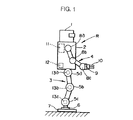
図1を参照して、本実施形態の二足歩行型ロボットRは、頭部1を上端部に支持する胴体2下部から一対の脚体3(図では便宜上、一本の脚体3のみを示す)が下方に延設され、また、胴体2上部の左右両側部から一対の腕体4(図では便宜上、一本の腕体4のみを示す)が延設されている。
【0026】
各脚体3は、その胴体2との連結箇所(股関節部分)と膝関節部分と足首関節部分とにそれぞれ股関節アクチュエータ5a、膝関節アクチュエータ5b及び足首関節アクチュエータ5cを備え、さらに、足首関節アクチュエータ5cの下側には、6軸力センサ6を介して脚体3の接地部分である足平部7が取着されている。この場合、本実施形態では、股関節アクチュエータ5aはロボットRの前後、左右及び上下方向の3軸回りの回転動作、膝関節アクチュエータ5bは、左右方向の1軸回りの回転動作、足首関節アクチュエータ5cは前後及び左右方向の2軸回りの回転動作を行うものであり、これらの各アクチュエータ5a〜5cを駆動することで、人間の脚とほぼ同様の脚体3の動作を行うことができるようになっている。尚、前記6軸力センサ6は、足平部7への作用力(ロボットRの前後、左右及び上下の3軸方向の力成分及びモーメント成分)を検出するものである。
【0027】
同様に、各腕体4は、胴体2との連結箇所(肩関節部分)と肘関節部分と手首関節部分とにそれぞれ肩関節アクチュエータ8a、肘関節アクチュエータ8b及び手首関節アクチュエータ8cを備え、該手首関節アクチュエータ8cに6軸力センサ9を介してハンド10が取着されている。この場合、肩関節アクチュエータ8aは、ロボットRの前後、左右及び上下方向の3軸回りの回転動作、肘関節アクチュエータ8bは、ロボットRの左右方向の1軸回りの回転動作、手首関節アクチュエータ8cは前後、左右及び上下方向の3軸回りの回転動作を行うものである。
【0028】
また、胴体2には、前述の各アクチュエータ5a〜5c及び8a〜8cを駆動・制御する制御ユニット11や、ロボットRの上体姿勢を示す胴体2の傾斜状態を図示しない加速度センサやレートジャイロを用いて検出する傾斜検出器12が備えられている。さらに、各脚体3の各アクチュエータ5a〜5cの箇所にはそれらの変位(各軸回りの回転角)を検出するアクチュエータ変位検出器13a〜13cが備えられ、同様に、各腕体4の各アクチュエータ8a〜8cの箇所にもアクチュエータ変位検出器(図示を省略する)が備えられている。以下、各脚体3の各アクチュエータ5a〜5cを脚用アクチュエータ5と総称し、また、これらに対応する各アクチュエータ変位検出器13a〜13cをアクチュエータ変位検出器13と総称する。
【0029】
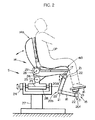
図2を参照して、ロボット操縦装置Sは、同図に仮想線で示すオペレータOPの上体を支持する上体支持機構として、オペレータOPが着座するシート14を備え、また、シート14に着座したオペレータOPの両足平を支持する足平支持機構15を備えている。尚、ロボット操縦装置Sは、さらにロボットRの各腕体4を操縦するための装置も備えているのであるが、これについては、ここでは図示及び説明を省略する。
【0030】
足平支持機構15は、ロボットRの両脚体3をオペレータOPの両足平の動きによって操縦するためのマスター装置を構成するものであり、シート14に着座したオペレータOPが各足平を載せる足平架台16と、この足平架台16をシート14の座部14aの前部の下面部に固設されたブラケット17に連結するリンク機構状の可動脚18とをそれぞれオペレータOPの両脚に対応して一対づつ具備し(図では便宜上、一つ足平架台16及び可動脚18のみを示す)、各足平架台16はそれに対応する可動脚18の先端部に6軸力センサ19を介して取着されている。尚、各足平架台16に載せたオペレータOPの各足平は図示しないバンド等により足平架台16に固定される。また、6軸力センサ19は、オペレータOPの各足平から足平架台16が受ける作用力(3軸方向の力成分及びモーメント成分)を検出する足平作用力検出手段である。
【0031】
各可動脚18は、そのつけ根部分(可動脚18とブラケット17との連結箇所)と、中間部分と、先端部分とにそれぞれ関節20a,20b,20cを備えており、その各関節20a,20b,20cにこれを駆動するマスター脚アクチュエータ21が設けられている。これらのマスター脚アクチュエーター21は、足平支持機構15の駆動手段を構成するものである。この場合、関節20aのマスター脚アクチュエータ21は、前後、左右及び上下の3軸回りの回転動作、関節20bのマスター脚アクチュエータ21は、左右方向の1軸回りの回転動作、関節20cのマスター脚アクチュエータ21は、前後及び左右方向の2軸回りの回転動作が行われるようになっている。そして、これらの各マスター脚アクチュエータ21の作動により、オペレータOPの足平の動きに合わせて足平架台16がオペレータOPの足平と一体的に動く(6自由度の動き)ようになっている。また、各マスター脚アクチュエータ21には、その変位を検出するアクチュエータ変位検出器22が備えられている。
【0032】
尚、上記のような足平支持機構15においては、各マスター脚アクチュエータ21の暴走時等にオペレータOPに過負荷がかかるのを防止するために、各マスター脚アクチュエータ21や各可動脚18の可動範囲に制限を設けておくことが好ましい。さらに、足平支持機構15の後述の作動時に、各マスター脚アクチュエータ21の負荷を軽減するために、可動脚18の自重を補償するためのバランスウェイトやバネを備えておくことが好ましい。
【0033】
また、シート14は、その座部14aが、前後方向の軸心23回りにアクチュエータ24により左右に傾動し(座部14aの左右の両側部が上下する)、さらに、左右方向の軸心25回りにアクチュエータ26により座部14aの前端部が上下する方向に傾動するように基台27上に支持されている。そして、シート14の背もたれ部14bは、左右方向の軸心28回りにアクチュエータ29により前後に傾動するように座部14aの後端部から起立され、この背もたれ部14bにオペレータOPの上体が図示しないバンド等により固定されるようになっている。このようなシート14の構造は、ロボットRの上体(胴体2)の傾斜姿勢を、オペレータOPが自身の上体の傾斜姿勢によりロボットRに指示したり、ロボットRの上体の姿勢の不安定さに応じて座部14aを傾動させたりするためのものであり、これについては、本願出願人が先に特願平8−343922号にて詳細に説明しているので、ここでは詳細な説明を省略する。
【0034】
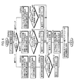
一方、本実施形態では、前述のロボットRやロボット操縦装置Sの動作制御を行うために、図3及び図4のブロック図に示す制御システムを備えている。
【0035】
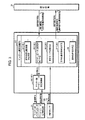
この制御システムは、その構成を大別すると、ロボット操縦装置S側に設けた制御ユニット30(図3)と、ロボットRに設けた前記制御ユニット11(図4)と、これらの制御ユニット30,11間での通信を行うための通信装置31とから構成されている。以下、制御ユニット30をマスター側制御ユニット30と称し、制御ユニット11をロボット側制御ユニット11と称する。尚、通信装置31の通信方式は有線及び無線のいずれの方式を使用してもよい。
【0036】
図3に示したマスター側制御ユニット30は、足平指示機構15の動作に関する制御を行うために、マスター脚主制御部32とマスター脚アクチュエータ変位制御部33とを具備している。
【0037】
マスター脚主制御部32は、その機能的構成として、足平指示機構15の各足平架台16の目標位置/姿勢を決定する足平目標位置/姿勢決定手段34と、各マスター脚アクチュエータ21の目標変位を算出して決定するアクチュエータ目標変位決定手段35と、各足平架台16に支持・固定したオペレータOPの各足平の動作モード(足平支持機構15の動作モード)を検出する動作モード判別手段36と、オペレータOPの両足平の相対的な位置/姿勢関係を検出する足平位置/姿勢検出手段37と、ロボットRの両脚体3を動作させるための脚体動作指令を通信装置31を介してロボット側制御ユニット11に与える脚体動作指令手段38とを有する。ここで、本発明の構成に対応させると、動作モード判別手段36及びオペレータ足平位置/姿勢検出手段37は足平動作状態検出手段39を構成し、また、足平目標位置/姿勢決定手段34及びアクチュエータ目標変位決定手段35は、マスター脚アクチュエータ変位制御部33と併せて、足平支持機構制御手段40を構成するものである。
【0038】
前記動作モード判別手段36が検出するオペレータOPの各足平の動作モードは、本実施形態では、ロボットRの歩行時における着床状態の脚体3(支持脚)の動作に対応する接地モード、ロボットRの遊脚側の脚体3を離床させて持ち上げる動作に対応する空中モード、及びロボットRの遊脚側の脚体3を下降させて着床させる動作(着床直前の動作)に対応する降下モードの3種類のモードである。そして、動作モード判別手段36は、ロボット側制御ユニット11から遊脚側の脚体3の着床情報(これについては後述する)が通信装置31を介して与えられたときから、その脚体3に対応するオペレータOPの足平の動作モードを接地モードとして検出し、さらにその接地モードの足平に対応する足平架台16に備えた前記6軸力センサ19によって、足平の持ち上げ動作による上向きの作用力が検出されたときから、オペレータOPの足平の動作モードを空中モードとして検出する。さらに、この空中モードの足平に対応する足平架台16の下降速度が所定の設定値を超えたときから、オペレータOPの足平の動作モードを降下モードとして検出する。尚、この降下モードを検出する際の足平架台16の下降速度は、例えば足平目標位置/姿勢決定手段34により後述の如く決定される足平架台16の目標位置/姿勢の変化速度により検出される。あるいは、速度センサ等を用いて上記下降速度を検出するようにしてもよい。
【0039】
前記足平目標位置/姿勢決定手段34は、動作モード判別手段36で検出される動作モードに応じて次のように各足平架台16の目標位置/姿勢を所定の制御サイクルタイム毎に決定する。すなわち、動作モードが接地モードであるオペレータOPの足平に対応する足平架台16については、該足平架台16のオペレータOPの上体(例えばオペレータOPの腰部分)に対する位置/姿勢が、ロボット側制御ユニット11から後述のように通信装置31を介して与えられるロボットRの脚体3(支持脚)の足平部7のロボットRの上体(ロボットRの腰部分)に対する位置/姿勢に対応したものとなるように該足平架台16の目標位置/姿勢を決定する。また、動作モードが空中モード又は降下モードであるオペレータOPの足平に対応する足平架台16については、その足平架台16に備えた前記6軸力センサ19により検出される作用力が減少する方向に該足平架台16の位置/姿勢を変化させるように該足平架台16の目標位置/姿勢を決定する。
【0040】
前記アクチュエータ目標変位決定手段35は、足平目標位置/姿勢決定手段34により決定された各足平架台16の目標位置/姿勢からそれに対応する各マスター脚アクチュエータ21の目標変位を算出して決定する。
【0041】
前記足平位置/姿勢検出手段37は、足平目標位置/姿勢決定手段34により決定された両足平架台16の目標位置/姿勢の相対的な位置/姿勢関係をオペレータOPの両足平の相対的な位置/姿勢関係として検出する。尚、このようなオペレータOPの両足平の相対的な位置/姿勢関係の検出は、例えば前記アクチュエータ変位検出器22による前記各マスター脚アクチュエータ21の変位検出値に基づいて行うようにしてもよい。
【0042】
前記脚体動作指令手段38は、動作モード判別手段36で検出された動作モードをロボットRの脚体3の着床/離床動作を行わしめるための着床/離床指令として通信装置31を介してロボット側制御ユニット11に与える。さらに、脚体動作指令手段38は、動作モードが降下モードとなった際に、足平位置/姿勢検出手段37によって検出されたオペレータOPの両足平の相対的な位置/姿勢関係に基づき、ロボットRの遊脚側の脚体3の足平部7の支持脚側の脚体3の足平部7に対する着床位置/姿勢を規定する着床足平位置/姿勢指令を決定し、それを通信装置31を介してロボット側制御ユニット11に与える。
【0043】
また、前記マスター脚アクチュエータ変位制御部33は、マスター脚主制御部32の前記アクチュエータ目標変位決定手段35により決定された目標変位と前記アクチュエータ変位検出器22により検出される各マスター脚アクチュエータ21の変位の検出値とに基づき、各マスター脚アクチュエータ21の変位を目標変位にフィードバック制御する。
【0044】
尚、マスター側制御ユニット30は、前述した構成の他、前記シート14の動作に関する制御部等(図示しない)も備えており、シート14の背もたれ部14bの傾斜姿勢に応じてロボットRの上体を傾斜させるための上体姿勢指令をロボットRに与えたり、ロボットRの上体姿勢の不安定さに応じてシート14の座部14aを傾動させたりするのであるが、これについては前記特願平8−343922号に本願出願人が詳細に説明しているので、ここでは説明を省略する。
【0045】
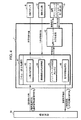
図4に示したロボット側制御ユニット11は、ロボットRの脚用アクチュエータ5の動作制御を行うために、ロボット脚主制御部41と脚用アクチュエータ変位制御部42とを具備している。
【0046】
ロボット脚主制御部41は、その主な機能的構成として、ロボットRの脚体3の動作形態(歩行形態)とロボットRの上体姿勢とを規定する基本的な目標歩容を生成する目標歩容生成手段43と、該目標歩容の所定の制御サイクル毎の瞬時値を決定する瞬時目標歩容決定手段44と、ロボットRの各脚用アクチュエータ5の目標変位を算出して決定するアクチュエータ目標変位決定手段45と、前記マスター側制御ユニット30に与えるロボットRの脚体3の動作情報を検出するロボット動作情報検出手段46とを有する。
【0047】
前記目標歩容生成手段43が生成する目標歩容は、ロボットRの足平部7の目標足平位置/姿勢や、ロボットRの歩行に際して支持脚側の脚体3の足平部7が床から受ける床反力の中心の目標軌道、ロボットRの上体(胴体2)の目標姿勢(上体の目標傾斜角)等の特徴を記述するパラメータにより構成される。そして、目標歩容生成手段43は、これらのパラメータを、前記マスター側制御ユニット30から与えられる前記着床/離床指令(動作モード)や着床足平位置/姿勢指令、さらにはシート14の背もたれ部14bの傾斜に応じた上体姿勢指令に従って、例えば脚体3の一歩分について生成する。この場合、足平部7が受ける床反力中心の目標軌道は、足平部7の接地面、あるいは両足平部7の接地面を含む最小面積の多角形(これは一般に支持多角形と言われる)内に存するように生成する。
【0048】
尚、このような目標歩容の生成は、本願出願人が例えば特開平5−318340号公報に詳細に開示しているので、ここでは、さらなる説明を省略する。
【0049】
前記瞬時目標歩容決定手段44は、目標歩容生成手段43により生成された基本の目標歩容から、所定の制御サイクル毎の目標歩容の瞬時値を算出し、さらにそれを適宜修正することで、最終的な目標歩容の瞬時値を決定する。この場合、目標歩容の瞬時値の修正にあたっては、ロボットRの姿勢が転倒しやすい不安定な姿勢となるのを排除するために、ロボットRの前記6軸力センサ6の検出値(足平部7が床から受ける作用力)や前記傾斜検出器12により検出されるロボットRの上体(胴体2)の傾斜姿勢に応じて該ロボットRの姿勢を安定化するための制御を行う。すなわち、この姿勢安定化制御では、瞬時目標歩容決定手段44は、所謂コンプライアンス制御によって、予期せぬ床の凹凸や傾斜によりロボットRの足平部7が受ける床反力の影響を該足平部7により吸収するように前記6軸力センサ6の検出値に応じて基本の目標歩容における目標足平位置/姿勢を修正し、また、ロボットRの上体姿勢の復元方向に足平部7に床反力が作用するように基本の目標歩容におけるロボットRの上体の目標姿勢と前記傾斜検出器12の検出値との偏差に応じて該目標足平位置/姿勢を修正する。さらに、ロボットRの上体姿勢の復元方向にロボットRの上体の慣性力が生じるように、基本の目標歩容におけるロボットRの上体の目標姿勢と前記傾斜検出器12の検出値との偏差に応じてロボットRの上体の目標姿勢を修正する。尚、このとき、ロボットRの上体の姿勢の他、上体の位置を修正するようにしてもよい。
【0050】
尚、このような姿勢安定化制御は本願出願人が例えば特開平5−337849号公報に詳細に開示しているので、ここでは、さらなる説明を省略する。
【0051】
前記アクチュエータ目標変位決定手段45は、瞬時目標歩容決定手段44により最終的に決定された目標歩容の瞬時値から、それに対応したロボットRの各脚用アクチュエータ5の目標変位を算出する。
【0052】
前記ロボット動作情報検出手段46は、ロボットRの支持脚側の脚体3の足平部7のロボットRの上体(腰部分)に対する位置/姿勢を検出するロボット足平位置/姿勢検出手段としての機能を有し、例えば前記アクチュエータ目標変位決定手段45により決定された各脚用アクチュエータ5の目標変位に基づき、支持脚側の足平部7のロボットRの上体に対する位置/姿勢を検出する。尚、この検出は、瞬時目標歩容決定手段44により決定された目標歩容の瞬時値や、前記アクチュエータ変位検出器13により検出された各脚用アクチュエータ5の変位検出値に基づいて行うようにしてもよい。
【0053】
このロボット動作情報検出手段46は、ロボットRの歩行に際しての遊脚側の脚体3の着地を検知する手段としての機能も有し、例えば前記6軸力センサ6により検出される遊脚側の脚体3の足平部7への作用力に基づき、その脚体3の着地を検知する。そして、ロボット動作情報検出手段46は、上記のように検出した足平部7のロボットRの上体に対する位置/姿勢の情報や、着地情報を脚体3の動作情報として、通信装置31を介してマスター側制御ユニット30のマスター脚主制御部32に与える。
【0054】
また、脚用アクチュエータ変位制御部42は、ロボット脚主制御部41の前記アクチュエータ目標変位決定手段45により決定された目標変位と前記アクチュエータ変位検出器13により検出される各脚用アクチュエータ5の変位の検出値とに基づき、各脚用アクチュエータ5の変位を目標変位にフィードバック制御する。
【0055】
次に、本実施形態のシステムにおいてロボットRの歩行(移動)を行う場合の作動を説明する。
【0056】
シート14に着座したオペレータOPがロボットRの歩行を行わしめようとするときには、オペレータOPは、ロボットRに行わせようとする歩行形態で、各足平架台16に載せて固定した自身の足平を動かす。すなわち、オペレータOPはこれから踏み出そうとする足平を持ち上げ、次いで、該足平を着床を行おうとする位置及び姿勢に向かって下降させる動作を各脚について繰り返す。
【0057】
このとき、マスター側制御ユニット30のマスター脚主制御部32は、足平支持機構15の各可動脚18について所定の制御サイクルで図5のフローチャートに示す処理を行う。
【0058】
すなわち、マスター脚主制御部32は、まず、ロボット側制御ユニット11から通信装置31を介してロボットRの脚体動作情報(ロボットRの着地情報、足平位置/姿勢情報)を受信した後(STEP5−0)、前記動作モード判別手段36によって今現在検出されているオペレータOPの足平の動作モードを判別する(STEP5−1)。この場合、動作モード判別手段36が検出する動作モードの初期モード(ロボットRの操縦を開始する際のモード)は接地モードである。
【0059】
そして、上記の判別で動作モードが接地モードである場合には、マスター脚主制御部32は、前記足平目標位置/姿勢決定手段34によって、前述の如くロボット側制御ユニット11のロボット脚主制御部41から与えられるロボットRの現在の支持脚側の脚体3の足平部7のロボットRの上体(腰部分)に対する位置/姿勢情報に応じて、それに対応した足平架台16の目標位置/姿勢(オペレータOPの腰部分に対する目標位置/姿勢)を決定する(STEP5−2)。つまり、ロボットRの支持脚側の脚体3に対応する足平架台16の目標位置/姿勢は、そのオペレータOPの腰部分に対する位置/姿勢関係が、該脚体3の足平部7のロボットRの腰部分に対する位置/姿勢関係と同じような関係になるように決定される。
【0060】
さらに、マスター脚主制御部32は、前記動作モード判別手段36によって、前記6軸力センサ19により上向きの作用力が検出されたか否かを判断する(STEP5−3)。このとき、上向きの作用力が検出された場合、すなわち、オペレータOPが足平を持ち上げた場合には、動作モード判別手段36によって、オペレータOPの足平の動作モードが接地モードから空中モードに移行したことが検出され(STEP5−4)、さらに後述のSTEP5−13の処理に移行する。また、STEP5−3で上向きの作用力が検出されない場合には、動作モード判別手段36が接地モードを検出したまま、後述のSTEP5−13の処理に移行する。
【0061】
STEP5−1の判別で、今現在、動作モード判別手段36によって検出されている動作モードが空中モードである場合には、マスター脚主制御部32は、足平目標位置/姿勢決定手段34によって、6軸力センサ19により検出される作用力の大きさが減少する方向に現在の足平架台16の目標位置/姿勢を変化させて、新たな目標位置/姿勢を決定する(STEP5−5)。換言すれば、足平架台16に載せられたオペレータOPの足平の動きに追従させるように足平架台16の目標位置/姿勢を決定する。そして、マスター脚主制御部32は、動作モード判別手段36によって、足平架台16の目標位置/姿勢の下降速度が所定の設定値を超えたか否かを判断する(STEP5−6)。このとき、下降速度>設定値となった場合、すなわち、オペレータOPがロボットRの遊脚側の脚体3の着床を意図した足平の動作を行った場合には、動作モード判別手段36によって、オペレータOPの足平の動作モードが空中モードから降下モードに移行したことが検出され(STEP5−7)、さらに後述のSTEP5−13の処理に移行する。また、STEP5−6で下降速度≦設定値である場合には、動作モード判別手段36が空中モードを検出したまま、後述のSTEP5−13の処理に移行する。
【0062】
STEP5−1の判別で、今現在、動作モード判別手段36によって検出されている動作モードが降下モードである場合には、マスター脚主制御部32は、足平目標位置/姿勢決定手段34によって、6軸力センサ19により検出される下向きの作用力の大きさが減少する方向に現在の足平架台16の目標位置/姿勢を変化させることで、足平架台16をオペレータOPの足平の動きに追従させるように新たな目標位置/姿勢を決定する(STEP5−8)。さらに、マスター脚主制御部32は、前記足平位置/姿勢検出手段37によって前述の如く検出される、現在の降下モードのオペレータOPの足平を支持した足平架台16の目標位置/姿勢と他方の足平(接地モードの足平)を支持した足平架台16との相対的位置/姿勢関係に基づき、前記脚体動作指令手段38によって、降下モードの足平に対応するロボットRの脚体3の足平部7の着床の際の着床足平位置/姿勢指令を決定し(STEP5−9)、その着床足平位置/姿勢指令を通信装置31を介してロボット脚主制御部41に送信する(STEP5−10)。尚、上記着床足平位置/姿勢指令の決定に際しては、今現在(空中モードから降下モードに移行した際)のオペレータOPの両足平の相対的な位置/姿勢関係により決定してもよいが、今現在のオペレータOPの両足平の位置/姿勢の変化速度等から両足平の将来的な位置/姿勢を予測し、その予測した位置/姿勢の相対的な位置/姿勢関係によって、上記着床足平位置/姿勢指令を決定するようにしてもよい。
次いで、マスター脚主制御部32は、前記動作モード判別手段36によって、ロボットRのロボット脚主制御部41からオペレータOPの降下モードの足平に対応するロボットRの脚体3の着地情報(着床した旨の情報)が与えられた否かを判断する(STEP5−11)。このとき、その着地情報が与えられた場合には、動作モード判別手段36によって、オペレータOPの足平の動作モードが空中モードから降下モードに移行することが検出され(STEP5−12)、さらにSTEP5−13の処理に移行する。また、STEP5−12で着床情報が与えられていない場合には、動作モード判別手段36によって降下モードが検出されたままSTEP5−13の処理に移行する。
【0063】
前記STEP5−13においては、マスター脚主制御部32は、前記脚体動作指令手段38によって、現在動作モード判別手段36によって検出されている動作モードをロボットRの足平部7の着床/離床指令として通信装置31を介してロボット脚主制御部41に送信する。
【0064】
次いで、マスター脚主制御部32は、アクチュエータ目標変位決定手段35によって、各足平架台16の現在の目標位置/姿勢に対応した各マスター脚アクチュエータ21の目標変位を決定し(STEP5−14)、さらに、その目標変位をマスター脚アクチュエータ変位制御部33に与えた後(STEP5−15)、今回の制御サイクルの処理を終了する。
【0065】
このようにして、マスター脚主制御部32から各マスター脚アクチュエータ21の目標変位が与えられたマスター脚アクチュエータ変位制御部33は、その目標変位に従って各マスター脚アクチュエータ21をフィードバック制御する。
【0066】
以上のようなマスター側制御ユニット30における制御処理により、ロボットRの支持脚側の脚体3に対応する足平架台16は、ロボットRの上体(腰部分)に対する足平部7の相対的位置/姿勢に対応した位置/姿勢に制御され、また、遊脚側の脚体3に対応する足平架台16は、オペレータOPの足平の動きに追従して動く。
【0067】
尚、本実施形態では、前記動作モードは、前述の3種類のモードの他、図示しない操縦開始スイッチがOFF状態とされたロックモードがあり、このロックモードでは、足平架台16は動かないように固定される。
【0068】
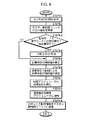
一方、前述のようなロボット操縦装置S側での動作(ロボットRの脚体3の操縦操作)が行われたとき、ロボットR側では、ロボット脚主制御部41は、所定の制御サイクルで図6のフローチャートに示す処理を行う。
【0069】
すなわち、ロボット脚主制御部41は、ロボットRに備えられた前記傾斜検出器12や6軸力センサ6等のセンサの出力を読み込み(STEP6−1)、さらにマスター側制御ユニット30から通信装置31を介して与えられる前述の脚体動作指令(着床/離床指令(動作モード)や着床の際の足平位置/姿勢指令)等を受信する(STEP6−2)。
【0070】
次いで、ロボット脚主制御部41は、オペレータOPのいずれか一方の足平の動作モードが前記空中モードから降下モードに切り替わった状態であるか否か(着床要求が有るか否か)を判断する(STEP6−3)。このとき、降下モードへの切り替わりの状態である場合には、ロボット脚主制御部41は、前記目標歩容生成手段43によって、上記降下モードに切り替わったオペレータOPの足平に対応するロボットRの脚体3(今現在の状態では、この脚体3はまだ着床状態にある)の一歩分について、前述の通り脚体動作指令等に従って前記目標歩容を生成する(STEP6−4)。尚、STEP6−3で、オペレータOPのいずれの足平も、その動作モードが前記空中モードから降下モードに切り替わった状態でない場合(オペレータOPの一方の足平が接地モードで、他方の足平が空中モードである場合)には、STEP6−4での目標歩容の生成は行われない(既に生成されている)。
【0071】
次いで、ロボット脚主制御部41は、前述の如く、目標歩容生成手段43によって生成された基本の目標歩容から、前記瞬時目標歩容決定手段44によって、現在の制御サイクルにおける目標歩容の瞬時値を算出した後(STEP6−5)、さらに、その瞬時値を前記姿勢安定化制御によって適宜修正する(STEP6−6)。
【0072】
次いで、ロボット脚主制御部41は、上記のように瞬時目標歩容決定手段35により修正した目標歩容の瞬時値から、前記アクチュエータ目標変位決定手段45によって、該瞬時値に対応した今回の制御サイクルにおける各脚体3の各脚用アクチュエータ5の目標変位を算出し(STEP6−7)、それを脚用アクチュエータ変位制御部42に指令する(STEP6−8)。このとき、脚用アクチュエータ変位制御部42は指令された目標変位に従って各脚用アクチュエータ5の変位を該目標変位にフィードバック制御する。
【0073】
そして、この後、ロボット脚主制御部41は、今回の制御サイクルにおいて前記動作情報検出手段46によって検出される、ロボットRの支持脚側の脚体3の現在の足平位置/姿勢情報(ロボットRの上体の腰部分に対する相対的な足平位置/姿勢)や遊脚側の脚体3の着地情報から成る脚体動作情報を通信回路31を介してマスター側制御ユニット30に送信して(STEP6−9)、今回の制御サイクルの処理を終了する。
【0074】
以上のようなロボットR側での作動により、ロボットRは自己の姿勢の安定化を自律的に図りつつ、概ね、オペレータOPの足平の動作と同じような形態で歩行する。尚、この時のロボットRの脚体3の動作は、オペレータOPの足平の動きに対して一歩分遅れて行われる。
【0075】
このようなロボットRの遠隔制御システムによれば、オペレータOPは、自身の足平の動きによって、ロボットRの脚体3の動作を該ロボットRに指令し、その指令に従ってロボットRの脚体3の動作が行われるため、オペレータOPは自身の足平の動きを、ロボットRの脚体3の実際の動きとして感覚的に認識することができ、これにより、オペレータOPは確実にロボットRの脚体3の所望の動作を行わしめることができる。
【0076】
この場合、本実施形態では、ロボットRの脚体3の着床の際の位置/姿勢は、前記降下モードのオペレータOPの足平の位置/姿勢と、他方の接地モードのオペレータOPの足平の位置/姿勢との相対的な位置/姿勢関係によって規定されるため、オペレータOPは、持ち上げた足平(ロボットRの遊脚側の脚体3に対応する足平)を他方の足平(支持脚側の脚体3に対応する足平)に対して、所望の位置/姿勢に向かって下降させることで、ロボットRの歩行時の歩幅や歩行方向を、あたかも自身が実際に歩行している場合と同様の感覚で、ロボットRに行わしめることができる。
【0079】
また、オペレータOPの足平を支持する足平架台16は、オペレータOPの足平の動きに追従して駆動されるため、オペレータOPが自身の足平を動かすためにさほど大きな労力を要することがなく、容易にロボットRの操縦を行うことができる。
【0080】
尚、本実施形態では、ロボット操縦装置Sの足平架台16がオペレータOPの足平から受ける作用力を6軸力センサ19を用いて検出するようにしたが、各マスター脚アクチュエータ21の駆動力を検出するセンサを設けておき、それらのセンサの出力により足平架台16が受ける作用力を検出するようにしてもよい。但し、この場合には、可動脚18等の自重や慣性力の影響を補償する必要がある。
【0081】
また、本実施形態は、足平支持機構15をリンク機構により構成したが、XYZテーブル等を用いて構成してもよい。あるいは、例えばオペレータOPに履かせるシューズ等を、回転ドラムにより巻き取り可能な複数のワイヤーにより吊るしておき、それらのワイヤーを回転ドラムに巻き取ったり、引き出したりすることで、オペレータOPの足平の動きに合わせて上記シューズ等の位置/姿勢を制御するようにしてもよい。
【0082】
また、本実施形態では、ロボットRの遊脚側の脚体3の空中における位置/姿勢や動作軌跡については、ロボット操縦装置Sから指令を与えていないが、前記空中モードの途中におけるオペレータOPの足平の位置/姿勢や動作軌跡をロボットRに指令するようにしてもよい。
【0083】
また、本実施形態では、ロボット操縦装置S上でのオペレータOPの足平の着床動作(前記空中モードから降下モードに移行する動作)を、オペレータOPの足平の下降速度に基づき判断するようにしたが、該足平の下降加速度や、その下降加速度の変化率、前記6軸力センサ19の検出値もしくはその検出値の変化率等によってオペレータOPの足平の着床動作(着床の意思)を判断するようにしてもよい。あるいは、足平架台16に例えばオペレータOPの足指により操作可能なスイッチを設けておき、そのスイッチ操作の有無によって、オペレータOPの足平の着床の意思を判断するようにしてもよい。
【0084】
また、本実施形態では、ロボットRの操縦に際してシート14の背もたれ部14bや座部14aが動くものを示したが、ロボットRの上体姿勢を別途の操縦装置により指令したり、あるいはロボットRの上体を傾けたりする必要がないような場合には、シート14は固定的なもの(アクチュエータ等を具備しないもの)を使用してもよい。
【0085】
さらに本実施形態では、オペレータOPの上体を支持するためにシート14を使用したが、これに限らず、オペレータOPの上体を支持できるものであれば、他の構造のものを使用してもよい。
【0086】
また、本実施形態では、ロボットRは、ある程度、その姿勢を自律的に安定化するための構成を備えたものを示したが、そのような構成を具備していないものであってもよい。
【図面の簡単な説明】
【図1】本発明の第1の実施形態のシステムにおけるロボットを示す図。
【図2】本発明の第1の実施形態のシステムにおけるロボット操縦装置を示す図。
【図3】図2のロボット操縦装置側の制御システムを示す図。
【図4】図1のロボット側の制御システムを示す図。
【図5】図3の制御システムを作動を説明するためのフローチャート。
【図6】図4の制御システムの作動を説明するためのフローチャート。
【符号の説明】
OP…オペレータ、R…二足歩行型ロボット、14…シート(上体支持機構)、15…足平支持機構、19…6軸力センサ(足平作用力検出手段)、21…マスター脚アクチュエータ(駆動手段)、37…オペレータの足平位置/姿勢検出手段、39…足平動作状態検出手段、40…足平支持機構制御手段、46…動作情報検出手段(ロボット足平位置/姿勢検出手段)。[0001]
BACKGROUND OF THE INVENTION
The present invention relates to a remote control system for a biped robot.
[0002]
[Prior art]
2. Description of the Related Art Conventionally, a robot remote control system is known that commands a robot operation by operating a joystick or other operator.
[0003]
In this type of system, for example, when a biped robot is walked forward, an operator operates an operation element such as a joystick in a direction corresponding to the forward movement side of the robot. The robot's walking speed is commanded according to the operation amount.
[0004]
However, in such a system, the operation of each leg when the biped robot is walking (an operation that alternately repeats the landing and leaving of both legs) and the operation of the operator corresponding to the operation are completely different. Since it takes a form, it is difficult for the operator to understand the actual movement of the leg of the robot. For example, when commanding the walking speed of a biped robot by the operation amount of the operation element, even if the walking speed of the robot is faster or slower than the walking speed assumed by the operator, The operator cannot know sensuously from the amount of operation.
[0005]
For this reason, in the system as described above, skill is required to operate the operation element in order to ensure that the robot performs the operation of the robot intended by the operator.
[0006]
Also, in a robot remote control system, when an operator wears a master device on the whole body and tries to walk the robot, for example, the operator actually walks and the walking motion is transferred from the master device to the robot. What is commanded is known. .
[0007]
However, in such a system, it is necessary to provide equipment on the master device side that has the same environment as the robot's operating environment (floor shape to move the robot, its size, etc.). Due to such restrictions, it has been difficult to move the robot over a wide range under various environments.
[0008]
[Problems to be solved by the invention]
In view of such a background, the present invention makes it possible for an operator to make a desired movement of a leg of a robot while performing a walking or the like of a biped walking robot while the operator recognizes the movement of the leg of the robot by his / her own operation. It is an object of the present invention to provide a remote control system for a biped robot that can perform the above-described operations and can move the robot over a wide range under various environments.
[0009]
[Means for Solving the Problems]
The remote control systems according to the first, second and third aspects of the present invention for solving the above-mentioned problems are autonomous postures such that the foot moves according to a command corresponding to the operation of the foot of the operator. A biped walking robot remote control system capable of walking by moving two legs while stabilizing the body, a body support mechanism including a seat on which the operator is seated, and A foot support mechanism having a foot platform on which both feet of the operator seated on the seat are placed, and a foot motion that detects the operating state of each foot of the operator placed on the foot platform of the foot support mechanism State detection means, and leg motion command means for giving the command to the biped robot according to the motion state of each foot of the operator detected by the foot motion state detection means. Features. Further, in the remote control system according to the first aspect of the present invention, the foot motion state detecting means is further provided in the motion state of each foot of the operator corresponding to the landing motion of each leg of the biped robot. Operator foot position / posture detection means for detecting the relative positional relationship between the operator's feet is provided, and the leg motion command means is detected by the operator foot position / posture detection means. Relative landing position based on the position of the foot part of the other leg of the leg part of the leg on the free leg side of the biped robot based on the relative position of the flat Means for providing the biped walking robot with the command that defines the above. The remote control system according to the second aspect of the present invention is the remote control system according to the second aspect of the present invention, wherein the foot motion state detecting means is configured so that the operator in the foot motion state corresponding to the landing motion of each leg of the biped robot An operator foot position / posture detecting means for detecting a relative posture relation between both feet of the foot, wherein the leg motion command means is the position of the foot of the operator detected by the operator foot position / posture detecting means. Defines the relative landing posture based on the posture of the foot of the leg on the free leg side of the biped robot, based on the relative posture relationship Means for giving the command to the biped robot. The remote control system according to a third aspect of the present invention is the remote control system according to the third aspect of the present invention, wherein the foot motion state detection means is configured to operate the operator in the foot motion state corresponding to the landing motion of each leg of the biped robot. An operator's foot position / posture detecting means for detecting a relative positional relationship and a relative posture relation of the two feet, and the leg motion command means is detected by the operator's foot position / posture detecting means. The position of the foot part of the leg of the leg on the free leg side of the biped walking robot based on the relative positional relationship between the two feet of the operator is used as a reference. Based on the relative landing position and the relative posture relationship between the two feet of the operator detected by the operator foot position / posture detecting means, the leg on the free leg side of the biped robot is determined. Foot of the other leg of the foot The instruction defining the relative implantation orientation relative to the orientation of the parts, characterized in that it comprises means for providing to the two-legged robot.
[0010]
According to the present invention, when operating the legs of the biped robot, the operator supports his / her upper body on the upper body support mechanism and supports his / her both feet on the foot support. Supported by the mechanism, in this state, the operator moves both feet of the operator in such a form that the operator wants to operate the legs of the biped robot (for example, a walking form). At this time, the foot motion state detection means detects the motion state of each foot of the operator (for example, the motion of each foot of the operator corresponding to the floor leaving motion of each leg of the biped robot) The movement of each foot of the operator corresponding to the body's landing movement, or the position, posture, or temporal change of each foot of the foot, indicating the content of the foot movement) In response to the detected motion state of each foot of the operator, the leg motion command means gives the leg motion command to the robot. Then, the leg of the robot moves based on the given operation command.
[0011]
Therefore, the operator operates the leg of the biped robot by his / her own foot motion, and can recognize the motion of the robot's leg by his / her foot motion. In addition, the operator can cause the robot's legs to perform the required motion by moving the foot at the location where the upper body is supported by the upper body support mechanism. It is not necessary for the operator to move, and the robot can be moved arbitrarily in the operating environment by simply moving the foot in consideration of the operating environment of the robot.
[0012]
Thus, according to the system of the present invention, the operator can surely perform the desired movement of the robot leg while sensibly recognizing the movement of the robot leg by his own operation (foot movement). The robot can be moved over a wide range in various environments.
[0016]
According to the remote control system of the first aspect of the present invention, the relative position of the foot part of the leg on the free leg side of the biped robot is relative to the position of the foot part of the other leg. The “landing position” is determined based on the “relative positional relationship” of the two feet of the operator in the motion state of each foot of the operator corresponding to the landing motion of each leg of the robot. Further, according to the remote control system of the second aspect of the present invention, the “relative” is based on the posture of the foot of the leg on the free leg side of the biped robot and the foot of the other leg. Is determined based on the “relative posture relationship” of the two feet of the operator in the motion state of each foot of the operator corresponding to the landing motion of each leg of the robot. Furthermore, according to the remote control system of the third aspect of the present invention, the relative position of the foot portion of the leg on the free leg side of the biped walking robot is determined based on the position of the foot portion of the other leg. The `` landing position '' and the `` relative landing position '' based on the posture of the foot of the other leg are the respective positions of the foot of the operator corresponding to the landing movement of each leg of the robot. It is determined based on each of “relative positional relationship” and “relative posture relationship” of both feet of the operator in the motion state.For this reason, when the operator walks the robot, when performing the operation of the foot of the operator corresponding to the landing operation of one leg of the robot, Posture relationshipOne or bothAs the operator walks, the stride and the walking direction of the robot can be controlled. Thereby, the operator can perform the desired motion of the robot leg with an integrated sense of the motion of his / her foot and the motion of the leg of the robot.
[0020]
The remote control system of the present invention isFoot action force detection means for detecting the action force received by each foot of the operator by the foot support mechanism, drive means for driving the foot support mechanism, and action detected by the foot action force detection means Foot support mechanism control means for controlling the drive means so that the foot support mechanism follows the movement of each foot of the operator based on force.Characterized by.
[0021]
Thus, the foot support mechanism detects the acting force received from each foot of the operator, and the foot support mechanism is made to follow the movement of each foot of the operator based on the detected acting force. By controlling the driving means of the mechanism, the operator can freely move his / her foot supported by the foot support mechanism with little effort to perform the desired motion of the leg of the robot. Operation can be performed smoothly.
[0022]
In order to cause the foot support mechanism to follow the movement of each foot of the operator in this way, for example, the foot support mechanism control means may change the acting force detected by the foot action force detecting means. What is necessary is just to control the said drive means so that the said foot | leg support mechanism may be moved to the position and / or attitude | position which reduce this.
[0023]
DETAILED DESCRIPTION OF THE INVENTION
An embodiment of the present invention will be described with reference to FIGS.
[0024]
First, FIG.1 and FIG.2 has each shown the biped walking type robot in the system of this embodiment, and the control apparatus of this robot.
[0025]
Referring to FIG. 1, a biped robot R of the present embodiment has a pair of legs 3 (only one
[0026]
Each
[0027]
Similarly, each
[0028]
Further, the
[0029]
Referring to FIG. 2, the robot control apparatus S includes a
[0030]
The
[0031]
Each
[0032]
In the
[0033]
Further, the
[0034]
On the other hand, in the present embodiment, in order to control the operation of the robot R and the robot control device S described above, a control system shown in the block diagrams of FIGS. 3 and 4 is provided.
[0035]
This control system can be broadly divided into a control unit 30 (FIG. 3) provided on the robot control device S side, the control unit 11 (FIG. 4) provided on the robot R, and the
[0036]
The master-side control unit 30 shown in FIG. 3 includes a master leg
[0037]
The master leg
[0038]
In this embodiment, the operation mode of each foot of the operator OP detected by the operation
[0039]
The foot target position /
[0040]
The actuator target
[0041]
The foot position /
[0042]
The leg operation command means 38 uses the operation mode detected by the operation mode determination means 36 as a landing / leaving instruction for performing the landing / leaving operation of the
[0043]
Further, the master leg actuator
[0044]
The master-side control unit 30 includes a control unit (not shown) related to the operation of the
[0045]
The robot-
[0046]
The robot leg
[0047]
The desired gait generated by the desired gait generating means 43 is the desired foot position / posture of the
[0048]
The generation of such a desired gait is disclosed in detail in, for example, Japanese Patent Application Laid-Open No. 5-318340 by the applicant of the present application, and further description is omitted here.
[0049]
The instantaneous target
[0050]
Such posture stabilization control is disclosed in detail by the applicant of the present application in, for example, Japanese Patent Laid-Open No. 5-337849, and further description thereof is omitted here.
[0051]
The actuator target
[0052]
The robot motion information detection means 46 is a robot foot position / posture detection means for detecting the position / posture of the
[0053]
The robot motion information detection means 46 also has a function as a means for detecting the landing of the
[0054]
Further, the leg actuator
[0055]
Next, the operation when the robot R walks (moves) in the system of this embodiment will be described.
[0056]
When the operator OP seated on the
[0057]
At this time, the master leg
[0058]
That is, the master leg
[0059]
When the operation mode is the ground contact mode in the above determination, the master leg
[0060]
Further, the master leg
[0061]
If the operation mode currently detected by the operation
[0062]
If the operation mode currently detected by the operation
Next, the master leg
[0063]
In STEP 5-13, the master leg
[0064]
Next, the master leg
[0065]
In this way, the master leg actuator
[0066]
By the control processing in the master side control unit 30 as described above, the
[0067]
In this embodiment, in addition to the above-described three types of modes, the operation mode includes a lock mode in which an operation start switch (not shown) is turned off. In this lock mode, the
[0068]
On the other hand, when the above-described operation on the robot control device S side (control operation of the
[0069]
That is, the robot leg
[0070]
Next, the robot leg
[0071]
Next, as described above, the robot leg
[0072]
Next, the robot leg
[0073]
Thereafter, the robot leg
[0074]
By the operation on the side of the robot R as described above, the robot R walks in the same manner as the foot movement of the operator OP while autonomously stabilizing its posture. Note that the movement of the
[0075]
According to such a remote control system for the robot R, the operator OP commands the robot R to operate the
[0076]
In this case, in this embodiment, the position / posture of the
[0079]
Further, since the
[0080]
In this embodiment, the acting force received by the
[0081]
In the present embodiment, the
[0082]
In this embodiment, no command is given from the robot control device S regarding the position / orientation and motion trajectory of the
[0083]
In the present embodiment, the foot landing operation of the operator OP on the robot control device S (the operation of shifting from the aerial mode to the lowering mode) is determined based on the lowering speed of the foot of the operator OP. However, depending on the descending acceleration of the foot, the rate of change of the descending acceleration, the detected value of the six-
[0084]
In the present embodiment, the seat 14a and the seat 14a move when the robot R is operated. However, the robot R may be instructed by a separate control device, or the robot R When it is not necessary to tilt the upper body, the
[0085]
Further, in the present embodiment, the
[0086]
In the present embodiment, the robot R is shown to have a configuration for autonomously stabilizing its posture to some extent, but the robot R may not have such a configuration.
[Brief description of the drawings]
FIG. 1 is a diagram showing a robot in a system according to a first embodiment of the present invention.
FIG. 2 is a diagram showing a robot control apparatus in the system according to the first embodiment of the present invention.
FIG. 3 is a diagram showing a control system on the robot control apparatus side in FIG. 2;
4 is a diagram showing a control system on the robot side in FIG. 1;
FIG. 5 is a flowchart for explaining the operation of the control system of FIG. 3;
6 is a flowchart for explaining the operation of the control system of FIG. 4;
[Explanation of symbols]
OP ... operator, R ... bipedal walking robot, 14 ... seat (upper body support mechanism), 15 ... foot support mechanism, 19 ... six-axis force sensor (foot action force detection means), 21 ... master leg actuator ( Drive means), 37 ... operator foot position / posture detection means, 39 ... foot motion state detection means, 40 ... foot support mechanism control means, 46 ... motion information detection means (robot foot position / posture detection means) .
Claims (5)
前記オペレータが着座するシートを備えた上体支持機構と、該上体支持機構のシートに着座したオペレータの両足平が載せられる足平架台を備えた足平支持機構と、該足平支持機構の足平架台に載せられたオペレータの各足平の動作状態を検出する足平動作状態検出手段と、該足平動作状態検出手段により検出されたオペレータの各足平の動作状態に応じて前記指令を前記二足歩行型ロボットに与える脚体動作指令手段とを備え、
前記足平動作状態検出手段が、前記二足歩行型ロボットの各脚体の着床動作に対応するオペレータの各足平の動作状態における該オペレータの両足平の相対的な位置関係を検出するオペレータ足平位置/姿勢検出手段を備え、前記脚体動作指令手段が、前記オペレータ足平位置/姿勢検出手段により検出された前記オペレータの両足平の相対的な位置関係に基づいた、前記二足歩行型ロボットの遊脚側の脚体の足平部の、他方の脚体の足平部の位置を基準とする相対的な着床位置を規定する前記指令を、該二足歩行型ロボットに与える手段を備えていることを特徴とする二足歩行型ロボットの遠隔制御システム。 This is a remote control system for a biped walking robot that can walk by moving two legs while autonomously stabilizing the posture so that the foot moves according to the command according to the operation of the operator's foot. There ,
And upper body support mechanism having a seat in which the operator is seated, the foot support mechanism operator both feet is provided with a foot platform that rests seated on the seat of the upper body supporting mechanism, the foot support mechanism A foot motion state detecting means for detecting the motion state of each foot of the operator placed on the foot stand, and the command according to the motion state of each foot of the operator detected by the foot motion state detecting means A leg motion command means for providing the biped robot with
An operator for detecting the relative positional relationship between the two feet of the operator in the motion state of each foot of the operator corresponding to the landing motion of each leg of the biped walking robot. The biped walking system comprising foot position / posture detection means, wherein the leg movement command means is based on a relative positional relationship between the feet of the operator detected by the operator foot position / posture detection means. The biped walking robot is provided with the command that defines the relative landing position of the foot part of the leg on the free leg side of the robot, relative to the position of the foot part of the other leg. the remote control system of the biped robot, characterized in that it comprises means.
前記オペレータが着座するシートを備えた上体支持機構と、該上体支持機構のシートに着座したオペレータの両足平が載せられる足平架台を備えた足平支持機構と、該足平支持機構の足平架台に載せられたオペレータの各足平の動作状態を検出する足平動作状態検出手段と、該足平動作状態検出手段により検出されたオペレータの各足平の動作状態に応じて前記指令を前記二足歩行型ロボットに与える脚体動作指令手段とを備え、
前記足平動作状態検出手段が、前記二足歩行型ロボットの各脚体の着床動作に対応するオペレータの各足平の動作状態における該オペレータの両足平の相対的な姿勢関係を検出するオペレータ足平位置/姿勢検出手段を備え、前記脚体動作指令手段が、前記オペレータ足平位置/姿勢検出手段により検出された前記オペレータの両足平の相対的な姿勢関係に基づいた、前記二足歩行型ロボットの遊脚側の脚体の足平部の、他方の脚体の足平部の姿勢を基準とする相対的な着床姿勢を規定する前記指令を、該二足歩行型ロボットに与える手段を備えていることを特徴とする二足歩行型ロボットの遠隔制御システム。 This is a remote control system for a biped walking robot that can walk by moving two legs while autonomously stabilizing the posture so that the foot moves according to the command according to the operation of the operator's foot. There ,
And upper body support mechanism having a seat in which the operator is seated, the foot support mechanism operator both feet is provided with a foot platform that rests seated on the seat of the upper body supporting mechanism, the foot support mechanism A foot motion state detecting means for detecting the motion state of each foot of the operator placed on the foot stand, and the command according to the motion state of each foot of the operator detected by the foot motion state detecting means A leg motion command means for providing the biped robot with
An operator for detecting the relative posture relationship between the feet of the operator in the motion state of each foot of the operator corresponding to the landing motion of each leg of the biped walking robot. The biped walking system comprising foot position / posture detection means, wherein the leg motion command means is based on a relative posture relationship between both feet of the operator detected by the operator foot position / posture detection means. The biped walking robot is instructed to specify the relative landing posture of the foot portion of the leg on the free leg side of the robot and relative to the posture of the foot portion of the other leg. the remote control system of the biped robot, characterized in that it comprises means.
前記オペレータが着座するシートを備えた上体支持機構と、該上体支持機構のシートに着座したオペレータの両足平が載せられる足平架台を備えた足平支持機構と、該足平支持機構の足平架台に載せられたオペレータの各足平の動作状態を検出する足平動作状態検出手段と、該足平動作状態検出手段により検出されたオペレータの各足平の動作状態に応じて前記指令を前記二足歩行型ロボットに与える脚体動作指令手段とを備え、
前記足平動作状態検出手段が、前記二足歩行型ロボットの各脚体の着床動作に対応するオペレータの各足平の動作状態における該オペレータの両足平の相対的な位置関係と、相対的な姿勢関係とを検出するオペレータ足平位置/姿勢検出手段を備え、前記脚体動作指令手段が、前記オペレータ足平位置/姿勢検出手段により検出された前記オペレータの両足平の相対的な位置関係に基づいた、前記二足歩行型ロボットの遊脚側の脚体の足平部の、他方の脚体の足平部の位置を基準とする相対的な着床位置と、前記オペレータ足平位置/姿勢検出手段により検出された前記オペレータの両足平の相対的な姿勢関係に基づいた、前記二足歩行型ロボットの遊脚側の脚体の足平部の、他方の脚体の足平部の姿勢を基準とする相対的な着床姿勢とを規定する前記指令を、該二足歩行型ロボットに与える手段を備えていることを特徴とする二足歩行型ロボットの遠隔制御システム。 This is a remote control system for a biped walking robot that can walk by moving two legs while autonomously stabilizing the posture so that the foot moves according to the command according to the operation of the operator's foot. There ,
And upper body support mechanism having a seat in which the operator is seated, the foot support mechanism operator both feet is provided with a foot platform that rests seated on the seat of the upper body supporting mechanism, the foot support mechanism A foot motion state detecting means for detecting the motion state of each foot of the operator placed on the foot stand, and the command according to the motion state of each foot of the operator detected by the foot motion state detecting means A leg motion command means for providing the biped robot with
The foot motion state detecting means includes a relative positional relationship between both feet of the operator in the motion state of each foot of the operator corresponding to the landing motion of each leg of the biped robot. An operator's foot position / posture detecting means for detecting a correct posture relation, wherein the leg motion command means is a relative positional relation between both feet of the operator detected by the operator's foot position / posture detecting means. Based on the position of the foot portion of the leg on the free leg side of the biped walking robot and the position of the foot portion of the other leg as a reference, and the position of the operator's foot / Foot part of the leg on the free leg side of the biped robot based on the relative posture relation of both feet of the operator detected by the posture detection means Relative landing posture relative to the posture of the The biped walking robot remote control system, wherein a command comprises means for providing to the two-legged robot.
Priority Applications (2)
| Application Number | Priority Date | Filing Date | Title |
|---|---|---|---|
| JP10360497A JP3649852B2 (en) | 1997-04-21 | 1997-04-21 | Remote control system for biped robot |
| US09/063,572 US6353773B1 (en) | 1997-04-21 | 1998-04-21 | Remote control system for biped locomotion robot |
Applications Claiming Priority (1)
| Application Number | Priority Date | Filing Date | Title |
|---|---|---|---|
| JP10360497A JP3649852B2 (en) | 1997-04-21 | 1997-04-21 | Remote control system for biped robot |
Publications (2)
| Publication Number | Publication Date |
|---|---|
| JPH10291184A JPH10291184A (en) | 1998-11-04 |
| JP3649852B2 true JP3649852B2 (en) | 2005-05-18 |
Family
ID=14358387
Family Applications (1)
| Application Number | Title | Priority Date | Filing Date |
|---|---|---|---|
| JP10360497A Expired - Fee Related JP3649852B2 (en) | 1997-04-21 | 1997-04-21 | Remote control system for biped robot |
Country Status (1)
| Country | Link |
|---|---|
| JP (1) | JP3649852B2 (en) |
Families Citing this family (7)
| Publication number | Priority date | Publication date | Assignee | Title |
|---|---|---|---|---|
| JP2003170374A (en) * | 2001-11-30 | 2003-06-17 | Kawasaki Heavy Ind Ltd | Robot remote control device |
| JP5013530B2 (en) * | 2008-01-29 | 2012-08-29 | 新明和工業株式会社 | Robot operation input device and robot equipped with the same |
| JP5949477B2 (en) * | 2012-11-13 | 2016-07-06 | トヨタ自動車株式会社 | Remote control method and remote control device for moving body |
| JP5962679B2 (en) * | 2014-01-20 | 2016-08-03 | トヨタ自動車株式会社 | Biped walking robot control method and biped walking robot control system |
| CN113597361A (en) * | 2019-04-26 | 2021-11-02 | 本田技研工业株式会社 | Control device and control system for moving body |
| JP7807736B2 (en) * | 2022-02-14 | 2026-01-28 | 学校法人南山学園 | Robot Control System |
| CN119596750B (en) * | 2024-10-22 | 2025-11-21 | 中兵智能创新研究院有限公司 | System and method for controlling mobile platform by utilizing double-foot matching |
-
1997
- 1997-04-21 JP JP10360497A patent/JP3649852B2/en not_active Expired - Fee Related
Also Published As
| Publication number | Publication date |
|---|---|
| JPH10291184A (en) | 1998-11-04 |
Similar Documents
| Publication | Publication Date | Title |
|---|---|---|
| JP3667914B2 (en) | Remote control system for legged mobile robot | |
| KR100476644B1 (en) | Apparatus walking with two legs, walking control apparatus, and walking control method thereof | |
| JP4513320B2 (en) | Robot apparatus and motion control method of robot apparatus | |
| JP3628826B2 (en) | Remote control system for legged mobile robot | |
| JP3277076B2 (en) | Walking control device and walking control method for walking robot | |
| US8544853B2 (en) | Two-legged walking transportation device | |
| JP5460112B2 (en) | Robot and its safety control method | |
| KR100585421B1 (en) | Biped Humanoid Robot | |
| JP4197052B1 (en) | Leg wheel type moving mechanism | |
| WO2004033160A1 (en) | Robot device operation control device and operation control method | |
| US6353773B1 (en) | Remote control system for biped locomotion robot | |
| KR20120134036A (en) | Robot and control method thereof | |
| JP2004223712A (en) | Walking robot and its position moving method | |
| KR20110082712A (en) | Robot and its control method | |
| JP3528171B2 (en) | Mobile robot apparatus and overturn control method for mobile robot apparatus | |
| KR102494387B1 (en) | How to move the exoskeleton | |
| JP3649852B2 (en) | Remote control system for biped robot | |
| JP2014087892A (en) | Leg operation control device and method for multi-leg robot | |
| JP3649861B2 (en) | Remote control system for biped robot | |
| JP4111134B2 (en) | Boarding robot | |
| JP3569768B2 (en) | Biped walking device | |
| JP3936991B2 (en) | Remote control device for humanoid robot | |
| JPH07205070A (en) | Walking control device for legged mobile robot | |
| JP4352774B2 (en) | Motion control device and motion control method for legged walking robot | |
| JP4291602B2 (en) | Robot walking using passive change of joint angle and its control method |
Legal Events
| Date | Code | Title | Description |
|---|---|---|---|
| A131 | Notification of reasons for refusal |
Free format text: JAPANESE INTERMEDIATE CODE: A131 Effective date: 20041124 |
|
| A521 | Written amendment |
Free format text: JAPANESE INTERMEDIATE CODE: A523 Effective date: 20050118 |
|
| TRDD | Decision of grant or rejection written | ||
| A01 | Written decision to grant a patent or to grant a registration (utility model) |
Free format text: JAPANESE INTERMEDIATE CODE: A01 Effective date: 20050215 |
|
| A61 | First payment of annual fees (during grant procedure) |
Free format text: JAPANESE INTERMEDIATE CODE: A61 Effective date: 20050216 |
|
| R150 | Certificate of patent or registration of utility model |
Free format text: JAPANESE INTERMEDIATE CODE: R150 |
|
| FPAY | Renewal fee payment (event date is renewal date of database) |
Free format text: PAYMENT UNTIL: 20080225 Year of fee payment: 3 |
|
| FPAY | Renewal fee payment (event date is renewal date of database) |
Free format text: PAYMENT UNTIL: 20090225 Year of fee payment: 4 |
|
| FPAY | Renewal fee payment (event date is renewal date of database) |
Free format text: PAYMENT UNTIL: 20100225 Year of fee payment: 5 |
|
| FPAY | Renewal fee payment (event date is renewal date of database) |
Free format text: PAYMENT UNTIL: 20100225 Year of fee payment: 5 |
|
| FPAY | Renewal fee payment (event date is renewal date of database) |
Free format text: PAYMENT UNTIL: 20110225 Year of fee payment: 6 |
|
| FPAY | Renewal fee payment (event date is renewal date of database) |
Free format text: PAYMENT UNTIL: 20110225 Year of fee payment: 6 |
|
| FPAY | Renewal fee payment (event date is renewal date of database) |
Free format text: PAYMENT UNTIL: 20120225 Year of fee payment: 7 |
|
| FPAY | Renewal fee payment (event date is renewal date of database) |
Free format text: PAYMENT UNTIL: 20130225 Year of fee payment: 8 |
|
| FPAY | Renewal fee payment (event date is renewal date of database) |
Free format text: PAYMENT UNTIL: 20130225 Year of fee payment: 8 |
|
| FPAY | Renewal fee payment (event date is renewal date of database) |
Free format text: PAYMENT UNTIL: 20140225 Year of fee payment: 9 |
|
| LAPS | Cancellation because of no payment of annual fees |