JP3649849B2 - Waste oil stove - Google Patents
Waste oil stove Download PDFInfo
- Publication number
- JP3649849B2 JP3649849B2 JP07707897A JP7707897A JP3649849B2 JP 3649849 B2 JP3649849 B2 JP 3649849B2 JP 07707897 A JP07707897 A JP 07707897A JP 7707897 A JP7707897 A JP 7707897A JP 3649849 B2 JP3649849 B2 JP 3649849B2
- Authority
- JP
- Japan
- Prior art keywords
- waste oil
- combustion chamber
- pipe
- kerosene
- tank
- Prior art date
- Legal status (The legal status is an assumption and is not a legal conclusion. Google has not performed a legal analysis and makes no representation as to the accuracy of the status listed.)
- Expired - Fee Related
Links
- 239000002699 waste material Substances 0.000 title claims description 106
- 238000002485 combustion reaction Methods 0.000 claims description 124
- 239000000446 fuel Substances 0.000 claims description 42
- 230000002265 prevention Effects 0.000 claims description 17
- 238000000638 solvent extraction Methods 0.000 claims 1
- 239000003921 oil Substances 0.000 description 101
- 239000003350 kerosene Substances 0.000 description 43
- 239000007787 solid Substances 0.000 description 10
- 239000000779 smoke Substances 0.000 description 9
- XEEYBQQBJWHFJM-UHFFFAOYSA-N Iron Chemical compound [Fe] XEEYBQQBJWHFJM-UHFFFAOYSA-N 0.000 description 8
- 238000005192 partition Methods 0.000 description 5
- 229910052742 iron Inorganic materials 0.000 description 4
- 239000012535 impurity Substances 0.000 description 3
- 239000003595 mist Substances 0.000 description 3
- 239000010705 motor oil Substances 0.000 description 3
- 230000000087 stabilizing effect Effects 0.000 description 3
- 238000004140 cleaning Methods 0.000 description 2
- 230000006378 damage Effects 0.000 description 2
- 238000010438 heat treatment Methods 0.000 description 2
- UGFAIRIUMAVXCW-UHFFFAOYSA-N Carbon monoxide Chemical compound [O+]#[C-] UGFAIRIUMAVXCW-UHFFFAOYSA-N 0.000 description 1
- 229910002091 carbon monoxide Inorganic materials 0.000 description 1
- 230000000694 effects Effects 0.000 description 1
- 238000001704 evaporation Methods 0.000 description 1
- 229930195733 hydrocarbon Natural products 0.000 description 1
- 150000002430 hydrocarbons Chemical class 0.000 description 1
- 239000007788 liquid Substances 0.000 description 1
- 239000010808 liquid waste Substances 0.000 description 1
- 238000012423 maintenance Methods 0.000 description 1
- 229910052751 metal Inorganic materials 0.000 description 1
- 239000002184 metal Substances 0.000 description 1
- 239000007769 metal material Substances 0.000 description 1
- 238000000034 method Methods 0.000 description 1
- 230000006641 stabilisation Effects 0.000 description 1
- 238000011105 stabilization Methods 0.000 description 1
- 239000003381 stabilizer Substances 0.000 description 1
Images

Landscapes
- Incineration Of Waste (AREA)
Description
【0001】
【発明の属する技術分野】
この発明は、エンジンオイルやてんぷら油等の廃油を燃料とする廃油ストーブに関する。
【0002】
【従来の技術】
暖房装置として従来より灯油ストーブが使用されている。最近では、燃焼室に灯油を霧状にして供給し、燃焼させるようにしたストーブが提案されている。このような灯油ストーブは、従来の灯油をしみ込ませた芯に点火する灯油ストーブに比べて燃料である灯油の燃焼効率が良く、燃焼時に出る煙りの量が少ないというメリットがあった。
【0003】
【発明が解決しようとする課題】
ところで、最近では車のエンジンオイルやてんぷら油等の廃油の投棄による自然環境の破壊が問題となっている。そこで、これらの廃油を燃料とする廃油ストーブが提案されはじめている。さらに、自然環境の破壊という問題を解消できるだけでなく、廃油を燃料とすることで燃料費が極めて安価になるというメリットも生じる。
【0004】
しかしながら、廃油は灯油に比べて燃焼させにくいという問題がある。そして、燃料である廃油を略完全に燃焼させることができなければ、排気される煙りが多く、暖房装置として現実的に使用できない。また、従来の灯油ストーブに適用されていた、燃料を霧状にして燃焼室に供給する構成を採用するためには、最初に廃油の中に含まれている不純物である固形物(例えば、エンジンオイルには鉄片等の金属物質が含まれている場合が多い。)を取り除かなければならない。なぜならば、このような固形物が含まれている廃油を燃料として使用すると、この固形物が廃油を霧状にするための機構部に蓄積し、蓄積した固形物によって該機構部を故障させるという問題が生じるからである。
【0005】
この発明の目的は、燃焼室内で供給された液状の廃油を気化するとともに、燃焼室に供給した空気を対流させて効率よく廃油を燃焼させ、煙りのほとんど出ない実用的な廃油ストーブを提供することにある。
【0006】
また、この発明は、鉄片等の不純物が含まれている廃油を何ら問題なく燃料として使用することのできる廃油ストーブを提供することを目的とする。
【0007】
【課題を解決するための手段】
この発明は、廃油タンク内の廃油を燃焼室に供給し、燃焼室内で供給された廃油を気化して燃焼させる廃油ストーブであって、
前記燃焼室の下に設けられ、前記燃焼室で燃焼されなかった燃料を溜める流出防止タンクと、この流出防止タンクに空気を吹き出すファンと、を有するとともに、
前記燃焼室に、表面に多数の孔を有し、前記流出防止タンクと燃焼室とを仕切る底板に垂直に取り付けられ、前記ファンが前記流出防止タンクに吹き出した空気が吹き込まれる第1のパイプと、表面に多数の孔を有し、前記第1のパイプの下端部に水平方向に取り付けられ、前記第1のパイプに吹き込まれた空気が内部に入り込む第2のパイプと、前記第1のパイプの表面に取り付けられ、水平方向の断面が半円状である空気流制御板と、が設けられていることを特徴とする。
【0008】
この構成では、ファンによって流出防止タンクに吹き出された空気が第1のパイプ、および第2のパイプに吹き込まれ、この第1のパイプ、および第2のパイプの表面に設けられている多数の孔から吹き出される。半円状の空気流制御板が、この多数の孔から吹き出された空気を燃焼室内で渦状に対流させる。このように、燃焼室内において空気が渦状に対流させられるので、燃焼室内において気化された廃油と空気とが効率よく混合されるため、廃油を略完全に燃焼させることができ煙りがほとんど出ない。また、ファンが停止していれば、燃焼室に第2のパイプの表面の孔よりも上まで廃油が溜まることがないので、燃焼中でないときに誤って廃油を燃焼室に供給した場合であっても、第2のパイプの孔の位置よりも上まで燃料が溜まることがない。
【0009】
また、この発明は燃焼室内に廃油タンクから供給された廃油を燃焼室の壁面に沿って流す廃油流通路を設けたことを特徴とする。
【0010】
この構成では、燃焼室内に供給された廃油は燃焼室の壁面に沿って流れる。ここで、燃焼中には燃焼室が高温となるため、廃油流通路を流れる廃油が気化する。すなわち、燃焼室の壁面に沿って廃油を流す廃油流通路という簡単な構成によって廃油を気化させることができる。ここで、燃料である廃油に鉄片等の固形物が含まれていても、この固形物は廃油流通路等に溜まるだけであるため、廃油流通路等に溜まった固形物を適当なタイミングで掃除する(取り出す)という簡単なメンテナンスを行うだけで、廃油に含まれていた固形物によって本体が故障するという問題が生じることもない。
【0011】
【発明の実施の形態】
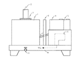
図1は、この発明の実施形態である廃油ストーブの外観を示す正面図である。図において、左側部分が燃焼室1である。燃焼室1の背部には煙突2が設けられている。3は、燃焼室の上部を覆う蓋である。また右側部分には、廃油タンク4および灯油タンク5が設けられている。燃焼室1と廃油タンク4との間には遮熱板6が設けられている。7は廃油タンク4または灯油タンク5の燃料を燃焼室1に供給する経路となる燃料供給路である。8は、燃焼室で燃焼されなかった燃料を一時的に溜める流出防止タンクである。9は、流出防止タンク8に溜まった燃料を排出するドレンである。また、廃油タンク4および灯油タンク5の下側の室には、ファン10(図中破線で示している。)が設けられている。このファン10は、流出防止タンク8に空気を吹き出す。ファン10が流出防止タンク8に吹き出した空気は燃焼室1に送られる。なお、ファン10は廃油を完全燃焼させるのに十分な空気を燃焼室1に供給することができる。
【0012】
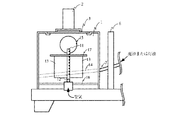
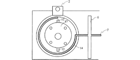
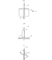
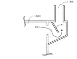
図2は、燃焼室内部の構造を示す正面断面図であり、図3は燃焼室内部の構造を示す上面断面図である。燃焼室1の略中央には表面に多数の孔を有するパイプ11を燃焼室1内の底板16に対して着脱自在に設けている。なお、パイプ11に設けられている多数の孔は、後述するようにこの孔から吹き出された空気を空気流制御板13によって燃焼室1内で渦状に対流させるように所定間隔で縦列に設けている。また、パイプ11には、図4に示すように下端部にパイプ12が水平方向に取り付けられており、略中央に半円状の空気流制御板13が取り付けられている。なお、図4(B)は図4(A)におけるA方向の矢視図であり、図4(C)は図4(A)におけるB方向の矢視図である。また、パイプ12も表面に多数の孔を有している。
【0013】
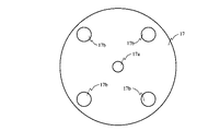
また、燃焼室1内の壁面に沿って供給される燃料を流通させる流通路14を形成している。この流通路14と前記燃料供給路7とはつながっている。15は排気口であり、煙突2につながっている。さらに、パイプ11の上部には図5に示す安定板17が取り付けられている。安定板17には、略中央にパイプ11の外径と同じ開口部17aを設けており、底板16に取り付けられたパイプ11の上端をこの開口部17aに通し、空気流制御板13の上端部に乗せている。また、安定板17には、図示するように4つの開口部17bを設けており、この開口部17aを設けたことによって燃焼室1内から煙突2への排気が効率よく行われる。
【0014】
パイプ11は下端部を開口しており、ファン10から吹き出された空気が流出防止タンク8を通って内部に吹き込まれる。また、パイプ11の上端部は閉じられている。パイプ11内部に吹き込まれた空気は、パイプ12内部にも入る。そして、これらの空気はパイプ11、12の表面に設けられた多数の孔から吹き出される。ここで、パイプ11に設けられている孔から吹き出された空気は、半円状の2枚の空気流制御板13によって燃焼室1内部で渦状に対流させられる。また、パイプ12は、ななめ下方に向けて空気を吹き出すように孔を形成しており、パイプ12から吹き出された空気によって燃焼室1内における空気の上下方向の対流を促進させている。さらに、煙突2の内部には図6に示すように仕切り板20を設けており、燃焼時にはこの仕切り板20が熱を持って2次燃焼を助ける働きをする。
【0015】
次に、この実施形態の廃油ストーブの操作方法について説明する。
まず、廃油ストーブの点火操作について説明する。最初に、燃焼室1に灯油タンク5内の灯油の供給を行う。この実施形態では、灯油タンク5に供給バルブを設けており、操作者がこのバルブを開けることによって燃焼室1への灯油の供給が開始される。なお、所定のスイッチ操作によって灯油タンク5内の灯油の供給が開始されるように構成してもよい。このとき、廃油タンク4内の廃油は燃焼室1に供給しない。灯油タンク5内の灯油は、燃料供給路7を通って燃焼室1に入り、流通路14を流れ、底板16の上に溜まる。底板16の上に一定量の灯油が溜まると、操作者は蓋3を開けて底板16の上に溜まっている灯油にマッチ等で直接点火し、蓋3を閉める。そして、操作者は図示していないファンスイッチを操作してファン10の運転を開始させる。これにより、ファン10から空気が吹き出される。この空気は流出防止タンク8を通って燃焼室1に設けられているパイプ11に吹き込まれる。燃焼室1内では、パイプ11の孔から吹き出された空気が上述したように空気流制御板13によって渦状に対流させられる。また、燃焼室1内ではパイプ12の表面に設けられた孔から吹き出された空気によって上下方向の対流も促進される。以上の操作によって、点火操作を完了する。なお、燃焼室2内部に公知の点火装置を設けておき、スイッチ操作によって灯油への点火が行われるように構成してもよい。
【0016】
このように、点火時には燃焼室1に灯油を燃料として供給し、底板16の上に溜まった灯油に直接点火するようにしているので、確実、且つ、簡単に点火が行える。
【0017】
燃焼室1内は、灯油の燃焼によって温度が上昇する。そして、温度が所定の温度を越えると、燃焼室1内に設けた流通路14を流れる灯油が気化する。また、上述のように燃焼室1内では空気を渦状に対流させてているので、この気化した灯油と空気とが適当に混合され、燃焼が効率よく行われる。この後、燃焼室1に廃油の供給を開始する操作を行うとともに、燃焼室1への灯油の供給を停止する操作を行う。この実施形態では、操作者自信が灯油から廃油への切り替え時機を判断し、廃油の供給バルブを開けるとともに、灯油の供給バルブを閉める。なお、灯油への点火後の経過時間が所定時間に達したときに、自動的に燃焼室1への燃料の供給を灯油から廃油に切り替えるように構成してもよいし、また、燃焼室1内の温度を測定するセンサを設け、燃焼室1内の温度が所定温度未満のときには灯油タンク5から灯油を供給し、所定温度以上のときには灯油の供給を停止して廃油タンク4から廃油を供給するように構成してもよい。
【0018】
燃焼室1に供給される廃油も上記した灯油の場合と同様に流通路14を流れ、燃焼室1内で気化する。また、上述したように、燃焼室1内ではパイプ11、12の表面に設けられている孔から吹き出された空気が渦状に対流しているので、燃焼室1内において気化した廃油と空気が適当に混合されることになる。このため、燃焼室1内おける廃油の燃焼効率を向上させることができ、よって、廃油を略完全に燃焼させられる。
【0019】
さらに、空気流制御板13は空気を渦状に対流させるだけでなく、燃焼室1内における燃料(灯油または廃油)の燃焼により熱を持って、燃焼室1内における燃料の燃焼を助ける働きをする。また、安定板17は、燃焼室1内における炎を安定させることで、燃焼室1における廃油の燃焼を安定させるとともに、熱が伝わるため空気流制御板13と同様に燃焼を助ける働きもする。また、図6に示す煙突2内部に設けた仕切り板20にも燃焼室1内における燃焼による熱が伝わる。ここで、図6中に矢印で示すように燃焼室1からの排気は流れる。この排気の中には燃焼室1内で完全に燃焼されなかった気化した廃油が含まれていると、熱を持った仕切り板20によって2次燃焼をおこさせることができる。したがって、煙突2から煙りがほとんどでることがない。
【0020】
このように、本実施形態の廃油ストーブでは、廃油を気化させて効率よく燃焼させることができるので、燃焼による煙がほとんど出ることがない。また、燃焼室1と廃油タンク4および灯油タンク5との間には、遮熱板6を設けているので、燃焼室1内における灯油または廃油の燃焼による熱が廃油タンク4および灯油タンク5に伝わらないので、火災が発生することもない。さらに、燃焼室1内で、灯油または廃油を燃焼させているときには、ファン10から吹き出された空気がパイプ12の孔から吹き出されるため、燃焼室1内の燃焼による炎が流出防止タンク8内に入ることもなく、安全である。したがって、本実施形態の廃油ストーブは十分な安全性も備えているといえる。
【0021】
つぎに、消火時に操作について説明する。消火は、燃焼室1への燃料の供給を停止することによって行う。この実施形態では、燃焼室1に廃油を供給するバルブおよび灯油を供給するバルブの両方を閉じることによって行う。このとき、ファン10の運転は停止させない。これは、バルブを閉めたことによって燃料の供給を停止しても、底板16の上や、燃料供給路7および流通路14に残っているからである。燃料供給路7および流通路14に残っていた燃料も燃焼し燃焼室1内の燃料が無くなると、燃焼室1における燃焼が終わる(消火される)。操作者は、燃焼室1内の燃焼が終わったことを確認した後に、図示していないファンスイッチを操作してファン10の運転を停止させる。
【0022】
以上のように、本実施形態の廃油ストーブでは、燃焼室1内に設けたパイプ11、12と空気流制御板13によって、燃焼室1内でファン10によって供給した空気を渦状に対流させるとともに、燃焼室1内に供給した燃料を気化させるため、燃焼室1内において空気と燃料である廃油とを適当に混合することができる。これによって、燃焼室1内における燃焼効率を向上させることができ、エンジンオイルやてんぷら油等の比較的燃焼させにくい廃油を燃料として使用しても、ほぼ完全に燃焼させることができるので、ほとんど煙りが出ない。また、このように廃油を燃料としたため、燃料費も低減されることになる。さらに、燃焼室の壁面に沿って流通路14を設けるという簡単な構成によって、燃焼室1内に供給した廃油を気化させるようにしたため、廃油の中に金属片等の不純物が混入していても、何ら問題なく廃油を気化させることができる。さらに、パイプ11、12は、燃焼室1内において着脱自在に設けているので、パイプ11、12を燃焼室1から取り外すことにより、パイプ11、12の孔の詰まり等の掃除も簡単に行える。また、燃焼室1内において供給された燃料は略完全に燃焼されるので、ほとんど煙突2から煙りがでることがないので、煙突2はほとんど掃除する必要がない。また、気化させて燃焼させた廃油に含まれていた固形物は、流通路14等に溜まるが、この掃除も蓋3を開けて簡単に行える。また、燃焼中でないときに誤ってバルブを開放しても、底板16の上に所定量以上(液面がパイプ12の孔の位置)の灯油や廃油が溜まることはない。これは、ファン10が停止していればパイプ12の表面に設けた孔からこの溜まった燃料が流出防止タンク8に流れ込むからである。
【0023】
なお、上記した実施形態の廃油ストーブで実際に廃油を燃焼させたときに、煙りはほとんど見られなかった。また、同時に一酸化炭素および炭化水素を測定したが共に関知できなかった。したがって、燃焼室1に供給した廃油はほぼ完全に燃焼されていると言える。
【0024】
また、図7に示すように燃焼室1の外側の周囲に螺旋状の空気流通路31を設け、一方の開口部31aに図示していないファンで空気を入れる構造としてもよい。このようにすれば、一方の開口部31aから吹き込まれた空気は、燃焼室1の外側の周囲を螺旋状に流れ、他方の開口部31bから吹き出される。ところで、空気流通路31を流れている間に空気は燃焼室1内での廃油等の燃焼による熱を受けて温風となる。すなわち、他方の開口部31bからは温風が吹き出されるのである。したがって、廃油を燃料とする温風装置を構成することもできる。
【0025】
【発明の効果】
以上のように、この発明によれば、燃焼室内において、空気を渦状に対流させるようにしたことにより、気化された廃油と空気とを適当に混合することができ、廃油を略完全に燃焼させることができる。これにより、煙りがほとんど出ない現実的に使用可能な廃油ストーブを実現できる。また、ファンが停止していれば、燃焼室に第2のパイプの表面の孔よりも上まで廃油が溜まることがないので、燃焼中でないときに誤って廃油を燃焼室に供給した場合であっても、第2のパイプの孔の位置よりも上まで燃料が溜まることがない。
【0026】
また、燃焼室の壁面に沿って廃油を流すという簡単な構成で燃料である廃油を気化させるようにしたため、鉄片等の固形物を含んだ廃油であっても何ら問題なく燃料として使用することができる。
【図面の簡単な説明】
【図1】この発明の実施形態である廃油ストーブの外観を示す正面図である。
【図2】同実施形態の廃油ストーブにおける燃焼室の正面断面図である。
【図3】同実施形態の廃油ストーブにおける燃焼室の上面断面図である。
【図4】同実施形態の廃油ストーブにおけるパイプの構成を示す図である。
【図5】同実施形態の安定板の構成を示す図である。
【図6】同実施形態の廃油ストーブにおける煙突の内部断面図である。
【図7】他の実施形態である廃油ストーブの外観を示す正面図である。
【符号の説明】
1−燃焼室
4−廃油タンク
7−燃料供給路
10−ファン
11−パイプ
13−空気流制御板
14−流通路[0001]
BACKGROUND OF THE INVENTION
The present invention relates to a waste oil stove that uses waste oil such as engine oil and tempura oil as fuel.
[0002]
[Prior art]
Conventionally, a kerosene stove has been used as a heating device. Recently, a stove has been proposed in which kerosene is supplied to the combustion chamber in the form of a mist and burned. Such a kerosene stove has the merit that the burning efficiency of kerosene as fuel is better and the amount of smoke emitted at the time of combustion is smaller than the kerosene stove that ignites the core impregnated with kerosene.
[0003]
[Problems to be solved by the invention]
Recently, the destruction of the natural environment due to the dumping of waste oil such as engine oil and tempura oil has become a problem. Accordingly, waste oil stoves using these waste oils as fuels have been proposed. Furthermore, not only can the problem of destruction of the natural environment be solved, but there is also a merit that the fuel cost becomes extremely low by using waste oil as fuel.
[0004]
However, there is a problem that waste oil is harder to burn than kerosene. And if the waste oil which is a fuel cannot be burned almost completely, there will be much smoke exhausted and it cannot be practically used as a heating device. In addition, in order to adopt the configuration that is applied to the conventional kerosene stove and supplies the fuel to the combustion chamber in the form of a mist, solids that are impurities contained in the waste oil (for example, the engine) Oil often contains metallic materials such as iron pieces.) Must be removed. This is because, when waste oil containing such solids is used as fuel, the solids accumulate in a mechanism for making the waste oil mist, and the mechanism is damaged by the accumulated solids. This is because problems arise.
[0005]
An object of the present invention is to provide a practical waste oil stove that emits almost no smoke by evaporating liquid waste oil supplied in a combustion chamber and convection of air supplied to the combustion chamber to efficiently burn the waste oil. There is.
[0006]
Another object of the present invention is to provide a waste oil stove that can use waste oil containing impurities such as iron pieces as fuel without any problems.
[0007]
[Means for Solving the Problems]
This invention is a waste oil stove that supplies waste oil in a waste oil tank to a combustion chamber, vaporizes and burns the waste oil supplied in the combustion chamber,
A spill prevention tank provided under the combustion chamber and storing fuel that has not been burned in the combustion chamber; and a fan that blows out air to the spill prevention tank,
The combustion chamber has a plurality of holes on the surface, is vertically attached to a bottom plate that partitions the spill prevention tank and the combustion chamber, and a first pipe into which air blown into the spill prevention tank is blown by the fan A second pipe having a large number of holes on the surface and horizontally attached to a lower end portion of the first pipe, into which air blown into the first pipe enters, and the first pipe And an air flow control plate having a semicircular cross section in the horizontal direction is provided .
[0008]
In this configuration, the air blown into the outflow prevention tank by the fan is blown into the first pipe and the second pipe, and a large number of holes provided on the surfaces of the first pipe and the second pipe. Is blown out. A semicircular air flow control plate convects the air blown from the numerous holes in a vortex in the combustion chamber. Thus, since air is convected in the combustion chamber, the waste oil vaporized in the combustion chamber and the air are efficiently mixed, so that the waste oil can be burned almost completely and almost no smoke is emitted. In addition, if the fan is stopped, the waste oil does not accumulate in the combustion chamber beyond the hole on the surface of the second pipe, so that the waste oil was accidentally supplied to the combustion chamber when not in combustion. However, the fuel does not collect up to the position above the hole of the second pipe.
[0009]
Further, the present invention is characterized in that a waste oil flow passage is provided in the combustion chamber for flowing the waste oil supplied from the waste oil tank along the wall surface of the combustion chamber.
[0010]
In this configuration, the waste oil supplied into the combustion chamber flows along the wall surface of the combustion chamber. Here, since the combustion chamber becomes high temperature during combustion, the waste oil flowing through the waste oil flow passage is vaporized. That is, the waste oil can be vaporized by a simple configuration of a waste oil flow passage for flowing the waste oil along the wall surface of the combustion chamber. Here, even if the waste oil, which is fuel, contains solids such as iron pieces, the solids only accumulate in the waste oil flow passage, etc., so the solid matter collected in the waste oil flow passage etc. is cleaned at an appropriate timing. By simply performing (taking out) the maintenance, there is no problem that the main body breaks down due to the solid matter contained in the waste oil.
[0011]
DETAILED DESCRIPTION OF THE INVENTION
FIG. 1 is a front view showing an appearance of a waste oil stove according to an embodiment of the present invention. In the figure, the left side is the combustion chamber 1. A
[0012]
FIG. 2 is a front sectional view showing the structure inside the combustion chamber, and FIG. 3 is a top sectional view showing the structure inside the combustion chamber. A
[0013]
In addition, a
[0014]
The
[0015]
Next, the operation method of the waste oil stove of this embodiment will be described.
First, the ignition operation of the waste oil stove will be described. First, kerosene in the kerosene tank 5 is supplied to the combustion chamber 1. In this embodiment, the kerosene tank 5 is provided with a supply valve, and when the operator opens the valve, the supply of kerosene to the combustion chamber 1 is started. In addition, you may comprise so that supply of the kerosene in the kerosene tank 5 may be started by predetermined | prescribed switch operation. At this time, the waste oil in the
[0016]
In this way, kerosene is supplied as fuel to the combustion chamber 1 at the time of ignition, and the kerosene accumulated on the
[0017]
The temperature in the combustion chamber 1 rises due to the burning of kerosene. And if temperature exceeds predetermined temperature, the kerosene which flows through the
[0018]
The waste oil supplied to the combustion chamber 1 also flows through the
[0019]
Further, the air
[0020]
Thus, in the waste oil stove of this embodiment, since waste oil can be vaporized and burned efficiently, there is almost no smoke due to combustion. In addition, since a
[0021]
Next, the operation during fire extinguishing will be described. Fire extinguishing is performed by stopping the supply of fuel to the combustion chamber 1. In this embodiment, this is done by closing both the valve for supplying waste oil to the combustion chamber 1 and the valve for supplying kerosene. At this time, the operation of the
[0022]
As described above, in the waste oil stove of the present embodiment, the
[0023]
In addition, smoke was hardly seen when waste oil was actually burned with the waste oil stove of the above-described embodiment. At the same time, carbon monoxide and hydrocarbons were measured. Therefore, it can be said that the waste oil supplied to the combustion chamber 1 is almost completely burned.
[0024]
Further, as shown in FIG. 7, a spiral
[0025]
【The invention's effect】
As described above, according to the present invention, since the air is convected in the combustion chamber, the vaporized waste oil and air can be appropriately mixed, and the waste oil is burned almost completely. be able to. As a result, a practically usable waste oil stove that hardly emits smoke can be realized. In addition, if the fan is stopped, the waste oil does not accumulate in the combustion chamber beyond the hole on the surface of the second pipe, so that the waste oil was accidentally supplied to the combustion chamber when not in combustion. However, the fuel does not collect up to the position above the hole of the second pipe.
[0026]
In addition, since the waste oil, which is a fuel, is vaporized with a simple configuration of flowing the waste oil along the wall surface of the combustion chamber, even waste oil containing solids such as iron pieces can be used as fuel without any problems. it can.
[Brief description of the drawings]
FIG. 1 is a front view showing an appearance of a waste oil stove according to an embodiment of the present invention.
FIG. 2 is a front sectional view of a combustion chamber in the waste oil stove of the same embodiment.
FIG. 3 is a top cross-sectional view of a combustion chamber in the waste oil stove of the same embodiment.
FIG. 4 is a view showing a configuration of a pipe in the waste oil stove of the same embodiment.
FIG. 5 is a view showing a configuration of a stabilizer according to the embodiment.
FIG. 6 is an internal cross-sectional view of a chimney in the waste oil stove of the same embodiment.
FIG. 7 is a front view showing an appearance of a waste oil stove according to another embodiment.
[Explanation of symbols]
1-Combustion chamber 4-Waste oil tank 7-Fuel supply path 10-Fan 11-Pipe 13-Air flow control plate 14-Flow path
Claims (2)
前記燃焼室の下に設けられ、前記燃焼室で燃焼されなかった燃料を溜める流出防止タンクと、この流出防止タンクに空気を吹き出すファンと、を有するとともに、
前記燃焼室に、表面に多数の孔を有し、前記流出防止タンクと燃焼室とを仕切る底板に垂直に取り付けられ、前記ファンが前記流出防止タンクに吹き出した空気が吹き込まれる第1のパイプと、表面に多数の孔を有し、前記第1のパイプの下端部に水平方向に取り付けられ、前記第1のパイプに吹き込まれた空気が内部に入り込む第2のパイプと、前記第1のパイプの表面に取り付けられ、水平方向の断面が半円状である空気流制御板と、が設けられていることを特徴とする廃油ストーブ。A waste oil stove that supplies waste oil in a waste oil tank to a combustion chamber, vaporizes and burns the waste oil supplied in the combustion chamber,
A spill prevention tank provided under the combustion chamber and storing fuel that has not been burned in the combustion chamber; and a fan that blows out air to the spill prevention tank,
A first pipe having a number of holes on the surface thereof, vertically attached to a bottom plate partitioning the spill prevention tank and the combustion chamber, wherein the fan blows air blown into the spill prevention tank; A second pipe having a large number of holes on the surface and horizontally attached to a lower end portion of the first pipe, into which air blown into the first pipe enters, and the first pipe A waste oil stove provided with an air flow control plate attached to the surface of the air flow control plate and having a semicircular horizontal cross section .
Priority Applications (1)
| Application Number | Priority Date | Filing Date | Title |
|---|---|---|---|
| JP07707897A JP3649849B2 (en) | 1997-03-28 | 1997-03-28 | Waste oil stove |
Applications Claiming Priority (1)
| Application Number | Priority Date | Filing Date | Title |
|---|---|---|---|
| JP07707897A JP3649849B2 (en) | 1997-03-28 | 1997-03-28 | Waste oil stove |
Publications (2)
| Publication Number | Publication Date |
|---|---|
| JPH10267283A JPH10267283A (en) | 1998-10-09 |
| JP3649849B2 true JP3649849B2 (en) | 2005-05-18 |
Family
ID=13623756
Family Applications (1)
| Application Number | Title | Priority Date | Filing Date |
|---|---|---|---|
| JP07707897A Expired - Fee Related JP3649849B2 (en) | 1997-03-28 | 1997-03-28 | Waste oil stove |
Country Status (1)
| Country | Link |
|---|---|
| JP (1) | JP3649849B2 (en) |
-
1997
- 1997-03-28 JP JP07707897A patent/JP3649849B2/en not_active Expired - Fee Related
Also Published As
| Publication number | Publication date |
|---|---|
| JPH10267283A (en) | 1998-10-09 |
Similar Documents
| Publication | Publication Date | Title |
|---|---|---|
| JP2010075823A (en) | Apparatus for decomposition treatment of organic matter | |
| KR102631474B1 (en) | Charcoal ignition apparatus | |
| KR101312963B1 (en) | Wood combustor | |
| JP3649849B2 (en) | Waste oil stove | |
| JP2011133118A (en) | Waste oil combustion device | |
| GB2091414A (en) | Solid fuel combustion appliances | |
| KR200400023Y1 (en) | Wood boiler | |
| JP2000257834A (en) | Stove for burning waste oil by swirl combustion | |
| JP5930249B1 (en) | Waste oil stove | |
| JPH094820A (en) | Liquid fuel combustion device | |
| JP2005326076A (en) | Waste incinerator | |
| US4480987A (en) | Combustion apparatus for liquid fuels | |
| JP3153223U (en) | Stove | |
| US1862691A (en) | Oil burner | |
| KR200249584Y1 (en) | multi-burning type fireplace | |
| JPH037707Y2 (en) | ||
| JP2005315543A (en) | Waste oil stove | |
| EP1112464B1 (en) | Water heater for central heating | |
| JPS6026268Y2 (en) | combustion furnace | |
| KR100846963B1 (en) | Automatic multi-purpose boiler | |
| US2465166A (en) | Heater for tobacco barns | |
| JP2000220889A (en) | Hot-water boiler | |
| JPS6334361B2 (en) | ||
| JPH06109214A (en) | Combustion apparatus | |
| US1393994A (en) | Stephen ivan fekete |
Legal Events
| Date | Code | Title | Description |
|---|---|---|---|
| A131 | Notification of reasons for refusal |
Free format text: JAPANESE INTERMEDIATE CODE: A131 Effective date: 20041005 |
|
| A521 | Written amendment |
Free format text: JAPANESE INTERMEDIATE CODE: A523 Effective date: 20041206 |
|
| TRDD | Decision of grant or rejection written | ||
| A01 | Written decision to grant a patent or to grant a registration (utility model) |
Free format text: JAPANESE INTERMEDIATE CODE: A01 Effective date: 20050208 |
|
| A61 | First payment of annual fees (during grant procedure) |
Free format text: JAPANESE INTERMEDIATE CODE: A61 Effective date: 20050216 |
|
| R150 | Certificate of patent or registration of utility model |
Free format text: JAPANESE INTERMEDIATE CODE: R150 |
|
| FPAY | Renewal fee payment (event date is renewal date of database) |
Free format text: PAYMENT UNTIL: 20100225 Year of fee payment: 5 |
|
| FPAY | Renewal fee payment (event date is renewal date of database) |
Free format text: PAYMENT UNTIL: 20100225 Year of fee payment: 5 |
|
| FPAY | Renewal fee payment (event date is renewal date of database) |
Free format text: PAYMENT UNTIL: 20110225 Year of fee payment: 6 |
|
| LAPS | Cancellation because of no payment of annual fees |