JP3649836B2 - Method for improving resolution of magnetic field deflection mass spectrometer for leak detection - Google Patents
Method for improving resolution of magnetic field deflection mass spectrometer for leak detection Download PDFInfo
- Publication number
- JP3649836B2 JP3649836B2 JP01048597A JP1048597A JP3649836B2 JP 3649836 B2 JP3649836 B2 JP 3649836B2 JP 01048597 A JP01048597 A JP 01048597A JP 1048597 A JP1048597 A JP 1048597A JP 3649836 B2 JP3649836 B2 JP 3649836B2
- Authority
- JP
- Japan
- Prior art keywords
- magnetic field
- ions
- ion
- leak detection
- gas
- Prior art date
- Legal status (The legal status is an assumption and is not a legal conclusion. Google has not performed a legal analysis and makes no representation as to the accuracy of the status listed.)
- Expired - Lifetime
Links
- 238000001514 detection method Methods 0.000 title claims description 38
- 238000000034 method Methods 0.000 title claims description 9
- 150000002500 ions Chemical class 0.000 claims description 91
- 239000007789 gas Substances 0.000 claims description 47
- XKRFYHLGVUSROY-UHFFFAOYSA-N Argon Chemical compound [Ar] XKRFYHLGVUSROY-UHFFFAOYSA-N 0.000 claims description 38
- 238000004458 analytical method Methods 0.000 claims description 24
- 239000000523 sample Substances 0.000 claims description 22
- 239000001307 helium Substances 0.000 claims description 21
- 229910052734 helium Inorganic materials 0.000 claims description 21
- SWQJXJOGLNCZEY-UHFFFAOYSA-N helium atom Chemical compound [He] SWQJXJOGLNCZEY-UHFFFAOYSA-N 0.000 claims description 20
- 229910052786 argon Inorganic materials 0.000 claims description 19
- 238000000605 extraction Methods 0.000 claims description 16
- IJGRMHOSHXDMSA-UHFFFAOYSA-N Atomic nitrogen Chemical compound N#N IJGRMHOSHXDMSA-UHFFFAOYSA-N 0.000 claims description 10
- CURLTUGMZLYLDI-UHFFFAOYSA-N Carbon dioxide Chemical compound O=C=O CURLTUGMZLYLDI-UHFFFAOYSA-N 0.000 claims description 10
- QVGXLLKOCUKJST-UHFFFAOYSA-N atomic oxygen Chemical compound [O] QVGXLLKOCUKJST-UHFFFAOYSA-N 0.000 claims description 5
- 239000001569 carbon dioxide Substances 0.000 claims description 5
- 229910002092 carbon dioxide Inorganic materials 0.000 claims description 5
- 239000001301 oxygen Substances 0.000 claims description 5
- 229910052760 oxygen Inorganic materials 0.000 claims description 5
- 229910052757 nitrogen Inorganic materials 0.000 claims description 3
- 238000001819 mass spectrum Methods 0.000 description 12
- 230000001133 acceleration Effects 0.000 description 11
- 238000010586 diagram Methods 0.000 description 10
- 238000005259 measurement Methods 0.000 description 3
- UGFAIRIUMAVXCW-UHFFFAOYSA-N Carbon monoxide Chemical compound [O+]#[C-] UGFAIRIUMAVXCW-UHFFFAOYSA-N 0.000 description 2
- YCKRFDGAMUMZLT-UHFFFAOYSA-N Fluorine atom Chemical compound [F] YCKRFDGAMUMZLT-UHFFFAOYSA-N 0.000 description 2
- 229910002091 carbon monoxide Inorganic materials 0.000 description 2
- 239000006185 dispersion Substances 0.000 description 2
- 230000000694 effects Effects 0.000 description 2
- 229910052731 fluorine Inorganic materials 0.000 description 2
- 239000011737 fluorine Substances 0.000 description 2
- MWUXSHHQAYIFBG-UHFFFAOYSA-N nitrogen oxide Inorganic materials O=[N] MWUXSHHQAYIFBG-UHFFFAOYSA-N 0.000 description 2
- 238000001228 spectrum Methods 0.000 description 2
- 238000004364 calculation method Methods 0.000 description 1
- 238000002474 experimental method Methods 0.000 description 1
- 230000004907 flux Effects 0.000 description 1
- -1 helium ions Chemical class 0.000 description 1
- 238000004519 manufacturing process Methods 0.000 description 1
- 238000004949 mass spectrometry Methods 0.000 description 1
- 238000000691 measurement method Methods 0.000 description 1
- 239000000203 mixture Substances 0.000 description 1
- 230000035945 sensitivity Effects 0.000 description 1
- 239000007921 spray Substances 0.000 description 1
Images

Landscapes
- Examining Or Testing Airtightness (AREA)
- Electron Tubes For Measurement (AREA)
- Other Investigation Or Analysis Of Materials By Electrical Means (AREA)
Description
【0001】
【発明の属する技術分野】
本発明は、ヘリウム等のプローブガスを中空の漏洩検知対象物の周囲に吹き付け、該対象物の漏洩部を検知するプローブ法に使用される漏洩検知装置の磁場偏向型質量分析管の分解能を向上させる方法に関する。
【0002】
【従来の技術】
従来、この種の漏洩検知装置に使用される磁場偏向型質量分析管は、内部が真空に排気された管内に、図1に示すようにイオン化室aと磁場偏向型分析器b及び検出室cとを設けて構成され、該分析器bとして扇形の永久磁石dが用いられる。該イオン化室a内にはグリッド(エレクトロンコレクター)eとフィラメントf及びイオン引出電極gが設けられ、該検出室cにはコレクタースリットhを介してイオンコレクターiが設けられる。また該フィラメントfはフィラメント電源jとイオン加速電源kに接続され、該フィラメントf及びイオン引出電極gには電子加速電源lが接続される。nはイオン電流測定器である。
【0003】
永久磁石を用いた該分析器bには、代表的なもので60度偏向、90度偏向、180度偏向等があるが、いずれも
r=(1.44×10⁻⁴√Mu×V)/B…式1
という基本的な式により質量分離するのが原理である。ここで、r:回転半径、Mu:質量数、B:磁束密度である。
【0004】
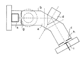
60度偏向型の該分析管bの具体的構成の1例は図2に示す如くであり、気密の管の中間に永久磁石dを配置し、該管の一端にイオン化室aを設け、他端に検出室cが設けられる。該イオン化室aと永久磁石dのとの間の該管の側壁に漏洩検知対象物の中空内部及び真空ポンプへ繋がる測定管pの端部が接続される。該測定管pには、例えば図3に示すようにターボ分子ポンプやメカニカルブースターポンプ等の真空ポンプqで排気されるチャンバーrが接続され、漏洩検知対象物sに漏洩部が存在したとき、該対象物sに吹きかけたプローブガスがその内部から該分析管b内へ拡散して漏洩の存在が確認される。即ち、真空の該分析管b内では該フィラメントfから放出された熱電子が電子加速電源lによって調整された速度でグリッドe内へ飛翔し、そこに存在する該対象物sから漏れたプローブガスを電子衝撃してこれをイオン化し、そのイオンは静電加速系やイオン加速電源kの電圧の力を受けてイオン引出電極gより引き出される。そしてイオン加速電源kによる加速電圧とグリッド電圧を調整すると、1式のBが一定であるから質量数Muにより回転半径が異なることを利用してある特定のイオンをイオンコレクターiに到達させることができる。イオン加速電源kの電圧を変化させると、イオンコレクターiに到達するイオンの種類が変化するから、該分析管b中のガスの組成を検出することもできる。グリッド電圧はプローブガスを集めることができる電圧に調整される。
【0005】
【発明が解決しようとする課題】
従来の漏洩検知装置では、プローブガスとしてヘリウムガスを使用するのが一般的であるが、ヘリウムガスは価格が高いという欠点がある。また、簡便な漏洩検知装置の磁場偏向型質量分析管ではヘリウムスペクトルのみが分離できればよいのでその分解能が4〜8程度に設計されており、ヘリウムよりも質量数の大きい気体のスペクトルを分離できるようにするには、該分析管の感度を大幅に落として分解能を向上させるか、大型で高価な磁場偏向型質量分析管を使用したり、或いは漏洩検知用よりもはるかに高価な四重極質量分析管を使用しなければならず、装置価格の上昇を嫌って結局はヘリウムガスを使用することで漏洩検知の経済性を求めることが多くなっている。尚、漏洩検知の方法として、プローブガスとしてヘリウムガス以外の例えばアルゴンガスを使用することは、すでに特開昭54−50390号公報に開示されている。
【0006】
本発明は、簡便な構成で比較的小型の漏洩検知用の磁場偏向型質量分析管の分解能を向上させ、各種のプローブガスを使用して漏洩検知を安価に行える方法を提案することを目的とするものである。
【0007】
【課題を解決するための手段】
本発明では、内部を真空に排気した中空の漏洩検知対象物の周囲に、ヘリウムガス、アルゴンガス等のプローブガスを吹き付け、該対象物の漏洩部からその内部へ侵入する該プローブガスのガス原子や分子を電子衝撃によりイオン化すると共にイオン引出電極のスリットを介してイオンを引き出すイオン化室と、該イオン化室から引き出されたイオンのうちの特定のイオンを選別する永久磁石を用いた磁場偏向型分析器と、該特定のイオンの量をコレクタースリットを介して入射するイオンコレクターにより検出する検出室を備えた質量分析管に於いて、該磁場偏向型分析器を構成する永久磁石のイオン入射側の有効磁場面に対し該イオン化室から引き出されたイオンの中心軸を斜めに設定すると共に該イオン引出電極のスリット幅と該コレクタースリットの幅の少なくとも一方を狭めることにより、上記の目的を達成するようにした。該磁場偏向型分析器を、該分析器へ入射するイオンの中心軸に対して該分析器から出射するイオンの中心軸を90度偏向させる永久磁石で構成し、該永久磁石の有効磁場面に対して20度斜めにイオンを入射させることが好ましく、プローブガスには、ヘリウム、アルゴン、二酸化炭素、窒素、酸素が使用でき、通常は安価なアルゴンガスを使用して漏洩検知を行い、微少な漏洩を検知するときにヘリウムガスに交換して行える。
【0008】
【発明の実施の形態】
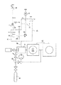
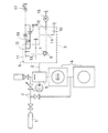
本発明の実施の形態を図4に基づき説明すると、同図に於いて符号1は中空の漏洩検知対象物、2は一端が該対象物1の内部に連なり他端が磁場偏向型質量分析管3に接続された測定管、4は該測定管2及び該分析管3内を真空に排気するターボ分子ポンプとメカニカルブースターポンプで構成された排気系、5は該測定管2の中間に設けたチャンバーを示す。該磁場偏向型質量分析管3は、漏洩検知用の簡易で小型のもので、イオン化室6と永久磁石7から成る磁場偏向型分析器8を設けたイオン偏向部9及び検出室10で構成され、該イオン化室6にはグリッド(エレクトロンコレクター)11、フィラメント12及びスリット状のイオン引出電極13を設け、該検出室10には該分析器8で選別されたイオンを通過させるコレクタースリット14とイオン電流検出器15に接続されたイオンコレクター16が設けられる。
【0009】
こうした構成は図3に示した従来の漏洩検知装置の構成と特に変わりがなく、該グリッド11にイオン加速電源17を接続すると共にフィラメント12との間に電子加速電源18を接続し、該フィラメント12にフィラメント電源19を接続する構成も従来のものと同様であり、排気系4を作動させてプローブガスを該対象物1に吹き付け、該対象物1の漏洩部からその内部へ漏れたプローブガスを該分析管3内のイオン化室6に於いてイオン化し、そのイオンを永久磁石7で偏向してイオンコレクター16に入射させて漏洩部の存在を検知することも従来のものと同様である。
【0010】
これを更に説明すると、該分析管3内へ漏れたプローブガスは電子加速電源18により加速されたフィラメント12からの熱電子と衝突してイオン化され、イオン引出電極13の電位により永久磁石7に向けて引き出され、該永久磁石7により特定の質量数のイオンのみがイオンコレクター16に入射し、イオン電流検知器に於いてイオン電流として漏れの存在が検知される。
【0011】
しかし、該分析管3の分解能は一般には4〜8程度であり、ヘリウム以外の質量数の大きなガスをプローブガスとして使用しても、質量スペクトルとして分離ができない。該分析管3の分解能Rは、通常、
R=r/(S1+S2+rα2+rΔV/V)…式2
で表される。ここでr:偏向半径、S1:イオン引出電極のスリット幅、S2:コレクタースリット幅、α:イオンの発散角、ΔV:イオンのエネルギー分散、V:イオンのエネルギーを示す。右辺分母の第3項は、イオン化室から引き出されたイオンが有限の発散角を持つことによって生じるイオンコレクターでの像の広がりを示し、第4項はイオン化室で生成されたイオンのエネルギー分散によって生じるイオンコレクターでの像の広がりを示す。
【0012】
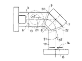
本発明は、この分解能Rを、該永久磁石7のイオン入射側の有効磁場面20に対し該イオン化室6からイオン引出電極13のスリットを介して引き出されたビーム状又は帯状イオンの中心軸21を斜めに設定すると共に該コレクタースリット14の幅を可能な範囲で狭めることにより向上させるようにしたもので、これにより、該分析管3の大きさを変えず、或いは該分析管3の代わりに高価な四重極質量分析管などを使用しなくても安価に分解能を向上させ得る。
【0013】
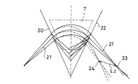
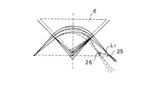
該イオン化室6から引き出されたイオンの中心軸21を、該永久磁石7の有効磁場面20の垂直軸に対して例えば20度内側へ傾斜させて設定すると、イオンはイオン出射側の有効磁場面22の垂直軸に対しても例えば20度内側から出射する傾向になり、イオンの質量数の差が大きくなると図6に示すように出射側で生じるイオンの収束点23がイオンの軌道面に対し垂直方向の収束点24へと大きな距離L2で変化し、この距離が分解能に関与することが判明した。即ち、質量数が異なる2種のイオンを有効磁場面に垂直に入射させた場合、図7に示すように収束点25、26に於いて収束し、その間の距離はL1となるが、その距離L1はこれら2種のイオンを図6のように20度斜めに入射させたときの収束点23、24間の距離L2よりも短く、L2/L1の比は、式2から計算した垂直入射の場合の分解能と実験で求めた20度斜め入射の場合の分解能との比に略一致することが分かった。
【0014】
具体的には、図5の形態の90度偏向型の磁場偏向型質量分析管3であって、式2の定数r:35mm、S1:2.5mm、S2:2mm、α:0.028rad、ΔV:7V、V:250Vである場合、有効磁場面にイオンを垂直入射させたときは式2から分解能R=7になるが、20度斜めに入射させたときは実験では分解能R=11になり、またこの場合質量数の異なるイオンを垂直入射させたときと20度斜め入射させたときの比はL2/L1=1.5で、この値は分解能の比11/7に略一致している。従って、L2/L1=Lとしてイオンを有効磁場面に斜め入射させた形態の磁場偏向型質量分析管の分解能は、
R=L・r/(S1+S2+rα2+rΔV/V)…式3
と表せることが分かった。そしてこの式3に基づきS1、S2のスリット幅の一方又は双方を可能な範囲で小さな値にすればより一層分解能を向上させ得る。
【0015】
図5の形態の分析管では、分解能が低く、質量数19のフッ素系の気体や質量数44の二酸化炭素が多い雰囲気で例えばアルゴンガスをプローブガスとして使用すると、質量数20のアルゴン2価イオンや質量数40のアルゴン1価イオンのピークがフッ素系気体や二酸化炭素のピークと接近して確認したいピークを分離できず、漏洩検知を行なえないが、有効磁場面にイオンを斜め入射させ且つイオン引出電極13のスリットの幅とコレクタースリット14のスリット幅を例えば0.5mmに狭めると、分解能Rを例えば27に向上させることができる。
【0016】
【実施例】
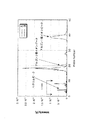
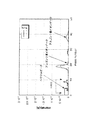
図4及び図5に示す偏向角90度の永久磁石からなる磁場偏向型分析器8を設けた漏洩検知装置であって、その分析管3の式2に関する定数をr:35mm、S1:2.5mm、S2:2mm、α:0.028rad、ΔV:7V、V:250Vとしたときの到達圧力約1×10⁻⁴Paでの質量スペクトルは、図8の曲線Aで示す如くであった。また測定管2に約10-7Pam3/s台の流量のアルゴンガスを導入し、約6×10-4Paとしたときの質量スペクトルは図8の曲線Bのようになった。尚、これらの測定中には10-9Pam3/s台の流量のヘリウムガスを流した。
【0017】
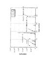
同図から質量数4のヘリウムガスのピークでの分解能はR=11であり、計算値の約1.5倍になっている。また、アルゴンの1価イオンのピーク(質量数40)、アルゴンの2価イオンのピーク(質量数20)、さらに窒素又は一酸化炭素ピーク、酸素ピーク(質量数28、32)ははっきりと分離できている。また質量数4のヘリウムイオンのピークの高さは3〜4倍の値をとる。質量数19や44が多い雰囲気であると、質量数20や40は十分に分離できない。そのためイオン引出電極13とコレクタースリット14のスリット幅をS1=S2=0.5mmに狭め、式3による計算上の分解能がR=27となるようにした。そして図8の測定時と同条件で質量スペクトルを測定した結果を図9に示す。図9の曲線Cは到達圧力約1×10-4Paでの質量スペクトル、曲線Dは測定管2に約10-7Pam3/s台の流量のアルゴンガスを導入し、約6×10-4Paとしたときの質量スペクトルである。図9から質量数4のヘリウムでの分解能はR=25でほぼ計算値と一致する。また、質量数40のアルゴンの1価イオンのピークと、質量数20のアルゴンの2価イオンのピーク、さらには窒素または一酸化炭素ピーク、酸素ピークは十分に分離されている。この場合でも二酸化炭素(質量数44)などの多い雰囲気であると質量数40は分離できないが、質量数20のピークや質量数28、32などのピークは、その他の質量数の気体の多い雰囲気でも分離できる。従って、質量数20のアルゴンの2価イオンのピーク、または窒素ピーク、酸素ピークを検出することで漏洩を検知することができる。また、図9のヘリウムピークの高さは、図2の従来の分析管による質量数4のヘリウムピークの高さと同等であった。比較のために図2の従来の分析管で有効磁場面にイオンを垂直入射させた場合の質量スペクトルを図10に示した。図10曲線Eは、図2の分析管でr:40mm、S1:2.5mm、S2:2mm、α:0.028rad、ΔV:7V、V:250Vの条件ときの到達圧力約1×10-4Paの質量スペクトルで、計算上の分解能はR=7.8である。また、図10の曲線Fは同条件でアルゴンガスを導入し圧力を約6×10-4Paにしたときの質量スペクトルである。
【0018】
尚、プローブガスとしてアルゴンを選択したときには検出できないような微小な漏洩を検出することの要望があるときは、プローブガスとしてヘリウムを選択することができ、しかもその検出限界は図2で表される従来の分析管を使用した場合と同様である。
【0019】
図9からは、通常真空中に見られる主だったピークを全て確認することができる。例えば、質量数16、17、18、28、32等である。従って、本発明の方法は、漏洩検知ばかりでなく質量数1から50までの簡易質量測定法としても利用できる。
【0020】
【発明の効果】
以上のように本発明によるときは、漏洩検知用の磁場偏向型質量分析管を構成する永久磁石の磁場偏向型分析器の有効磁場面にイオン化室から引き出されたイオンの中心軸を斜めに入射させ、更にイオン引出電極とコレクタースリットのスリット幅を可能な限り狭めて分解能を向上させるようにしたので、該有効磁場面に対するイオン入射角とスリット幅を調整するだけで簡単に分解能が向上し、従来の比較的小型で簡易な構造の分析管によりアルゴンガス等のヘリウムガス以外の安価なプローブガスを使用して漏洩検知できるから経済的であり、必要に応じてヘリウムガスを使用して微小な漏洩を検知することもでき、漏洩検知の限界も従来のものと遜色がなく、質量分析にも適用できる等の効果がある。
【図面の簡単な説明】
【図1】従来の磁場偏向型質量分析管の構成の説明図
【図2】図1の具体的構成の説明図
【図3】図1の分析管を使用した漏洩検知装置の全体の説明図
【図4】本発明の方法を適用した漏洩検知装置の全体の説明図
【図5】図4の磁場偏向型質量分析管の具体的構成の説明図
【図6】本発明の方法により2種類のイオンを永久磁石に入射させた場合の収束点の軌跡を示す線図
【図7】従来の垂直に2種類のイオンを永久磁石に入射させた場合の収束点の軌跡を示す線図
【図8】図5の磁場偏向型質量分析管の永久磁石にイオンを斜め入射させて分析した質量スペクトルの線図
【図9】図5の磁場偏向型質量分析管の永久磁石にイオンを斜め入射させると共にイオン引出電極及びコレクタースリットのスリット幅を狭めて分析した質量スペクトルの線図
【図10】図2の磁場偏向型質量分析管の永久磁石にイオンを垂直入射させて分析した質量スペクトルの線図
【符号の説明】
1 漏洩検知対象物、3 磁場偏向型質量分析管、6 イオン化室、7 永久磁石、8 磁場偏向型分析器、10 検出室、11 グリッド、12 フィラメント、13 イオン引出電極、14 コレクタースリット、16 イオンコレクター、[0001]
BACKGROUND OF THE INVENTION
The present invention improves the resolution of a magnetic field deflection type mass spectrometer tube of a leak detection apparatus used in a probe method in which a probe gas such as helium is blown around a hollow leak detection target object to detect a leak portion of the target object. It relates to the method of making it.
[0002]
[Prior art]
2. Description of the Related Art Conventionally, a magnetic field deflection type mass spectrometer tube used in this type of leakage detection apparatus has an ionization chamber a, a magnetic field deflection type analyzer b, and a detection chamber c as shown in FIG. And a fan-shaped permanent magnet d is used as the analyzer b. A grid (electron collector) e, a filament f, and an ion extraction electrode g are provided in the ionization chamber a, and an ion collector i is provided in the detection chamber c through a collector slit h. The filament f is connected to a filament power source j and an ion acceleration power source k, and an electron acceleration power source l is connected to the filament f and the ion extraction electrode g. n is an ion current measuring device.
[0003]
The analyzer b using a permanent magnet is typically a 60-degree deflection, 90-degree deflection, 180-degree deflection, etc., all of which r = (1.44 × 10⁻⁴√Mu × V) / B ...
The principle is to separate the mass by the basic formula. Here, r is the radius of rotation, Mu is the mass number, and B is the magnetic flux density.
[0004]
One example of the specific configuration of the analysis tube b of the 60-degree deflection type is as shown in FIG. 2. A permanent magnet d is disposed in the middle of the airtight tube, an ionization chamber a is provided at one end of the tube, and the like. A detection chamber c is provided at the end. The hollow portion of the leakage detection object and the end of the measurement tube p connected to the vacuum pump are connected to the side wall of the tube between the ionization chamber a and the permanent magnet d. For example, as shown in FIG. 3, a chamber r exhausted by a vacuum pump q such as a turbo molecular pump or a mechanical booster pump is connected to the measuring tube p, and when there is a leakage portion in the leakage detection object s, The probe gas sprayed on the object s diffuses from the inside into the analysis tube b, and the presence of leakage is confirmed. That is, in the vacuum analysis tube b, the probe electrons leaked from the object s present in the thermoelectrons emitted from the filament f flew into the grid e at a speed adjusted by the electron acceleration power source l. Is ionized by electron impact, and the ions are extracted from the ion extraction electrode g under the force of the voltage of the electrostatic acceleration system or the ion acceleration power source k. When the acceleration voltage and the grid voltage by the ion acceleration power source k are adjusted, a specific ion can reach the ion collector i by using the fact that the radius of rotation differs depending on the mass number Mu because B in the
[0005]
[Problems to be solved by the invention]
Conventional leak detection devices generally use helium gas as a probe gas, but helium gas has a drawback of high cost. In addition, the magnetic field deflection type mass spectrometer tube of a simple leak detection device only needs to be able to separate the helium spectrum, so the resolution is designed to be about 4 to 8, so that the spectrum of a gas having a mass number larger than that of helium can be separated. To achieve this, the sensitivity of the tube is greatly reduced to improve resolution, or a large and expensive magnetic field deflection mass spectrometer is used, or a much more expensive quadrupole mass than for leak detection. An analysis tube must be used, and the economics of leak detection are often sought by using helium gas in the end because the price of the apparatus is disliked. As a method for detecting leakage, the use of, for example, argon gas other than helium gas as the probe gas has already been disclosed in Japanese Patent Laid-Open No. 54-50390.
[0006]
An object of the present invention is to propose a method of improving the resolution of a magnetic field deflection type mass spectrometer tube for leak detection with a simple structure and a relatively small size, and capable of performing leak detection at low cost using various probe gases. To do.
[0007]
[Means for Solving the Problems]
In the present invention, a probe gas such as helium gas or argon gas is blown around a hollow leak detection object whose inside is evacuated to a vacuum, and the gas atoms of the probe gas enter the inside from the leak portion of the object Magnetic field deflection analysis using ionization chamber that ionizes ions and molecules by electron impact and draws ions through slit of ion extraction electrode, and permanent magnet that selects specific ions out of ions extracted from the ionization chamber And a mass analysis tube having a detection chamber for detecting the amount of the specific ion by an ion collector incident through a collector slit, on the ion incident side of a permanent magnet constituting the magnetic field deflection analyzer The central axis of the ions extracted from the ionization chamber is set obliquely with respect to the effective magnetic field surface, and the slit width of the ion extraction electrode and the collector By narrowing the at least one of the width of the coater slit, and to achieve the above object. The magnetic field deflection type analyzer is composed of a permanent magnet that deflects the central axis of ions emitted from the analyzer by 90 degrees with respect to the central axis of ions incident on the analyzer, and the effective magnetic field surface of the permanent magnet is It is preferable to make ions incident obliquely at an angle of 20 degrees, and helium, argon, carbon dioxide, nitrogen, and oxygen can be used as the probe gas. Usually, leak detection is performed using an inexpensive argon gas, and a minute amount It can be exchanged for helium gas when leakage is detected.
[0008]
DETAILED DESCRIPTION OF THE INVENTION
The embodiment of the present invention will be described with reference to FIG. 4. In FIG. 4,
[0009]
Such a configuration is not particularly different from the configuration of the conventional leak detection apparatus shown in FIG. 3, and an ion
[0010]
To explain this further, the probe gas leaking into the
[0011]
However, the resolution of the
R = r / (S 1 + S 2 + rα 2 + rΔV / V)
It is represented by Here, r: deflection radius, S1: slit width of the ion extraction electrode, S2: collector slit width, α: ion divergence angle, ΔV: ion energy dispersion, and V: ion energy. The third term on the right-hand side denominator shows the spread of the image at the ion collector caused by ions extracted from the ionization chamber having a finite divergence angle, and the fourth term is due to the energy dispersion of ions generated in the ionization chamber. The resulting image spread at the ion collector is shown.
[0012]
In the present invention, this resolution R is set to the
[0013]
When the
[0014]
Specifically, it is a 90-degree deflection type magnetic field deflection type
R = L · r / (S 1 + S 2 + rα 2 + rΔV / V)
I understood that it can be expressed. Further, if one or both of the slit widths of S 1 and S 2 is made as small as possible based on this
[0015]
In the analysis tube of the form of FIG. 5, when argon gas is used as a probe gas in an atmosphere having a low resolution and a mass of 19 fluorine-based gas or mass of carbon dioxide, for example, an argon divalent ion having a mass of 20 is used. The peak of argon monovalent ions with a mass number of 40 is close to the peak of fluorine-based gas or carbon dioxide, and the peak to be confirmed cannot be separated and leakage detection cannot be performed. When the slit width of the
[0016]
【Example】
4 and FIG. 5 is a leak detection apparatus provided with a magnetic field
[0017]
From the figure, the resolution at the peak of the helium gas having a mass number of 4 is R = 11, which is about 1.5 times the calculated value. In addition, the peak of argon monovalent ions (mass number 40), the peak of argon divalent ions (mass number 20), the nitrogen or carbon monoxide peak, and the oxygen peak (mass numbers 28 and 32) can be clearly separated. ing. Moreover, the height of the peak of helium ions having a mass number of 4 is 3 to 4 times higher. If the atmosphere has a large number of
[0018]
When there is a demand to detect a minute leak that cannot be detected when argon is selected as the probe gas, helium can be selected as the probe gas, and the detection limit is shown in FIG. This is the same as when a conventional analysis tube is used.
[0019]
From FIG. 9, it is possible to confirm all the main peaks normally found in vacuum. For example, the mass number is 16, 17, 18, 28, 32 or the like. Therefore, the method of the present invention can be used not only for leak detection but also as a simple mass measurement method with a mass number of 1 to 50.
[0020]
【The invention's effect】
As described above, according to the present invention, the central axis of ions extracted from the ionization chamber is obliquely incident on the effective magnetic field surface of the magnetic field deflection analyzer of the permanent magnet constituting the magnetic field deflection mass spectrometer for leak detection. Furthermore, since the resolution is improved by narrowing the slit width of the ion extraction electrode and the collector slit as much as possible, the resolution can be improved simply by adjusting the ion incident angle and the slit width with respect to the effective magnetic field surface, Since it is possible to detect leaks using an inexpensive probe gas other than helium gas such as argon gas with a conventional analysis tube having a relatively small and simple structure, it is economical. Leakage can also be detected, and the limit of leak detection is comparable to the conventional one, and there is an effect that it can be applied to mass spectrometry.
[Brief description of the drawings]
FIG. 1 is an explanatory diagram of a configuration of a conventional magnetic field deflection mass spectrometer tube. FIG. 2 is an explanatory diagram of a specific configuration of FIG. 1. FIG. 3 is an overall explanatory diagram of a leak detection apparatus using the analysis tube of FIG. FIG. 4 is an explanatory diagram of an entire leak detection apparatus to which the method of the present invention is applied. FIG. 5 is an explanatory diagram of a specific configuration of the magnetic field deflection type mass spectrometer tube of FIG. 4. FIG. Fig. 7 is a diagram showing the locus of the convergence point when two ions are incident on the permanent magnet. Fig. 7 is a diagram showing the locus of the convergence point when two types of conventional ions are incident on the permanent magnet. 8 is a diagram of a mass spectrum analyzed by obliquely injecting ions into the permanent magnet of the magnetic deflection mass spectrometer shown in FIG. 5. FIG. 9 is an oblique incidence of ions into the permanent magnet of the magnetic deflection mass spectrometer shown in FIG. And mass spectra analyzed by narrowing the slit width of the ion extraction electrode and collector slit The diagram [10] diagram of mass spectrum analysis ions into permanent magnets of the magnetic deflection
DESCRIPTION OF
Claims (3)
Priority Applications (1)
| Application Number | Priority Date | Filing Date | Title |
|---|---|---|---|
| JP01048597A JP3649836B2 (en) | 1997-01-23 | 1997-01-23 | Method for improving resolution of magnetic field deflection mass spectrometer for leak detection |
Applications Claiming Priority (1)
| Application Number | Priority Date | Filing Date | Title |
|---|---|---|---|
| JP01048597A JP3649836B2 (en) | 1997-01-23 | 1997-01-23 | Method for improving resolution of magnetic field deflection mass spectrometer for leak detection |
Publications (3)
| Publication Number | Publication Date |
|---|---|
| JPH10206272A JPH10206272A (en) | 1998-08-07 |
| JPH10206272A5 JPH10206272A5 (en) | 2004-08-12 |
| JP3649836B2 true JP3649836B2 (en) | 2005-05-18 |
Family
ID=11751477
Family Applications (1)
| Application Number | Title | Priority Date | Filing Date |
|---|---|---|---|
| JP01048597A Expired - Lifetime JP3649836B2 (en) | 1997-01-23 | 1997-01-23 | Method for improving resolution of magnetic field deflection mass spectrometer for leak detection |
Country Status (1)
| Country | Link |
|---|---|
| JP (1) | JP3649836B2 (en) |
Families Citing this family (2)
| Publication number | Priority date | Publication date | Assignee | Title |
|---|---|---|---|---|
| JP2008010282A (en) * | 2006-06-28 | 2008-01-17 | Sharp Corp | Ion beam generating apparatus, ion doping apparatus, ion beam generating method and mass separation method |
| JP5660529B2 (en) * | 2010-05-14 | 2015-01-28 | 株式会社アルバック | Oxygen detector, ionization vacuum gauge with oxygen detection function and mass spectrometer |
Family Cites Families (7)
| Publication number | Priority date | Publication date | Assignee | Title |
|---|---|---|---|---|
| JPS50132987A (en) * | 1974-04-04 | 1975-10-21 | ||
| JPS5450390A (en) * | 1977-09-28 | 1979-04-20 | Toshiba Corp | Gas leak testing method |
| JPS5963652A (en) * | 1982-09-30 | 1984-04-11 | Shimadzu Corp | mass spectrometer |
| JPS61237357A (en) * | 1985-04-11 | 1986-10-22 | Murata Mfg Co Ltd | Mass spectrometer |
| JP2559560Y2 (en) * | 1993-04-14 | 1998-01-19 | 株式会社島津製作所 | Helium leak detector |
| JP3467656B2 (en) * | 1994-11-15 | 2003-11-17 | アネルバ株式会社 | Helium leak detector for sniffer |
| JP3611671B2 (en) * | 1996-06-06 | 2005-01-19 | 株式会社アルバック | Analysis tube for leak detector |
-
1997
- 1997-01-23 JP JP01048597A patent/JP3649836B2/en not_active Expired - Lifetime
Also Published As
| Publication number | Publication date |
|---|---|
| JPH10206272A (en) | 1998-08-07 |
Similar Documents
| Publication | Publication Date | Title |
|---|---|---|
| EP0970504B1 (en) | Time of flight mass spectrometer and dual gain detector therefor | |
| US5889281A (en) | Method for linearization of ion currents in a quadrupole mass analyzer | |
| US4058724A (en) | Ion Scattering spectrometer with two analyzers preferably in tandem | |
| JP2006525644A (en) | Beam uniformity and distribution angle measurement system | |
| US8288715B2 (en) | Oxygen detection method, air leakage determination method, gas component detection device, and vacuum processing apparatus | |
| JP2006266854A (en) | Quadrupole mass spectrometer with total pressure measuring electrode, and vacuum device using it | |
| Orient et al. | Production of negative ions by dissociative electron attachment to SO2 | |
| JP3649836B2 (en) | Method for improving resolution of magnetic field deflection mass spectrometer for leak detection | |
| JP3048146B1 (en) | Isotopomer mass spectrometer | |
| JP2023505040A (en) | Gas analyzer system with ion source | |
| GB2148050A (en) | Ac-modulation quadrupole mass spectrometer | |
| Akimichi et al. | Calibration of an axial symmetric transmission gauge in ultrahigh and extreme high vacuum | |
| JP3640470B2 (en) | Helium leak detector analysis tube | |
| JPH10206272A5 (en) | ||
| JP3657359B2 (en) | Leak detection device | |
| JP3611671B2 (en) | Analysis tube for leak detector | |
| JPH0636737A (en) | Ion implanter | |
| JPH0587668A (en) | Helium leak detector | |
| JPH1114597A (en) | Compact high-sensitivity leakage detection device | |
| Waldmann et al. | Ion mass spectrometry in a magnetized plasma | |
| JP2000046680A (en) | Leakage detection method and device utilizing magnetic filed deflecting mass spectrograph tube | |
| JPWO2011040625A1 (en) | Vacuum measuring device with ion source | |
| JP2011242172A (en) | Oxygen detecting gauge, ionization gauge with oxygen detecting function, and mass spectrometer | |
| JPH0582077A (en) | Atmospheric pressure ionization mass spectrometer | |
| JP2005024449A (en) | Helium leak detector |
Legal Events
| Date | Code | Title | Description |
|---|---|---|---|
| A977 | Report on retrieval |
Free format text: JAPANESE INTERMEDIATE CODE: A971007 Effective date: 20041224 |
|
| TRDD | Decision of grant or rejection written | ||
| A01 | Written decision to grant a patent or to grant a registration (utility model) |
Free format text: JAPANESE INTERMEDIATE CODE: A01 Effective date: 20050118 |
|
| A61 | First payment of annual fees (during grant procedure) |
Free format text: JAPANESE INTERMEDIATE CODE: A61 Effective date: 20050216 |
|
| R150 | Certificate of patent or registration of utility model |
Free format text: JAPANESE INTERMEDIATE CODE: R150 |
|
| FPAY | Renewal fee payment (event date is renewal date of database) |
Free format text: PAYMENT UNTIL: 20080225 Year of fee payment: 3 |
|
| FPAY | Renewal fee payment (event date is renewal date of database) |
Free format text: PAYMENT UNTIL: 20110225 Year of fee payment: 6 |
|
| FPAY | Renewal fee payment (event date is renewal date of database) |
Free format text: PAYMENT UNTIL: 20140225 Year of fee payment: 9 |
|
| R250 | Receipt of annual fees |
Free format text: JAPANESE INTERMEDIATE CODE: R250 |
|
| R250 | Receipt of annual fees |
Free format text: JAPANESE INTERMEDIATE CODE: R250 |
|
| R250 | Receipt of annual fees |
Free format text: JAPANESE INTERMEDIATE CODE: R250 |
|
| EXPY | Cancellation because of completion of term |