JP3649815B2 - Centrifugal blower - Google Patents
Centrifugal blower Download PDFInfo
- Publication number
- JP3649815B2 JP3649815B2 JP21466496A JP21466496A JP3649815B2 JP 3649815 B2 JP3649815 B2 JP 3649815B2 JP 21466496 A JP21466496 A JP 21466496A JP 21466496 A JP21466496 A JP 21466496A JP 3649815 B2 JP3649815 B2 JP 3649815B2
- Authority
- JP
- Japan
- Prior art keywords
- housing
- centrifugal
- multiblade fan
- centrifugal multiblade
- fan
- Prior art date
- Legal status (The legal status is an assumption and is not a legal conclusion. Google has not performed a legal analysis and makes no representation as to the accuracy of the status listed.)
- Expired - Fee Related
Links
Images

Landscapes
- Structures Of Non-Positive Displacement Pumps (AREA)
Description
【0001】
【発明の属する技術分野】
本発明は、送風性能向上、および、低騒音化を図った遠心送風機に関するものである。
【0002】
【従来の技術】
この種の遠心送風機として、最も一般的な遠心多翼送風機の構造を図12、図13に示す。図12は従来例の外観斜視図であり、図13は図12に示したA−A断面図である。
この遠心送風機では、ハウジング1の上部に空気取り入れ口2が設けられ、空気取り入れ口2にベルマウス4が取りつけられている。ハウジング1内には送風通路10が形成されている。
【0003】
遠心多翼ファンロータ5は、複数のブレード7と、複数のブレード7をそのブレードの上下端で保持するためのロータインレットリング6およびロータ底部8とから構成されている。図13に示す例では、モーター9はロータ底部8に取り付けられており、モーター9を駆動することにより遠心多翼ファン5が回転し、空気取り入れ口2から吸い込んだ空気を送風通路10へ送出する。
【0004】
送風通路10に送出された風はファンの回転方向に沿って送風通路10内を流れ、送風口13を経て送風機本体の外へ吹き出される。つまり、遠心多翼ファン5の回転に伴い、図12の太線矢印で示したような空気の流れを生じさせる。
【0005】
【発明が解決しようとする課題】
しかしながら上記従来技術にあっては、図13に符号21、21a、21b、21c、22で示す送風通路内の気流の模式図に示すように、遠心多翼ファン5から流線20に沿って送出された気流はハウジング1の側面に衝突し、上向きの気流21と下向きの気流22とに分流し、上向きの気流21は次いで21a、21bの流線で示すように分流し、以下で述べるような現象を引き起こす。
【0006】
流線21aに沿う風はベルマウス4とロータインレットリング6との間の隙間を通って遠心多翼ファン5の籠内に流れ込み、ファンブレード7と干渉し、効率低下および騒音発生の原因となる。
【0007】
流線21bに沿う気流は送風通路10のコーナー近くを通過する際に流線21cに沿う渦流を生ずる。この流れがハウジング1と衝突して騒音が発生するとともに送風通路内の空気の流れを阻害し、効率低下を招く。
【0008】
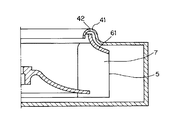
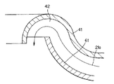
これに対し、特開平5‐296194号公報には、図14に示すようにベルマウス41とシュラウド61との隙間を少なくかつ長くし、さらに風の折り返し部42を設けることにより、流線21aに沿う風の流れを低減させるようにした遠心送風機が開示されている。この遠心送風機では、図15に示すように、ベルマウス41とシュラウド61とで形成される隙間を流線21aに沿って流れる風はスムーズな流れとなっているため、この流線21aに沿う風の流れを抑制するためには、隙間を極力詰めるか、あるいはベルマウス41とシュラウド61とで形成される隙間部をできるだけ長くする必要がある。
【0009】
ところが、ベルマウス41とシュラウド61との隙間を詰めようとした場合には、遠心多翼ファンロータ5の回転時にこれらベルマウス41とシュラウド61とが当たることのないように部品の加工精度を上げ、かつ組立精度も良くする必要があり、部品の製造や遠心送風ファンの組立に要するコストの上昇を招く。
【0010】
また、上記のコスト上昇を避けるため、ベルマウス41とシュラウド61との隙間を広げる代わりにこの隙間部を伸ばそうとした場合、ハウジング1を大きくしなくてはならず、限られた設置スペースに送風ファンを収める際に問題を生じることがあった。
【0011】
本発明の目的は、コスト上昇やハウジングの大型化を招くことなく、ハウジング内部に発生する不必要な空気の流れを軽減して騒音や効率の面で性能を向上させた遠心送風機を提供することにある。
【0012】
【課題を解決するための手段】
(1) 1実施の形態を示す図9〜図11を参照して説明をすると、請求項1の発明は、ハウジング1内に遠心多翼ファン5を設け、ハウジング1上面の空気取り入れ口2から遠心多翼ファン5内部に吸い込んだ空気を遠心多翼ファン5の外周面側へ送出し、さらにハウジング1内に設けた送風通路10を経てハウジング1の側面に開設した送風口13へ送出するようにした遠心送風機に適用される。そして遠心多翼ファン5の空気取り入れ側の全周に所定の長さにわたって設けられた円筒状の遮蔽板12と;ハウジング1の上面において遠心多翼ファン5の外周側に立設され、遮蔽板12の上端との間でラビリンスシールを構成する円筒状のリブ11と;円筒状のリブ11とハウジング1の内周面との間において、遠心多翼ファン5の回転方向に沿ってハウジング1内を略一周する間にその円弧半径を漸増せしめ、終端がハウジングの送風口13に至るように、ハウジングの1上面に立設された渦巻形状のリブ11hとを備えることにより上記問題点を解決する。
【0013】
【発明の効果】
以上説明したように本発明によれば、遠心多翼ファンロータに遮蔽板を設けるとともに、遠心多翼ファンの外周側において遮蔽板との間でラビリンスシールを構成する円筒状のリブと、このリブとの間に螺旋状の通風通路を形成する螺旋状のリブとをハウジング上面に立設させることにより、遠心送風機の送風通路内で発生する、遠心送風機の作動に好ましくない方向に流れる風による遠心多翼ファンロータの篭内への吹き込み、送風口隅部に発生する定在渦流、および送風通路内でファンブレードに吹き返す風により引き起こされる送風効率の低下及び騒音の発生を防止した。したがって、特別な装置を使うことなしに送風効率が高く、発生騒音の少ない高性能の遠心送風機を安価に提供することができる。
【0014】
【発明の実施の形態】
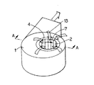
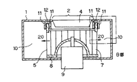
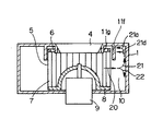
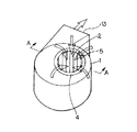
本発明による遠心送風機の第1の実施の形態を図1、図2、図3により説明する。なお、図12および図13に示した送風機と同様の箇所には同一の符号を付して相違点を主に説明する。図2は本発明による遠心送風機の具体的構造を示すもので、図1におけるA−A線断面を表している。ここで説明する遠心送風機は図12および図13に示した遠心送風機と同様に、ハウジング1で囲まれた送風通路内にモータ9で回転駆動される遠心多翼ファンロータ5を配設し、遠心多翼ファンロータ5の回転により、図12に示すとおり空気取り入れ口2から空気を吸い込み送風口13よりその空気を送出するものである。
【0015】
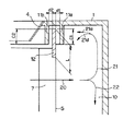
図3は図2のB部を拡大して示した簡略図である。
図3において、ハウジング1の上部には、遠心多翼ファンの軸心を中心とする同心円筒状にリブ11a、11bが2列に設けられている。
遮蔽板12は遠心多翼ロータファン5の吸入側端に高さLの円筒形状をなして設けられていて、ファンブレード7の空気吸い込み側端のそれぞれを連結して固定する。この遮蔽板12の端部はファンブレード7の上端面から上方に突出して2列のリブ11a、11bの間に挿入され、遮蔽板12の内周面とリブ11bの外周面との間、遮蔽板12の外周面とリブ11aの内周面との間にはそれぞれ間隔d2、d1だけ隙間が設けられている。この隙間d2、d1は、遠心多翼ファンロータ5の回転時に遮蔽板12がリブ11a、11bと接触しない範囲で小さな値に設定される。
【0016】
以上に述べた第1の実施の形態において、モータ9によって遠心多翼ファン5が回転して送風するときの風の流れについて、図3、図4を用いて説明する。
複数のファンブレード7の間から流線20に沿って送出された風はハウジング1の側壁に衝突した後、流線21、流線22に沿う方向に分流する。送風通路10の上側に分流して流線21に沿う風はハウジング1の内壁に衝突してその風向を変え、流線21aに沿う流れとなり、また、一部は流線21dに沿う流れとなる。
【0017】
流線21aに沿う風の流れはリブ11a、11bおよび遮蔽板12によって阻止される。これにより、流線21aに沿う風が再び遠心多翼ファン5の空気吸い込み側とベルマウス4との間を通って再び遠心多翼ファンロータ5の籠内に戻るのが防止されるとともに、流線21dに沿う風がファンブレード7に当たるのも防止される。この結果、従来例で問題となっていた送風効率の低下や騒音の増大といった不具合が抑制される。
【0018】
さらに、第1の実施の形態の遠心送風機は、遮蔽板12をリブ11a、11b間に挿入してラビリンス構造を採用しており、これにより、流線21aに沿う風が送風通路10から遮蔽板12の上端部を通ってベルマウス4側へ流れる空気の流量を効果的に抑制する。以下、この点を詳細に説明する。
【0019】
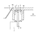
図4は、図3に示した第1の実施の形態の要部を流れる気流を説明した図である。送風通路10からベルマウス4側に流れ込む逆流aはハウジング1の上面に設けられた円筒状のリブ11a、11bの隅部に渦流b、dを形成するとともに遮蔽板12の上端付近に渦流cを形成する。これらの渦流b、c、dにより逆流aの実際の送風通路面積は減少する。また、これらの渦流b、c、dを形成するためのエネルギは、逆流aから供給される。これらの理由により、逆流aの流通抵抗が増大する。
【0020】
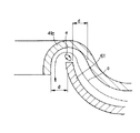
一方、図16は例えば特開平5−296194号公報に開示されているように断面形状が半円状の突環部41aをベルマウス41の周囲に設け、この半円状突環部41aの間にシュラウド61が位置するようにした場合の空気流を説明する図である。このような構造の場合、逆流aは渦流eを形成するが、図4に示すような渦流b、dは形成しない。従って図16に示す例は、図4に示す第1の実施の形態に比べて、逆流aの実際の送風通路面積は大きく、かつ、逆流aが渦流形成に分配するエネルギーも少ない。これらの理由により、寸法dが同じ場合、図4に示す第1の実施の形態は、図16に示す例に比べて逆流aを減少させることができる。
【0021】
なお、図3において、リブ11a、11bと遮蔽板12とのオーバーラップ量を示すc1、c2は等しくした例が示されているが、必ずしも等しくする必要はない。同様に、遮蔽板12とリブ11a、11bとの隙間d1、d2も必ずしも等しくする必要はない。
【0022】
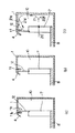
図5(a)〜(c)は本発明による第2〜第4の実施の形態の要部を説明する簡略図である。第1の実施の形態を示す図3では、送風通路10の上下方向のほぼ全域にわたって延在するファンブレード7の上端側を遮蔽板12により覆うようにしたが、第2〜第4の実施の形態を示す図5(a)〜(c)では、遮蔽板12を遠心多翼ファンロータ5の吸入側端面から上方に突設している。
【0023】
図5(a)、(b)、(c)のそれぞれは遮蔽板12がブレード7の送風通路側、中間、吸い込みロ側にぞれぞれ位置している場合を示しており、さらに図5(b)、(c)では、ハウジング1に設けた2列のリブ11a、11bのうち、中心側のリブ11bを省略し、ベルマウス4によつてリブ11bの機能を置き換えた例を示している。このようにしても第1の実施の形態と同様の作用効果を期することができる。
【0024】
図6は本発明による第5の実施の形態の要部を説明する簡略図である。この図6に示す第5の実施の形態においては、遠心多翼ファンロータ5の軸心近傍を中心とした同心円筒状に3つのリブ11c〜eをハウジング1上部に設け、2つの遮蔽板12a、12bを遠心多翼ファンロー夕5の空気吸い込み側端面に設けている。第1の発明の実施の形態のラビリンス構造を2段設けることで、流線21aに沿う風が再び遠心多翼ファンロータ5の空気吸い込み側とベルマウス4との間を通って再び遠心多翼ファンロータ5の籠内に戻るのを、図2、図3、図4に示した第1の発明の実施の形態に比べてさらに効果的に防止することができ、よりいっそうの送風効率の向上および発生騒音の低下が可能となる。
【0025】
図7は本発明による第6の実施の形態を説明する簡略図である。この例では、遠心多翼ファンロータ5に遮薮板12を設ける代わりに、ロータインレツトリング6によりファンブレード7の吸入側端を保持する一般的なファン構造を用いている。そして、ハウジング1上部に、遠心多翼ファンロータ5の軸心近傍を中心とする同心円状に2つの円弧状リブ11f及び11gを設け、このリブ11f、11gの間にロータインレットリング6およびファンブレード7が入り込むように構成されている。リブ11fは図2〜図5で説明してきた流線21dに沿う風の流れを防ぐのに十分な長さを有し、これにより、第1から第5の実施の形態で得られるものと同様の作用効果を得ることができる。さらにリブ11fの長さを延長することにより図7中に示す、流線21dに沿う風の遠心多翼ファンロータ5への吹き戻しを防ぐことができ、さらに騒音の低減および効率の改善を期することができる。
【0026】
図8は本発明による第7の実施の形態を説明する簡略図である。この例では第6の実施の形態におけるリブ11gを省略し、その機能をベルマウス4で代替している。これによっても、第6の実施の形態と同様の作用効果を得ることができる。
【0027】
以上では、流線21a、21dに沿う風の吹き返しによる効率低下、および騒音の発生を抑制する場合について説明してきたが、次に図13の流線21cで示す渦流について説明する。流線21cに沿って流れる渦流は送風通路10のコーナー近くを通過する流線21bに沿う風によって発生し、この渦流がハウジング1と衝突するときに騒音を発生するとともに送風通路10を流れる風との間に衝突が起こって送風効率が低下することは先に述べたとおりである。以下この渦流を解消するための実施の形態について説明する。
【0028】
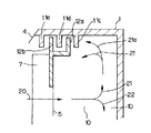
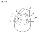
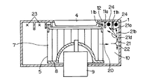
図9および図10は本発明による第8の実施の形態を説明する簡略図である。この実施の形態は、図2に示す第1の実施の形態で説明した構造に、さらに第3のリブ11hをハウジング1の上面に設置した例である。第3のリブは、図9の破線で示すように、遠心多翼ファンロータ5回転に伴う風の主流方向を示す流線23、流線24に沿う形で、ファン12の回転軸を中心として、送風通路10内を螺旋状にその曲率半径を漸増させ、最後は送風口13に沿うように設けられている。
【0029】
図9および図10において、流線21bに従う風の流れは、第3のリブ11hによりその方向を変え、流線23、流線24に沿う風の流れとなる。図の×印は紙面垂直で紙面表から裏方向に、また●印はその逆方向に流線が向いていることを示す。
【0030】
第3のリブ11hで阻止されずに流れる流線21a、流線21dに沿う風は遮蔽板12、および、リブ11aにより流れを阻止され、流線23、流線24に沿う風によって送風口13に向かう風に転換される。ハウジング1内の上方向へ向かった流線21に沿う流れはこのようにリブ11hや遮蔽板12、およびリブ11aによって流線23、流線24に沿う方向へ逐次変換され、送風口13へ導かれる。
【0031】
このようにして第8の実施の形態による遠心送風機では、流線21aに沿う風が再び遠心多翼ファンロータ5の空気吸い込み側とベルマウス4との間を通って再び遠心多翼ファンロータ5の籠内に戻るのを防止するとともに、流線21dに沿う風がファンブレード7に当たるのを防止し、さらには送風口の上隅部に発生する定在渦流を防止して、送風効率の低下や騒音増大などの不具合が発生することを防止し、遠心送風機の送風効率の向上及び低騒音化が達成できる。
【0032】
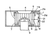
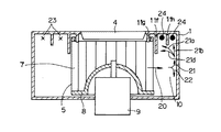
図11は本発明による第9の実施の形態を説明する簡略図である。この実施の形態は図7に示す第6の実施の形態で説明した構造に、さらに第8の実施の形態と同様のリブ11hをハウジング1に設置したものである。これによっても第8の実施の形態で得られるものと同一の作用効果を得ることを期することができる。
【図面の簡単な説明】
【図1】本発明の第1の実施の形態による遠心送風機の外観斜視図
【図2】図1の遠心送風機のA−A線断面図
【図3】図2におけるB部の詳細図
【図4】図2におけるB部の詳細図
【図5】(a)、(b)、(c)はそれぞれ本発明の第2〜第4の実施の形態による遠心送風機の要部断面図
【図6】本発明の第5の実施の形態による遠心送風機の要部断面図
【図7】本発明の第6の実施の形態による遠心送風機の要部断面図
【図8】本発明の第7の実施の形態による遠心送風機の要部断面図
【図9】本発明の第8の実施の形態による遠心送風機の外観斜視図
【図10】図9の遠心送風機のA−A線断面図
【図11】本発明の第9の実施の形態による遠心送風機の要部断面図
【図12】従来の遠心多翼送風機の外観斜視図
【図13】従来の遠心送風機の中を流れる空気の流線を示す図12のA−A線断面図
【図14】従来の遠心多翼送風機の要部を示す断面図
【図15】従来の遠心多翼送風機の要部を示す断面図
【図16】従来の遠心多翼送風機のベルマウス付近の断面図
【符号の説明】
1 ハウジング
2 空気取り入れ口
4、41 ベルマウス
5 遠心多翼ファンロータ
6 ロータインレットリング
7 ファンブレード
8 ロータ底部
9 モータ
10 送風通路
11 リブ
12 遮蔽板
13 送風口
20、21、22、23、24 流線
61 シュラウド[0001]
BACKGROUND OF THE INVENTION
The present invention relates to a centrifugal blower that improves air blowing performance and reduces noise.
[0002]
[Prior art]
As this type of centrifugal fan, the structure of the most common centrifugal multiblade fan is shown in FIGS. FIG. 12 is an external perspective view of a conventional example, and FIG. 13 is a cross-sectional view taken along line AA shown in FIG.
In this centrifugal blower, an
[0003]
The centrifugal
[0004]
The wind sent to the
[0005]
[Problems to be solved by the invention]
However, in the above prior art, the
[0006]
The wind along the
[0007]
When the airflow along the
[0008]
On the other hand, in Japanese Patent Application Laid-Open No. 5-296194, as shown in FIG. 14, the gap between the
[0009]
However, when trying to close the gap between the
[0010]
In addition, in order to avoid the above cost increase, when trying to extend the gap portion instead of widening the gap between the
[0011]
SUMMARY OF THE INVENTION An object of the present invention is to provide a centrifugal fan that improves the performance in terms of noise and efficiency by reducing unnecessary air flow generated inside the housing without increasing the cost or enlarging the housing. It is in.
[0012]
[Means for Solving the Problems]
(1) Referring to FIG. 9 to FIG. 11 showing one embodiment, the invention of
[0013]
【The invention's effect】
As described above, according to the present invention, the centrifugal multiblade fan rotor is provided with the shielding plate, and the cylindrical rib constituting the labyrinth seal with the shielding plate on the outer peripheral side of the centrifugal multiblade fan, and the rib The spiral ribs that form a spiral ventilation passage between the centrifugal blower and the centrifugal fan are erected on the upper surface of the housing, so that the centrifugal force generated by the wind flowing in a direction unfavorable for the operation of the centrifugal blower is generated. Blowing into the cage of the multiblade fan rotor, standing vortex generated at the corner of the air outlet, and reduction in air blowing efficiency and noise caused by the wind blowing back to the fan blade in the air passage were prevented. Therefore, it is possible to provide a high-performance centrifugal blower with high blowing efficiency and low noise generation without using a special device at low cost.
[0014]
DETAILED DESCRIPTION OF THE INVENTION
A first embodiment of a centrifugal blower according to the present invention will be described with reference to FIGS. In addition, the same code | symbol is attached | subjected to the location similar to the air blower shown to FIG. 12 and FIG. 13, and a difference is mainly demonstrated. FIG. 2 shows a specific structure of the centrifugal blower according to the present invention, and shows a cross section taken along line AA in FIG. In the centrifugal blower described here, similarly to the centrifugal blower shown in FIGS. 12 and 13, a centrifugal
[0015]
FIG. 3 is a simplified view showing the portion B of FIG. 2 in an enlarged manner.
In FIG. 3,
The
[0016]
In the first embodiment described above, the flow of wind when the centrifugal
The wind sent along the
[0017]
The flow of wind along the
[0018]
Furthermore, the centrifugal blower of the first embodiment employs a labyrinth structure by inserting the shielding
[0019]
FIG. 4 is a diagram illustrating the airflow flowing through the main part of the first embodiment shown in FIG. The reverse flow a flowing into the
[0020]
On the other hand, FIG. 16 shows, for example, a semicircular projecting ring portion 41a having a semicircular cross section provided around the
[0021]
In FIG. 3, an example is shown in which c1 and c2 indicating the overlap amount between the
[0022]
5 (a) to 5 (c) are simplified diagrams for explaining a main part of the second to fourth embodiments according to the present invention. In FIG. 3 which shows 1st Embodiment, although the upper end side of the
[0023]
5A, 5B, and 5C show cases where the shielding
[0024]
FIG. 6 is a simplified diagram for explaining a main part of the fifth embodiment according to the present invention. In the fifth embodiment shown in FIG. 6, three
[0025]
FIG. 7 is a simplified diagram for explaining a sixth embodiment according to the present invention. In this example, instead of providing the shielding
[0026]
FIG. 8 is a simplified diagram for explaining a seventh embodiment according to the present invention. In this example, the
[0027]
In the above, the case where the efficiency reduction due to the blowing of the wind along the
[0028]
9 and 10 are simplified views for explaining an eighth embodiment according to the present invention. This embodiment is an example in which a
[0029]
9 and 10, the flow of the wind according to the
[0030]
The wind along the
[0031]
In this way, in the centrifugal blower according to the eighth embodiment, the wind along the
[0032]
FIG. 11 is a simplified diagram for explaining a ninth embodiment according to the present invention. In this embodiment, a
[Brief description of the drawings]
1 is an external perspective view of a centrifugal blower according to a first embodiment of the present invention. FIG. 2 is a cross-sectional view taken along line AA of the centrifugal blower of FIG. 4 is a detailed view of part B in FIG. 2. FIGS. 5A, 5B, and 5C are cross-sectional views of the essential parts of centrifugal blowers according to second to fourth embodiments of the present invention, respectively. FIG. 7 is a cross-sectional view of an essential part of a centrifugal blower according to a fifth embodiment of the present invention. FIG. 7 is a cross-sectional view of an essential part of a centrifugal blower according to a sixth embodiment of the present invention. FIG. 9 is a perspective view of an external appearance of a centrifugal blower according to an eighth embodiment of the present invention. FIG. 10 is a cross-sectional view taken along line AA of the centrifugal blower of FIG. FIG. 12 is a cross-sectional view of the main part of a centrifugal fan according to a ninth embodiment of the present invention. FIG. 12 is an external perspective view of a conventional centrifugal multiblade fan. 12 is a cross-sectional view taken along the line AA of FIG. 12 showing the flow lines of air flowing through the blower. FIG. 14 is a cross-sectional view showing the main parts of a conventional centrifugal multiblade fan. FIG. 16 is a cross-sectional view of a conventional centrifugal multiblade blower near the bell mouth.
DESCRIPTION OF
Claims (1)
前記遠心多翼ファンの空気取り入れ側の全周に所定の長さにわたって設けられた円筒状の遮蔽板と、
前記ハウジング上面において、前記遠心多翼ファンの外周側に立設され、前記遮蔽板の上端との間でラビリンスシールを構成する円筒状のリブと、
前記円筒状のリブと前記ハウジングの内周面との間において、前記遠心多翼ファンの回転方向に沿って前記ハウジング内を略一周する間にその円弧半径を漸増し、終端が前記ハウジングの送風口に至るように、前記ハウジング上面に立設された渦巻形状のリブとを備えることを特徴とする遠心送風機。 A centrifugal multiblade fan is provided in the housing, and the air sucked into the centrifugal multiblade fan from the air intake port on the upper surface of the housing is sent to the outer peripheral surface side of the centrifugal multiblade fan, and further the air blow provided in the housing In a centrifugal blower that sends out to a blower opening established on the side of the housing through a passage,
A cylindrical shielding plate provided over a predetermined length all around the air intake side of the centrifugal multiblade fan;
Cylindrical ribs standing on the outer peripheral side of the centrifugal multiblade fan on the upper surface of the housing and constituting a labyrinth seal with the upper end of the shielding plate ;
Between the cylindrical rib and the inner peripheral surface of the housing, the arc radius is gradually increased while making one round of the inside of the housing along the rotational direction of the centrifugal multiblade fan. A centrifugal blower comprising a spiral rib erected on the upper surface of the housing so as to reach the mouth.
Priority Applications (1)
| Application Number | Priority Date | Filing Date | Title |
|---|---|---|---|
| JP21466496A JP3649815B2 (en) | 1996-08-14 | 1996-08-14 | Centrifugal blower |
Applications Claiming Priority (1)
| Application Number | Priority Date | Filing Date | Title |
|---|---|---|---|
| JP21466496A JP3649815B2 (en) | 1996-08-14 | 1996-08-14 | Centrifugal blower |
Publications (2)
| Publication Number | Publication Date |
|---|---|
| JPH1054388A JPH1054388A (en) | 1998-02-24 |
| JP3649815B2 true JP3649815B2 (en) | 2005-05-18 |
Family
ID=16659528
Family Applications (1)
| Application Number | Title | Priority Date | Filing Date |
|---|---|---|---|
| JP21466496A Expired - Fee Related JP3649815B2 (en) | 1996-08-14 | 1996-08-14 | Centrifugal blower |
Country Status (1)
| Country | Link |
|---|---|
| JP (1) | JP3649815B2 (en) |
Cited By (1)
| Publication number | Priority date | Publication date | Assignee | Title |
|---|---|---|---|---|
| EP2896838A4 (en) * | 2012-09-12 | 2016-06-29 | Soler & Palau Res Sl | Coupling between a centrifugal fan and the suction inlet thereof |
Families Citing this family (22)
| Publication number | Priority date | Publication date | Assignee | Title |
|---|---|---|---|---|
| KR100481797B1 (en) * | 1997-12-30 | 2005-06-27 | 한라공조주식회사 | Noise damping structure of a blower case |
| KR100550597B1 (en) * | 1998-11-14 | 2006-05-11 | 한라공조주식회사 | Multi fan blower |
| KR20010105614A (en) * | 2000-05-16 | 2001-11-29 | 구자홍 | Centrifugal fan |
| KR100748142B1 (en) * | 2001-08-27 | 2007-08-09 | 한라공조주식회사 | Assembly of fan and shroud |
| KR100748141B1 (en) * | 2001-08-27 | 2007-08-09 | 한라공조주식회사 | Assembly of fan and shroud |
| KR100748143B1 (en) * | 2001-09-05 | 2007-08-09 | 한라공조주식회사 | Assembly of axial fan and shroud |
| JP2004316448A (en) * | 2003-04-11 | 2004-11-11 | Daikin Ind Ltd | Centrifugal blower |
| JP3794423B2 (en) * | 2004-09-06 | 2006-07-05 | ダイキン工業株式会社 | Impeller of multi-blade fan and multi-blade fan equipped with the impeller |
| US7883312B2 (en) | 2005-03-31 | 2011-02-08 | Mitsubishi Heavy Industries, Ltd. | Centrifugal blower |
| JP4831811B2 (en) * | 2005-03-31 | 2011-12-07 | 三菱重工業株式会社 | Centrifugal blower |
| JP5005181B2 (en) | 2005-04-01 | 2012-08-22 | 日本電産サーボ株式会社 | Centrifugal fan |
| US7363762B2 (en) * | 2005-11-16 | 2008-04-29 | General Electric Company | Gas turbine engines seal assembly and methods of assembling the same |
| JP4882664B2 (en) * | 2006-10-23 | 2012-02-22 | パナソニック株式会社 | Washing and drying machine |
| JP4940084B2 (en) * | 2007-10-02 | 2012-05-30 | 日立アプライアンス株式会社 | Dryer and washing dryer |
| KR101703662B1 (en) * | 2010-08-27 | 2017-02-07 | 한온시스템 주식회사 | Blowing structure of air conditioner for vehicles |
| KR101692221B1 (en) * | 2010-08-31 | 2017-01-17 | 한온시스템 주식회사 | Blowing structure of air conditioner for vehicles |
| TWI464322B (en) | 2010-12-14 | 2014-12-11 | Delta Electronics Inc | Centrifugal fan |
| JP5769978B2 (en) * | 2011-01-27 | 2015-08-26 | ミネベア株式会社 | Centrifugal fan |
| JP6084632B2 (en) * | 2011-12-07 | 2017-02-22 | インテル・コーポレーション | Volume resistance blower device and system |
| JP5888494B2 (en) | 2011-12-15 | 2016-03-22 | 日本電産株式会社 | Centrifugal fan device |
| US10545546B2 (en) | 2018-02-23 | 2020-01-28 | Intel Corporation | Reversible direction thermal cooling system |
| EP3628872B1 (en) | 2018-09-27 | 2023-01-25 | INTEL Corporation | Volumetric resistance blowers |
-
1996
- 1996-08-14 JP JP21466496A patent/JP3649815B2/en not_active Expired - Fee Related
Cited By (1)
| Publication number | Priority date | Publication date | Assignee | Title |
|---|---|---|---|---|
| EP2896838A4 (en) * | 2012-09-12 | 2016-06-29 | Soler & Palau Res Sl | Coupling between a centrifugal fan and the suction inlet thereof |
Also Published As
| Publication number | Publication date |
|---|---|
| JPH1054388A (en) | 1998-02-24 |
Similar Documents
| Publication | Publication Date | Title |
|---|---|---|
| JP3649815B2 (en) | Centrifugal blower | |
| US7244099B2 (en) | Multi-vane centrifugal fan | |
| JP3491342B2 (en) | Axial fan | |
| KR20000047329A (en) | Stator for axial flow fan and shroud assembly with the same | |
| JP4831811B2 (en) | Centrifugal blower | |
| US20080253897A1 (en) | Axial Flow Fan | |
| CN209743192U (en) | Diagonal flow fan | |
| CN101270761A (en) | Centrifugal blower and air conditioner having same | |
| JP2010124534A (en) | Mixed flow fan for electric motors and motor equipped with this mixed flow fan | |
| AU2007234497B2 (en) | Multiblade centrifugal blower | |
| JP2007146709A (en) | Multi-blade centrifugal blower | |
| JPH102299A (en) | Centrifugal blower | |
| US7080970B2 (en) | Housing for axial flow heat-dissipating fan | |
| JPH06213198A (en) | Outdoor unit for air conditioner | |
| WO1998053211A1 (en) | Multi-blade centrifugal fan | |
| JP2006125229A (en) | Sirocco fan | |
| JPH07243397A (en) | Air blower | |
| JP2004316448A (en) | Centrifugal blower | |
| JP2010077851A (en) | Centrifugal blower | |
| KR100532052B1 (en) | Air Inhalation Structure of Blower | |
| KR20110026064A (en) | Blower for vehicle air conditioner | |
| JPH11289716A (en) | Cooling fan for electric motor | |
| JP2005201095A (en) | Centrifugal blower | |
| JP7213415B2 (en) | blower | |
| JP7655094B2 (en) | Centrifugal Blower |
Legal Events
| Date | Code | Title | Description |
|---|---|---|---|
| A977 | Report on retrieval |
Free format text: JAPANESE INTERMEDIATE CODE: A971007 Effective date: 20041004 |
|
| A131 | Notification of reasons for refusal |
Free format text: JAPANESE INTERMEDIATE CODE: A131 Effective date: 20041019 |
|
| A521 | Written amendment |
Free format text: JAPANESE INTERMEDIATE CODE: A523 Effective date: 20041215 |
|
| TRDD | Decision of grant or rejection written | ||
| A01 | Written decision to grant a patent or to grant a registration (utility model) |
Free format text: JAPANESE INTERMEDIATE CODE: A01 Effective date: 20050201 |
|
| A61 | First payment of annual fees (during grant procedure) |
Free format text: JAPANESE INTERMEDIATE CODE: A61 Effective date: 20050216 |
|
| R150 | Certificate of patent or registration of utility model |
Free format text: JAPANESE INTERMEDIATE CODE: R150 |
|
| LAPS | Cancellation because of no payment of annual fees |