JP3649814B2 - Electric car - Google Patents
Electric car Download PDFInfo
- Publication number
- JP3649814B2 JP3649814B2 JP20737396A JP20737396A JP3649814B2 JP 3649814 B2 JP3649814 B2 JP 3649814B2 JP 20737396 A JP20737396 A JP 20737396A JP 20737396 A JP20737396 A JP 20737396A JP 3649814 B2 JP3649814 B2 JP 3649814B2
- Authority
- JP
- Japan
- Prior art keywords
- battery
- motor
- battery case
- main frame
- attached
- Prior art date
- Legal status (The legal status is an assumption and is not a legal conclusion. Google has not performed a legal analysis and makes no representation as to the accuracy of the status listed.)
- Expired - Fee Related
Links
- 230000001105 regulatory effect Effects 0.000 claims description 8
- 238000001514 detection method Methods 0.000 description 11
- 238000006243 chemical reaction Methods 0.000 description 8
- 239000000463 material Substances 0.000 description 6
- 230000008602 contraction Effects 0.000 description 5
- 238000010586 diagram Methods 0.000 description 5
- 230000000694 effects Effects 0.000 description 2
- 229910000859 α-Fe Inorganic materials 0.000 description 2
- 229910000831 Steel Inorganic materials 0.000 description 1
- XAGFODPZIPBFFR-UHFFFAOYSA-N aluminium Chemical compound [Al] XAGFODPZIPBFFR-UHFFFAOYSA-N 0.000 description 1
- 229910052782 aluminium Inorganic materials 0.000 description 1
- 230000004888 barrier function Effects 0.000 description 1
- 230000005540 biological transmission Effects 0.000 description 1
- 239000004020 conductor Substances 0.000 description 1
- 230000001276 controlling effect Effects 0.000 description 1
- 229910001234 light alloy Inorganic materials 0.000 description 1
- 238000004519 manufacturing process Methods 0.000 description 1
- 239000010959 steel Substances 0.000 description 1
Images
Landscapes
- Arrangement Or Mounting Of Propulsion Units For Vehicles (AREA)
- Electric Propulsion And Braking For Vehicles (AREA)
Description
【0001】
【発明の属する技術分野】
本発明は、バッテリを電源とし、モータを駆動して走行する電動車に関する。
【0002】
【従来の技術】
従来、この種の電動車は、バッテリを電源とし、バッテリ1個を電源としてモータを駆動して走行するものが一般的に知られている。このようなバッテリは、設定距離を走行するために、それに見合った容量のバッテリを備えており、通常一種類だけ用意されている。
【0003】
しかしながら、このような電動車であれば、比較的短い距離を重量の重いものを積載して走行するとき、バッテリの重さが負担になる場合があったり、急いでいるときなど、充電時間が足りず充電不足で使用することがあり、バッテリ寿命を短くする恐れがあった。
【0004】
【発明が解決しようとする課題】
本発明は、上記欠点に鑑みなされたもので、走行距離や充電時間、重量に合わせてバッテリの選択ができ、最適の条件で使用できる電動車を提供することを課題とする。
【0005】
【課題を解決するための手段】
本発明は、駆動源となるモータと、該モータの駆動力で回転する駆動輪とを設けたメインフレームと、前記モータの電源となるバッテリ及び該バッテリを内蔵しメインフレームに取り付けられるバッテリケースからなるバッテリユニットとを備え、前記バッテリユニットは、容量の異なるバッテリを内蔵する複数種形成されてメインフレームに選択的に取り付けられ、前記複数種のバッテリユニットのそれぞれのバッテリケースは、外観上同一形状に形成されると共に、前記バッテリは、バッテリケースがメインフレームに取り付けられたときにバッテリケース内の下方に位置するようにバッテリケースに内蔵されることを特徴とする。
【0006】
また、それぞれのバッテリケースは、それぞれのバッテリケース内に形成された規制部材の位置によって内蔵するバッテリ容量を決定することを特徴とする。
【0007】
更に、規制部材は、バッテリの左右に形成されたボスと、バッテリの前後に形成された規制壁と、左右のボス間をバッテリ上を通って連結される規制板とによって構成されていることを特徴とする。
【0008】
容量の異なる複数のバッテリは、全て外観上同一形状のバッテリケースに収納されており、充電時間、走行距離、重量などの条件によって使用するバッテリを選択する。
【0009】
また、バッテリをバッテリケースに内蔵するとき、規制部材の位置によってバッテリの種類を判別することができ、製造上間違えることがない。
【0010】
【発明の実施の形態】
本発明の実施の形態を、電動自転車を例に、図1乃至図8に基づいて以下に詳述する。
【0011】
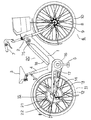
まず、電動自転車の全体構成について、図3に基づき説明をする。
【0012】
1は、前部に設けられたヘッドパイプ2、サドル3から下方に設けられたシートチューブ4と連結するメインフレームであり、該メインフレーム1は前記シートチューブ4とが連結する部分に人力によって回転することができるペダル5が取り付けられている。
【0013】
6は、ハンドル7の動きに連動し、ハンドル7操作によって走行方向を定める前輪で、該前輪6はスポーク8、リム9、タイヤ10から構成されている。
【0014】
11は、駆動輪となる後輪であり、該後輪11も、タイヤ12、リム13、スポーク14、それと後輪11を駆動するための駆動部15とから構成されている。
【0015】
16は、前記ペダル5の回転とともに回転する前スプロケットで、該前スプロケット16にはチェーン17がかかっており前スプロケット16の回転を前記駆動部15の車軸に設けた後スプロケット50に動力を伝達するようになっている。
【0016】
18は、モータ24の電源となるバッテリ19が収納されているバッテリケースで、該バッテリ19は1本1.2ボルトのセル電池19Aが20本直列接続されて、フィルム19Bによって固定されている。これらのバッテリーケース18、バッテリ19を合わせてバッテリユニット20という。また、バッテリ19は取り外し可能で充電の際は屋内で充電をすることができる。また、前記バッテリユニット20は、5Ahと2.5Ahの容量が異なる2種類あり、その2つのいづれかを選択して取り付けることができる。これらのバッテリケース18の形状は同じであり、容量が異なっても同じように取り付けることができる。
【0017】
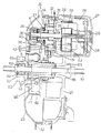
前述した駆動部15について、図6及び図7に具体的構成を示す。
【0018】
21は、メインフレーム1に固定して取り付けられた円盤状の固定側ケーシングで、22は、前記固定側ケーシング21と同軸で固定側ケーシング21外側を回転する回転側ケーシングである。これらの固定側ケーシング21と回転側ケーシング22とを合わせてハブを構成している。前記固定側ケーシング21は、2ミリの厚さを持った軽合金によって形成されている。
【0019】
23は、前記回転側ケーシング22の外周に設けられたU字状の環状リブで、該環状リブ23は前記回転側ケーシング22に複数個所で固定されており、環状リブ23からはタイヤ12が取り付けられているリム13に向かってスポーク14が張設されている。また、環状リブ23は、鋼板によって形成されており、2.3ミリの厚さを持って構成されている。該環状リブ23は、前記回転側ケーシング22と別の構成部品にし、スポーク14からの力がかかり強度が必要な環状リブ23には強い材料で厚くしてあり、比較的力のかからない回転側ケーシング22には、環状リブ23よりも弱い材料で、薄く構成し、材質、材厚を互いに変えている。このように構成することで、駆動部15全体を軽量にすることができ、また、材料を変えることでコストダウンすることができる。
【0020】
24は、駆動源となるモータで、25がロータ、26がステータである。該モータ24は、前記固定側ケーシング21に装着してあり、該モータ24の回転側ケーシング22から突出した部分にはモータカバー27によって施蓋し、モータ24の出力軸28をベアリング29によって支持している。
【0021】
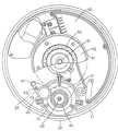
30は、前記固定側ケーシング21にネジ止めされ、保持部31に嵌合された遊星ローラ減速機構で、該遊星ローラ減速機構30は出力軸28と同一軸を中心として配置されている。
【0022】
前記遊星ローラ減速機構30の構成について説明をする。
【0023】
32は、前記保持部31にネジ止め固定された固定輪で、該固定輪32の内円には遊星ローラ33が4個設けられてあり、該遊星ローラ33の外周が、外側では前記固定輪32の内周に接し、内側ではモータ24の出力軸28に接するように配置している。また、遊星ローラ33の中心には出力ピン34が設けてあり、出力ピン34と遊星ローラ33との間にはニードルベアリング35が設けてある。
【0024】
該遊星ローラ減速機構30は、モータ24の出力軸28が回転すると、接している遊星ローラ33は出力ピン34を中心に自転を始めると共に固定輪32に接しているため、出力軸28を中心に公転を始める。この出力ピン34からの回転する出力を取り出すことでモータ24の出力を減速して取り出すことができる。
【0025】
36は、底面を前記出力ピン34に軸支し、出力軸28を貫通する円筒状の支持具で、該支持具36は出力軸28との間に軸受37を介して設けられ、更に先端側にはベアリング38を介して設けられている。
【0026】
39は、前記支持具36外周に装着された一方向クラッチで、該一方向クラッチ39は前記ペダル5からの力をモータ24に伝わらないようにし、モータ24の駆動力を回転側ケーシング22に伝える働きをする。
【0027】
40は、前記出力軸28に2つのベアリングを介し、更に前記一方向クラッチ39を介して出力軸28と同軸に装着された第1プーリーで、該第1プーリー40にはゴム製のベルト41が掛けられている。
【0028】
42は、前記ベルト41の他端が掛けられている第2プーリーで、該第2プーリー42は回転側ケーシング22にボルト43によって固定されている。また、第2プーリー42は中が空洞になっており、この中に後述するトルク検出部56が設けられている。
【0029】
44は、前記ベルト41の張りを調節するためのテンションプーリーで、該テンションプーリー44は支持体45の一端にローラ46が取り付けてあり、他端には固定側ケーシング21に取り付けるためのネジ47が設けてあり、ネジ47を取りつけてある部分を中心に支持体45が揺動可能であり、もう一方のネジ48を締め付けることでテンションプーリー44を固定し、前記ベルト41を押さえ、ベルト41の張りを調整することができる。
【0030】
49は、固定側ケーシング22に内蔵された制御基板であリ、該制御基板49は、プーリーのない部分に内蔵される。そして、制御基板49は後述するトルク検出部56からの出力結果に応じたモータ24の回転を制御するマイコン以外に、モータ24をPWM制御する駆動回路やマイコンに起動電圧を入力するための定電圧回路、トルク検出回路などが装備されている。
【0031】
50は、前記チェーン17が掛けられている後スプロケットであり、該後スプロケット50は車軸51に対してベアリング52を介して設けられ、一方向クラッチ53を介して後述する回動板57に取り付けられている。
【0032】
54は、車軸52にベアリング55を介して設けられている回動筒で、該回動筒54は回転側ケーシング22の回転とともに回転する。
【0033】
56は、第2プーリー42と車軸51近傍に取り付けられたトルク検出部であり、該トルク検出部56はチェーン17を介して動力伝達される人力駆動力、即ち人力トルクを検出するために設けられている。
【0034】
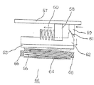
まず、前記トルク検出部56について、図8に基づき略図を用いて説明をする。
【0035】
回動板57は、車軸51と同心円状で、相対する2ケ所には、軸方向に押圧棒58と、変換棒59とが一体成形されている。前記押圧棒58は、釣鐘型の面をもって柱状に形成されており、釣鐘型の曲面部分で弾性体、即ちバネ60を押さえるようになっている。そして、回動板57は、バネ60を伸縮させ、バネ60の他端が第2プーリー42の内壁を押さえながら第2プーリー42が回転する。また、前記変換棒59は、車軸28方向に伸びる長方体で、先端部分が回転方向に向かって短くなるように斜めに形成してある。
【0036】
前記押圧棒58によって押さえられるバネ60は、他端を回転側ケーシング22の一部に接触させており、人力駆動力の伝達の順序として回動板57から押圧棒58、バネ60を伸縮させて回転側ケーシング22を回転させる。この時、伸縮されたバネ60の伸縮大きさに応じて回転側ケーシング22と少しの歪みを生じながら回動板57は回転する。そしてこの回動板57は、人力による歪みに応じて回動することになる。この時、同時に回動板57の少しの回動によって変換棒59も回動し、変換棒59先端に形成した傾斜部分61によって傾斜部分61と接する山形部62が押されて車軸28方向に移動する。この山形部62には磁性部材、即ちフェライトのリング63が取り付けられており、山形部62の移動によってリング63も移動するようになっている。このリング63の先端にはリング63を回動板57側に付勢するためのCリング64とバネ65が設けられている。よって回転側ケーシング22と回動板57が歪んだ分だけリング63が車軸28方向に移動するようになっている。
【0037】
66は、前記固定側ケーシング21で前記リング63近傍に設けられた磁気検出部材、即ちコイルで、該コイル66は前記リング63の接近によるインダクタンスの変化を電気的な信号に変換することができ、この出力を利用して人力のトルクを検出することができる。
【0038】
以上、図8に示す部材をまとめてトルク検出部56という。また、ここで変換棒59、山形部62、リング63、コイル66を検出部といい、これらによって弾性体の伸縮度合いを検出することができる。また、変換棒59、山形部62とを合わせて変換部材67と言い、回転方向の弾性体60の伸縮を車軸28方向の移動に変換する。
【0039】
上記構成において、リング63にフェライトを用いたが、アルミなどの導電性材料でリングを構成してもよい。また、弾性体をバネ60としたが、ゴムなどを弾性体とし、検出部としてこのゴムの伸縮を検出できるようなスケールを用いて構成しても良い。更に、弾性体を感圧ゴムとして、伸縮する圧力を電気的信号として取り出しても構わない。
【0040】
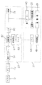
次に、以上の構成で、動力系統図について、図5に基づき説明をする。
【0041】
まず、人力駆動系について説明すると、ペダル5によって与えられた人力は、チェーン17によって後スプロケット50に伝達され、回動板57、バネ60を介して後輪11を回転させる。次に電動駆動系について説明すると、バネ60の伸縮の大きさ、即ち回動板57の回転移動距離を変換部材67によって車軸28方向の移動に変換し、その移動とともにリング63が移動するようにする。このリング63の移動をコイル66のインダクタンスの変化に変換し、電気信号として制御基板49に入力する。制御基板49は、固定側ケーシング21内に内蔵されている。そして、制御基板49にコイル66の信号を入力して、これに基づいたモータ24の回転となるように駆動信号を出力する。そして、モータ24の出力は遊星ローラ減速機構30によって減速され、第1プーリー40を介して後輪11が回転する。この制御における人力駆動力と電動駆動力の比率は1対1でモータ24による補助が行われる。
【0042】
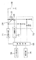
次に制御回路について、図4に基づき説明する。
【0043】
68は、前記モータ24を駆動用スイッチング素子69によってPWM制御する制御回路で、該制御回路68は前記トルク検出部56で検出したトルクに応じた出力でモータ24を駆動する。例えば、人力駆動力に対してモータ駆動力が1対1になるようにしてある。
【0044】
70は、前記制御回路68からの出力信号に基づき、前記スイッチング素子69をON−OFFするためのモータ駆動回路である。
【0045】
71は、24ボルトの電圧を5ボルトに降圧して制御回路68の電源となる定電圧回路である。
【0046】
72は、モータ24に並列に接続してあるフライホイールダイオードである。
【0047】
73は、バッテリ19の電流値と電圧値を制御回路68に入力する電流電圧検出回路で、該電流電圧検出回路73は、電流値を検出するためにスイッチング素子69に接続したシャント抵抗からの信号入力で行い、また、電圧値を検出するために電源供給ラインからの分圧値を制御回路68に入力することで行っている。この制御回路68は、入力した電流値を増幅したり、電流、電圧の所定値と比較したりする機能を有している。
【0048】
74は、前記電流電圧検出回路73の信号によってバッテリ容量が少なくなったことを知らせる報知回路で、例えばLEDやブザーなどから構成されている。
【0049】
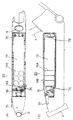
次に、バッテリユニット20の構造について図1及び図2に基づき説明する。
【0050】
まず、5Ahのバッテリユニット20について、図1に基づき説明する。5Ahの容量のバッテリユニット20は、バッテリケース18内に単1型電池の大きさを持つ1.2ボルトのセル電池19Aが20個直列に接続されており、10個ずつ2列に並べてフィルム19Bに収納されており、バッテリケース18に納められている。
【0051】
75は、バッテリケース18先端に形成された取っ手であり、該取っ手75はバッテリケース18に対して回動自在になってりる。
【0052】
また、バッテリケース18内の取っ手75近傍には、ヒューズ、出力用コネクタなどが収納されている。
【0053】
76は、バッテリの前後方向の動きを規制する規制壁であり、バッテリケース18前後に一体成形している。
【0054】
左右、上下はバッテリケース18の内側壁とバッテリ19外側壁とが略同一形状なので、バッテリケース内側壁によって動きが規制されている。
【0055】
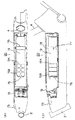
次に、2.5Ahのバッテリユニット20について、図2に基づき説明する。このバッテリユニット20は、バッテリケース18内に単2型電池の大きさを持つ1.2ボルトのセル電池19Aが20個直列に接続されており、10個ずつ2列に並べてフィルム19Bに収納されており、バッテリケース18に納められている。この場合、バッテリ19の大きさは、5Ahの場合より小さくなるので、バッテリケース18内部に2.5Ah用の長手方向の動きを抑えるための規制壁76と長手方向の横側の動きを規制するボス77を形成している。そして、バッテリ19の上下方向の動きを抑えるために、規制板78をネジによって止めてバッテリ19の上から押さえて固定してある。また、バッテリケース18内の取っ手75近傍には、5Ahのバッテリユニット20同様、ヒューズ、出力用コネクタなどが収納されている。上記の規制壁76、ボス77、規制板78を合わせて規制部材という。そして、バッテリケース18内に5Ahよりも容量の小さいバッテリ19が収納されるときは、メインフレーム1に取り付けられたときにバッテリ19が下方に位置するように規制部材の位置を決めて形成されている。
【0056】
これらのバッテリユニット20は、容量が異なるため、即ち充電時間、重量が異なってくる。そのため、充電時間、重量、満充電時の走行可能距離を使用者がいづれかを選択して取り付けることができる。本実施例では、2種類の容量の異なるバッテリユニット20を選択可能にしたが、2種類以上の容量のバッテリユニット20を用意し、それらから選択可能にしても構わない。そして、その時は規制部材の位置も変えて形成される。
【0057】
本実施例では、人力駆動力に対して同じ力の電動駆動力を出力する電動駆動力によって補助するタイプのアシスト式の自転車について示したが、人力駆動力と電動駆動力とが独立している電気自転車や、また、電気自動車などに使用できることはいうまでもない。
【0058】
【発明の効果】
本発明は、異なる容量のバッテリを内蔵したバッテリユニットを選択してメインフレームに取り付け可能であり、充電時間、重量、走行距離に合わせてバッテリを選択できるので、最適の条件でバッテリを選択することができ、使用勝手がよくなる。またバッテリは、バッテリユニットがメインフレームに取り付けられたときにバッテリケース内の下方に位置するように内蔵されるので、安定性がよくなる。さらに、容量の異なるバッテリを内蔵したバッテリユニットのバッテリケースは、外観上同一形状に形成されているので、バッテリの種類に係わらず、同様に取り付けられ、簡単に取り替えることができる等の効果を奏する。
【0059】
また、バッテリユニットは、それぞれのバッテリケース内に形成された規制部材の位置によって内蔵するバッテリ容量を決定するので、付け間違いがなく、組立て性が向上する等の効果を奏する。
【0060】
更に、規制部材は、バッテリの左右に形成されたボスと、バッテリの前後に形成された規制壁と、左右のボス間をバッテリ上を通って連結される規制板とによって構成されるので、簡単な構成で形成することができる等の効果を奏する。
【図面の簡単な説明】
【図1】本発明の実施例を示す1つのバッテリユニットの全体構成である。
【図2】同他のバッテリユニットの全体構成である。
【図3】同全体構成図である。
【図4】同制御回路である。
【図5】同動力系統図である。
【図6】同駆動部の側面断面図である。
【図7】同駆動部の平面構成図である。
【図8】同トルク検出部の動作の略図である。
【符号の説明】
24 モータ
11 駆動輪
1 メインフレーム
19 バッテリ
18 バッテリケース
77 ボス
76 規制壁
78 規制板[0001]
BACKGROUND OF THE INVENTION
The present invention relates to an electric vehicle that travels by driving a motor using a battery as a power source.
[0002]
[Prior art]
Conventionally, this type of electric vehicle is generally known to run by driving a motor using a battery as a power source and one battery as a power source. In order to travel a set distance, such a battery is provided with a battery having a capacity corresponding to the set distance, and usually only one type is prepared.
[0003]
However, with such an electric vehicle, the charging time may be short when traveling with a heavy load over a relatively short distance, such as when the weight of the battery may be a burden or when you are in a hurry. Insufficient charge may cause the battery life to be shortened.
[0004]
[Problems to be solved by the invention]
The present invention has been made in view of the above drawbacks, and an object of the present invention is to provide an electric vehicle that can select a battery according to the travel distance, charging time, and weight and can be used under optimum conditions.
[0005]
[Means for Solving the Problems]
The present invention includes a main frame provided with a motor serving as a drive source and drive wheels that rotate by the driving force of the motor, a battery serving as a power source for the motor, and a battery case containing the battery and attached to the main frame. A plurality of types of battery units having different capacities built therein and selectively attached to the main frame, and the battery cases of the plurality of types of battery units have the same shape in appearance. The battery is built in the battery case so as to be positioned below the battery case when the battery case is attached to the main frame .
[0006]
In addition, each battery case is characterized in that a built-in battery capacity is determined by a position of a regulating member formed in each battery case.
[0007]
Further, the restriction member is constituted by bosses formed on the left and right sides of the battery, restriction walls formed on the front and rear sides of the battery, and a restriction plate connected between the left and right bosses through the battery. Features.
[0008]
A plurality of batteries having different capacities are all housed in a battery case having the same shape in appearance, and a battery to be used is selected according to conditions such as charging time, travel distance, and weight.
[0009]
Further, when the battery is built in the battery case, the type of the battery can be determined based on the position of the regulating member, and there is no mistake in manufacturing.
[0010]
DETAILED DESCRIPTION OF THE INVENTION
An embodiment of the present invention will be described in detail below with reference to FIGS. 1 to 8, taking an electric bicycle as an example.
[0011]
First, the overall configuration of the electric bicycle will be described with reference to FIG.
[0012]
Reference numeral 1 denotes a main frame that is connected to a
[0013]
Reference numeral 6 denotes a front wheel that interlocks with the movement of the handle 7 and determines the traveling direction by operating the handle 7, and the front wheel 6 includes a spoke 8, a rim 9, and a tire 10.
[0014]
[0015]
Reference numeral 16 denotes a front sprocket that rotates with the rotation of the pedal 5, and a
[0016]
[0017]
A specific configuration of the
[0018]
[0019]
23 is a U-shaped annular rib provided on the outer periphery of the rotating
[0020]
[0021]
[0022]
The configuration of the planetary roller
[0023]
32 is a fixed ring fixed to the holding
[0024]
When the
[0025]
36 is a cylindrical support that pivotally supports the
[0026]
[0027]
[0028]
[0029]
44 is a tension pulley for adjusting the tension of the
[0030]
[0031]
[0032]
Reference numeral 54 denotes a rotating cylinder provided on the
[0033]
[0034]
First, the
[0035]
The rotating
[0036]
The other end of the
[0037]
66 is a magnetic detection member provided in the vicinity of the
[0038]
The members shown in FIG. 8 are collectively referred to as the
[0039]
In the above configuration, ferrite is used for the
[0040]
Next, a power system diagram with the above configuration will be described with reference to FIG.
[0041]
First, the human power drive system will be described. The human power given by the pedal 5 is transmitted to the
[0042]
Next, the control circuit will be described with reference to FIG.
[0043]
[0044]
[0045]
[0046]
[0047]
73 is a current-voltage detection circuit that inputs the current value and voltage value of the
[0048]
74 is a notification circuit for notifying that the battery capacity has been reduced by a signal from the current /
[0049]
Next, the structure of the
[0050]
First, the 5
[0051]
[0052]
A fuse, an output connector, and the like are housed near the
[0053]
[0054]
Since the inner wall of the
[0055]
Next, the 2.5
[0056]
These
[0057]
In the present embodiment, the assist type bicycle that is assisted by the electric driving force that outputs the same electric driving force as the human driving force is shown, but the human driving force and the electric driving force are independent. Needless to say, it can be used for electric bicycles and electric vehicles.
[0058]
【The invention's effect】
In the present invention, it is possible to select a battery unit including batteries with different capacities and attach them to the main frame. Since the battery can be selected according to the charging time, weight, and travel distance, the battery can be selected under optimum conditions Can be used, and it is easy to use. Further, since the battery is incorporated so as to be positioned below the battery case when the battery unit is attached to the main frame, the stability is improved. Furthermore, since the battery case of the battery unit including the batteries having different capacities is formed in the same shape in appearance, the battery case can be similarly installed and easily replaced regardless of the type of the battery. .
[0059]
In addition, since the battery unit determines the battery capacity to be built in depending on the position of the regulating member formed in each battery case, there is no mistake in attaching the battery unit, and the assemblability is improved.
[0060]
Furthermore, since the restriction member is configured by bosses formed on the left and right sides of the battery, restriction walls formed on the front and rear sides of the battery, and a restriction plate connected between the left and right bosses through the battery, it is simple. There are effects such as being able to be formed with various configurations.
[Brief description of the drawings]
FIG. 1 is an overall configuration of one battery unit showing an embodiment of the present invention.
FIG. 2 shows the overall configuration of another battery unit.
FIG. 3 is an overall configuration diagram of the same.
FIG. 4 is the same control circuit.
FIG. 5 is a diagram of the same power system.
FIG. 6 is a side sectional view of the drive unit.
FIG. 7 is a plan configuration diagram of the drive unit.
FIG. 8 is a schematic diagram of the operation of the torque detector.
[Explanation of symbols]
24 motor
11 Drive wheel 1 Main frame
19 Battery
18 Battery case
77 Boss
76 Regulatory barrier
78 Regulatory plate
Claims (3)
Priority Applications (1)
| Application Number | Priority Date | Filing Date | Title |
|---|---|---|---|
| JP20737396A JP3649814B2 (en) | 1996-08-06 | 1996-08-06 | Electric car |
Applications Claiming Priority (1)
| Application Number | Priority Date | Filing Date | Title |
|---|---|---|---|
| JP20737396A JP3649814B2 (en) | 1996-08-06 | 1996-08-06 | Electric car |
Publications (2)
| Publication Number | Publication Date |
|---|---|
| JPH1045077A JPH1045077A (en) | 1998-02-17 |
| JP3649814B2 true JP3649814B2 (en) | 2005-05-18 |
Family
ID=16538655
Family Applications (1)
| Application Number | Title | Priority Date | Filing Date |
|---|---|---|---|
| JP20737396A Expired - Fee Related JP3649814B2 (en) | 1996-08-06 | 1996-08-06 | Electric car |
Country Status (1)
| Country | Link |
|---|---|
| JP (1) | JP3649814B2 (en) |
Families Citing this family (1)
| Publication number | Priority date | Publication date | Assignee | Title |
|---|---|---|---|---|
| CN103579682B (en) * | 2012-08-09 | 2015-09-30 | 华硕电脑股份有限公司 | Battery and method of making the same |
-
1996
- 1996-08-06 JP JP20737396A patent/JP3649814B2/en not_active Expired - Fee Related
Also Published As
| Publication number | Publication date |
|---|---|
| JPH1045077A (en) | 1998-02-17 |
Similar Documents
| Publication | Publication Date | Title |
|---|---|---|
| JP3306309B2 (en) | Assist electric vehicle | |
| EP0760335B1 (en) | motorvehicle | |
| EP1886913B1 (en) | Electrically assisted bicycle | |
| JP3691132B2 (en) | Assisted vehicle | |
| JP3480978B2 (en) | Bicycle wheel with solar cell drive | |
| JP2001199379A (en) | Motor-assisted bicycle | |
| JP3649814B2 (en) | Electric car | |
| JP3306299B2 (en) | Electric car | |
| JP2001097274A (en) | Vehicle with auxiliary power | |
| JP2011143752A (en) | Power assisted bicycle | |
| JP2011143751A (en) | Power assisted bicycle | |
| JP2001122184A (en) | Vehicle with auxiliary power | |
| JP2001080570A (en) | Vehicle with auxiliary motive power | |
| JP2001080569A (en) | Vehicle with auxiliary motive power | |
| JP3710906B2 (en) | Vehicle with auxiliary power | |
| JPH1016869A (en) | Electric vehicle | |
| JP3996255B2 (en) | Electric motorcycle | |
| JPH092369A (en) | Bicycle with auxiliary driving force | |
| JP7037994B2 (en) | Controls, human-powered vehicles, and control methods | |
| JPH09315376A (en) | Reduction gear for motor car | |
| JP3524639B2 (en) | wheelchair | |
| JPH05105146A (en) | Motorcycle with electric motor | |
| KR20220008163A (en) | Assist Wheel Generator For Electric Powered Vehicle | |
| JPH0858671A (en) | Power assist device for bicycle | |
| JP3922485B2 (en) | Coasting control device for electric auxiliary wheelchair |
Legal Events
| Date | Code | Title | Description |
|---|---|---|---|
| A977 | Report on retrieval |
Free format text: JAPANESE INTERMEDIATE CODE: A971007 Effective date: 20040929 |
|
| A131 | Notification of reasons for refusal |
Free format text: JAPANESE INTERMEDIATE CODE: A131 Effective date: 20041012 |
|
| A521 | Request for written amendment filed |
Free format text: JAPANESE INTERMEDIATE CODE: A523 Effective date: 20041203 |
|
| TRDD | Decision of grant or rejection written | ||
| A01 | Written decision to grant a patent or to grant a registration (utility model) |
Free format text: JAPANESE INTERMEDIATE CODE: A01 Effective date: 20050208 |
|
| A61 | First payment of annual fees (during grant procedure) |
Free format text: JAPANESE INTERMEDIATE CODE: A61 Effective date: 20050216 |
|
| LAPS | Cancellation because of no payment of annual fees |