JP3648317B2 - Power carrier - Google Patents
Power carrier Download PDFInfo
- Publication number
- JP3648317B2 JP3648317B2 JP01514096A JP1514096A JP3648317B2 JP 3648317 B2 JP3648317 B2 JP 3648317B2 JP 01514096 A JP01514096 A JP 01514096A JP 1514096 A JP1514096 A JP 1514096A JP 3648317 B2 JP3648317 B2 JP 3648317B2
- Authority
- JP
- Japan
- Prior art keywords
- body frame
- seat
- vehicle body
- vehicle
- power
- Prior art date
- Legal status (The legal status is an assumption and is not a legal conclusion. Google has not performed a legal analysis and makes no representation as to the accuracy of the status listed.)
- Expired - Fee Related
Links
Images


Landscapes
- Vehicle Step Arrangements And Article Storage (AREA)
- Body Structure For Vehicles (AREA)
- Arrangement Or Mounting Of Propulsion Units For Vehicles (AREA)
Description
【0001】
【発明の属する技術分野】
本発明は、動力運搬車に関するものである。
【0002】
【従来の技術】
従来、動力運搬車の一形態として、車体フレームの下方に走行部を設けると共に、車体フレーム上の前部に運転部と原動機部とを左右幅方向に隣接させて配置する一方、後部に荷台を配置したものがある。
【0003】
そして、オペレータが運転部の床部へ乗降する際には、同運転部側の車体外部より床部に足を掛けて乗降するようにしている。
【0004】
【発明が解決しようとする課題】
ところが、上記した動力運搬車では、オペレータは運転部の床部へ乗降する際に、同運転部側の車体外部より乗降するしかないために、同運転部側に障害物等がある場合には乗降できないという不具合がある。
【0005】
【課題を解決するための手段】
そこで、本発明では、車体フレームの下方に走行部を設けると共に、車体フレーム上の前後一側部に運転部と原動機部とを左右幅方向に隣接させて配置する一方、前後他側部に荷台を配置した動力運搬車において、運転部は、車体フレームの前端部に、操作レバーを取付けた操作コラムを立設し、同操作コラムと荷台との間に座席を配置して、同座席と操作コラムとの間に位置する車体フレーム上に床部を形成し、原動機部は、上記座席の側方でかつ荷台に近接させて配置し、上記操作コラムの側方に位置する車体フレーム上にはステップ部を上記床部と連続させて形成して、床部とステップ部とにより車体フレーム上を左右幅方向に横断して通り抜け可能な昇降通路を形成した動力運搬車であって、操作コラムの側方に位置する車体フレームの前端部に、角部切欠状の傾斜面を形成し、同傾斜面側よりステップ部への乗降を可能としたことを特徴とする動力運搬車を提供せんとするものである。
【0006】
また、本発明は、原動機部を被覆するボンネットに乗降用取手を設けたこと、及び座席を垂直方向の軸線廻りに前後方向転換自在とし、同座席の原動機部側の側方位置に前後進変速レバーを下端を枢支して配置すると共に、同前後進変速レバーの下端枢支位置を、車体の前後方向と略直交し、かつ、上記座席の垂直回転中心線を通って左右幅方向に伸延する仮想直線上に配置したことにも特徴を有する。
【0007】
【実施例】
以下に、本発明の実施例を図面を参照しながら説明する。
【0008】
図1〜図3に示すAは、本発明に係る動力運搬車であり、同動力運搬車Aは、左右一対のクローラ式の走行部1,1間に連結基枠2を横架し、同連結基枠2上に車体フレーム3を設け、同車体フレーム3の前部左右側にそれぞれ運転部4と原動機部5とを隣接させて配置すると共に、車体フレーム3の後部に荷台6を配置している。
【0009】
運転部4は、図1〜図3に示すように、車体フレーム3の前部左側に床部7を形成し、同床部7上において、前部と後部にそれぞれ前後側操作コラム8,9を前後に対向させて立設し、各操作コラム8,9にそれぞれ操作レバー10,10,11,11 を取付け、両操作コラム8,9の中間に座席支持台12を設け、同座席支持台12上に座席13を垂直回転中心線Cを中心に回転自在に取付けて、同座席13を前方又は後方へ選択的に向きを変更可能としている。
【0010】
そして、座席13の内側方位置には、図1〜図3に示すように、操作ボックス14を配置し、同操作ボックス14に前後進変速レバー15を取付けており、同前後進変速レバー15は、下端を枢支してレバーガイド溝16に沿わせて前後回動操作自在とすると共に、同前後進変速レバー15の下端枢支位置は、車体の前後方向と略直交し、かつ、前記座席13の垂直回転中心線Cを通る左右幅方向に伸延する仮想直線L上に配置して、前後進変速レバー15を垂直に起立させた中立操作位置にて、同前後進変速レバー15と座席13の垂直回転中心線Cとが左右に平行状態となるようにしている。17,18 はアクセルペダル、19,20 はブレーキペダル、21,22 はクラッチペダル、23は駐車ブレーキレバー、24はダンプレバー、25は前側門型ガードフレーム、26は後側門型ガードフレームである。
【0011】
このようにして、オペレータは前方へ向けた座席13に着座して前側操作コラム8に取付けた操作レバー10,10 や各種ペダル17,19,21を操作することも、また、180 度反転させて後方へ向けた座席13に着座して後側操作コラム9に取付けた操作ハンドル11,11 や各種ペダル18,20,22を操作することもでき、作業条件等に応じて荷台6を進行方向の前方に見ながら操向操作や荷台6のダンプ操作を行なうことも、また、荷台6を背にして操向操作することもできるようにしている。
【0012】
この際、前後進変速レバー15は、中立操作位置にて座席13の垂直回転中心線Cと左右に平行状態に配置して座席13の前後方向の向きにかかわりなく、常時内側方に位置するようにしているために、オペレータは迅速かつ確実に前後進変速レバー15を操作することができる。
【0013】
ここで、本実施例では、便宜上、車体フレーム3の運転部4側を前部とし、荷台6側を後部として説明しているが、上記したように、座席13の向きを荷台6側に向けるように前後方向転換した場合には、進行方向は前後反対となり、運転部4と荷台6との前後位置関係も反対となる。
【0014】
原動機部5は、図1〜図3に示すように、車体フレーム3上において、前記操作ボックス14の右側方にエンジン30等を搭載し、同エンジン30等をボンネット31により被覆し、同ボンネット31の天井壁の内側寄り前部位置に乗降用取手32を取付けている。
【0015】
そして、ボンネット31の前方に位置する車体フレーム3上にはステップ部33を運転部4の床部7と同一平面上にて連続させて形成し、同床部7とステップ部33とにより、車体フレーム3上を左右幅方向に横断して通り抜け可能な乗降通路34を形成している。
【0016】
しかも、車体フレーム3の原動機部5側の前端部には、角部切欠状の傾斜面35を形成し、同傾斜面35側よりステップ部33への乗降を可能としている。
【0017】
さらに、車体フレーム3には、図1〜図3に示すように、ガードフレーム35を取付けており、同ガードフレーム35は、上下一対のフレーム形成体35a,35b の左側端部を、車体フレーム3の左側前部に同フレーム形成体35a 、35b の中途部を固定し、同車体フレーム3の前端面及び前記傾斜面35に沿わせて左右幅方向へ伸延させ、同フレーム形成体35a,35b の右側端部を車体フレーム3の右側端部に固定し、傾斜面35に対向する各フレーム形成体35a,35b の右側部分には、すべり止め体36,36 を取付けている。37は固定ブラケット、38は前照灯である。
【0018】
このようにして、運転部4の床部7への乗降を行なう際には、車体の左側前部より床部7へ乗降する通常の乗降形態と、車体の右側前部よりガードフレーム35のすべり止め体36上に足を掛けると共に、ボンネット31に取付けた乗降用取手32を把持してステップ部33へ乗降し、乗降通路34を通って床部7へ行き来する乗降形態とが採れるようにしている。
【0019】
そして、単に、車体フレーム3上を横断する必要のある場合にも、乗降通路34を通って通り抜けができるという便利さがある。
【0020】
この際、乗降通路34を形成する床部7とステップ部33は、同一水平面状に形成しているために、オペレータはスムーズに乗降通路34を通行できる。
【0021】
【発明の効果】
本発明によれば、次のような効果が得られる。
【0022】
(1) 請求項1記載の本発明では、運転部は、車体フレームの前端部に、操作レバーを取付けた操作コラムを立設し、同操作コラムと荷台との間に座席を配置して、同座席と操作コラムとの間に位置する車体フレーム上に床部を形成し、原動機部は、上記座席の側方でかつ荷台に近接させて配置し、上記操作コラムの側方に位置する車体フレーム上にはステップ部を上記床部と連続させて形成して、床部とステップ部とにより車体フレーム上を左右幅方向に横断して通り抜け可能な昇降通路を形成した動力運搬車であって、操作コラムの側方に位置する車体フレームの前端部に、角部切欠状の傾斜面を形成し、同傾斜面側よりステップ部への乗降を可能としたために、オペレータは、乗降通路を利用して車体の左右側いずれかの方向からでも適宜乗降することができると共に、車体フレームの傾斜面に近接した位置より、ステップ部上に乗ることができ、同ステップ部より傾斜面側より降りることができるため、停車位置での障害物等により乗降できないという不具合の発生を防止することができる。
【0023】
(2) 請求項2記載の本発明では、原動機部を被覆するボンネットに乗降用取手を設けているために、オペレータは、車体フレームの傾斜面に近接した位置より乗降用取手を把持することにより、ステップ部上に楽に乗ることができると共に、同ステップ部より乗降用取手を把持して傾斜面側より楽に降りることができる。
【0024】
(3) 請求項3記載の本発明では、座席を垂直方向の軸線廻りに前後方向転換自在とし、同座席の原動機部側の側方位置に前後進変速レバーを下端を枢支して配置すると共に、同前後進変速レバーの下端枢支位置を、車体の前後方向と略直交し、かつ、上記座席の垂直回転中心線を通って左右幅方向に伸延する仮想直線上に配置しているために、オペレータは、座席を前後いずれの方向に向けて着座した場合にも、前後進変速レバーとの相対的前後位置関係を、左右の位置関係に違いはあるものの、一定に保つことができて、楽にレバー操作を行うことができる。
【図面の簡単な説明】
【図1】本発明に係る動力運搬車の側面図。
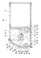
【図2】同動力運搬車の平面図。
【図3】同動力運搬車の正面図。
【符号の説明】
A 動力運搬車
1 走行部
2 連結基枠
3 車体フレーム
4 運転部
5 原動機部
6 荷台[0001]
BACKGROUND OF THE INVENTION
The present invention relates to a power vehicle.
[0002]
[Prior art]
Conventionally, as one form of a power vehicle, a traveling unit is provided below the body frame, and a driving unit and a motor unit are disposed adjacent to each other in the left-right width direction at the front part on the body frame, while a loading platform is provided at the rear part. There is something arranged.
[0003]
When the operator gets on and off the floor of the driving unit, he / she gets on and off the floor from outside the vehicle body on the driving unit side.
[0004]
[Problems to be solved by the invention]
However, in the power vehicle described above, when the operator gets on and off the floor of the driving unit, the operator has to get on and off from the outside of the vehicle body on the driving unit side. There is a problem that you cannot get on and off.
[0005]
[Means for Solving the Problems]
Therefore, in the present invention, a traveling unit is provided below the body frame, and the driving unit and the motor unit are disposed adjacent to each other in the left-right width direction on one side part on the front and back on the body frame, while the loading platform is disposed on the other side part on the front and rear sides. In the power truck with the position of the vehicle, the driving section stands on the front end of the body frame with an operation column attached with an operation lever, and a seat is placed between the operation column and the loading platform. A floor portion is formed on the vehicle body frame positioned between the column and the prime mover portion is disposed on the side of the seat and close to the loading platform, and on the vehicle body frame positioned on the side of the operation column. A power carrier vehicle in which a step portion is formed continuously with the floor portion, and a lift passage is formed by the floor portion and the step portion so as to pass through the body frame in the left-right width direction . Body frame located on the side To the front end portion to form a corner notch shape of the inclined surface, is to St. provide power transportation vehicle, characterized in that allowed the passenger to step portion than the inclined surface.
[0006]
The present invention also providing the ingress-egress handle the bonnet covering the prime mover part, and the freely back and forth turning the seat in the vertical direction of the axis around forward-reverse the lateral position of the prime mover side of the seat The shift lever is pivotally supported at the lower end, and the lower end pivot position of the forward / reverse shift lever is substantially perpendicular to the longitudinal direction of the vehicle body and extends in the lateral width direction through the vertical rotation center line of the seat. It is also characterized by being arranged on an extending virtual straight line.
[0007]
【Example】
Embodiments of the present invention will be described below with reference to the drawings.
[0008]
1 to 3 is a power vehicle according to the present invention, and the power vehicle A has a connecting base frame 2 horizontally mounted between a pair of left and right crawler
[0009]
As shown in FIGS. 1 to 3, the
[0010]
As shown in FIG. 1 to FIG. 3, an
[0011]
In this way, the operator can sit on the
[0012]
At this time, the forward / reverse
[0013]
In this embodiment, for the sake of convenience, the
[0014]
As shown in FIGS. 1 to 3, the
[0015]
A
[0016]
Moreover, a corner-notched
[0017]
Further, as shown in FIGS. 1 to 3, a
[0018]
In this way, when getting on and off the floor 7 of the
[0019]
In addition, even when it is necessary to cross over the
[0020]
At this time, since the floor portion 7 and the
[0021]
【The invention's effect】
According to the present invention, the following effects can be obtained.
[0022]
(1) In the present invention as set forth in
[0023]
(2) In the second aspect of the invention, because they provided a passenger handle for the bonnet covering the prime mover part, the operator is to grasp the ingress-egress handle from a position close to the inclined surface of the vehicle body frame Thus, it is possible to easily get on the step portion, and to easily get off from the inclined surface side by gripping the handle for getting on and off from the step portion.
[0024]
(3) In the present invention as set forth in
[Brief description of the drawings]
FIG. 1 is a side view of a power vehicle according to the present invention.
FIG. 2 is a plan view of the power vehicle.
FIG. 3 is a front view of the power vehicle.
[Explanation of symbols]
A
Claims (3)
運転部は、車体フレームの前端部に、操作レバーを取付けた操作コラムを立設し、同操作コラムと荷台との間に座席を配置して、同座席と操作コラムとの間に位置する車体フレーム上に床部を形成し、
原動機部は、上記座席の側方でかつ荷台に近接させて配置し、上記操作コラムの側方に位置する車体フレーム上にはステップ部を上記床部と連続させて形成して、
床部とステップ部とにより車体フレーム上を左右幅方向に横断して通り抜け可能な昇降通路を形成した動力運搬車であって、
操作コラムの側方に位置する車体フレームの前端部に、角部切欠状の傾斜面を形成し、同傾斜面側よりステップ部への乗降を可能としたことを特徴とする動力運搬車。 A power transport vehicle having a traveling part provided below the body frame and a driving part and a motor part adjacent to each other in the left-right width direction on one side part on the front and back sides of the body frame, and a loading platform on the other side part In
The driving unit stands on the front end of the body frame with an operation column attached with an operation lever. A seat is placed between the operation column and the loading platform, and the vehicle body is located between the seat and the operation column. Forming a floor on the frame,
The prime mover part is arranged on the side of the seat and close to the cargo bed, and on the vehicle body frame located on the side of the operation column, a step part is formed continuously with the floor part,
A power vehicle that forms an elevating passage that can be passed through a vehicle body frame in the left-right width direction by a floor portion and a step portion ,
A power transport vehicle characterized in that a corner notch-shaped inclined surface is formed at a front end portion of a vehicle body frame located on a side of an operation column, and the stepped portion can be boarded / exited from the inclined surface side.
Priority Applications (1)
| Application Number | Priority Date | Filing Date | Title |
|---|---|---|---|
| JP01514096A JP3648317B2 (en) | 1996-01-31 | 1996-01-31 | Power carrier |
Applications Claiming Priority (1)
| Application Number | Priority Date | Filing Date | Title |
|---|---|---|---|
| JP01514096A JP3648317B2 (en) | 1996-01-31 | 1996-01-31 | Power carrier |
Publications (2)
| Publication Number | Publication Date |
|---|---|
| JPH09207827A JPH09207827A (en) | 1997-08-12 |
| JP3648317B2 true JP3648317B2 (en) | 2005-05-18 |
Family
ID=11880518
Family Applications (1)
| Application Number | Title | Priority Date | Filing Date |
|---|---|---|---|
| JP01514096A Expired - Fee Related JP3648317B2 (en) | 1996-01-31 | 1996-01-31 | Power carrier |
Country Status (1)
| Country | Link |
|---|---|
| JP (1) | JP3648317B2 (en) |
-
1996
- 1996-01-31 JP JP01514096A patent/JP3648317B2/en not_active Expired - Fee Related
Also Published As
| Publication number | Publication date |
|---|---|
| JPH09207827A (en) | 1997-08-12 |
Similar Documents
| Publication | Publication Date | Title |
|---|---|---|
| EP2307262B1 (en) | Floorboard for a vehicle | |
| US7673920B2 (en) | Operator's station structure for work vehicle | |
| JP3648317B2 (en) | Power carrier | |
| JP7246193B2 (en) | Transport vehicle in railway tunnel | |
| US11400896B2 (en) | Vehicle | |
| JP2025141297A (en) | Work vehicle | |
| JP4808397B2 (en) | forklift | |
| JP7296058B2 (en) | Vehicle electric parking brake device | |
| JP4304289B2 (en) | Transporter | |
| JP7747677B2 (en) | Rolling device and rolling method | |
| JP4161032B2 (en) | Transporter | |
| JP2023007622A (en) | Service car | |
| US20250313282A1 (en) | Work Vehicle | |
| JP2022169334A (en) | multipurpose vehicle | |
| TWI640241B (en) | Towing vehicle | |
| JPH0235591Y2 (en) | ||
| JP6388247B2 (en) | Truck driver's seat | |
| JP4423873B2 (en) | Seedling planting machine | |
| JP3785421B2 (en) | Power carrier | |
| JP2025161232A (en) | Work vehicle | |
| JP6315405B2 (en) | Transporter operation device | |
| JP4214186B2 (en) | Transporter | |
| JPH0515207A (en) | Riding type work machine | |
| JP2005182215A (en) | Traveling operating device for work vehicle | |
| JPH09202220A (en) | Passenger working vehicle |
Legal Events
| Date | Code | Title | Description |
|---|---|---|---|
| A977 | Report on retrieval |
Free format text: JAPANESE INTERMEDIATE CODE: A971007 Effective date: 20040709 |
|
| A131 | Notification of reasons for refusal |
Free format text: JAPANESE INTERMEDIATE CODE: A131 Effective date: 20040727 |
|
| A521 | Written amendment |
Free format text: JAPANESE INTERMEDIATE CODE: A523 Effective date: 20040927 |
|
| TRDD | Decision of grant or rejection written | ||
| A01 | Written decision to grant a patent or to grant a registration (utility model) |
Free format text: JAPANESE INTERMEDIATE CODE: A01 Effective date: 20050201 |
|
| A61 | First payment of annual fees (during grant procedure) |
Free format text: JAPANESE INTERMEDIATE CODE: A61 Effective date: 20050214 |
|
| R150 | Certificate of patent or registration of utility model |
Free format text: JAPANESE INTERMEDIATE CODE: R150 |
|
| S111 | Request for change of ownership or part of ownership |
Free format text: JAPANESE INTERMEDIATE CODE: R313117 |
|
| R350 | Written notification of registration of transfer |
Free format text: JAPANESE INTERMEDIATE CODE: R350 |
|
| FPAY | Renewal fee payment (event date is renewal date of database) |
Free format text: PAYMENT UNTIL: 20080218 Year of fee payment: 3 |
|
| FPAY | Renewal fee payment (event date is renewal date of database) |
Free format text: PAYMENT UNTIL: 20100218 Year of fee payment: 5 |
|
| FPAY | Renewal fee payment (event date is renewal date of database) |
Free format text: PAYMENT UNTIL: 20100218 Year of fee payment: 5 |
|
| FPAY | Renewal fee payment (event date is renewal date of database) |
Free format text: PAYMENT UNTIL: 20110218 Year of fee payment: 6 |
|
| LAPS | Cancellation because of no payment of annual fees |