JP3641193B2 - Vertical heat treatment apparatus, heat treatment method, and heat insulation unit - Google Patents
Vertical heat treatment apparatus, heat treatment method, and heat insulation unit Download PDFInfo
- Publication number
- JP3641193B2 JP3641193B2 JP2000199992A JP2000199992A JP3641193B2 JP 3641193 B2 JP3641193 B2 JP 3641193B2 JP 2000199992 A JP2000199992 A JP 2000199992A JP 2000199992 A JP2000199992 A JP 2000199992A JP 3641193 B2 JP3641193 B2 JP 3641193B2
- Authority
- JP
- Japan
- Prior art keywords
- unit
- heating element
- heat
- temperature
- heat treatment
- Prior art date
- Legal status (The legal status is an assumption and is not a legal conclusion. Google has not performed a legal analysis and makes no representation as to the accuracy of the status listed.)
- Expired - Fee Related
Links
Images


Description
【0001】
【発明の属する技術分野】
本発明は縦型熱処理装置及び熱処理方法並びに保温ユニットに関する。
【0002】
【従来の技術】
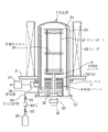
半導体デバイスの製造装置の一つとして縦型熱処理装置が知られている。この熱処理装置は多数枚のウエハを一括して熱処理するバッチ式のものであり、図14に減圧CVDを行う装置について概略図を示す。1はウエハボートであり、このウエハボート1は多数枚のウエハWを棚状に保持して図示しないエレベータにより、二重構造の反応管11及び筒状のマニホールド12よりなる反応容器内に搬入される。このとき反応容器は蓋体10により気密に塞がれる。反応容器内は、反応管11を囲むヒータ13により所定温度に加熱されると共に、排気管14により所定の圧力まで減圧される。そして成膜ガスがガス供給管15を通じて反応容器の下部側から供給され、薄膜の成分に分解されてウエハW上に堆積し、残りのガスは内管11aの天井部から内管11aと外管11bとの間の空間を下降していく。
【0003】
またウエハボート1の下には例えば石英よりなる筒状体の中に石英ウール等を収納してなる保温ユニット16を介在させてウエハWの置かれる雰囲気を蓋体10の外側から断熱して保温するようにし、更にウエハボート1の下端側には製品ウエハWを置かずにサイドウエハなどと呼ばれるダミーウエハWを数枚載置している。
【0004】
【発明が解決しようとする課題】
ところでウエハWの置かれる雰囲気の熱を外部にできるだけ逃がさないようにするために保温ユニット16の熱容量は大きく設定されている。このため処理雰囲気の温度を目標の処理温度まで昇温して温度を安定化させるときに、保温ユニット16の昇温が遅れ、処理雰囲気から保温ユニット16側に熱が流れてしまう。この結果温度が安定する時間(リカバリータイム)が長く、スループットの低下の要因になっており、更にまた十分に長いリカバリータイムをとらないとバッチ処理毎の再現性が悪い。
【0005】
また保温ユニット16により処理雰囲気と反応容器の外部との間の熱の流れを遮断するようにしてはいるが、ウエハボート1のウエハ載置領域の下部側は放熱量が多いのでウエハボート1の最下段から数段上まではサイドウエハ(ダミーウエハ)を置くようにしており、このため製品ウエハWの載置領域が狭くならざる得ない。従ってウエハボート1におけるウエハの収納可能枚数を多くしても、1バッチ処理当りの製品ウエハWの処理枚数が少なくなってしまい、結局スループットの向上の妨げとなっている。
【0006】
更にまたガス供給管15を通じて反応容器内に導入された成膜ガスは保温ユニット16の横を通って上昇していくが、保温ユニット16の温度が低いので特にガス流量が大きい場合には、ウエハWの置かれている処理雰囲気に達する未反応ガスの量が多くなる。このため処理雰囲気の中で分解するガスの量が多くなり、場所によって活性種の生成量が変わってくるので、このことがウエハWの膜厚に反映され、ウエハW間、及びウエハW面内における膜厚の均一性を悪くしている一因になっている。
【0007】
そこで本発明者は、このような課題を解決するために保温ユニットに発熱体ユニットを設けることを検討しているが、その実現にあたっては、発熱体ユニットの温度制御をどのようしして行うのか、発熱体ユニットからの蓋体側への放熱をいかにして抑えるか、更には保持具を回転させる場合どのような構造が適切か、などといった問題が積まれている。
【0008】
本発明はこのような事情の下になされたものであり、その目的は、縦型熱処理装置の処理雰囲気の温度を速やかに安定させかつ処理雰囲気からの外部への放熱を抑えることにあり、更にその実現手段として発熱体ユニットを用いる場合の適切な構成を提供することにある。
【0009】
【課題を解決するための手段】
本発明は、蓋体の上に支持された保持具に多数の被処理体を棚状に保持させ、前記保持具を反応容器内に下方側から搬入すると共に前記蓋体により反応容器の下端を気密に塞ぎ、前記反応容器内を加熱雰囲気にして被処理体に対して熱処理を行う縦型熱処理装置を対象としている。
【0010】
本発明は、前記蓋体と保持具との間にて、保持具の底部に対向するように設けられ、抵抗発熱体をセラミックスの中に封入してなる面状の発熱体ユニットと、
この発熱体ユニットの下方側に設けられ、石英板の一面に黒色膜層が形成された遮熱板と、を備えたことを特徴とする。遮熱板は石英板の一面に黒色膜層が形成される代わりに、石英板体の中に黒色膜層が封じ込められて構成されているものであってもよい。
【0011】
この発明によれば、保持具の下方側に発熱体ユニットを設けているので、反応容器内の処理雰囲気から下部側へ放熱される放熱量が少なくなるので、処理雰囲気を目標温度に速やかに安定させることができ、また温度が安定する処理領域を広く確保することができると共に、断熱効果及び熱応答性が向上する。
【0015】
更に他の発明は、保持具を回転させる構造とする場合、発熱体ユニットの中央部に貫通されると共に上部側と下部側とに分割可能に構成され、保持具を鉛直軸のまわりに回転させるための回転軸と、この回転軸の下端部に接続された回転駆動部と、を備えた構成とすることができる。
【0016】
更に他の発明は、蓋体の上に支持された保持具に多数の被処理体を棚状に保持させ、前記保持具を反応容器内に下方側から搬入すると共に前記蓋体により反応容器の下端を気密に塞ぎ、前記反応容器内を加熱雰囲気にして被処理体に対して熱処理を行う縦型熱処理装置に用いられる保温ユニットにおいて、
前記蓋体の上に載置されるリング状の底面部及びリング状の上面部を第1の保護管で連結して対向させると共に第1の保護管の上下を夫々上面部及び底面部に開口させてなる断熱ユニットと、
空洞のリング状体の下面を開口した形状であって、その下端部が前記断熱ユニットの上面部に接した状態で着脱自在に載置されることによりその内部空間がその外部空間から区画されるカバー体と、
前記カバー体内に配置され、リング状の石英プレート内に高純度の炭素素材よりなるヒータ線を封入してなる発熱体ユニットと、
前記石英プレートの下面側に接続され、前記ヒータ線に給電するための給電線が挿入された第3の保護管と、を備え、
前記第3の保護管は第1の保護管内に挿入され、当該第1の保護管の下方から伸び出し、
前記断熱ユニット、カバー体、発熱体ユニットの各々の中央部の開口は、保持具を回転させるための回転軸が貫通するためのものであることを特徴とする。
【0017】
【発明の実施の形態】
図1は本発明の縦型熱処理装置の実施の形態を示す全体構成図、図2は縦型熱処理装置の概観図である。先ずこれらの図を用いて装置の概要について簡単に説明する。図1中2は、例えば石英で作られた内管2a及び外管2bよりなる二重管構造の反応管であり、反応管2の下部側には金属製の筒状のマニホールド3が設けられている。
【0018】
前記内管2aは上端が開口されており、マニホールド3の内方側にて支持されている。外管2bは上端が塞がれており、下端がマニホールド3の上端に気密に接合されている。この例では、内管2a、外管2b及びマニホールド3により反応容器が構成されている。31はベースプレートである。
【0019】
前記反応管2内には、多数枚例えば126枚の被処理体をなすウエハWが各々水平な状態で上下に間隔をおいて保持具であるウエハボート21に棚状に載置されている。ウエハボート21は図2に示すように天板22及び底板23の間に複数本の支柱24を設け、この支柱24にウエハWの周縁部を保持する溝が形成されて構成されている。このウエハボート21は蓋体32の上に保温ユニット4の設置領域を介して保持されている。この保温ユニット4に関しては後で詳述する。前記蓋体32は、ウエハボート21を反応管2内に搬入、搬出するためのボートエレベータ33の上に搭載されており、上限位置にあるときにはマニホールド3の下端開口部、即ち反応管2とマニホールド3とで構成される反応容器の下端開口部を閉塞する役割を持つものである。
【0020】
また反応管2の周囲には、これを取り囲むように例えば抵抗加熱体よりなるヒータ25が設けられている。図1には示していないが、ヒータ25の周囲には断熱層が設けられ、更にその外側には外装体が設けられていてこれらにより加熱炉20(図2参照)が構成される。
【0021】
前記マニホールド3の周囲には複数のガス供給管が設けられ、複数の処理ガスを内管2aの中に供給できるようになっている。図1ではそのうち1本のガス供給管34を示してあり、このガス供給管34はバルブV1、流量計MFC及びバルブV2を介してガス供給源35に接続されている。またマニホールド3には、内管2aと外管2bとの間の空間から排気できるように排気管36が接続されており、真空ポンプ37により反応管内を所定の減圧雰囲気に維持できるようになっている。
【0022】
次に前記保温ユニット4及びこれに関連する部位について図3〜図5を参照しながら説明する。保温ユニット4は、セラミックス製例えば石英製の断熱ユニット40を備えており、この断熱ユニット40は各々円形の上面部41及び底板部42(図5では底板部42の外周部が省略してある)と、これら上面部41及び底板部42間を連結する、周方向に間隔をおいて設けられた3本の支柱部43 (図4参照)と、を備えている。これら3本の支柱部43の各々には上下に多数の溝44(図5参照)が形成されており、これら3本の支柱部43の溝44内に断熱部材である石英フィン45(図4では示していない)が挿入されて石英フィン45が多段に配列されている。石英フィン45はこれよりも上方側の熱が蓋体32側に放熱するのを抑えるためのものである。なお断熱部材としては石英フィン45に限らず発泡石英のブロック体などであってもよい。
【0023】
更に前記断熱ユニット40の上面部41と底面部42との間には、第1の保護管46及び第2の保護管47が周方向に間隔をおいて設けられ、両保護管46、47の両端は夫々上面部41及び底面部42に開口している。
【0024】
前記断熱ユニット40の上面部41の上には、蓋体32側への放熱を抑えるための遮熱板48(図4では示していない)が載置されている。この遮熱板48は例えば図6に示すように例えば透明な石英板48aの中に例えばカ−ボンからなる黒色膜層48bが封入されて構成されている。この黒色膜層48bはチタン膜や炭化ケイ素膜などであってもよく、また石英板48aの中に封じ込まれていなくとも、石英板48aの一面側に形成されていてもよい。
【0025】
前記遮熱板48の上側には隙間を介して例えば面状の発熱体ユニット5が設けられている。この発熱体ユニット5は、金属不純物の少ない抵抗発熱体をセラミックス例えば石英の中に封入されて構成されるものであり、この例では図7に示すように例えば厚さ8mm程度の石英製の円板状体(石英プレート)51中に高純度の炭素素材よりなるヒータ線52を渦巻状に配置して構成されている。また互に隣り合うヒータ線52、52の間に石英を介在させてもよく、この場合石英よりなる渦巻状の区画壁の間にヒータ線52が配線されることになる。発熱体ユニット5は、保温効果を大きくするためにウエハWと同じかそれよりも大きいサイズであることが好ましい。
【0026】
前記発熱体ユニット5の石英プレ−ト51の周縁部下面側には、第3の保護管53が接続されおり、前記ヒ−タ線52に給電するための給電線54は図7(b)に示すように第3の保護管53の接続部位にまとめられ、そこから当該保護管53内に挿入されている。なお図では詳しく表していないが、給電線54は各々細い石英管内に封入された状態で保護管53内を通っている。そしてこの第3の保護管53は前記断熱ユニット40の上面部41に開口している前記第1の保護管46内に挿入され、更に蓋体32を貫通して当該蓋体32の下面側にて固定されている。従って第3の保護管53は発熱体ユニット5の支持体の役割も持っている。
【0027】
また前記断熱ユニット40の上面部41及び底面部42、石英フィン45、遮熱板48並びに発熱体ユニット5の中央には、ウエハボ−ト21を回転させるための後述の回転軸が貫通する孔部41a,42a,45a,48a及び5aが夫々形成されている。前記上面部41の上には、発熱体ユニット5及び遮熱板48を覆う、中央部に孔部55aが形成された例えば円筒状(リング状)の石英製のカバ−体55が載置されている(着脱自在に設けられている)。従って発熱体ユニット5は、このカバ−体55及び前記上面部41により囲まれる空間内に置かれることになり、処理雰囲気から隔離されるので、反応生成物が付着しにくくなる。
【0028】
一方前記ウエハボ−ト21は、前記カバ−体55及び断熱ユニット4の中央の孔部55a,48a,41a,45a,42a内を通って蓋体32の下側まで貫通している回転軸26の上にテ−ブル27を介して搭載されている。この回転軸26は図3及び図8に示すように上下に分離できるように、下端に凹部SAが形成された上側回転軸26Aと、上端に凸部SBが形成された下側回転軸26Bとから構成されており、凹部SAと凸部SBとが嵌合している。上側回転軸26A及び下側回転軸26Bは例えば夫々石英及び金属で作られており、両者の材質の熱膨張係数を考慮して、プロセス温度において両者が密な嵌合状態となってガタツキがないように寸法を設定しておく。また図8に同時に示すように例えば下側回転軸26Bの中に温度調整手段例えばヒ−タ28を埋設し、ヒ−タ28の発熱量を調整して下側回転軸26Bの温度を制御し、これにより金属の熱膨張を調整するようにしてもよい。
【0029】
前記断熱ユニット4に設けられた第2の保護管47内には、熱電対及びその導線を石英管内に封入してなる第1の温度検出ユニット60が挿入されており、その先端部はL字型に屈曲されて発熱体ユニット5と遮熱板48との間に位置している。この第1の温度検出ユニット60内の先端部の熱電対のセンサ部は第1の温度検出部61をなすものである。第1の温度検出ユニット60の基端側は蓋体32を気密に貫通している。
【0030】
更に前記蓋体32には、熱電対及びその導線を石英管内に封入してなる第2の温度検出ユニット70が気密に挿入されて立ち上げられており、その先端部はL字型に屈曲されてウエハWの近傍例えばウエハボ−ト21の下方側近傍に位置している。この第2の温度検出ユニット70内の先端部の熱電対のセンサ部は第2の温度検出部71をなすものである。なお前記温度検出ユニット60(70)を蓋体32に固定するにあたっては、図9に示すように温度検出ユニット60(70)の石英管に例えば突起60aを形成する一方、蓋体32の貫通穴60bを前記突起60aを含む石英管の横断面形状に適合する形状とし、こうすることによって石英管の回転防止と位置決めを行うようにしている。
【0031】
図10は発熱体ユニット5の温度制御系を示す図であり、発熱体ユニット5の温度制御を行う制御部62は、第1の温度検出部61及び第2の温度検出部71の両方の温度検出信号に基づいて発熱体ユニット5の供給電力を制御するように構成されている。図では制御部62は略解的に記載してあるが、実際には発熱体ユニット5の電源部、及び供給電力を例えば位相制御する制御回路、並びに前記両方の温度検出信号に基づいて位相制御信号を作成する演算部などを含んでいる。即ちこの実施の形態では、発熱体ユニット5の温度制御は、発熱体ユニット5の近傍の温度とウエハWの近傍の温度とに基づいて行われる。
【0032】
次に上述実施の形態の作用について説明する。ここでは具体的な処理の一例としてHTO(High Temperature Oxide)と呼ばれる酸化膜をCVD処理で成膜する例を挙げる。先ず被処理体であるウエハWを所定枚数ウエハボート21に棚状に保持して、ボートエレベータ33を上昇させることにより反応容器内に搬入する。ウエハボート21の搬入時には反応容器の処理雰囲気は例えば600℃程度に維持されており、ウエハボート21が搬入されて反応容器の下端開口部(詳しくはマニホールド3の下端開口部)が蓋体32により塞がれた後、ヒータ25により処理雰囲気を例えば800℃前後まで昇温させると共に、排気管36を通じて真空ポンプ37により反応容器内を所定の真空度まで減圧する。
【0033】
一方ウエハボ−ト21が反応容器の下方側にて待機している間は、ロ−ディングエリア(搬入、搬出を行う部屋)にて発生しているファンフィルタからの風の影響を避けるために例えば第2の温度検出部71を使用せずに第1の温度検出部61だけを用いて発熱体ユニット5の温度制御が行われ、発熱体ユニット5は例えば100℃付近に維持される。そしてウエハボ−ト21の搬入が開始されると、発熱体ユニット5は昇温を開始し(温度設定値を高くし)、発熱体ユニット5の温度を例えば成膜時の処理雰囲気の温度よりも少し高い温度まで昇温する。発熱体ユニット5及び処理雰囲気が各々目標温度に到達する時点は例えばほぼ同じタイミングである。ウエハボ−ト21が反応容器内に搬入された後は、第1の温度検出部61及び第2の温度検出部71の両方の温度検出値に基づいて発熱体ユニット5の温度制御が行われる。具体的には、温度検出部61及び71の検出値を夫々T6、T7とすると、比率をAとし、T6・A+T7(1−A)を比制御温度とする。そして比率Aの値を調整したり、温度設定値を調整することによりウエハWについて適切な温度制御を行うようにする。
【0034】
その後温度安定化のための時間(リカバリータイム)だけ処理を行わずに待機し、しかる後、2本のガス供給管34(既述のように図1では1本しか示していない)からジクロロシラン(SiH2 Cl2 )ガスと一酸化二窒素(N2 O)ガスとを反応容器(反応管1とマニホールド3)内に供給しながら反応容器内の圧力を例えば所定の真空度に維持する。またこのとき回転軸26を回転させてウエハボート21を回転させる。
【0035】
ここで発熱体ユニット5の表面近傍の温度は例えばおよそ840℃に設定されるため、発熱体ユニット5の周囲及びそれよりも少し下方側は処理雰囲気の温度800℃付近よりも高くなっている。このため反応容器の下部側に供給されたジクロロシランガス及び一酸化窒素ガスは保温ユニット4の横を通るときに分解が進み、分解が進んだ状態で処理雰囲気内に拡散していき、ウエハW上に活性種が堆積されてシリコン酸化膜が成膜される。その後、ヒータ25の電力をコントロールして反応容器内を降温すると共に、発熱体ユニット5の供給電力をゼロにして発熱体ユニット5を降温させ、例えば処理雰囲気の温度が600℃になった時点にてウエハボート21を下降させる。
【0036】
上述実施の形態によれば次のような効果がある。
【0037】
(1)ウエハボ−ト21と蓋体32との間に発熱体ユニット5を設けているため、処理雰囲気から保温ユニット4を介して外部に放熱される熱量が少なくなる。そして保温ユニット4は発熱体ユニット5を備えていることから保温性がよく、このため熱容量は小さくてよいので保温ユニット4全体が温まる速度も早い。このようなことから処理雰囲気の温度を目標温度に到達した後、その温度に安定させるための時間(リカバリ−タイム)が短くて済み、スル−プットの向上が図れる。またバッチ処理毎のリカバリ−タイムのばらつきも小さくなるので処理の再現性がよくなる。
【0038】
(2)上述のように保温ユニット4の保温効果が大きいことから温度の均一性の高い領域が下方まで広がり、このためウエハボ−ト21の下部において今まで温度が低いためサイドウエハを載置せざるを得なかった領域にも製品ウエハを載置することができ、1バッチ当たりの処理枚数を多くできるので、この点からもスル−プットが向上する。
【0039】
(3)ガス供給管34を通じて反応容器内に供給された成膜ガスは発熱体ユニット5により加熱され、処理雰囲気に到達する前にある程度分解されるので、処理雰囲気における未反応ガスの量が少なくなる。この結果ウエハボ−ト21に配列された各ウエハWの間において、また各ウエハWの面内において活性種の濃度の均一性が高くなり、ウエハW間及びウエハW面内における膜厚の均一性が高くなる。
【0040】
(4)ウエハボ−ト21が反応容器内に搬入された後は、発熱体ユニット5の近傍の温度検出値とウエハWの近傍の温度検出値とに基づいて発熱体ユニット5の温度を制御しているため、ウエハWを速やかに昇温させながら発熱体ユニット5に無理な負荷がかかるおそれもない。例えば発熱体ユニット5の近傍の温度のみを検出する場合には、ウエハWの温度が低いにもかかわらず発熱体ユニット5による昇温制御が不十分であったり、逆にウエハWの近傍の温度のみを検出する場合には、発熱体ユニット5の負荷は限界近くまできているのにもかかわらずウエハWの温度を上げるために更に昇温しようとして使用寿命を短くするといったおそれがあるので、片方の温度検出値を用いる場合に比べてこの実施の形態の温度制御の方が優れている。
【0041】
(5)更にまたウエハボ−ト21が反応容器の下方側のロ−ディングエリアで待機しているときには、カバ−体55で覆われて風の影響のない第1の温度検出部61の温度検出値に基づいて発熱体ユニット5が制御されるので、安定した温度制御ができる。この温度制御が不安定だと発熱体ユニット5が反応容器内に入ったときに反応容器内の温度安定領域の昇温のスタ−ト温度が変わり、このためカ−ブも変わってくるので処理の再現性が悪くなる。またロ−ディングエリアにおいて発熱体ユニット5の温度が一時的に高くなって搬送機構などのメカ系に熱による悪影響を及ぼす場合もある。
【0042】
(6)発熱体ユニット5の下方側に遮熱板48を設けているので、発熱体ユニット5からの熱が下方側に逃げていくのを抑えることができ、高い保温性が得られ、断熱ユニット40を小さくすることができ、あるいはなくすことができる。従って断熱ユニット40の熱容量が小さくなるので下段側のウエハWの昇温が早くなり、スル−プットを向上することができる。また発熱体ユニット5の投入パワ−を小さくできるので、効率よく加熱できる。
【0043】
(7)ウエハボ−ト21の回転軸26を上下に分離できるように構成することにより、例えば石英製の上側回転軸26Aを洗浄したり交換したりするときに上方へ抜き出すことができ、分解作業が容易である。
【0044】
以上において、ウエハボ−ト21がロ−ディングエリアにあるときには第1の温度検出部61のみで発熱体ユニット5の温度制御を行うことが好ましいが、第2の温度検出部71を併用してもよい。また第1の温度検出部61は発熱体ユニット5と一体に設けるようにしてもよく、この場合発熱体ユニット5の中に設けるようにしてもよいし、発熱体ユニット5の石英プレ−ト51の外面に第1の温度検出ユニット60の石英管を溶接するなどしてもよい。第1の温度検出ユニットは第1の温度検出部61に加えて、過昇温防止用の温度検出部を内蔵するようにしてもよい。なお温度検出部61、71及び過昇温防止用の温度検出部としては放射温度計などを用いてもよい。
【0045】
更に発熱体ユニット5の温度制御を行うにあたって、プロセス時には上述のように第1の温度検出部61及び第2の温度検出部71の両方を用いることが好ましいが、本発明は、第1の温度検出部61のみを用いる場合も含むものとする。
更にまた発熱体ユニット5は抵抗発熱体52(発熱領域)を複数の領域に分割し、分割領域毎に温度制御(いわゆるゾ−ン制御)を行うようにしてもよい。図11は抵抗発熱体52の分割のパタ−ンの例を示すものであり、図11(a)は発熱体ユニット5を周方向に4分割したもの、図11(b)は発熱体ユニット5を同心円状に分割したもの、図11(c)は発熱体ユニット5を同心円状にかつ周方向に4分割したものを表している。同心円状に分割する例として、図示の便宜上抵抗発熱体52をリング状に記載しているが、実際には例えば同心円状に4分割し、各分割領域ごとに抵抗発熱体5を所定の配置パタ−ンで配置すればよい。
【0046】
図12は、発熱体ユニット5は発熱領域をP1〜P4の4個に分割した場合の制御系の一例を示すものであり、52−1〜52−4は各分割領域P1〜P4に割り当てられた抵抗発熱体、Q1〜Q4は各分割領域P1〜P4に割り当てられた第1の温度検出部、81〜84は各分割領域P1〜P4に割り当てられた制御部である。この例では各制御部81〜84が温度設定値と第1の温度検出部Q1〜Q4の温度検出値と第2の温度検出部の温度検出値とに基づいて抵抗発熱体P1〜P4の発熱量を制御している。このような例によれば、周方向の保温性を均一化でき、あるいは外側の発熱量を大きくして面内の保温性の均一化を図れるなど、きめ細かな温度制御ができる。
【0047】
本発明では、発熱体ユニット5が過昇温した場合に火災を防止し、人的、物的な事故を防ぐための安全対策として図13に示すように例えば発熱体ユニット5の下面側や蓋体32の下面側やロ−ディングエリア内に過昇温防止用の温度検出部91、92、93を設け、その温度検出信号に基づいて発熱体ユニット5の給電を止めるようにすることが好ましい。なお94、95は加熱炉20のヒ−タの過昇温防止用の温度検出部である。
【0048】
以上において本発明は、減圧CVD装置に適用することに限らず、いわゆる酸化、拡散炉にも適用することができる。
【0049】
【発明の効果】
本発明によれば、反応容器の蓋体と被処理体の保持具との間に発熱体ユニットを設けているので、温度安定化に要する時間を短くできる。そして発熱体ユニットの近傍の温度と被処理体の近傍の温度とを検出し、それらの温度検出値に基づいて発熱体ユニットを制御することにより、被処理体を速やかに昇温させることができ、また発熱体ユニットに無理な負荷がかかるおそれもない。
【図面の簡単な説明】
【図1】本発明の縦型熱処理装置の実施の形態の全体構成を示す縦断側面図である。
【図2】上記の装置の概観を示す斜視図である。
【図3】この実施の形態に用いられる発熱体ユニット及び断熱ユニットを含む保温ユニットを示す断面図である。
【図4】保温ユニット及び回転軸を示す分解斜視図である。
【図5】断熱ユニットを示す横断平面図である。
【図6】遮熱板を示す断面図である。
【図7】 発熱体ユニットの断面及び平面を示す説明図である。
【図8】回転軸が分解された様子を示す概略説明図である。
【図9】温度検出ユニットの石英管を蓋体に装着する構造を示す斜視図である。
【図10】発熱体ユニットの温度制御系を示す説明図である。
【図11】発熱体ユニットの抵抗発熱体を分割した例を示す平面図である。
【図12】発熱体ユニットにおける分割された抵抗発熱体を制御するための制御回路を示す説明図である。
【図13】処理雰囲気を加熱するためのヒ−タ及び発熱体ユニットの過昇温を防止するためのセンサ−の配置の一例を示す説明図である。
【図14】従来の縦型熱処理装置を示す縦断側面図である。
【符号の説明】
2 反応管
21 ウエハボ−ト
26 回転軸
26A 上側回転軸
26B 下側回転軸
3 マニホ−ルド
32 蓋体
4 保温ユニット
40 断熱ユニット
46 第1の保護管
45 石英フィン
47 第2の保護管
48 遮熱板
5 発熱体ユニット
53 第3の保護管
55 カバ−体
61 第1の温度検出部
62 制御部
71 第2の温度検出部
P1〜P4 分割領域
Q1〜Q4 第1の温度検出部
81〜84 制御部
91〜95 過昇温防止用の温度検出部[0001]
BACKGROUND OF THE INVENTION
The present invention relates to a vertical heat treatment apparatus and a heat treatment method.And thermal insulation unitAbout.
[0002]
[Prior art]
A vertical heat treatment apparatus is known as one of semiconductor device manufacturing apparatuses. This heat treatment apparatus is of a batch type in which a large number of wafers are heat treated at once, and FIG. 14 shows a schematic view of an apparatus for performing low pressure CVD.
[0003]
Under the
[0004]
[Problems to be solved by the invention]
By the way, the heat capacity of the
[0005]
Further, the
[0006]
Furthermore, the film forming gas introduced into the reaction vessel through the
[0007]
In order to solve such problems, the present inventor is considering the provision of a heating element unit in the heat retaining unit. In realizing this, how should the temperature control of the heating element unit be performed? There are problems such as how to suppress the heat radiation from the heating element unit to the lid, and what kind of structure is appropriate when the holder is rotated.
[0008]
The present invention has been made under such circumstances, and its purpose is to quickly stabilize the temperature of the processing atmosphere of the vertical heat treatment apparatus and to suppress heat radiation from the processing atmosphere to the outside. An object of the present invention is to provide an appropriate configuration when a heating element unit is used as the means for realizing the above.
[0009]
[Means for Solving the Problems]
The present invention allows a holder supported on a lid to hold a large number of objects to be processed in a shelf shape, carries the holder into the reaction vessel from below, and lowers the lower end of the reaction vessel with the lid. The present invention is intended for a vertical heat treatment apparatus that hermetically seals and heat-treats the object to be processed in a heated atmosphere inside the reaction vessel.
[0010]
The present invention provides a planar heating element unit provided between the lid and the holder so as to face the bottom of the holder, and encapsulating a resistance heating element in ceramics,
And a heat shield plate provided on the lower side of the heating element unit and having a black film layer formed on one surface of the quartz plate. Instead of forming the black film layer on one surface of the quartz plate, the heat shield plate may be configured by enclosing the black film layer in a quartz plate body.
[0011]
According to this invention, since the heating element unit is provided on the lower side of the holder, the amount of heat dissipated from the processing atmosphere in the reaction vessel to the lower side is reduced, so that the processing atmosphere is quickly stabilized at the target temperature. It is possible to secure a wide processing area where the temperature can be stabilized.At the same time, the heat insulation effect and the thermal responsiveness are improved.
[0015]
According to still another aspect of the present invention, when the holder is configured to rotate, it is configured to penetrate the central portion of the heating element unit and be divided into an upper side and a lower side, and rotate the holder around the vertical axis. Therefore, it is possible to provide a configuration including a rotation shaft for rotation and a rotation drive unit connected to the lower end of the rotation shaft.
[0016]
MoreIn another invention, a plurality of objects to be processed are held in a shelf shape on a holder supported on a lid, and the holder is carried into the reaction vessel from below and the lower end of the reaction vessel is covered by the lid. In a heat retaining unit used in a vertical heat treatment apparatus that heat-treats an object to be processed with the inside of the reaction vessel being heated in a heated atmosphere,
A ring-shaped bottom surface portion and a ring-shaped top surface portion placed on the lid are connected to and opposed to each other by a first protective tube, and upper and lower portions of the first protective tube are opened to the upper surface portion and the bottom surface portion, respectively. A heat insulating unit,
The hollow ring-shaped body has a shape in which the lower surface is opened, and the inner space is partitioned from the outer space by being detachably mounted with its lower end in contact with the upper surface of the heat insulating unit. A cover body;
A heating element unit that is disposed in the cover body and encloses a heater wire made of a high-purity carbon material in a ring-shaped quartz plate;
A third protective tube connected to the lower surface side of the quartz plate and inserted with a power supply line for supplying power to the heater wire,
The third protective tube is inserted into the first protective tube and extends from below the first protective tube;
The opening at the center of each of the heat insulating unit, the cover body, and the heating element unit is for a rotating shaft for rotating the holder to pass therethrough.
[0017]
DETAILED DESCRIPTION OF THE INVENTION
FIG. 1 is an overall configuration diagram showing an embodiment of a vertical heat treatment apparatus of the present invention, and FIG. 2 is an overview of the vertical heat treatment apparatus. First, the outline of the apparatus will be briefly described with reference to these drawings. In FIG. 1,
[0018]
The
[0019]
In the
[0020]
A heater 25 made of, for example, a resistance heating body is provided around the
[0021]
A plurality of gas supply pipes are provided around the manifold 3 so that a plurality of processing gases can be supplied into the
[0022]
Next, the said
[0023]
Further, a first
[0024]
On the
[0025]
For example, a planar
[0026]
A third
[0027]
Further, in the center of the
[0028]
On the other hand, the
[0029]
In the second
[0030]
Further, a second
[0031]
FIG. 10 is a diagram showing a temperature control system of the
[0032]
Next, the operation of the above embodiment will be described. Here, an example of forming an oxide film called HTO (High Temperature Oxide) by CVD processing is given as an example of specific processing. First, a predetermined number of wafers W to be processed are held in a shelf shape on the
[0033]
On the other hand, while the
[0034]
Thereafter, the process waits for the time for temperature stabilization (recovery time) without performing any treatment, and then, from the two gas supply pipes 34 (only one is shown in FIG. 1 as described above), dichlorosilane. While supplying (SiH2 Cl2) gas and dinitrogen monoxide (N2 O) gas into the reaction vessel (
[0035]
Here, since the temperature in the vicinity of the surface of the
[0036]
According to the above embodiment, the following effects are obtained.
[0037]
(1) Since the
[0038]
(2) Since the heat retaining effect of the
[0039]
(3) Since the film forming gas supplied into the reaction vessel through the
[0040]
(4) After the
[0041]
(5) Furthermore, when the
[0042]
(6) Since the
[0043]
(7) By configuring the
[0044]
In the above, it is preferable to control the temperature of the
[0045]
Furthermore, when performing the temperature control of the
Furthermore, the
[0046]
FIG. 12 shows an example of a control system when the
[0047]
In the present invention, as shown in FIG. 13, as a safety measure for preventing a fire when the
[0048]
The present invention is not limited to being applied to a low pressure CVD apparatus, but can be applied to a so-called oxidation and diffusion furnace.
[0049]
【The invention's effect】
According to the present invention, since the heating element unit is provided between the lid of the reaction vessel and the holder of the object to be processed, the time required for temperature stabilization can be shortened. By detecting the temperature in the vicinity of the heating element unit and the temperature in the vicinity of the object to be processed, and controlling the heating element unit based on the detected temperature values, the object to be processed can be quickly heated. Moreover, there is no possibility that an excessive load is applied to the heating element unit.
[Brief description of the drawings]
FIG. 1 is a vertical sectional side view showing an overall configuration of an embodiment of a vertical heat treatment apparatus of the present invention.
FIG. 2 is a perspective view showing an overview of the apparatus.
FIG. 3 is a cross-sectional view showing a heat retaining unit including a heating element unit and a heat insulating unit used in this embodiment.
FIG. 4 is an exploded perspective view showing a heat retaining unit and a rotating shaft.
FIG. 5 is a cross-sectional plan view showing the heat insulating unit.
FIG. 6 is a cross-sectional view showing a heat shield plate.
FIG. 7 is an explanatory view showing a cross section and a plane of a heating element unit.
FIG. 8 is a schematic explanatory view showing a state in which a rotating shaft is disassembled.
FIG. 9 is a perspective view showing a structure in which a quartz tube of a temperature detection unit is attached to a lid.
FIG. 10 is an explanatory diagram showing a temperature control system of the heating element unit.
FIG. 11 is a plan view showing an example in which the resistance heating element of the heating element unit is divided.
FIG. 12 is an explanatory diagram showing a control circuit for controlling the resistance heating element divided in the heating element unit;
FIG. 13 is an explanatory diagram showing an example of the arrangement of a heater for heating a processing atmosphere and a sensor for preventing an excessive temperature rise of a heating element unit.
FIG. 14 is a vertical sectional side view showing a conventional vertical heat treatment apparatus.
[Explanation of symbols]
2 reaction tubes
21 Wafer boat
26 Rotating shaft
26A Upper rotation axis
26B Lower rotation shaft
3 Manifold
32 Lid
4 Thermal insulation unit
40 Thermal insulation unit
46 First protective tube
45 Quartz fins
47 Second protective tube
48 heat shield
5 Heating unit
53 Third protective tube
55 Cover body
61 1st temperature detection part
62 Control unit
71 2nd temperature detection part
P1-P4 divided area
Q1-Q4 1st temperature detection part
81-84 control unit
91-95 Temperature detector for preventing excessive temperature rise
Claims (11)
前記蓋体と保持具との間にて、保持具の底部に対向するように設けられ、抵抗発熱体をセラミックスの中に封入してなる面状の発熱体ユニットと、
この発熱体ユニットの下方側に設けられ、石英板の一面に黒色膜層が形成された遮熱板と、を備えたことを特徴とする縦型熱処理装置。A holding tool supported on the lid body holds a large number of objects to be processed in a shelf shape, and the holder is carried into the reaction vessel from below and the lower end of the reaction vessel is hermetically closed by the lid body. In a vertical heat treatment apparatus that heat-treats the object to be processed in a heated atmosphere inside the reaction vessel,
A planar heating element unit provided between the lid and the holder so as to face the bottom of the holder, and encapsulating a resistance heating element in ceramics;
A vertical heat treatment apparatus comprising: a heat shield plate provided on a lower side of the heating element unit and having a black film layer formed on one surface of a quartz plate.
前記保持具の下方において蓋体に固定して設けられ、抵抗発熱体をセラミックスの中に封入してなる発熱体ユニットと、
この発熱体ユニットの中央部に貫通されると共に上部側と下部側とに分割可能に構成され、保持具を鉛直軸のまわりに回転させるための回転軸と、
この回転軸の下端部に接続された回転駆動部と、を備え、たことを特徴とする縦型熱処理装置。A holding tool supported on the lid body holds a large number of objects to be processed in a shelf shape, and the holder is carried into the reaction vessel from below and the lower end of the reaction vessel is hermetically closed by the lid body. In a vertical heat treatment apparatus that heat-treats the object to be processed in a heated atmosphere inside the reaction vessel,
A heating unit provided by being fixed to the lid below the holder, and enclosing a resistance heating element in ceramics,
It is configured to penetrate the central portion of the heating element unit and be divided into an upper side and a lower side, and a rotating shaft for rotating the holder around the vertical axis;
A vertical heat treatment apparatus, comprising: a rotary drive unit connected to a lower end of the rotary shaft;
前記蓋体の上に載置されるリング状の底面部及びリング状の上面部を第1の保護管で連結して対向させると共に第1の保護管の上下を夫々上面部及び底面部に開口させてなる断熱ユニットと、
空洞のリング状体の下面を開口した形状であって、その下端部が前記断熱ユニットの上面部に接した状態で着脱自在に載置されることによりその内部空間がその外部空間から区画されるカバー体と、
前記カバー体内に配置され、リング状の石英プレート内に炭素素材よりなるヒータ線を封入してなる発熱体ユニットと、
前記石英プレートの下面側に接続され、前記ヒータ線に給電するための給電線が挿入された第3の保護管と、を備え、
前記第3の保護管は第1の保護管内に挿入され、当該第1の保護管の下方から伸び出し、
前記断熱ユニット、カバー体、発熱体ユニットの各々の中央部の開口は、保持具を回転させるための回転軸が貫通するためのものであることを特徴とする保温ユニット。A holding tool supported on the lid body holds a large number of objects to be processed in a shelf shape, and the holder is carried into the reaction vessel from below and the lower end of the reaction vessel is hermetically closed by the lid body. In a heat retaining unit used in a vertical heat treatment apparatus that heat-treats an object to be treated in a heated atmosphere in the reaction vessel,
A ring-shaped bottom surface portion and a ring-shaped top surface portion placed on the lid are connected to and opposed to each other by a first protective tube, and upper and lower portions of the first protective tube are opened to the upper surface portion and the bottom surface portion, respectively. A heat insulating unit,
The hollow ring-shaped body has a shape in which the lower surface is opened, and the inner space is partitioned from the outer space by being detachably mounted with its lower end in contact with the upper surface of the heat insulating unit. A cover body;
A heating element unit disposed in the cover body and enclosing a heater wire made of a carbon material in a ring-shaped quartz plate;
A third protective tube connected to the lower surface side of the quartz plate and inserted with a power supply line for supplying power to the heater wire,
The third protective tube is inserted into the first protective tube and extends from below the first protective tube;
The heat insulating unit, wherein the central opening of each of the heat insulating unit, the cover body, and the heating element unit is for a rotating shaft for rotating the holder to pass therethrough.
前記カバー体内における発熱体ユニットの下側に設けられ、その導線が前記第2の保護管内に挿入された温度検出部と、を備えたことを特徴とする請求項9記載の保温ユニット。A second protective tube provided so as to connect the upper surface portion and the bottom surface portion of the heat insulating unit and to open the upper and lower surfaces to the upper surface portion and the bottom surface portion, respectively;
The heat retention unit according to claim 9 , further comprising: a temperature detection unit provided on a lower side of the heating element unit in the cover body, the conductor of which is inserted into the second protective tube.
前記支柱の溝内に挿入された断熱部材をなすフィンと、を備えたことを特徴とする請求項9または10記載の保温ユニット。Support columns provided in the circumferential direction of the heat insulation unit so as to connect the upper surface portion and the bottom surface portion of the heat insulation unit, and grooves formed at intervals above and below,
The heat retaining unit according to claim 9 or 10 , further comprising a fin that forms a heat insulating member inserted into a groove of the support column.
Priority Applications (1)
| Application Number | Priority Date | Filing Date | Title |
|---|---|---|---|
| JP2000199992A JP3641193B2 (en) | 2000-06-30 | 2000-06-30 | Vertical heat treatment apparatus, heat treatment method, and heat insulation unit |
Applications Claiming Priority (1)
| Application Number | Priority Date | Filing Date | Title |
|---|---|---|---|
| JP2000199992A JP3641193B2 (en) | 2000-06-30 | 2000-06-30 | Vertical heat treatment apparatus, heat treatment method, and heat insulation unit |
Publications (3)
| Publication Number | Publication Date |
|---|---|
| JP2002025994A JP2002025994A (en) | 2002-01-25 |
| JP2002025994A5 JP2002025994A5 (en) | 2004-12-16 |
| JP3641193B2 true JP3641193B2 (en) | 2005-04-20 |
Family
ID=18697932
Family Applications (1)
| Application Number | Title | Priority Date | Filing Date |
|---|---|---|---|
| JP2000199992A Expired - Fee Related JP3641193B2 (en) | 2000-06-30 | 2000-06-30 | Vertical heat treatment apparatus, heat treatment method, and heat insulation unit |
Country Status (1)
| Country | Link |
|---|---|
| JP (1) | JP3641193B2 (en) |
Families Citing this family (2)
| Publication number | Priority date | Publication date | Assignee | Title |
|---|---|---|---|---|
| JP7203588B2 (en) * | 2018-12-17 | 2023-01-13 | 東京エレクトロン株式会社 | Heat treatment equipment |
| KR102601661B1 (en) * | 2019-06-27 | 2023-11-10 | 가부시키가이샤 코쿠사이 엘렉트릭 | Heat insulation structure, substrate processing apparatus, method of manufacturing semiconductor device, ubstrate processing method and program |
Family Cites Families (4)
| Publication number | Priority date | Publication date | Assignee | Title |
|---|---|---|---|---|
| JPH084000Y2 (en) * | 1991-03-28 | 1996-01-31 | 信越化学工業株式会社 | Multi-layer ceramic heater |
| JP3449630B2 (en) * | 1993-07-15 | 2003-09-22 | 株式会社日立国際電気 | Semiconductor manufacturing equipment |
| JP3423131B2 (en) * | 1995-11-20 | 2003-07-07 | 東京エレクトロン株式会社 | Heat treatment equipment and treatment equipment |
| JPH10208855A (en) * | 1997-01-23 | 1998-08-07 | Toshiba Ceramics Co Ltd | Surface heater |
-
2000
- 2000-06-30 JP JP2000199992A patent/JP3641193B2/en not_active Expired - Fee Related
Also Published As
| Publication number | Publication date |
|---|---|
| JP2002025994A (en) | 2002-01-25 |
Similar Documents
| Publication | Publication Date | Title |
|---|---|---|
| JP3598032B2 (en) | Vertical heat treatment apparatus, heat treatment method, and heat insulation unit | |
| JP4365017B2 (en) | Method for controlling temperature drop rate of heat treatment apparatus and heat treatment apparatus | |
| WO2004030061A1 (en) | Heat treatment apparatus | |
| JPH1154496A (en) | Heat treatment system and gas processing system | |
| JP2003282578A (en) | Heat treatment device and manufacturing method for semiconductor | |
| KR100748820B1 (en) | Method of heat treatment and heat treatment apparatus | |
| JP3242281B2 (en) | Heat treatment equipment | |
| JP4393009B2 (en) | Vertical heat treatment equipment | |
| JP3641193B2 (en) | Vertical heat treatment apparatus, heat treatment method, and heat insulation unit | |
| JP3383784B2 (en) | Heat treatment equipment for semiconductor wafers | |
| JP6630146B2 (en) | Substrate processing apparatus, semiconductor device manufacturing method, and heating unit | |
| JP4468555B2 (en) | Heat treatment apparatus and heat treatment method | |
| TW200407946A (en) | Forced convection assisted rapid thermal furnace | |
| JPH10242067A (en) | Substrate supporting tool for heat treatment | |
| JP4298899B2 (en) | Vertical heat treatment equipment | |
| JPS63232422A (en) | Thermal treatment equipment for semiconductor wafer | |
| JP4509360B2 (en) | Heat treatment method | |
| JP7203588B2 (en) | Heat treatment equipment | |
| JP2002357483A (en) | Manufacturing method for temperature detector | |
| JP2002093717A (en) | Vertical heat-treating apparatus | |
| JP2002296122A (en) | Heat treatment device and heat treatment method | |
| JPH0637025A (en) | Heat treatment apparatus | |
| JPH063795B2 (en) | Heat treatment equipment for semiconductor manufacturing | |
| JP2004119800A (en) | Substrate processing device and method for manufacturing semiconductor device | |
| KR100299910B1 (en) | Heat treatment equipment |
Legal Events
| Date | Code | Title | Description |
|---|---|---|---|
| A521 | Written amendment |
Free format text: JAPANESE INTERMEDIATE CODE: A523 Effective date: 20040113 |
|
| A621 | Written request for application examination |
Free format text: JAPANESE INTERMEDIATE CODE: A621 Effective date: 20040113 |
|
| A977 | Report on retrieval |
Free format text: JAPANESE INTERMEDIATE CODE: A971007 Effective date: 20040921 |
|
| A131 | Notification of reasons for refusal |
Free format text: JAPANESE INTERMEDIATE CODE: A131 Effective date: 20041005 |
|
| A521 | Written amendment |
Free format text: JAPANESE INTERMEDIATE CODE: A523 Effective date: 20041206 |
|
| TRDD | Decision of grant or rejection written | ||
| A01 | Written decision to grant a patent or to grant a registration (utility model) |
Free format text: JAPANESE INTERMEDIATE CODE: A01 Effective date: 20050111 |
|
| A61 | First payment of annual fees (during grant procedure) |
Free format text: JAPANESE INTERMEDIATE CODE: A61 Effective date: 20050120 |
|
| R150 | Certificate of patent or registration of utility model |
Free format text: JAPANESE INTERMEDIATE CODE: R150 Ref document number: 3641193 Country of ref document: JP Free format text: JAPANESE INTERMEDIATE CODE: R150 |
|
| FPAY | Renewal fee payment (event date is renewal date of database) |
Free format text: PAYMENT UNTIL: 20080128 Year of fee payment: 3 |
|
| FPAY | Renewal fee payment (event date is renewal date of database) |
Free format text: PAYMENT UNTIL: 20110128 Year of fee payment: 6 |
|
| R250 | Receipt of annual fees |
Free format text: JAPANESE INTERMEDIATE CODE: R250 |
|
| FPAY | Renewal fee payment (event date is renewal date of database) |
Free format text: PAYMENT UNTIL: 20110128 Year of fee payment: 6 |
|
| FPAY | Renewal fee payment (event date is renewal date of database) |
Free format text: PAYMENT UNTIL: 20140128 Year of fee payment: 9 |
|
| R250 | Receipt of annual fees |
Free format text: JAPANESE INTERMEDIATE CODE: R250 |
|
| R250 | Receipt of annual fees |
Free format text: JAPANESE INTERMEDIATE CODE: R250 |
|
| R250 | Receipt of annual fees |
Free format text: JAPANESE INTERMEDIATE CODE: R250 |
|
| LAPS | Cancellation because of no payment of annual fees |