JP3640846B2 - Battery cooling device for electric vehicle - Google Patents
Battery cooling device for electric vehicle Download PDFInfo
- Publication number
- JP3640846B2 JP3640846B2 JP29255099A JP29255099A JP3640846B2 JP 3640846 B2 JP3640846 B2 JP 3640846B2 JP 29255099 A JP29255099 A JP 29255099A JP 29255099 A JP29255099 A JP 29255099A JP 3640846 B2 JP3640846 B2 JP 3640846B2
- Authority
- JP
- Japan
- Prior art keywords
- battery
- air
- cooling
- cooling air
- case
- Prior art date
- Legal status (The legal status is an assumption and is not a legal conclusion. Google has not performed a legal analysis and makes no representation as to the accuracy of the status listed.)
- Expired - Fee Related
Links
Images


Classifications
-
- Y—GENERAL TAGGING OF NEW TECHNOLOGICAL DEVELOPMENTS; GENERAL TAGGING OF CROSS-SECTIONAL TECHNOLOGIES SPANNING OVER SEVERAL SECTIONS OF THE IPC; TECHNICAL SUBJECTS COVERED BY FORMER USPC CROSS-REFERENCE ART COLLECTIONS [XRACs] AND DIGESTS
- Y02—TECHNOLOGIES OR APPLICATIONS FOR MITIGATION OR ADAPTATION AGAINST CLIMATE CHANGE
- Y02E—REDUCTION OF GREENHOUSE GAS [GHG] EMISSIONS, RELATED TO ENERGY GENERATION, TRANSMISSION OR DISTRIBUTION
- Y02E60/00—Enabling technologies; Technologies with a potential or indirect contribution to GHG emissions mitigation
- Y02E60/10—Energy storage using batteries
-
- Y—GENERAL TAGGING OF NEW TECHNOLOGICAL DEVELOPMENTS; GENERAL TAGGING OF CROSS-SECTIONAL TECHNOLOGIES SPANNING OVER SEVERAL SECTIONS OF THE IPC; TECHNICAL SUBJECTS COVERED BY FORMER USPC CROSS-REFERENCE ART COLLECTIONS [XRACs] AND DIGESTS
- Y02—TECHNOLOGIES OR APPLICATIONS FOR MITIGATION OR ADAPTATION AGAINST CLIMATE CHANGE
- Y02T—CLIMATE CHANGE MITIGATION TECHNOLOGIES RELATED TO TRANSPORTATION
- Y02T10/00—Road transport of goods or passengers
- Y02T10/60—Other road transportation technologies with climate change mitigation effect
- Y02T10/70—Energy storage systems for electromobility, e.g. batteries
Description
【0001】
【発明の属する技術分野】
本発明は、バッテリを電源とする電動モータにより車輪を回転駆動するようにした電動車両に関し、詳細には充電時等にバッテリを空気により冷却するようにしたバッテリ冷却装置に関する。
【0002】
【従来の技術】
近年、電動モータにより車輪を回転駆動して走行するようにした電動自動車が注目されている。このような電動自動車において走行距離の延長を図るには、多数のバッテリを搭載する必要があり、最近では各バッテリをケース内に収納し、該ケースを前,後の車輪間の床下に配置するのが一般的である。
【0003】
また、バッテリは適度に充電する必要があるが、充電時にバッテリ温度が上昇するために、温度の異常上昇による性能劣化を防止する観点からバッテリを冷却するようにしている。このようなバッテリ冷却装置として、従来、例えば図6及び図7に示すように、下ケース51と上ケース52とをフランジ結合してなるバッテリケース50内に多数のバッテリ53を縦列配置し、下ケース51の前壁に空気導入ダクト54を接続するとともに、上ケース52の後壁に空気排出ダクト55を接続し、該空気排出ダクト55に冷却ファン56を接続した構造のものがある。
【0004】
この冷却装置では、バッテリ温度が所定値を越えると冷却ファン56により空気導入ダクト54から冷却空気を吸い込んで下ケース51の冷風溝51aに導入し、バッテリケース50内に下方から上昇する空気の流れを発生させ、各バッテリ53を冷却するとともに、冷却空気を上ケース55から冷却ファン56により吸い出して外部に排出する。この場合、各バッテリ53に均等な風速の冷却風を付与することにより、各バッテリ53を均一に冷却する必要がある。
【0005】
【発明が解決しようとする課題】
しかしながら、上記従来のバッテリ冷却装置では、バッテリケースの前壁から吸い込んだ冷却空気を後壁から排出するという直線状の空気流による冷却構造を採用しており、このためバッテリケース内の中央と端とで風速が異なる場合があり、場合によってはバッテリの冷却にばらつきが生じるおそれがある。このため風速を均一化するための手間のかかるチューニング作業を行う必要がある。
【0006】
また、上記従来装置では、バッテリケース内の冷却空気を冷却ファンにより吸い出す構造を採用しており、このためバッテリケース内にほこり等が侵入するおそれがある。このためバッテリケースのシール性を高める必要があり、コストが上昇するという問題がある。
【0007】
本発明は、上記従来の状況に鑑みてなされたもので、各バッテリの冷却のばらつきを防止して手間のかかるチューニング作業を不要にできるとともに、ほこりの侵入を防止できる電動車両のバッテリ冷却装置を提供することを目的としている。
【0008】
【課題を解決するための手段】
本発明は、多数のバッテリが収納されたバッテリケース内に冷却空気を空気導入通路を介して導入するとともに、空気排出通路を介して外部に排出するようにした電動車両のバッテリ冷却装置において、上記バッテリケース内を車両前後方向に間隔をあけて形成された隔壁により独立したバッテリ収納室に区分けし、該各バッテリ収納室内のバッテリの下側,上側にそれぞれ冷却空気流入空間,冷却空気流出空間を設けるとともに、上記隔壁とバッテリとの間に冷却空気上昇空間を設け、上記バッテリケースの左,右側壁に上記各バッテリ収納室の冷却空気流入空間に冷却空気を供給する空気導入通路を連通接続するとともに、上壁の車幅方向中央部に各バッテリ収納室の冷却空気流出空間から冷却空気を取り出して外部に排出する空気排出通路を連通接続し、上記バッテリケースの前壁に車幅方向に延びて左,右の空気導入通路の上流口に連通接続される空気分配通路を設け、該空気分配通路に冷却ファンを接続したことを特徴としている。
【0009】
【発明の作用効果】
本発明のバッテリ冷却装置は、充電時等にバッテリ温度が所定値を越えると冷却ファンを駆動する。冷却ファンにより送風された冷却空気は、空気分配通路を通って左, 右の空気導入通路から各バッテリの下方に供給され、各バッテリを冷却しつつ上昇して合流し、空気排出通路を通って外部に排出される。
【0010】
本発明によれば、バッテリケースの左, 右側壁に空気導入通路を接続するとともに、上壁中央部に空気排出通路を接続し、上記左, 右の空気導入通路の上流口に空気分配通路を介して冷却ファンを接続したので、冷却ファンにより加圧した空気をバッテリケースの左, 右側方から導入し、該ケースの中央部にて合流させて上方に排出することとなり、バッテリケース内の風速分布を均一化でき、ひいては各バッテリに送風圧を均等に付与することができ、バッテリ冷却のばらつきを防止できる。これにより手間のかかるチューニング作業を不要にでき、作業効率を向上できる。
【0011】
また本発明では、冷却ファンにより冷却空気をバッテリケース内に吹き込むので、バッテリケース内は正圧となることから、外部からほこり等の侵入を防止できる。その結果、従来の吸い出し型に比べてバッテリケースのシールを緩和でき、その分だけコストの低減が可能になる。
【0012】
【発明の実施の形態】
以下、本発明の実施の形態を添付図面に基づいて説明する。
図1ないし図5は、本発明の一実施形態による電動車両のバッテリ冷却装置を説明するための図であり、図1,図2,図3はそれぞれバッテリ冷却装置の斜視図,平面図,断面図(図2のIII-III 線断面図) 、図4はバッテリケースの分解斜視図、図5はバッテリケースの要部断面側面図である。
【0013】
図において、1は不図示の電動自動車の前輪と後輪の間の床下に配設されたバッテリ冷却装置であり、これは主として多数のバッテリ2が収納されたバッテリケース3と、該バッテリケース3内に冷却通気を導入する左, 右の空気導入ダクト4,4と、バッテリケース3内の冷却空気を外部に排出する空気排出ダクト5と、冷却空気を供給する冷却ファン6とを備えている。
【0014】
上記バッテリケース3は、アルミ合金押し出し材により形成されたものであり、ケース本体7と左, 右の蓋部材8とから構成されている。バッテリケース3をアルミ合金押し出し材で構成したことにより、軽量化を図るとともに形状に対する自由度の向上を図っている。
【0015】
上記ケース本体7は、左, 右両端が開口した直方体状のものであり、ケース本体7内には前後方向に所定間隔をあけて隔壁7aが一体形成され、これによりケース本体7内はそれぞれ独立した6つのバッテリ収納室9に区分けされている。また上記ケース本体7の左, 右両端部にはこれの外周壁を囲むように帯板状のリインホースメント兼スティフナ10,11が巻回固定されており、これによりケース本体7の幅方向における剛性を高めることにより断面崩れを防止している。
【0016】
ここで、上記ケース本体7は、図5に示すように、側面視で、上壁部7c´と下壁部7d´とを隔壁7aにより接続してなる横向きH形状をなす多数のケース中間品7´を押し出し成形し、この各中間品7´を順次つなぎ合わせて形成したものである。即ち、上壁部7c´,下壁部7d´の合わせ部にそれぞれ長手方向に間隔をあけて凹凸を有する嵌合片7e,7fを形成し、この嵌合片7e,7f同士を嵌装させて各中間品7´を組み合わせ、この状態で上壁部7c´同士,下壁部7d´同士を溶接により接合し、しかる後、両端に位置する中間品7´の隔壁7aの外面Xに沿って不要な上壁部,下壁部(図5の二点鎖線参照)を切断除去して製造されたものである。
【0017】
これにより前,後端の隔壁によりケース本体7の前壁7g,後壁7hが形成され、各上壁部7c´及び各下壁部7d´によりケース本体7の上壁7c及び下壁7dが形成されている。なお、各中間部品7´の表面にはシーリング剤が塗布されている。
【0018】
また各収納室9内の上壁7c及び下壁7dにはそれぞれ複数の取付けボス部7kが形成され、各隔壁7aの下部には車幅方向に延びる支持片7mが突出形成されており、該支持片7mは下壁7dより少し高所に位置している。この取付けボス部7k,支持片7mは上記中間品7´を押し出し成形する際に同時に形成されたものである。また上記各隔壁7aの上部には配線用えぐり部7nが切り欠き形成されており、各えぐり部7nに各バッテリ2の配線(不図示)を配索することにより外力による損傷等を防止している。
【0019】
上記各収納室9には2つのバッテリ2,2が車幅方向に延びるよう配列されており、この左, 右バッテリ2の車幅寸法は車体の左, 右サイドメンバ間の寸法に略一致しており、これにより重量物のバッテリを左, 右サイドメンバで支えることが可能となり、別部材による補強を不要にできる。
【0020】
上記左, 右のバッテリ2,2は1つのトレイ15上に載置されている。このトレイ15はケース本体7の左, 右両端部に渡って延びる帯板の前,後縁を上方に折り曲げ形成した構造のものであり、このトレイ15には左, 右のバッテリ2の底面に臨む長孔状の冷却孔15aが形成されている。また上記トレイ15の左, 右両端部には下向きハット状の固定ブラケット16が溶接により接合されており、該固定ブラケット16は上記ケース本体7の下壁7dにボルト17により締結固定されている。
【0021】
また上記各バッテリ2の両端部には固定フランジ2aが形成されており、該バッテリ2は固定フランジ2aとトレイ15とに架け渡して挿通されたアイボルト18によりトレイ15に締結固定されている。
【0022】
上記トレイ15は左, 右の支持片7m上に丸棒状の平滑部材20を介在させて架設支持されている。この平滑部材20は、テフロン,あるいはナイロンからなる樹脂棒の両端にアルミ丸棒を接着した構造のものであり、これによりバッテリ2の出し入れ時の摩擦抵抗を小さくでき、交換作業やメンテナンスを容易に行えるようになっている。
【0023】
このようにして上記ケース本体7の各収納室9内には、下壁7dとトレイ15との間で冷却空気流入空間Aが設けられ、上壁7cとバッテリ2との間で冷却空気流出空間Bが設けられており、また左, 右の隔壁7a,7aとバッテリ2との間で冷却空気上昇空間Cが設けられている。
【0024】
上記左, 右の蓋部材8は同一の大きさ,形状をなしており、ケース本体7の左, 右開口を覆う側壁部22の下部に上述の空気導入ダクト4を一体形成して構成されている。上記蓋部材8は不図示のパッキンを介在させてボルト23により上記ケース本体7の各取付けボス部7kに締結固定されており、これによりケース本体7の左, 右開口は閉塞されている。
【0025】
上記空気導入ダクト4は側壁部22から外方に膨出形成されており、平面視で上流側から下流側にいくほど狭くなるように傾斜している。また空気導入ダクト4の開口は上記各収納室9の冷却空気流入空間Aに臨むように連通接続されている。
【0026】
上記ケース本体7の上壁7cの車幅方向中央部には各収納室9に臨むように空気排出孔7pが形成されており、該排出孔7pは上述の中間品7´を組付けた後に機械加工して形成されたものであり、左, 右バッテリ2の間に位置している。また上壁7cには各空気排出孔7pを覆うように上述の空気排出ダクト5が溶接により接合されており、該排出ダクト5の後端部には外部に連通する外部排出口5a,5aが形成されている。
【0027】
また上記ケース本体7の前壁7gには該前壁7gに沿って車幅方向に延びる空気分配ダクト25が固定されており、該分配ダクト25の左, 右下流口25aは左, 右の空気導入ダクト4の上流口4aに連通接続されている。上記空気分配ダクト25の車幅方向中央部には上述の冷却ファン6の空気吐き出し口6aが連通接続されており、該冷却ファン6には空気取り入れ口6bが接続されている。
【0028】
次に本実施形態の作用効果について説明する。
本実施形態のバッテリ冷却装置1は、バッテリ2に配設された温度センサ(不図示)からのバッテリ温度が、例えば30℃以上のときには冷却ファン6を駆動し、25℃以下になると停止するコントローラ(不図示)を備えている。
【0029】
冷却ファン6により加圧された冷却空気は、空気分配ダクト25から左, 右に分岐して左, 右の空気導入ダクト4,4に流入し、空気導入ダクト4から各収納室9のバッテリ2の下方の空気流入空間A内に導入され、ここからバッテリ2を冷却しつつ空気上昇空間Cを上昇して空気流出空間Bに流れ、排出孔7pを通って空気排出ダクト5内に流出し、外部排出口5aから外部に排出される(図1〜図3の→印参照)。このようにして充電時等の温度上昇時には、冷却ファン6により強制的にバッテリ2を冷却することによって、温度の異常上昇による性能劣化を防止している。
【0030】
本実施形態によれば、ケース本体7に左, 右開口のバッテリ2下方の空気流入空間Aに臨むよう空気導入ダクト4を接続するとともに、上壁7cの中央部に各空気流出空間Bに排出孔7pを介して連通する空気排出ダクト5を接続し、上記左, 右の空気導入ダクト4の上流口4aに接続された空気分配ダクト25に冷却ファン6を接続したので、冷却ファン6により昇圧した空気はバッテリケース3の左, 右側方から導入され、バッテリケース3の中央部にて合流して上壁7cから外部に配設されるという対流型の空気流を形成でき、バッテリケース3内の風速分布を均一化でき、ひいては各バッテリ2に送風圧を均等に付与することができ、バッテリ2の冷却のばらつきを防止できる。これにより手間のかかるチューニング作業を不要にでき、作業効率を向上できる。
【0031】
特に最近注目されている高性能電池,例えばNi水素電池を採用した場合には、一般の鉛電池に比べて精度の高い温度管理が要求されており、このような高性能電池を採用した場合に有効である。
【0032】
また本実施形態では、冷却ファン6により冷却空気を昇圧したバッテリケース3内に吹き込むので、バッテリケース3内は正圧となり、外部からほこり等の侵入を防止できる。その結果、従来の吸い出し型に比べてバッテリケースのシールを緩和でき、それだけコストを低減できる。
【図面の簡単な説明】
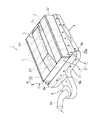
【図1】本発明の一実施形態によるバッテリ冷却装置の斜視図である。
【図2】上記バッテリ冷却装置の平面図である。
【図3】上記バッテリ冷却装置の断面図(図2のIII-III 線断面図) である。
【図4】上記バッテリ冷却装置のバッテリケースの分解斜視図である。
【図5】上記バッテリケースの断面側面図である。
【図6】従来の一般的なバッテリ冷却装置の斜視図である。
【図7】従来のバッテリ冷却装置の断面図である。
【符号の説明】
1 バッテリ冷却装置
2 バッテリ
3 バッテリケース
4 空気導入ダクト(空気導入通路)
4a 上流口
5 空気排出ダクト(空気排出通路)
5a 排出口
6 冷却ファン
7a 隔壁
7c 上壁
9 バッテリ収納室
25 空気分配ダクト(空気分配通路)[0001]
BACKGROUND OF THE INVENTION
The present invention relates to an electric vehicle in which wheels are driven to rotate by an electric motor that uses a battery as a power source, and more particularly to a battery cooling device that cools a battery with air during charging or the like.
[0002]
[Prior art]
2. Description of the Related Art In recent years, attention has been drawn to electric automobiles that run by rotating the wheels by an electric motor. In order to extend the mileage in such an electric vehicle, it is necessary to mount a large number of batteries. Recently, each battery is housed in a case, and the case is disposed under the floor between front and rear wheels. It is common.
[0003]
The battery needs to be charged moderately, but since the battery temperature rises during charging, the battery is cooled from the viewpoint of preventing performance deterioration due to abnormal temperature rise. As such a battery cooling device, conventionally, as shown in FIGS. 6 and 7, for example, a large number of
[0004]
In this cooling device, when the battery temperature exceeds a predetermined value, the
[0005]
[Problems to be solved by the invention]
However, the conventional battery cooling device employs a cooling structure based on a linear air flow in which cooling air sucked from the front wall of the battery case is discharged from the rear wall. And the wind speed may be different, and in some cases, the cooling of the battery may vary. For this reason, it is necessary to perform a time-consuming tuning operation for making the wind speed uniform.
[0006]
Moreover, in the said conventional apparatus, the structure which sucks out the cooling air in a battery case with a cooling fan is employ | adopted, For this reason, there exists a possibility that dust etc. may penetrate | invade in a battery case. For this reason, it is necessary to improve the sealing performance of the battery case, and there is a problem that the cost increases.
[0007]
The present invention has been made in view of the above-described conventional situation, and can provide a battery cooling device for an electric vehicle that can prevent variation in cooling of each battery and eliminate the need for troublesome tuning work and prevent dust from entering. It is intended to provide.
[0008]
[Means for Solving the Problems]
The present invention provides a battery cooling apparatus for an electric vehicle that introduces cooling air into a battery case containing a large number of batteries through an air introduction passage and discharges the cooling air to the outside through an air discharge passage. The battery case is divided into independent battery storage chambers by partitions formed at intervals in the longitudinal direction of the vehicle , and a cooling air inflow space and a cooling air outflow space are respectively provided on the lower side and upper side of the battery in each battery storage chamber. And a cooling air rising space is provided between the partition wall and the battery, and an air introduction passage for supplying cooling air to the cooling air inflow spaces of the battery storage chambers is connected to the left and right side walls of the battery case. together, air discharge to discharge to the outside in the vehicle width direction central portion of the upper wall from the cooling air outflow space of each battery storage chamber is taken out cooling air An air distribution passage that extends in the vehicle width direction and communicates with the upstream port of the left and right air introduction passages is provided on the front wall of the battery case, and a cooling fan is connected to the air distribution passage. It is characterized by that.
[0009]
[Effects of the invention]
The battery cooling device of the present invention drives the cooling fan when the battery temperature exceeds a predetermined value during charging or the like. The cooling air blown by the cooling fan is supplied to the lower side of each battery from the left and right air introduction passages through the air distribution passage, rises and merges while cooling each battery, and passes through the air discharge passage. It is discharged outside.
[0010]
According to the present invention, the air introduction passage is connected to the left and right side walls of the battery case, the air discharge passage is connected to the center portion of the upper wall, and the air distribution passage is provided at the upstream port of the left and right air introduction passages. Since the cooling fan is connected to the air, the air pressurized by the cooling fan is introduced from the left and right sides of the battery case, merged at the center of the case, and discharged upward. The distribution can be made uniform, and thus the blowing pressure can be evenly applied to each battery, and variations in battery cooling can be prevented. As a result, time-consuming tuning work can be eliminated and work efficiency can be improved.
[0011]
In the present invention, since the cooling air is blown into the battery case by the cooling fan, the inside of the battery case has a positive pressure, so that intrusion of dust and the like from the outside can be prevented. As a result, the battery case seal can be relaxed compared to the conventional suction type, and the cost can be reduced accordingly.
[0012]
DETAILED DESCRIPTION OF THE INVENTION
Hereinafter, embodiments of the present invention will be described with reference to the accompanying drawings.
FIGS. 1 to 5 are views for explaining a battery cooling device for an electric vehicle according to an embodiment of the present invention. FIGS. 1, 2, and 3 are a perspective view, a plan view, and a cross section of the battery cooling device, respectively. FIG. 4 is a sectional perspective view of the battery case, and FIG. 5 is a sectional side view of the main part of the battery case.
[0013]
In the figure, reference numeral 1 denotes a battery cooling device disposed under the floor between a front wheel and a rear wheel of an electric vehicle (not shown), which mainly includes a battery case 3 in which a large number of
[0014]
The battery case 3 is formed of an aluminum alloy extruded material, and includes a
[0015]
The
[0016]
Here, as shown in FIG. 5, the case
[0017]
Accordingly, the
[0018]
A plurality of mounting
[0019]
In each of the
[0020]
The left and
[0021]
A fixed
[0022]
The
[0023]
In this manner, in each
[0024]
The left and
[0025]
The
[0026]
An
[0027]
An
[0028]
Next, the effect of this embodiment is demonstrated.
The battery cooling device 1 according to the present embodiment is a controller that drives the cooling fan 6 when the battery temperature from a temperature sensor (not shown) disposed in the
[0029]
The cooling air pressurized by the cooling fan 6 branches left and right from the
[0030]
According to the present embodiment, the
[0031]
In particular, when a high-performance battery that has recently been attracting attention, such as a Ni-hydrogen battery, is employed, temperature control with higher accuracy than that of a general lead battery is required, and when such a high-performance battery is employed. It is valid.
[0032]
Moreover, in this embodiment, since the cooling air is blown into the battery case 3 whose pressure has been increased by the cooling fan 6, the inside of the battery case 3 has a positive pressure and can prevent entry of dust and the like from the outside. As a result, the battery case seal can be relaxed and the cost can be reduced as compared with the conventional suction type.
[Brief description of the drawings]
FIG. 1 is a perspective view of a battery cooling device according to an embodiment of the present invention.
FIG. 2 is a plan view of the battery cooling device.
3 is a cross-sectional view of the battery cooling device (a cross-sectional view taken along line III-III in FIG. 2).
FIG. 4 is an exploded perspective view of a battery case of the battery cooling device.
FIG. 5 is a cross-sectional side view of the battery case.
FIG. 6 is a perspective view of a conventional general battery cooling device.
FIG. 7 is a cross-sectional view of a conventional battery cooling device.
[Explanation of symbols]
DESCRIPTION OF SYMBOLS 1
5a Discharge port 6
Claims (1)
Priority Applications (1)
| Application Number | Priority Date | Filing Date | Title |
|---|---|---|---|
| JP29255099A JP3640846B2 (en) | 1999-10-14 | 1999-10-14 | Battery cooling device for electric vehicle |
Applications Claiming Priority (1)
| Application Number | Priority Date | Filing Date | Title |
|---|---|---|---|
| JP29255099A JP3640846B2 (en) | 1999-10-14 | 1999-10-14 | Battery cooling device for electric vehicle |
Publications (2)
| Publication Number | Publication Date |
|---|---|
| JP2001105894A JP2001105894A (en) | 2001-04-17 |
| JP3640846B2 true JP3640846B2 (en) | 2005-04-20 |
Family
ID=17783229
Family Applications (1)
| Application Number | Title | Priority Date | Filing Date |
|---|---|---|---|
| JP29255099A Expired - Fee Related JP3640846B2 (en) | 1999-10-14 | 1999-10-14 | Battery cooling device for electric vehicle |
Country Status (1)
| Country | Link |
|---|---|
| JP (1) | JP3640846B2 (en) |
Cited By (2)
| Publication number | Priority date | Publication date | Assignee | Title |
|---|---|---|---|---|
| JP2009119936A (en) * | 2007-11-12 | 2009-06-04 | Honda Motor Co Ltd | Battery cooling device for vehicle |
| US7905308B2 (en) | 2007-11-12 | 2011-03-15 | Honda Motor Co., Ltd. | Vehicle battery cooling device |
Families Citing this family (24)
| Publication number | Priority date | Publication date | Assignee | Title |
|---|---|---|---|---|
| JP4547747B2 (en) * | 1999-12-09 | 2010-09-22 | トヨタ自動車株式会社 | In-vehicle battery pack cooling system |
| KR100383975B1 (en) * | 2000-12-21 | 2003-05-14 | 현대자동차주식회사 | battery tray of electric vehicle |
| KR100428339B1 (en) * | 2001-10-29 | 2004-04-28 | 현대자동차주식회사 | Cooling system for battery of electric vehicle |
| JP4242665B2 (en) | 2002-05-13 | 2009-03-25 | パナソニック株式会社 | Battery pack cooling device and secondary battery |
| KR20030088941A (en) * | 2002-05-15 | 2003-11-21 | 현대자동차주식회사 | Battery pack assembly for electric automobile |
| JP4374925B2 (en) * | 2003-06-26 | 2009-12-02 | トヨタ自動車株式会社 | Battery pack cooling structure |
| JP5060016B2 (en) * | 2004-01-07 | 2012-10-31 | トヨタ自動車株式会社 | Battery mounting structure |
| KR100648704B1 (en) * | 2005-07-29 | 2006-11-23 | 삼성에스디아이 주식회사 | Secondary battery module |
| JP5009096B2 (en) * | 2007-08-29 | 2012-08-22 | 本田技研工業株式会社 | Electric car |
| DE102007044461A1 (en) * | 2007-09-11 | 2009-03-12 | Daimler Ag | Heat exchanger unit and electrochemical energy storage with a heat exchanger unit |
| JP5186955B2 (en) * | 2008-03-10 | 2013-04-24 | トヨタ自動車株式会社 | Power storage device |
| DE102008051085A1 (en) | 2008-10-09 | 2010-04-15 | Dr.Ing.H.C.F.Porsche Aktiengesellschaft | battery assembly |
| JP5185788B2 (en) * | 2008-11-26 | 2013-04-17 | 本田技研工業株式会社 | Air introduction device |
| JP2012096715A (en) * | 2010-11-04 | 2012-05-24 | Suzuki Motor Corp | Cooling duct structure for battery unit |
| JP5482697B2 (en) * | 2011-03-16 | 2014-05-07 | マツダ株式会社 | Air conditioning structure for vehicle battery unit |
| KR101475737B1 (en) | 2012-02-07 | 2014-12-24 | 주식회사 엘지화학 | Battery Pack of Novel Air Cooling Structure |
| JP5962163B2 (en) * | 2012-04-13 | 2016-08-03 | マツダ株式会社 | Air conditioning structure for vehicle battery unit |
| JP6340326B2 (en) * | 2015-01-28 | 2018-06-06 | 日立建機株式会社 | Construction machinery |
| WO2016125389A1 (en) * | 2015-02-05 | 2016-08-11 | 本田技研工業株式会社 | Power source device for a vehicle |
| CN106129530B (en) * | 2016-08-18 | 2018-08-28 | 系统电子科技(镇江)有限公司 | A kind of novel battery packet air cooling system |
| JP7413676B2 (en) | 2019-08-08 | 2024-01-16 | スズキ株式会社 | air circulation equipment |
| JP7314705B2 (en) | 2019-08-08 | 2023-07-26 | スズキ株式会社 | vehicle battery pack |
| CN110936802A (en) * | 2019-11-25 | 2020-03-31 | 河南美力达汽车有限公司 | Protection type new energy automobile |
| CN116885330B (en) * | 2023-09-08 | 2023-12-08 | 深圳市杰成镍钴新能源科技有限公司 | Battery discharging device, cooling control method thereof and discharging assembly |
-
1999
- 1999-10-14 JP JP29255099A patent/JP3640846B2/en not_active Expired - Fee Related
Cited By (3)
| Publication number | Priority date | Publication date | Assignee | Title |
|---|---|---|---|---|
| JP2009119936A (en) * | 2007-11-12 | 2009-06-04 | Honda Motor Co Ltd | Battery cooling device for vehicle |
| JP4509170B2 (en) * | 2007-11-12 | 2010-07-21 | 本田技研工業株式会社 | Battery cooling device for vehicle |
| US7905308B2 (en) | 2007-11-12 | 2011-03-15 | Honda Motor Co., Ltd. | Vehicle battery cooling device |
Also Published As
| Publication number | Publication date |
|---|---|
| JP2001105894A (en) | 2001-04-17 |
Similar Documents
| Publication | Publication Date | Title |
|---|---|---|
| JP3640846B2 (en) | Battery cooling device for electric vehicle | |
| JP4385020B2 (en) | Vehicle power supply | |
| JP3229637B2 (en) | Battery cooling structure for electric vehicles | |
| JP5015649B2 (en) | Battery and electrical equipment cooling structure | |
| JP3554475B2 (en) | Cooling structure of electric parts in electric vehicle | |
| US4135593A (en) | Electrically driven vehicles | |
| US20090120620A1 (en) | Vehicle battery cooling device | |
| KR101283229B1 (en) | COOLING STRUCTURE FOR Environmental-friendly VEHICLE | |
| JP6044244B2 (en) | Battery pack for vehicles | |
| JPH11180168A (en) | Cooling structure of battery and electric parts for electric vehicle | |
| JP6573680B2 (en) | vehicle | |
| JP2006318820A (en) | Cooling structure of battery box | |
| JP5186955B2 (en) | Power storage device | |
| JP2000100481A (en) | Battery box for electric vehicle | |
| JP7055642B2 (en) | vehicle | |
| CN110861486A (en) | Duct structure for vehicle | |
| JP2005019231A (en) | Cooling structure of battery pack | |
| JP5822281B2 (en) | Battery pack for electric vehicles | |
| JPS5977924A (en) | Cooler for v-belt change gear of autobicycle | |
| JP6057826B2 (en) | Power storage device | |
| KR100453274B1 (en) | Method of manufacturing ventilating device and the ventilating device | |
| JPH07215070A (en) | Battery device for electric vehicle | |
| CN110861487A (en) | Duct structure for vehicle | |
| KR100911989B1 (en) | A Cooling Apparatus of Blower Motor for an Air Conditioning System of a Car | |
| JP6232776B2 (en) | Electric component pack cooling system |
Legal Events
| Date | Code | Title | Description |
|---|---|---|---|
| A977 | Report on retrieval |
Free format text: JAPANESE INTERMEDIATE CODE: A971007 Effective date: 20040830 |
|
| A131 | Notification of reasons for refusal |
Free format text: JAPANESE INTERMEDIATE CODE: A131 Effective date: 20040921 |
|
| A521 | Written amendment |
Free format text: JAPANESE INTERMEDIATE CODE: A523 Effective date: 20041117 |
|
| TRDD | Decision of grant or rejection written | ||
| A01 | Written decision to grant a patent or to grant a registration (utility model) |
Free format text: JAPANESE INTERMEDIATE CODE: A01 Effective date: 20050118 |
|
| A61 | First payment of annual fees (during grant procedure) |
Free format text: JAPANESE INTERMEDIATE CODE: A61 Effective date: 20050119 |
|
| R150 | Certificate of patent or registration of utility model |
Free format text: JAPANESE INTERMEDIATE CODE: R150 |
|
| FPAY | Renewal fee payment (event date is renewal date of database) |
Free format text: PAYMENT UNTIL: 20080128 Year of fee payment: 3 |
|
| FPAY | Renewal fee payment (event date is renewal date of database) |
Free format text: PAYMENT UNTIL: 20100128 Year of fee payment: 5 |
|
| FPAY | Renewal fee payment (event date is renewal date of database) |
Free format text: PAYMENT UNTIL: 20100128 Year of fee payment: 5 |
|
| FPAY | Renewal fee payment (event date is renewal date of database) |
Free format text: PAYMENT UNTIL: 20120128 Year of fee payment: 7 |
|
| FPAY | Renewal fee payment (event date is renewal date of database) |
Free format text: PAYMENT UNTIL: 20140128 Year of fee payment: 9 |
|
| LAPS | Cancellation because of no payment of annual fees |