JP3633884B2 - Playback image transmission device - Google Patents
Playback image transmission device Download PDFInfo
- Publication number
- JP3633884B2 JP3633884B2 JP2001166818A JP2001166818A JP3633884B2 JP 3633884 B2 JP3633884 B2 JP 3633884B2 JP 2001166818 A JP2001166818 A JP 2001166818A JP 2001166818 A JP2001166818 A JP 2001166818A JP 3633884 B2 JP3633884 B2 JP 3633884B2
- Authority
- JP
- Japan
- Prior art keywords
- reproduction
- image
- data
- pes
- decoding
- Prior art date
- Legal status (The legal status is an assumption and is not a legal conclusion. Google has not performed a legal analysis and makes no representation as to the accuracy of the status listed.)
- Expired - Fee Related
Links
Images


Classifications
-
- H—ELECTRICITY
- H04—ELECTRIC COMMUNICATION TECHNIQUE
- H04N—PICTORIAL COMMUNICATION, e.g. TELEVISION
- H04N21/00—Selective content distribution, e.g. interactive television or video on demand [VOD]
- H04N21/40—Client devices specifically adapted for the reception of or interaction with content, e.g. set-top-box [STB]; Operations thereof
- H04N21/43—Processing of content or additional data, e.g. demultiplexing additional data from a digital video stream; Elementary client operations, e.g. monitoring of home network or synchronising decoder's clock; Client middleware
- H04N21/436—Interfacing a local distribution network, e.g. communicating with another STB or one or more peripheral devices inside the home
- H04N21/4363—Adapting the video or multiplex stream to a specific local network, e.g. a IEEE 1394 or Bluetooth® network
- H04N21/43632—Adapting the video or multiplex stream to a specific local network, e.g. a IEEE 1394 or Bluetooth® network involving a wired protocol, e.g. IEEE 1394
-
- H—ELECTRICITY
- H04—ELECTRIC COMMUNICATION TECHNIQUE
- H04N—PICTORIAL COMMUNICATION, e.g. TELEVISION
- H04N5/00—Details of television systems
- H04N5/76—Television signal recording
- H04N5/78—Television signal recording using magnetic recording
- H04N5/782—Television signal recording using magnetic recording on tape
- H04N5/783—Adaptations for reproducing at a rate different from the recording rate
-
- H—ELECTRICITY
- H04—ELECTRIC COMMUNICATION TECHNIQUE
- H04N—PICTORIAL COMMUNICATION, e.g. TELEVISION
- H04N5/00—Details of television systems
- H04N5/76—Television signal recording
- H04N5/765—Interface circuits between an apparatus for recording and another apparatus
- H04N5/775—Interface circuits between an apparatus for recording and another apparatus between a recording apparatus and a television receiver
Description
【0001】
【発明の属する技術分野】
本発明は、送信機が持つハードディスクに蓄積されたMPEG画像を、IEEE1394のような双方向ネットワークを介して受信装置に送信する画像再生システムに関し、特に、受信装置においてP又はBピクチャを使った逆再生画像を生成するものに関するものである。
【0002】
【従来の技術】
近年、ネットワークの高速化と、ハードディスクの大容量化により、MPEG等で記録したデジタル画像をハードディスクに蓄積し、ネットワーク経由で受信機に送信するシステムが出てきた。この映像ネットワークシステムでは、IEEE1394の高速ネットワークが使用されており、そのネットワークを使用してハードディスクを持つ蓄積装置と映像を受信再生する再生装置とが接続されている。
【0003】
IEEE1394は、一定時間以内に転送するデータ量を保証するアイソクロノス(isochronous)転送機能を有している。isochronous転送は、一定期間に転送するデータ量が保証されているため、リアルタイム性を要求される映像や音声の伝送に適しており、BSデジタル放送のSTBや、デジタルVCR装置に数多く搭載されている。
【0004】
また、上記IEEE1394は、データやコマンド転送を行うために、アシンクロナス(asynchronous)転送を持っている。このasynchronous転送は、データを送りたい時にバスの使用権を獲得して送信するというスタイルの非同期転送であり、一定の期間の間に転送するデータ転送量が保証されていない。
【0005】
現在、IEEE1394はデジタルVCR協議会のDVB(欧州デジタル放送)やIEEE1394T.A.(トレードアソシエーション)などで詳細なコマンドが取り決められている。特にIEEE1394T.A.では、MPEGトランスポートストリームをIEEE1394上で伝送するための方式や、ハードディスクを使ったデジタルVCRを制御するためのコマンド等が策定されている。これらのコマンドはasynchronous転送を用いて転送される。
【0006】
しかしながら、IEEE1394においては、asynchronous転送、isochronous転送の順番にパケットを送出するようにしても、ネットワーク上においてasynchronous転送、isochronous転送の順番でパケットを送信するという保証が無い。すなわちasynchronous転送、isochronous転送の順番で、IEEE1394のパケット送信装置に対してパケットを送出しても、IEEE1394ネットワーク上では、isochronous転送、asynchronous転送の順番でパケットを送出する場合がある。
一方、MPEG画像で、Bピクチャ(双方向予測符号化画像)やPピクチャ(フレーム間順方向予測符号化画像)を使った逆再生画像を生成する場合、ピクチャ毎にデコードした画像の表示を変更しなければならない。
【0007】
図3は、Bピクチャ、Pピクチャを使ったMPEGデコード装置の構成を示している。デコードするMPEG画像入力3aは、MPEGデコード装置31に入力され、MPEGの文法に準拠したデコードが行われる。32は、MPEG画像をデコードするために必要な参照画像を蓄積するメモリで、ここにはMPEG画像デコード時の参照画像が格納される。MPEGデコード装置31でデコードされたMPEG画像は、フレームメモリ33に蓄積され、フレームメモリ33の画像は、モニタ34に表示される。
【0008】
ここで、P,Bピクチャを使った逆再生の方法について述べる。図4は、P、Bピクチャを使った順方向再生の方法を示している。順方向の再生時では、B0、I1、B2、P3、B4、I5、B6,P7と表示するために、MPEGデコード装置31に対して、I1,B0,P3,B2、I5,B4,P7,B6の順番に画像が入力される。するとMPEGデコード装置31は、参照画像メモリ32に図4で示す形でBピクチャをデコードするのに必要な参照画像を蓄積する。ここで、Iで始まる画像はIピクチャであり、他の参照画像を必要としないで映像をデコードすることができる。Pで始まる画像はPピクチャであり、デコードするためには、自分自身よりも1つ前のI、又はPピクチャから前方予測する必要がある。Bで始まる画像はBピクチャで、デコードするためには、特に指定の無い限り、ひとつ前のI、又はPピクチャからの前方予測と、ひとつ後ろのI、又はPピクチャからの後方予測とが必要である。
【0009】
MPEGデコード装置31でデコードされた画像は、フレームメモリ33にB0、I1、B2、P3、B4、I5、B6,P7の順に蓄積され、同じ順番で、モニタ34に表示される。このときスイッチ36は常に画像を通す状態である。
【0010】
図5は、P、Bピクチャを使った逆方向再生の方法を示している。図4で示された画像をB4、P3,B2、I1の順番で逆再生する方法を示す。B4の画像のデコードには、P3とI5の参照画像が必要である。しかし、P3の参照画像を作るためには、さらに前方のI1のピクチャが必要である。すなわちB4のピクチャを生成するには、I1,P3,I5、B4の4枚のピクチャが必要になる。同様に、P3の画像のデコードにはI1、P3のピクチャが必要であり、B2のピクチャのデコードにはI1,P3,B2のピクチャが必要である。I1ピクチャは、デコードするために他のピクチャを必要とはしない。
【0011】
ここでB4のピクチャをデコードする場合、B4のピクチャ以外にもI1,P3,I5のピクチャをデコードしなければならない。そのため、デコードされたI1,P3,I5のピクチャは参照画像メモリ32に蓄積されるが、フレームメモリ33に蓄積されてはならない。そのために図3の表示制御部35を使って、フレームメモリ33の出力のスイッチ36を制御し、ピクチャB4だけを表示するようにする。表示制御部35の生成するコマンドは、MPEGデコード装置31でデコードを行うが、画像表示は行わないというコマンド5Bと、MPEGデコード装置31でデコードを行い、画像表示も行うというコマンド5Aを図5の生成コマンドのように生成し、フレームメモリ33の蓄積を制御できるようにスイッチ36の制御を行わなければならない。他のピクチャも同様である。なお、B,Pピクチャを使わない逆方向再生以外では、コマンドは全て5Bである。
このようにMPEG画像の逆再生の時は、デコードは行うが、表示は行わないという制御を、ピクチャ毎に行う機能を付与することにより、P,Bピクチャを使った逆再生画像を生成することが可能になる。
【0012】
図2は、従来の画像伝送装置を示している。同図において、21は送信装置であり、22は蓄積装置であり、本例ではハードディスクを示しており、ハードディスクにはMPEGトランスポートストリームが任意の形式で記録されている。23はIEEE1394送受信手段、24はハードディスク制御手段である。
【0013】
また、25は再生装置であり、26はIEEE1394送受信手段、27はコマンド生成手段、28は画像再生手段である。同図において、蓄積装置22には、MPEGトランスポートストリーム6aの形でMPEG画像が記録されている。受信機25のコマンド生成手段27が、蓄積装置22に蓄積されたMPEGトランスポートストリーム6aを再生するための再生コマンド2aを生成し、IEEE1394送受信手段26に送る。再生コマンド2aは、IEEE1394T.A.(トレードアソシエーション)のコマンドに準拠しており、再生、早送り、逆再生、再生停止等の再生状態を指定するが、ピクチャ毎の再生制御は行わない。
【0014】
IEEE1394送受信手段26は、再生コマンド2aをIEEE1394上のasynchronousパケットに変換して、IEEE1394ネットワーク2bで伝送し、IEEE1394送受信手段23に送る。IEEE1394送受信手段23は、伝送されたasynchronousパケットから再生コマンド2aを取りだし、ハードディスク制御手段24に送出する。ハードディスク制御手段24は、再生コマンド2aに対応するMPEG画像を蓄積装置22の内部に記録されているMPEGトランスポートストリーム6aを読み出し、IEEE1394送受信手段23に送信する。
【0015】
IEEE1394送受信手段23は蓄積装置22から読み出されたMPEGトランスポートストリーム6aをisochronousパケットに変換してIEEE1394ネットワーク2bに送出する。送出されたisochronousパケットは、IEEE1394送受信手段26において、MPEGトランスポートストリーム6aに変換され画像再生手段28に送信される。図3の構成は、表示制御部35以外は、画像再生手段28に含まれている。図3の表示制御部35によるデコード制御信号は、蓄積装置22から読み出すピクチャに同期して生成するため、ハードディスク制御手段24に含まれる。
【0016】
図6はIEEE1394送受信手段23、26の構成を示している。再生コマンド2aは、asynchronous転送手段61で非同期転送のパケットに変換され、IEEE1394リンク層63、IEEE1394物理層64を介して、IEEE1394ネットワーク2b上で送受信される。MPEGトランスポートストリーム6aは、isochronous転送手段62でIEEE1394のアイソクロナスパケットに変換され、IEEE1394リンク層63、IEEE1394物理層64を介して、IEEE1394ネットワーク2b上で送受信される。MPEGトランスポートストリーム送受信手段の変換方法と送受信方法は、IEEE1394上で策定されている。またIEEE1394リンク層63、IEEE1394物理層64は、IEEE1394上で規格化されたものである。
【0017】
図7は、MPEGトランスポートストリームの構成を示している。図7において、71はエレメンタリストリームと呼ばれるビット列で、映像や音声等の情報が記されている。画像では、多くの場合MPEGビデオ圧縮されたビット列が治められている。そのビット列はISO/IEC13818−2で規定されている方式に従っている。この映像のエレメンタリストリーム71の中には、Sequence_headerが記述されていることがあり、その中には、画像の圧縮方式、SD画像とHD画像の識別、構成、ピクチャ間の出力間隔等の情報が記載されている。エレメンタリストリーム71にISO/IEC13818−1で規定されたPESヘッダを付けたものをPESストリームと呼ぶ。
【0018】
そして、上記PESストリームを任意の大きさに分割後、ISO/IEC13818−1で規定されたヘッダを付加し、188byte長の固定パケットにし、更に様々な情報を付加し、多チャンネル化したものがMPEGトランスポートストリームである。
ここで、MPEG画像とは、ISO/IEC13818−2、またはISO/IEC11172−2で規定された信号をエレメンタリストリームとするISO/IEC13818−1で規定されたMPEGトランスポートストリームのことを指すものとする。
【0019】
図2で示された従来の構成において、ハードディスクに蓄積された画像を順方向再生、停止、Iピクチャのみの逆再生を行う場合、図2、図3、図4で示した通り、再生コマンド2aをasynchronous転送で送受信した後、isochronous転送を開始すればよい。asynchronous転送の送受信が終了したことを確認してからisochronous転送をしても問題なく画像を再生することができる。
【0020】
一方、P,Bピクチャを使った逆再生を行う場合、ピクチャ毎にデコードの制御信号を生成しなければならない。このデコードの制御信号は、GOP(Group Of Picture)の構成に依存するため、図2のハードディスク制御手段24に含まれる。そのため、ハードディスク制御手段24の中の表示制御部35が生成したデコード制御信号は、IEEE1394ネットワーク2bを通じて、再生装置25、画像再生手段28に送信されなければならない。この表示制御部35が生成したデコード制御信号は、蓄積装置22から読み出される画像に同期し、且つコマンド信号であるため、IEEE1394ネットワーク2bにおいてasynchronous転送で送信しなければならない。
すなわち、isochronous転送で転送されるMPEGピクチャと、表示制御部35が生成したデコード制御信号のasynchronous転送とが同期して、IEEE1394ネットワーク2bの上を転送されなければならない。
【0021】
このために、IEEE1394送受信手段23に、表示制御部35が生成したデコード制御信号のasynchronousパケットをasynchronous転送手段61に入力した後、isochronous転送で転送されるMPEGピクチャをisochronous転送手段62に送信した場合、IEEE1394のリンク層63は、先に入力したasynchronous転送を先に行わず、後に入力したisochronous転送を先に行う場合がある。なぜならIEEE1394の規格において、asynchronous転送とisochronous転送の送信順番が保証されていないからである。
【0022】
仮にasynchronous転送、isochronous転送の順に送信しても、受信後、送信順番が反転する可能性がある。asynchronous転送、isochronous転送の送信順を保証するために、asynchronous転送の完了を確認してから、つまり、この間、isochronous転送を停止してasynchronous転送を行い、その後、isochronous転送手段62にてMPEGピクチャを送信した場合、asynchronous転送の伝送帯域が保証されていないため、転送速度がasynchronous転送に律速されてしまい、isochronous転送の帯域が保証されなくなる可能性がある。再生、停止といったコマンド自身は、コマンド前後の伝送帯域を考慮しなくてもよいが、ピクチャ毎の制御信号に関しては、コマンドの前後の伝送帯域も保証しなければならない。
すなわち従来の構成において、MPEG画像の逆再生を行うために、ピクチャに同期したデコード制御信号を送受信することができないという課題があった。
【0023】
【発明が解決しようとする課題】
従来の逆再生画像生成装置は以上のように構成されており、IEEE1394ネットワークを介して逆再生画像を生成する装置と、逆再生画像をデコードする装置とが接続されている場合、asynchronous転送とisochronous転送との転送順がIEEE1394上で保証されないため、isochronous転送で転送されるMPEGピクチャと、asynchronous転送で転送される制御信号との同期がとれず、逆再生画像をデコードすることができないという問題点があった。
【0024】
本発明はかかる問題に鑑みてなされたものであって、再生装置側で受信したMPEGピクチャとその制御信号の同期を保証し、P,Bピクチャを使ったMPEGの逆再生を可能とする再生画像伝送装置を提供することを目的とする。
【0025】
【課題を解決するための手段】
本発明の請求項1にかかる再生画像伝送装置は、帯域が保証されたisochronous転送と、非同期にて転送が行われるasynchronous転送の2つの転送モードを有するIEEE1394インターフェースにて構成された双方向ネットワーク間で再生画像を伝送する再生画像伝送装置であって、再生画像データを蓄積するデータ蓄積手段と、上記再生画像データと、該再生画像データの再生制御を行うための再生制御パラメータとを上記isochronous転送にて伝送するよう上記データ蓄積手段より読み出した再生画像データを、自身の再生制御を行うためのタイムスタンプ情報が加工や再生制御により破綻しないように加工するデータ加工手段とを備えたものである。
【0026】
また、本発明の請求項2にかかる再生画像伝送装置は、請求項1記載の再生画像伝送装置において、上記再生画像データがMPEGトランスポートストリームであり、上記再生制御パラメータは、上記MPEGトランスポートストリームのデコード及び表示処理の指示に関するものである。
【0027】
また、本発明の請求項3にかかる再生画像伝送装置は、請求項2記載の再生画像伝送装置において、上記データ加工手段は、デコードと表示を行う、デコードは行うが表示は行わない、デコードは行わず表示は前回の画像をそのまま保持する、デコードは行わず、画像の表示も行わないという再生制御パラメータをISO/IEC13818−1にて規定されるPES_header中のDSMのtrick_mode_controlのフラグの3’b101から3’b111までの領域とそれに続く5ビットに割り当てるものである。
【0028】
また、本発明の請求項4にかかる再生画像伝送装置は、請求項3記載の再生画像伝送装置において、上記データ加工手段は、デコードと表示を行うという再生制御パラメータに、ISO/IEC13818−1にて規定されるPES_header中のDSMのtrick_mode_control=3’b100と、rep_cntrl≠5’b00000を割り当て、デコードは行うが表示は行わないをPES_header中のDSMのtrick_mode_control=3’b100と、rep_cntrl=5’b00000を割り当てるものである。
【0029】
また、本発明の請求項5にかかる再生画像伝送装置は、請求項2記載の再生画像伝送装置において、上記データ加工手段は、デコードと表示を行う、デコードは行うが表示は行わない、デコードは行わず表示は前回の画像をそのまま保持する、デコードは行わず、画像の表示も行わないという制御信号をISO/IEC13818−1にて規定されるPES_header中のPES_private_data、又はPES_extension_field_lengthに記述するものである。
【0030】
また、本発明の請求項6にかかる再生画像伝送装置は、請求項2記載の再生画像伝送装置において、上記データ蓄積手段から読み出された再生画像データの読み出し符号量を監視し、該符号量が所定値以下になると、再生装置におけるデコーダのバッファに蓄積されたデータが復号化処理に必要量以下となったことを示すアンダーフロー発生信号を発生する符号量監視手段と、上記符号量監視手段から発生されたアンダーフロー発生信号を受けて、ダミーパケットを発生するダミーデータ生成手段と、上記データ加工手段で加工されたMPEG transport streamの間に上記ダミーパケットを埋め込むセレクタ手段とを備えたものである。
【0031】
また、本発明の請求項7にかかる再生画像伝送装置は、帯域が保証されたisochronous転送と、非同期にて転送が行われるasynchronous転送の2つの転送モードを有するIEEE1394インターフェースにて構成された双方向ネットワーク間で再生画像を伝送する再生画像伝送装置であって、上記再生画像データ、及び該再生画像データを逆再生する際に必要な再生制御パラメータとを蓄積するデータ蓄積手段と、上記再生画像データと、上記再生制御パラメータとを上記isochronous転送にて伝送するものである。
【0032】
また、本発明の請求項8にかかる再生画像伝送装置は、請求項2記載の再生画像伝送装置において、上記データ加工手段は、デコードと表示を行う、デコードは行うが表示は行わない、デコードは行わず表示は前回の画像をそのまま保持する、デコードは行わず、画像の表示も行わないという再生制御パラメータをISO/IEC13818−2にて規定されるPicture_Header中のTemporal_Referenceに記述するものである。
【0033】
【発明の実施の形態】
(実施の形態1)
図1は、本発明の実施の形態1にかかる逆再生画像生成装置である画像伝送装置の構成を示すブロック図である。同図において、11は送信装置であり、データを蓄積する蓄積装置12、データ送受信手段であるIEEE1394送受信手段13、上記蓄積手段12より所定のデータを読み出す読み出し手段14、蓄積装置12に蓄積されたMPEG transport stream1eを加工するMPEG transport stream加工手段15とから構成されている。
【0034】
また、16は再生装置であり、17はデータ送受信手段であるIEEE1394送受信手段、18はIEEE1394T.A.(トレードアソシエーション)に準拠したコマンドを生成するコマンド生成手段、19は入力されたMPEG transport stream 1gを再生して表示を行うMPEG画像再生手段、1cはMPEG画像再生手段19を制御する再生制御手段である。
【0035】
上記送信装置11と再生装置16とはIEEE1394ネットワーク1bで接続されている。上記蓄積手段12はハードディスク等のランダムアクセス可能なデバイスであり、MPEGトランスポートストリームが任意の形式で記録されている。このMPEG画像は、ISO/IEC 13818−2、又はISO/IEC 11172−2で規定された画像であり、MPEG transport streamとは、前記MPEG画像をエレメンタリストリームとして含む、ISO/IEC 13818−1で規定されたstreamである。
【0036】
以下に動作について図1を参照して説明する。従来例と同様、同図において図2と同様に、コマンド生成手段18は、IEEE1394T.A.(トレードアソシエーション)に準拠した再生コマンド1aをIEEE1394送受信手段17に送信する。IEEE1394送受信手段17は、IEEE1394ネットワーク1bと接続されており、再生コマンド1aをIEEE1394T.A.(トレードアソシエーション)で定められたフォーマットasynchronousパケットに変換し、IEEE1394ネットワーク1bに送信され、IEEE1394ネットワーク1bを介して送信装置11中のIEEE1394送受信手段13に送信される。
【0037】
IEEE1394送受信手段13、17の構成は図6で示されたものと同一であるのでここではその詳細については省略する。
IEEE1394送受信手段13は、受信したasynchronousパケットから再生コマンド1aを取り出し、読み出し手段14に送付する。
【0038】
読み出し手段14は、蓄積装置12に蓄積されたMPEG transport streamから再生コマンド1aに適したピクチャを選択し、MPEG transport stream1eとしてMPEG transport stream加工手段15に送付される。読み出し手段14が選択するピクチャは、例えば、順方向再生の場合、図4に示すMPEGデコード装置31への入力順のようにI1、B0,P3、B2・・・と選択される。同様にP,Bピクチャを使った逆方向再生では、図5で示すMPEGデコード装置31への入力順のようにB4ピクチャの表示のために、I1,P3,I5,B4の順に4枚のピクチャを選択して出力する。
【0039】
ここで、MPEG transport stream加工手段15に送付されたMPEG transport stream1eは、P,Bピクチャを使った逆再生時に、そのまま出力すると、目的の画像とは異なった画像が表示されてしまう。
そこで、MPEG transport stream加工手段15は、MPEG transport streamに対し、再生制御手段1cを制御するための信号を付与する。再生制御手段1cを制御する信号を付与された加工されたMPEG transport stream 1fは、IEEE1394送受信手段13に送付される。
【0040】
図8はMPEG transport stream加工手段15の構成を示しており、PES(Packetized Elementary Stream)_header検出手段81、DSM(Digital Storage Media)位置検出手段82、コマンド判定手段83、DSM書き換え手段84から構成されている。
【0041】
読み出されたMPEG transport stream1eは、PES_header検出手段81、DSM位置検出手段82、DSM書き換え手段84にそれぞれ入力される。PES_header検出手段81は、入力されたMPEG transport stream1eから、PES_headerを検出し、PES_header認識信号85をDSM位置検出手段に送出する。
【0042】
図9はPESの構成を示す。図9のPESの構成は、ISO/IEC 13818−1で規定されている。なお、本実施の形態において、1個のPESに含まれるMPEG画像は1ピクチャであるものとする。図8において、DSM位置検出手段82は、PES_header認識信号85を受けると、DSM_trick_mode_flagが立っている場合は、trick_mode_controlとDSM_dataの位置と次のPESのPES_CRC_flagを、DSM認識信号86としてDSM書き換え手段84に送信し、一方、DSM_trick_mode_flagが立っていない場合は、PES_packet_length、DSM_trick_mode_flag、PES_header_data_lengthと次のPESのPES_CRC_flagをDSM認識信号86としてDSM書き換え手段84に送信する。コマンド判定手段83は入力された再生コマンド1aを判定して、逆再生の場合に逆再生信号87を、DSM書き換え手段84に送付する。
【0043】
DSM書き換え手段84は、DSM_trick_mode_flagが立っている場合は、入力されるMPEG transport stream 1eに対して、trick_mode_controlとDSM_dataの書き換えを行う。さらにそのPESの書き換え後のCRCを計算し、次のPESにおいてPES_CRC_flagが立っている場合は、PES_CRCの書き換えを行い、MPEG transport stream 1fとしてIEEE送受信手段13に送出される。
【0044】
DSM書き換え手段84は、DSM_trick_mode_flagが立っていない場合は、PES_packet_lengthを0に書き換える又は、1を加算し、DSM_trick_mode_flagのフラグを立て、PES_header_data_lengthに1を加算し、trick_mode_controlとDSM_dataの位置に、これらのデータを挿入する。DSM書き換え手段84は更にそのPESの書き換え後のCRCを計算し、次のPESにおいてPES_CRC_flagが立っている場合は、PES_CRCの書き換えを行い、加工されたMPEG transport stream1fとしてIEEE1394送受信手段13に送出される。
【0045】
次に上記DSM書き換え手段84で書き換えられるtrick_mode_controlとDSM_dataの書き換え内容の実例を、図10に示す。図10において、コマンドAはMPEG画像のデコードを行い、デコードされた画像を表示するコマンド記述を示しており、図5のコマンド5Aと同様である。コマンドBはMPEG画像のデコードを行い、デコードされた画像の表示は行わずに、時間的に前に表示されたデコード画像をそのまま表示し続けるコマンド記述を示しており、図5のコマンド5Bと同様である。コマンドCは入力されたMPEG画像のデコードを行わず、前に表示されたデコード画像をクリアするコマンド記述を示している。コマンドDは入力されたMPEG画像のデコードを行わず、時間的に前に表示されたデコード画像をそのまま表示し続けるコマンド記述を示している。
【0046】
MPEG transport stream加工手段15は、図5における表示制御部35で生成するコマンドを、PES_headerに付与する。図5における5Bで示すコマンドが、図10におけるコマンドBを示しており、図5における5Aで示すコマンドが図10におけるコマンドAを示すように、MPEG transport stream加工手段15は加工を行う。図1において、IEEE1394送受信手段13に送付された、MPEG transport stream 1fは、IEEE1394送受信手段13でisochronousパケットに変換され、IEEE1394ネットワーク1bに送信される。
【0047】
IEEE1394ネットワーク1bに送信されたisochronousパケットは、再生装置16に送信され、IEEE1394送受信手段17で、isochronousパケットを MPEG transport stream 1gに変換し、MPEG画像再生手段19、再生制御手段1cに送信する。再生制御手段1cは、MPEG transport stream 1gからMPEG transport stream加工手段15で加工された図10で示すコマンドを取り出し、ピクチャ制御信号1hとして、MPEG画像再生手段19に送信する。
【0048】
図11に、再生制御手段1cの構成例を示す。図11において、入力されたMPEG transport stream 1gは、コマンド抽出手段111とPicture_header検出手段112に送出される。コマンド抽出手段111はMPEG transport stream 1gから、MPEG transport stream加工手段15で加工された図10で示すコマンドを取り出し、ピクチャ制御信号114を同期出力手段113に送付する。
【0049】
Picture_header検出手段112は、MPEG transport stream 1gから、Picture_headerを抽出すると、Picture_headerを検出したことを示す、ピクチャ同期信号115を同期出力手段113に出力する。同期出力手段113はピクチャ同期信号115に合わせて、ピクチャ制御信号114を、ピクチャ制御信号1hとして出力する。図12は、再生制御手段1cに入力するMPEG transport stream1gと、出力するピクチャ制御信号1hとの関係を示している。図12において、121は、入力するMPEG transport stream 1gの中で、PES_headerを持つMPEG transport stream パケットである。122は、入力するMPEG transport stream 1gの中で、ピクチャ制御信号114を含むMPEG transport streamのパケットである。123は、入力するMPEG transport stream 1gの中で、Picture_headerを含むパケットである。121、122、123のパケットは、同一パケットになる場合があるが、PES_header、ピクチャ制御信号、Picture_headerはこの順番で入力される。
【0050】
Picture_header検出手段112は123のパケットからPicture_headerを検出すると、ピクチャ同期信号115を生成する。パケット122から抽出されたピクチャ制御信号114は、パケット123から生成されたピクチャ同期信号115に同期して、ピクチャ制御信号1hを送出する。
MPEG画像再生手段19は、入力されたMPEG transport stream 1gを再生して表示を行う。MPEG画像再生手段19の構成を図13に示す。コマンド受信131、デコード制御132以外は、図3で示した従来例と同様の構成である。
【0051】
コマンド受信部131は、ピクチャ制御信号1hを受信し、図10におけるコマンドAが入力された時は、スイッチ36がフレームメモリ33にデコード画像を入力するような表示制御信号132とMPEGデコード装置31に対して、デコードを実行するようなデコード制御信号133の送信を行い、図10におけるコマンドBが入力された時は、スイッチ36がフレームメモリ33にデコード画像を入力しないで維持するような表示制御信号132とMPEGデコード装置31に対してデコードを実行するようにデコード制御信号133の送信を行う。また、図10におけるコマンドCが入力された時は、スイッチ36がフレームメモリ33にデコード画像を入力するか、フレームメモリの画像をクリアするような表示制御信号132とMPEGデコード装置31に対してデコードを実行しないようにデコード制御信号133の送信を行い、図10におけるコマンドDが入力された時は、スイッチ36がフレームメモリ33の画像を維持する表示制御信号132とMPEGデコード装置31に対してデコードを実行しないようにデコード制御信号133の送信を行う。
【0052】
このように本実施の形態によれば、送信装置11から再生装置16へのMPEG transport streamのデータと、ピクチャ単位の制御信号を送信する際に、ピクチャ単位の制御信号を、MPEGで規定されるDSMの未使用部分、あるいは使い方を工夫して埋め込み、isochronous転送で送信するようにしたので、isochronous転送とasynchronous転送との送信順序が保証されていないIEEE1394インターフェースを用いた双方向ネットワークシステムを用いて画像伝送装置において、ピクチャ単位の制御と、転送するMPEG transport streamの同期を完全に保証することが可能になり、ピクチャ単位でのデコード制御による逆再生画像の再生が可能になる。
【0053】
(実施の形態2)
図14は、本実施の形態2にかかる画像伝送装置を示している。図2の従来例の構成と同一符号は同一または相当部分を示し、送信装置21aは、蓄積装置22に替えて逆再生画像蓄積装置141を設け、ハードディスク制御手段24に替えて逆再生画像蓄積装置読み出し手段142を設け、再生装置16aとして再生制御手段1cを備え、IEEE1394ネットワーク1bで、送信装置21aと再生装置16aに接続したものである。ここで、逆再生画像蓄積装置141は、ハードディスク等の蓄積装置であるが、その蓄積装置には、実施の形態1で生成されたフォーマットを有する逆再生画像が蓄積されているものである。以下、逆再生画像蓄積装置141に逆再生画像を蓄積する方法を図15に示す。
【0054】
図15において、11は送信装置であり、上記実施の形態1で示した送信装置11と同様のものである。151はIEEE1394送受信手段であり、実施の形態1のIEEE送受信手段17と同様のものである。152はハードディスク等の蓄積媒体である。153は、コマンド生成手段であり、実施の形態1のコマンド生成手段18と同様のものである。
【0055】
以下、動作について説明する。コマンド生成手段153は、逆再生のコマンドを生成し、IEEE1394送受信手段151を通じて、IEEE1394ネットワーク1bにコマンドを送信し、送信装置11に逆再生のコマンドを送信する。
【0056】
その際、1倍速の逆再生コマンドを使う等して、逆再生で全てのI,P,B画像を再生するような逆再生コマンドを送信する。送信装置11で生成された逆再生画像は、IEEE1394ネットワーク1b、IEEE1394送受信手段151を通じて、蓄積媒体152に蓄積される。こうしてI,P,Bピクチャの全ての逆再生画像が蓄積された蓄積媒体152が、図14における逆再生画像蓄積装置141である。
【0057】
逆再生画像蓄積装置読み出し手段142は、再生コマンド1aが逆方向再生を要求するものである場合は、逆再生画像蓄積手段141に蓄積された逆再生画像を適宜読み出す。順方向再生の場合は、コマンドAの記述された画像のみを適宜再生する。
【0058】
逆方向再生において、読み出された逆方向再生の画像は、既にDSMの加工が行われているため、送信装置21aにおいて、再度の加工を施す必要がない。そのため、逆再生画像の蓄積された蓄積媒体141と、それを読み出す手段142とがあれば、従来の構成を使用しても逆再生画像を正しく得ることが可能になる。
【0059】
このように本実施の形態2によれば、送信装置21aの蓄積手段141にI,P,Bピクチャの全ての逆再生画像を蓄積するようにしたから、受信側16aより逆再生のコマンドが送信されると、逆再生画像蓄積装置読み出し手段142によって所定の画像データをIEEE1394ネットワーク1bを介して受信側16aに伝送するだけで、受信側16aにおいて逆再生画像が容易に再生することができる。
【0060】
(実施の形態3)
次に本発明の実施の形態3にかかる再生画像伝送装置について説明する。図16は、実施の形態1の画像伝送装置におけるMPEG transport stream加工手段15が加工するコマンドの例において、実施の形態1で示した図10とは異なった形態の加工例を示している。図16において、trick_mode_controlのデータが、図10とは異なり、3’b100を示している。これはISO/IEC13818−1において、slow_reverseを示しており、逆方向のスロー再生を示している。trick_mode_controlが、3’b100の場合、下位の5bitには、そのピクチャの表示回数を示すrep_cntrlというパラメータが設定される。このパラメータにおいて、コマンドAの場合は0以外の値を設定し、コマンドBにおいては0の値を設定する。コマンドCとコマンドDは使用しない。
【0061】
実施の形態1においては、コマンドはISO/IEC13818−1に定められていない領域に割り当てた。しかし本実施の形態3では、コマンドAとコマンドBのみにおいては、ISO/IEC13818−1に定められた範囲に沿ったコマンドの設定を行う。そうすることで再生装置16において、ISO/IEC13818−1に定められていない領域を制御するための回路を設ける規模を削減することができる。すなわち、図1における、MPEG画像再生手段19と再生制御手段1cの規模を削減することが可能になる。
【0062】
(実施の形態4)
次に本発明の実施の形態4にかかる再生画像伝送装置について説明する。上記実施の形態1ないし3では、1個のPESに含まれるピクチャの数を1個である場合を例として説明を行った。しかし1個のPESに複数のピクチャが含まれる場合がある。この場合、実施の形態1ないし3で示したDSMの符号の拡張のみでは、DSMには8ビットの記述エリアしかないため、1個のPESには1個のピクチャに関する記述しか行うことができず、1個のPESに含まれる複数のピクチャの制御を行うことはできない。
【0063】
本実施の形態4ではピクチャ単位の制御をPES_headerのPES_private_dataの領域に書き込むことで1個のPESに複数個のピクチャが含まれる場合に対応するようにしたものである。
【0064】
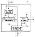
図17は、本実施の形態4におけるMPEG transport stream加工手段15の構成を示す図である。図17において、171はPES_private_data位置検出手段、172は、PES_private_data書き換え手段である。PES_header検出手段81とコマンド判定手段83は図8に示されたものと同様である。PES_private_dataは、図9におけるPES_extensionに含まれており、下記のPES_extension_fieldと共に、ISO/IEC13818−1に記載されている。
【0065】
PES_private_data位置検出手段171は、入力されるPES_header認識信号85と読み出されたMPEG transport stream 1eを解析し、MPEG transport stream 1eの中にPES_private_dataとPES_extension_fieldがある場合は、PES_extension_fieldの位置と書き込まれているデータの長さを検出し、PES_private_data認識信号173としてPES_private_data書き換え手段172に送信する。
【0066】
PES_private_data位置検出手段171は、入力されるPES_header認識信号85と読み出されたMPEG transport stream 1eを解析し、MPEG transport stream 1eの中にPES_private_dataが存在し、PES_extension_fieldが存在しない場合は、PES_extension_fieldの書き込み位置を検出し、PES_private_data認識信号173としてPES_private_data書き換え手段172に送信する。
【0067】
PES_private_data位置検出手段171は、入力されるPES_header認識信号85と読み出されたMPEG transport stream 1eとを解析し、MPEG transport stream 1eの中にPES_private_dataがない場合は、PES_private_dataを書き込む位置を検出し、PES_private_data認識信号173としてPES_private_data書き換え手段172に送信する。
【0068】
PES_private_data認識信号173において、PES_private_dataとPES_extension_fieldとがあると示された場合、PES_private_data書き換え手段172は、読み出されたMPEG transport stream 1eの、PES_extension_field_lengthの長さに、各ピクチャ毎の制御信号を記述するのに必要な長さを加算し、PES_extension_fieldに各ピクチャ毎の制御信号を加える。さらにPES_packet_length、PES_header_lengthも図8と同様に書き換える。各ピクチャ毎の制御信号の記述例を図18に示す。
【0069】
図18において、PESに含まれているピクチャの枚数をn枚とする。先頭に、逆再生時のピクチャ制御信号を記述していることを示す記述を1byte設置し、その後ろに、そのPESに含まれる各ピクチャの制御信号を1byteずつ記述する。各ピクチャの制御信号は、図10または図17で示された制御信号を使用してもよい。こうすることで、PESに含まれる全てのピクチャの制御信号をn+1byteの長さで記述することができる。またこの記述を行った場合、図1の再生制御手段1cも、この制御信号を認識できるようにする。
【0070】
PES_private_data認識信号173において、PES_private_dataが存在し、PES_extension_fieldが存在しないと示された場合、PES_private_data書き換え手段172は、読み出されたMPEG transport stream 1eの、PES_extension_flag のビットに1を立て、PES_extension_field_lengthの長さに、各ピクチャ毎の制御信号を記述するのに必要な長さを加算し、PES_extension_fieldに各ピクチャ毎の制御信号を加える。さらにPES_packet_length、PES_header_lengthも図8と同様に書き換える。
【0071】
PES_private_data認識信号173において、PES_private_dataが存在しないと示された場合、PES_private_data書き換え手段172は、読み出されたMPEG transport stream 1eの、PES_extension_flagに1を立てPES_private_dataの位置に、各ピクチャの制御信号をPES_private_dataとして書き加える。さらにPES_packet_length、PES_header_lengthも図8と同様に書き換える。
【0072】
以上の構成により、1個のPESに複数のピクチャが含まれている場合でも、各ピクチャ毎の制御信号を記述することができる。これは、1個のPESに1枚のピクチャが含まれていても有効である。
このように本実施の形態4によれば、ピクチャ単位の制御信号を、PES_headerのPES_private_data領域に書き込むようにしたので、PESに複数(n個)のピクチャが含まれる場合においても、全てのピクチャの制御信号をn+1バイトの長さで記述することができ、PESに複数のピクチャが含まれる場合においても対応することができる。
【0073】
(実施の形態5)
次に本発明の実施の形態5にかかる再生画像伝送装置について説明する。図13におけるMPEGデコード装置31は、入力するMPEG transport stream 1gまたは、MPEG transport stream 1gから取り出した、Video elementary streamを蓄積するためのバッファを持っている。図19にそのバッファに蓄積される画像データの時系列変化を示す。
【0074】
図19において、縦軸は蓄積データ量を示し、横軸は時間を示す。191の線は蓄積データ量の変化を示している。MPEG transport stream 1gが入力されると、192の部分で示されるように、バッファに蓄積されるデータ量が増加し、画像がデコードされるに従い、193の部分のようにバッファに蓄積されるデータ量が減少する。しかしながら、画像のデコードやその表示において、バッファには、初期状態を除き、一定量のデータが蓄積されていないと、MPEGデコード装置31で希望するようなデコードや表示が行われなかったり、再生装置16が誤った動作をしたりする可能性がある。194の線で示した線は、MPEGデコード装置31を含む再生装置16が正常な再生を行う為に必要とされるバッファ蓄積量の下限を示している。
【0075】
図19において、195は、194の線で示した下限を下回っている状態であり、196は、バッファが空になった状態である。こういう状態をアンダーフロー状態とした場合、アンダーフロー状態では、再生装置16が正常な動作を行わなくなる場合がある。アンダーフローは、通常のMPEG画像では発生しないが、逆再生等の特殊再生により、連続しない画像をつなぎ合わせると、つなぎ合わせたピクチャとピクチャの切れ目等で発生することが多い。
【0076】
図20は、このような問題を防ぐために、実施の形態1で示した送信装置11の構成に、符号量監視手段201、ダミーデータ生成手段202、セレクタ203を、送信装置に付与したものである。
すなわち、図20において、11aは送信装置であり、符号量監視手段201は読み出されたMPEG transport stream 1eの符号量を監視し、アンダーフロー状態になりうるかどうかを監視する。そして、読み出されたMPEG transport stream 1eにおいてアンダーフローが発生しうると符号量監視手段201が判断すると、アンダーフロー発生信号204をダミーデータ生成手段202に送信する。
【0077】
ダミーデータ生成手段202は、アンダーフロー状態を発生させないようにダミーパケット205を生成して、セレクタ203に送信する。ダミーデータ生成手段202は、ダミーパケット205として、MPEG transport streamのバッファのアンダーフローに対応する場合はNULLパケットのMPEG transport streamパケットを生成し、MPEG video elementary streamのピクチャ間のアンダーフローに対応するときは、MPEG video elementary streamのstuffing dataをペイロードに持つMPEG transport streamを生成する。
【0078】
セレクタ203は、ダミーパケット205を、加工されたMPEG transport stream 1fに挿入して、MPEG transport stream206として、IEEE1394送受信手段13に送付する。
【0079】
ここで、図21にセレクタ203の動作を示す。アンダーフローは、読み出されたMPEG transport stream 1eのパケット間隔を、ダミーパケット205で埋めることで解決することができる。セレクタ203は読み出されたMPEG transport stream 1eのパケットの送出間隔を埋めるようにして、ダミーパケット205を挿入し、MPEG transport stream206を送出する。
【0080】
以上のように本実施の形態によれば、符号量監視手段201によって送信装置11aに蓄積装置12から読み出されるMPEG transport stream 1eの符号量を監視し、アンダーフロー状態が検出されると、ダミーデータ生成手段202からアンダーフロー状態を発生させないようにダミーパケット205を生成してこれをMPEG transport streamの間に埋め込むように構成したので、再生装置16におけるアンダーフローを防ぐことが可能になり、デコード処理が破綻して画面がフリーズするなどの不具合を防止することができる。
【0081】
(実施の形態6)
次に本発明の実施の形態6にかかる再生画像伝送装置について説明する。図22は本実施の形態6における再生画像伝送装置のMPEGトランスポートストリーム加工手段を示すブロック図であり、その他の部分については図1と同様である。図において、15aはMPEGトランスポートストリーム加工手段を示し、本実施の形態6では図17に示したMPEGトランスポートストリーム加工手段15において、PES_Header検出手段81、PES_private_data位置検出手段171、PES_private_data書き換え手段172に替えて、それぞれPicture_header検出手段211、Temporal_Reference検出手段223、Temporal_Reference書き換え手段225が設けられている。本実施の形態6では、ISO/IEC13818−2で規定されるピクチャヘッダに含まれるTemporal_Referenceの領域にピクチャの制御信号を書き込むようにしものである。
【0082】
次に動作について説明する。
読み出されたMPEGトランスポートストリーム1eが入力されると、Picture_Header検出手段221は、MPEGトランスポートストリーム1eに含まれるピクチャヘッダを検出し、ピクチャヘッダ検出信号222を送出する。Temporal_Reference検出手段223では、ピクチャヘッダ検出信号222を検出すると、ピクチャヘッダに含まれるTemporal_Referenceの位置を検出してTemporal_Referenceの位置を示す検出信号224を送出する。Temporal_Reference書き換え手段225では、上記Temporal_Referenceの位置を示す検出信号224で示されたでTemporal_Reference位置にピクチャ単位の制御信号を書き込む。
【0083】
例えば、デコードを実行、かつデコードした画像を表示する場合には、デコード画像を表示する順番をTempora1_Referenceに書き込み、また、デコードを実行、かつデコードした画像は表示しない場合には、Temporal_Referenceに対して、10’b1111111111(1024番目)等の通常の画像では殆ど使用することのないピクチャ表示順番を与えるようにする。こうすることで、デコードを実行、かつデコードした画像は表示しない、という制御を実現することができる。また、Temporal_Referenceは全てのピクチャに存在するため、どのPESヘッダとピクチャの位置が同期していなくても各ピクチャ毎にデコード信号を送信することができる。
【0084】
このように本実施の形態6によれば、ピクチャを制御するための制御信号を、Picture_Headerに含まれるTemporal_Referenceに書き込んで表示すべき画像データとともに、IEEE1394ネットワークにおけるisochronous転送にて伝送するようにしたから、1個のPESに複数個のピクチャが含まれる場合や、ピクチャとPESのヘッダ位置とが非同期であった場合においても、正常な逆再生を行うことができる。
【0085】
【発明の効果】
以上のように、本発明の請求項1にかかる再生画像伝送装置によれば、帯域が保証されたisochronous転送と、非同期にて転送が行われるasynchronous転送の2つの転送モードを有するIEEE1394インターフェースにて構成された双方向ネットワーク間で再生画像を伝送する再生画像伝送装置であって、再生画像データを蓄積するデータ蓄積手段と、上記再生画像データと、該再生画像データの再生制御を行うための再生制御パラメータとを上記isochronous転送にて伝送するよう上記データ蓄積手段より読み出した再生画像データを、自身の再生制御を行うためのタイムスタンプ情報が加工や再生制御により破綻しないように加工するデータ加工手段とを備えたものとしたので、ピクチャ単位の制御信号と、転送する再生画像データの同期を完全に保証することが可能になり、ピクチャ単位でのデコード制御により逆再生画像の再生が可能になるという効果が得られる。
【0086】
また、本発明の請求項2にかかる再生画像伝送装置によれば、請求項1記載の再生画像伝送装置において、上記再生画像データがMPEGトランスポートストリームであり、上記再生制御パラメータは、上記MPEGトランスポートストリームのデコード及び表示処理の指示に関するものとしたので、ピクチャ単位でのデコード制御によりMPEGトランスポートストリームの逆再生画像の再生が可能になるという効果が得られる。
【0087】
また、本発明の請求項3にかかる再生画像伝送装置によれば、請求項2記載の再生画像伝送装置において、上記データ加工手段は、デコードと表示を行う、デコードは行うが表示は行わない、デコードは行わず表示は前回の画像をそのまま保持する、デコードは行わず、画像の表示も行わないという再生制御パラメータをISO/IEC13818−1にて規定されるPES_header中のDSMのtrick_mode_controlのフラグの3’b101から3’b111までの領域とその下位5ビットに割り当てるものとしたので、再生装置側における再生画像のデコード,再生,表示制御にかかわる再生制御パラメータをMPEGの規定されるフォーマットを利用して伝送することができるという効果が得られる。
【0088】
また、本発明の請求項4にかかる再生画像伝送装置によれば、請求項3記載の再生画像伝送装置において、上記データ加工手段は、デコードと表示を行うという再生制御パラメータに、ISO/IEC13818−1にて規定されるPES_header中のDSMのtrick_mode_control=3’b100と、rep_cntrl≠5’b00000を割り当て、デコードは行うが表示は行わないをPES_header中のDSMのtrick_mode_control=3’b100と、rep_cntrl=5’b00000を割り当てるものとしたので、再生装置側における再生画像のデコード,再生,表示制御にかかわる再生制御パラメータをMPEGの規定されるフォーマットを利用して伝送することができるという効果が得られる。
【0089】
また、本発明の請求項5にかかる再生画像伝送装置によれば、請求項2記載の再生画像伝送装置において、上記データ加工手段は、デコードと表示を行う、デコードは行うが表示は行わない、デコードは行わず表示は前回の画像をそのまま保持する、デコードは行わず、画像の表示も行わないという制御信号をISO/IEC13818−1にて規定されるPES_header中のPES_private_data、又はPES_extension_field_lengthに記述するものとしたので、再生装置側における再生画像のデコード,再生,表示制御にかかわる再生制御パラメータをMPEGの規定されるフォーマットを利用して伝送することができるとともに、1個のPESの中に複数個のピクチャが含まれる場合においても各ピクチャの制御を行うことができるという効果が得られる。
【0090】
また、本発明の請求項6にかかる再生画像伝送装置によれば、請求項2記載の再生画像伝送装置において、上記データ蓄積手段から読み出された再生画像データの読み出し符号量を監視し、該符号量が所定値以下になると、再生装置におけるデコーダのバッファに蓄積されたデータが復号化処理に必要量以下となったことを示すアンダーフロー発生信号を発生する符号量監視手段と、上記符号量監視手段から発生されたアンダーフロー発生信号を受けて、ダミーパケットを発生するダミーデータ生成手段と、上記データ加工手段で加工されたMPEG transport streamの間に上記ダミーパケットを埋め込むセレクタ手段とを備えたものとしたので、再生装置側におけるバッファアンダーフローを防ぐことが可能になり、デコード処理が破綻して画面がフリーズするなどの不具合を防止することができるという効果が得られる。
【0091】
また、本発明の請求項7にかかる再生画像伝送装置によれば、帯域が保証されたisochronous転送と、非同期にて転送が行われるasynchronous転送の2つの転送モードを有するIEEE1394インターフェースにて構成された双方向ネットワーク間で再生画像を伝送する再生画像伝送装置であって、上記再生画像データ、及び該再生画像データを逆再生する際に必要な再生制御パラメータとを蓄積するデータ蓄積手段と、上記再生画像データと、上記再生制御パラメータとを上記isochronous転送にて伝送するものとしたので、受信装置側より逆再生のコマンドが送信されると、逆再生画像を蓄積するデータ蓄積手段から読み出された所定の画像データをIEEE1394ネットワークを介して受信装置側に伝送するだけで、受信装置側において逆再生画像を容易に再生することができるという効果が得られる。
【0092】
また、本発明の請求項8にかかる再生画像伝送装置によれば、請求項2記載の再生画像伝送装置において、上記データ加工手段は、デコードと表示を行う、デコードは行うが表示は行わない、デコードは行わず表示は前回の画像をそのまま保持する、デコードは行わず、画像の表示も行わないという再生制御パラメータをISO/IEC13818−2にて規定されるPicture_Header中のTemporal_Referenceに記述するものとしたので、1個のPESに複数個のピクチャが含まれる場合や、ピクチャとPESのヘッダ位置とが非同期であった場合においても、正常な逆再生を行うことができるという効果が得られる。
【図面の簡単な説明】
【図1】本発明の実施の形態1にかかる再生画像伝送装置の構成を示すブロック図である。
【図2】従来の画像再生装置の構成を示すブロック図である。
【図3】従来のMPEGデコード装置の構成を示す図である。
【図4】P、Bピクチャを使った順方向再生の方法を説明するための図である。
【図5】P、Bピクチャを使った逆方向再生の方法の方法を説明するための図である。
【図6】IEEE1394送受信手段の構成を示す図である。
【図7】MPEGトランスポートストリームの構成を説明するための図である。
【図8】MPEGトランスポートストリーム加工手段の構成を示すブロック図である。
【図9】MPEGで規定されるPESの構成を説明するための図である。
【図10】trick_mode_controlとDSM_dataの書き換え内容を説明するための図である。
【図11】再生装置を構成する制御手段の構成例を示す図である。
【図12】ピクチャ制御信号の生成タイミングを説明するための図である。
【図13】上記実施の形態1にかかる再生画像伝送装置から伝送されたMPEGトランスポートストリームを受信する受信機を構成するMPEG画像再生手段の構成を示す図である。
【図14】本発明の実施の形態2にかかる再生画像伝送装置の構成を示すブロック図である。
【図15】上記実施の形態2における再生画像伝送装置の逆再生画像蓄積手段に蓄積される逆再生画像の生成方法を説明するための図である。
【図16】本発明の実施の形態3にかかる再生画像伝送装置を構成するMPEGトランスポートストリーム加工手段によるコマンド設定の一例を示す図である。
【図17】本発明の実施の形態4にかかる再生画像伝送装置におけるMPEGトランスポートストリーム加工手段の構成を示す図である。
【図18】上記実施の形態4にかかる再生画像伝送装置における、各ピクチャ毎の制御信号の記述例を示す図である。
【図19】バッファに蓄積される画像データの蓄積量変化を説明するための図である。
【図20】本発明の実施の形態5にかかる再生画像伝送装置の構成を示すブロック図である。
【図21】上記実施の形態5にかかる画像伝送装置を構成するセレクタの動作を説明するための図である。
【図22】本発明の実施の形態6にかかる再生画像伝送装置のMPEGトランスポートストリーム加工手段の構成を示すブロック図である。
【符号の説明】
11 送信装置
12 蓄積装置(ハードディスク)
13 IEEE1394送受信手段
14 読み出し手段
15 MPEG transport stream加工手段
16 再生装置
17 IEEE1394送受信手段
18 コマンド生成手段
19 MPEG画像再生手段
1a 再生コマンド
1b IEEE1394ネットワーク
1c 再生制御手段
1d 読み出し制御
1e 読み出されたMPEG transport stream画像
1f 加工されたMPEG transport stream画像
1g MPEG transport stream
21 送信装置
22 蓄積装置(ハードディスク)
23 IEEE1394送受信手段
24 ハードディスク制御手段
25 再生装置
26 IEEE1394送受信手段
27 コマンド生成手段
28 画像再生手段
2a 再生コマンド
2b IEEE1394ネットワーク
31 MPEGデコード装置
32 参照画像メモリ
33 フレームメモリ
34 モニタ
35 表示制御
36 スイッチ
3a MPEG画像入力
5A デコーダ31でデコードを行うが、画像表示は行うというコマンド
5B デコーダ31でデコードを行い、画像表示も行わないというコマンド
61 asynchronous転送手段
62 isochronous転送手段
63 IEEE1394リンク層
64 IEEE1394物理層
71 エレメンタリストリーム
81 PES_header検出手段
82 DSM位置検出手段
83 コマンド判定手段
84 DSM書き換え手段
85 PES_header認識信号
86 DSM認識信号
87 逆再生信号
111 コマンド抽出手段
112 Picture_header検出手段
113 同期出力手段
114 ピクチャ制御信号
115 ピクチャ同期信号
131 コマンド受信
132 表示制御
133 デコード制御
141 逆再生画像蓄積装置
142 逆再生画像蓄積装置読み出し手段
151 IEEE送受信手段
152 蓄積媒体
153 コマンド生成手段
171 PES_private_data位置検出手段
172 PES_private_data書き換え手段
173 PES_private_data認識信号
191 蓄積データ量の変化線
192 蓄積データの増加
193 蓄積データの減少
194 再生装置16で規定される最低符号量
195 バッファが空になる状態
201 符号量監視手段
202 ダミーデータ生成手段
203 セレクタ
204 アンダーフロー発生信号
205 ダミーパケット
206 MPEG transport stream[0001]
BACKGROUND OF THE INVENTION
The present invention relates to an image reproduction system for transmitting MPEG images stored in a hard disk of a transmitter to a receiving device via a bidirectional network such as IEEE 1394, and in particular, a reverse using P or B picture in the receiving device. The present invention relates to one that generates a reproduction image.
[0002]
[Prior art]
In recent years, with the increase in the speed of networks and the increase in capacity of hard disks, a system has emerged in which digital images recorded in MPEG or the like are stored in a hard disk and transmitted to a receiver via the network. In this video network system, an IEEE 1394 high-speed network is used, and a storage device having a hard disk and a playback device for receiving and playing back video are connected using the network.
[0003]
IEEE 1394 has an isochronous transfer function that guarantees the amount of data transferred within a certain time. Since isochronous transfer guarantees the amount of data to be transferred in a certain period, it is suitable for video and audio transmissions that require real-time performance, and is installed in many BS digital broadcasting STBs and digital VCR devices. .
[0004]
The IEEE 1394 has an asynchronous transfer for transferring data and commands. This asynchronous transfer is an asynchronous transfer in which the right to use the bus is acquired and transmitted when it is desired to send data, and the amount of data transferred during a certain period is not guaranteed.
[0005]
At present, IEEE 1394 is the DVB (European Digital Broadcasting) and IEEE 1394T. A. Detailed commands are negotiated by (trade association). In particular, IEEE 1394T. A. , A method for transmitting an MPEG transport stream on IEEE 1394, a command for controlling a digital VCR using a hard disk, and the like have been formulated. These commands are transferred using asynchronous transfer.
[0006]
However, in IEEE 1394, even if packets are sent in the order of asynchronous transfer and isochronous transfer, there is no guarantee that packets will be transmitted in the order of asynchronous transfer and isochronous transfer on the network. That is, even if packets are sent to the IEEE 1394 packet transmission device in the order of asynchronous transfer and isochronous transfer, the packets may be sent in the order of isochronous transfer and asynchronous transfer on the IEEE 1394 network.
On the other hand, when a reverse reproduction image using a B picture (bidirectional predictive encoded image) or a P picture (interframe forward predictive encoded image) is generated as an MPEG image, the display of the decoded image is changed for each picture. Must.
[0007]
FIG. 3 shows the configuration of an MPEG decoding apparatus using B pictures and P pictures. The MPEG image input 3a to be decoded is input to the
[0008]
Here, a reverse reproduction method using P and B pictures will be described. FIG. 4 shows a forward reproduction method using P and B pictures. During forward playback, B0, I1, B2, P3, B4,I5,B6, P7 to display MPEG decodingDevice31, I1, B0, P3, B2,I5,BImages are input in the order of 4, P7, and B6. Then MPEG decodingDevice31 is a referenceimageA reference image necessary for decoding the B picture is stored in the
[0009]
MPEG decoding deviceThe images decoded at 31 are stored in the
[0010]
FIG. 5 shows a backward reproduction method using P and B pictures. A method of reversely reproducing the image shown in FIG. 4 in the order of B4, P3, B2, and I1 will be described. To decode the B4 image, reference images P3 and I5 are required. However, in order to create a reference image of P3, a further forward picture of I1 is necessary. That is, in order to generate the B4 picture, four pictures I1, P3, I5, and B4 are required. Similarly, I1 and P3 pictures are required for decoding the P3 image, and I1, P3, and B2 pictures are required for decoding the B2 picture. The I1 picture does not require other pictures to decode.
[0011]
Here, when decoding the picture of B4, in addition to the picture of B4, I1, P3,I5 pictures must be decoded. Therefore, the decoded I1, P3ISee picture 5imageAlthough stored in the
As described above, during the reverse reproduction of the MPEG image, the reverse reproduction image using the P and B pictures is generated by adding a function to perform the control of performing the decoding but not displaying for each picture. Is possible.
[0012]
FIG. 2 shows a conventional image transmission apparatus. In the figure,
[0013]
25 isPlayback device26 is an IEEE 1394 transmission / reception means, 27 is a command generation means, and 28 is an image reproduction means. In the figure,Accumulator22 includes an MPEG transport stream6aMPEG images are recorded in the form of The command generation means 27 of the
[0014]
The IEEE 1394 transmission / reception means 26 is a reproduction command.2aIs converted into an asynchronous packet on IEEE1394, transmitted through the
[0015]
The IEEE1394 transmission / reception means 23 isStorage device 22MPEG transport stream read from6aIs converted into an isochronous packet and sent to the IEEE 1394
[0016]
FIG. 6 shows the configuration of the IEEE1394 transmission / reception means 23 and 26. The
[0017]
FIG. 7 shows the structure of the MPEG transport stream. In FIG. 7,
[0018]
Then, after dividing the PES stream into an arbitrary size, a header defined by ISO / IEC13818-1 is added to form a fixed packet of 188 bytes long, and various information is added to make a multi-channel MPEG. It is a transport stream.
Here, the MPEG image refers to an MPEG transport stream defined by ISO / IEC13818-1 in which an elementary stream is a signal defined by ISO / IEC13818-2 or ISO / IEC11172-2. To do.
[0019]
In the conventional configuration shown in FIG. 2, when the image stored in the hard disk is played back in the forward direction, stopped, and reversely played back only with the I picture, the
[0020]
On the other hand, when reverse playback using P and B pictures is performed, a decoding control signal must be generated for each picture. Since this decoding control signal depends on the configuration of GOP (Group Of Picture), it is included in the hard disk control means 24 of FIG. Therefore, the display control in the hard disk control means 24PartThe decode control signal generated by 35 must be transmitted to the
That is, MPEG pictures transferred by isochronous transfer and display controlPartIn synchronization with the asynchronous transfer of the decode control signal generated by 35, it must be transferred over the IEEE 1394
[0021]
For this purpose, the IEEE 1394 transmission / reception means 23 controls the display control.PartWhen an MPEG packet transferred by isochronous transfer is sent to the isochronous transfer means 62 after the asynchronous packet of the decoding control signal generated by 35 is input to the asynchronous transfer means 61, the IEEE 1394Link layerNo. 63 may not perform the first asynchronous transfer input first, but may perform the first isochronous transfer input later. This is because the transmission order of asynchronous transfer and isochronous transfer is not guaranteed in the IEEE 1394 standard.
[0022]
Even if transmission is performed in the order of asynchronous transfer and isochronous transfer, the transmission order may be reversed after reception. In order to guarantee the transmission order of asynchronous transfer and isochronous transfer, after confirming the completion of asynchronous transfer, that is, during this time, isochronous transfer is stopped and asynchronous transfer is performed. In the case of transmission, since the transmission bandwidth of asynchronous transfer is not guaranteed, the transfer speed is limited to asynchronous transfer, and the bandwidth of isochronous transfer may not be guaranteed. The commands such as playback and stop do not need to consider the transmission band before and after the command, but regarding the control signal for each picture, the transmission band before and after the command must be guaranteed.
That is, in the conventional configuration, there is a problem that a decoding control signal synchronized with a picture cannot be transmitted and received in order to perform reverse reproduction of the MPEG image.
[0023]
[Problems to be solved by the invention]
The conventional reverse reproduction image generation apparatus is configured as described above, and when an apparatus for generating a reverse reproduction image and an apparatus for decoding the reverse reproduction image are connected via an IEEE 1394 network, asynchronous transfer and isochronous are performed. Since the transfer order with respect to transfer is not guaranteed on IEEE1394, the MPEG picture transferred by isochronous transfer and the control signal transferred by asynchronous transfer cannot be synchronized, and the reversely reproduced image cannot be decoded. was there.
[0024]
The present invention has been made in view of such a problem, and guarantees the synchronization of an MPEG picture received on the playback apparatus side and its control signal, and enables playback of MPEG reverse playback using P and B pictures. An object is to provide a transmission apparatus.
[0025]
[Means for Solving the Problems]
The reproduction image transmission apparatus according to
[0026]
A reproduction image transmission apparatus according to claim 2 of the present invention is the reproduction image transmission apparatus according to
[0027]
A reproduction image transmission apparatus according to
[0028]
According to a fourth aspect of the present invention, there is provided the reproduced image transmission apparatus according to the third aspect, wherein the data processing means is set to ISO / IEC13818-1 with a reproduction control parameter for decoding and display. DSM's trick_mode_control = 3′b100 and rep_cntl ≠ 5′b00000 are assigned in the PES_header specified in the above, and decoding is performed but no display is performed. Is assigned.
[0029]
A reproduction image transmission apparatus according to
[0030]
A reproduction image transmission apparatus according to a sixth aspect of the present invention is the reproduction image transmission apparatus according to the second aspect, wherein the read code amount of the reproduction image data read from the data storage means is monitored, and the code amount Code amount monitoring means for generating an underflow generation signal indicating that the data stored in the decoder buffer in the reproducing apparatus is less than the required amount for decoding processing when A dummy data generating means for generating a dummy packet in response to an underflow generation signal generated from the signal, and a selector means for embedding the dummy packet between the MPEG transport stream processed by the data processing means. is there.
[0031]
According to a seventh aspect of the present invention, there is provided a reproduction image transmission apparatus having a bidirectional configuration including an IEEE 1394 interface having two transfer modes: an isochronous transfer in which a bandwidth is guaranteed and an asynchronous transfer in which an asynchronous transfer is performed. A reproduction image transmission apparatus for transmitting a reproduction image between networks, the data storage means for storing the reproduction image data and reproduction control parameters necessary for reverse reproduction of the reproduction image data, and the reproduction image data And the reproduction control parameter are transmitted by the isochronous transfer.
[0032]
The reproduction image transmission apparatus according to
[0033]
DETAILED DESCRIPTION OF THE INVENTION
(Embodiment 1)
FIG. 1 is related to
[0034]
[0035]
The
[0036]
The operation will be described below with reference to FIG. As in the conventional example, in the same figure as in FIG. A. A
[0037]
Since the configuration of the IEEE1394 transmission / reception means 13 and 17 is the same as that shown in FIG. 6, the details thereof are omitted here.
The IEEE 1394 transmission / reception means 13 extracts the
[0038]
The
[0039]
Here, if the
Therefore, the MPEG transport stream processing means 15 gives a signal for controlling the reproduction control means 1c to the MPEG transport stream. The processed
[0040]
FIG. 8 shows the configuration of the MPEG transport stream processing means 15, which is composed of a PES (Packetized Elementary Stream) _header detection means 81, a DSM (Digital Storage Media) position detection means 82, a command determination means 83, and a DSM rewrite means 84. ing.
[0041]
The read
[0042]
FIG. 9 shows the configuration of the PES. The configuration of the PES in FIG. 9 is defined by ISO / IEC 13818-1. In the present embodiment, it is assumed that the MPEG image included in one PES is one picture. In FIG. 8, when the
[0043]
The
[0044]
If the DSM_trick_mode_flag is not set, the
[0045]
Next, an example of rewrite contents of trick_mode_control and DSM_data rewritten by the DSM rewrite means 84 is shown in FIG. In FIG. 10, a command A indicates a command description for decoding an MPEG image and displaying the decoded image, and is the same as the
[0046]
The MPEG transport stream processing means 15 performs display control in FIG.PartThe command generated in 35 is assigned to the PES_header. The MPEG transport stream processing means 15 performs processing so that the command indicated by 5B in FIG. 5 indicates the command B in FIG. 10 and the command indicated by 5A in FIG. 5 indicates the command A in FIG. In FIG. 1, the
[0047]
The isochronous packet transmitted to the IEEE 1394
[0048]
FIG. 11 shows a configuration example of the reproduction control unit 1c. In FIG. 11, the input
[0049]
When the Picture_header is extracted from the
[0050]
When the
The MPEG
[0051]
Command receptionPart131 receives the
[0052]
As described above, according to the present embodiment, when transmitting the MPEG transport stream data from the
[0053]
(Embodiment 2)
FIG. 14 shows an image transmission apparatus according to the second embodiment. 2 denote the same or corresponding parts, and the
[0054]
In FIG. 15,
[0055]
The operation is described belowYouThe The
[0056]
At that time, a reverse reproduction command is transmitted such that all I, P, and B images are reproduced by reverse reproduction by using a reverse reproduction command of 1 × speed. The reverse reproduction image generated by the
[0057]
When the
[0058]
In the backward reproduction, since the read backward reproduction image has already been subjected to DSM processing,21aIn this case, it is not necessary to perform reworking. For this reason, if there is a
[0059]
As described above, according to the second embodiment, since all the reversely reproduced images of I, P, and B pictures are stored in the
[0060]
(Embodiment 3)
Next, a reproduced image transmission apparatus according to the third embodiment of the present invention will be described. FIG. 16 shows a processing example of a form different from FIG. 10 shown in the first embodiment in the example of the command processed by the MPEG transport stream processing means 15 in the image transmission apparatus of the first embodiment. In FIG. 16, trick_mode_controlUnlike FIG. 10, the data of 3′b100 is shown. This indicates slow_reverse in ISO / IEC13818-1, indicating slow playback in the reverse direction. trick_mode_controlHowever, in the case of 3'b100, a parameter called rep_cntrl indicating the number of times the picture is displayed is set in the lower 5 bits. In this parameter, a value other than 0 is set for command A, and a value of 0 is set for command B. Command C and command D are not used.
[0061]
In the first embodiment, the command is assigned to an area not defined in ISO / IEC13818-1. However, in the third embodiment, only the command A and the command B are set according to the range defined in ISO / IEC13818-1. By doing so, it is possible to reduce the scale in which the
[0062]
(Embodiment 4)
Next, a reproduced image transmission apparatus according to the fourth embodiment of the present invention will be described. In the first to third embodiments, the case where the number of pictures included in one PES is one has been described as an example. However, a single PES may include a plurality of pictures. In this case, only the extension of the DSM code shown in the first to third embodiments has only a description area of 8 bits in the DSM, so only one picture can be described in one PES. It is not possible to control a plurality of pictures included in one PES.
[0063]
In the fourth embodiment, control in units of pictures is written in the PES_private_data area of the PES_header so as to cope with a case where a single PES includes a plurality of pictures.
[0064]
FIG. 17 shows MPEG transport stream processing means in the fourth embodiment.15FIG. In FIG. 17,
[0065]
The PES_private_data position detection means 171 receives the input
[0066]
The PES_private_data position detection means 171 receives the input
[0067]
The PES_private_data position detection means 171 receives the input
[0068]
When the
[0069]
In FIG. 18, the number of pictures included in the PES is n. A description indicating that a picture control signal at the time of reverse reproduction is described is set at the beginning, and after that, a control signal for each picture included in the PES is described by 1 byte. The control signal shown in FIG. 10 or FIG. 17 may be used as the control signal for each picture. By doing so, the control signals of all the pictures included in the PES can be described with a length of n + 1 bytes. When this description is made, the reproduction control means 1c in FIG. 1 can also recognize this control signal.
[0070]
When the
[0071]
When the
[0072]
With the above configuration, even when a plurality of pictures are included in one PES, a control signal for each picture can be described. This is effective even if one picture is included in one PES.
As described above, according to the fourth embodiment, since the control signal for each picture is written in the PES_private_data area of the PES_header, even when a plurality of (n) pictures are included in the PES, The control signal can be described with a length of n + 1 bytes, and it is possible to cope with a case where a plurality of pictures are included in the PES.
[0073]
(Embodiment 5)
Next, a reproduced image transmission apparatus according to the fifth embodiment of the present invention will be described. The
[0074]
In FIG. 19, the vertical axis indicates the amount of accumulated data, and the horizontal axis indicates time. A
[0075]
In FIG. 19, 195 is a state that is below the lower limit indicated by the
[0076]
In FIG. 20, in order to prevent such a problem, the code
That is, in FIG. 20,
[0077]
The dummy
[0078]
The
[0079]
Here, FIG. 21 shows the operation of the
[0080]
As described above, according to the present embodiment, the MPEG transport stream read from the
[0081]
(Embodiment 6)
Next, a reproduced image transmission apparatus according to the sixth embodiment of the present invention will be described. FIG. 22 is a block diagram showing the MPEG transport stream processing means of the playback image transmission apparatus in the sixth embodiment, and the other parts are the same as those in FIG. In the figure,
[0082]
Next, the operation will be described.
When the read
[0083]
For example, when decoding and displaying a decoded image, the order in which the decoded images are displayed is written in Tempora1_Reference, and when decoding is performed and the decoded image is not displayed, Temporal_Reference is 10'b1111111111 (No. 1024Eye) And the like are given a picture display order that is rarely used. By doing so, it is possible to realize control of executing decoding and not displaying the decoded image. In addition, since Temporal_Reference exists in all pictures, a decoded signal can be transmitted for each picture regardless of which PES header and picture position are not synchronized.
[0084]
As described above, according to the sixth embodiment, the control signal for controlling the picture is transmitted by the isochronous transfer in the IEEE 1394 network together with the image data to be written and displayed in the Temporal_Reference included in the Picture_Header. Even when a plurality of pictures are included in one PES, or when the picture and the header position of the PES are asynchronous, normal reverse reproduction can be performed.
[0085]
【The invention's effect】
As described above, according to the reproduction image transmission apparatus according to
[0086]
According to a reproduction image transmission apparatus of claim 2 of the present invention, in the reproduction image transmission apparatus according to
[0087]
Further, according to the reproduction image transmission apparatus according to
[0088]
According to the reproduction image transmission apparatus of claim 4 of the present invention, in the reproduction image transmission apparatus according to
[0089]
According to the reproduction image transmission apparatus of
[0090]
According to the reproduction image transmission apparatus of claim 6 of the present invention, in the reproduction image transmission apparatus according to claim 2, the read code amount of the reproduction image data read from the data storage means is monitored, Code amount monitoring means for generating an underflow generation signal indicating that the data stored in the decoder buffer in the reproducing apparatus is less than a necessary amount for decoding processing when the code amount becomes a predetermined value or less, and the code amount In response to an underflow generation signal generated from the monitoring means, a dummy data generating means for generating a dummy packet and a selector means for embedding the dummy packet between the MPEG transport stream processed by the data processing means are provided. As a result, it is possible to prevent buffer underflow on the playback device side. It is possible to prevent such a problem that the screen processing is broken and the screen freezes.
[0091]
The reproduction image transmission apparatus according to claim 7 of the present invention is configured with an IEEE 1394 interface having two transfer modes: isochronous transfer with guaranteed bandwidth and asynchronous transmission with asynchronous transfer. A reproduction image transmission apparatus for transmitting a reproduction image between two-way networks, the data storage means for storing the reproduction image data and a reproduction control parameter required for reverse reproduction of the reproduction image data, and the reproduction Since the image data and the playback control parameter are transmitted by the isochronous transfer, when a reverse playback command is transmitted from the receiving device side, it is read from the data storage means for storing the reverse playback image. Device for receiving predetermined image data via IEEE 1394 network Just transmission, the effect is obtained that the reverse playback image can be easily reproduced in the receiving apparatus.
[0092]
According to the reproduced image transmission apparatus of
[Brief description of the drawings]
FIG. 1 is a block diagram showing a configuration of a reproduced image transmission apparatus according to a first embodiment of the present invention.
FIG. 2 is a block diagram showing a configuration of a conventional image reproduction apparatus.
FIG. 3 is a diagram showing a configuration of a conventional MPEG decoding apparatus.
FIG. 4 is a diagram for explaining a method of forward reproduction using P and B pictures.
FIG. 5 is a diagram for explaining a method of backward reproduction using P and B pictures.
FIG. 6 is a diagram illustrating a configuration of an IEEE 1394 transmission / reception unit.
FIG. 7 is a diagram for explaining a configuration of an MPEG transport stream.
FIG. 8 is a block diagram showing a configuration of MPEG transport stream processing means.
FIG. 9 is a diagram for explaining a configuration of a PES defined by MPEG.
FIG. 10 is a diagram for explaining rewrite contents of trick_mode_control and DSM_data;
FIG. 11 is a diagram illustrating a configuration example of a control unit that configures the playback device.
FIG. 12 is a diagram for explaining the generation timing of a picture control signal.
FIG. 13 is a diagram showing a configuration of MPEG image playback means constituting a receiver that receives an MPEG transport stream transmitted from the playback image transmission apparatus according to the first embodiment;
FIG. 14 is a block diagram showing a configuration of a reproduced image transmission apparatus according to a second embodiment of the present invention.
FIG. 15 is a diagram for explaining a method of generating a reverse reproduction image stored in reverse reproduction image storage means of the reproduction image transmission apparatus according to the second embodiment.
FIG. 16 is a diagram illustrating an example of command setting by an MPEG transport stream processing unit included in the reproduced image transmission apparatus according to the third embodiment of the present invention;
FIG. 17 is a diagram showing a configuration of MPEG transport stream processing means in the reproduced image transmission apparatus according to the fourth embodiment of the present invention;
FIG. 18 is a diagram illustrating a description example of a control signal for each picture in the reproduced image transmission apparatus according to the fourth embodiment.
FIG. 19 is a diagram for explaining a change in the amount of image data stored in a buffer.
FIG. 20 is a block diagram showing a configuration of a playback image transmission apparatus according to a fifth embodiment of the present invention.
FIG. 21 is a diagram for explaining the operation of the selector that constitutes the image transmission apparatus according to the fifth embodiment;
FIG. 22 is a block diagram showing a configuration of MPEG transport stream processing means of the reproduced image transmission apparatus according to the sixth embodiment of the present invention.
[Explanation of symbols]
11 Transmitter
12 Storage device (hard disk)
13 IEEE1394 transmission / reception means
14 Reading means
15 MPEG transport stream processing means
16 Playback device
17 IEEE1394 transmission / reception means
18 Command generation means
19 MPEG image playback means
1a Playback command
1b IEEE 1394 network
1c Reproduction control means
1d Read control
1e MPEG transport stream image read out
1f Modified MPEG transport stream image
1g MPEG transport stream
21 Transmitter
22 Storage device (hard disk)
23 IEEE 1394 transmission / reception means
24 Hard disk control means
25 Playback device
26 IEEE 1394 transmission / reception means
27 Command generation means
28 Image reproduction means
2a Playback command
2b IEEE 1394 network
31 MPEG decoding device
32 Reference image memory
33 frame memory
34 Monitor
35 Display control
36 switches
3a MPEG image input
5A A command to decode by the
5B Command to decode by
61 Asynchronous transfer means
62 Isochronous transfer means
63 IEEE 1394 link layer
64 IEEE 1394 physical layer
71 Elementary Stream
81 PES_header detection means
82 DSM position detection means
83 Command determination means
84 DSM rewriting means
85 PES_header recognition signal
86 DSM recognition signal
87 Reverse playback signal
111 Command extraction means
112 Picture_header detection means
113 Synchronous output means
114 Picture control signal
115 picture synchronization signal
131 Command received
132 Display control
133 Decode control
141 Reverse Playback Image Storage Device
142 Reverse reproduction image storage device reading means
151 IEEE transmission / reception means
152 Storage medium
153 Command generation means
171 PES_private_data position detection means
172 PES_private_data rewriting means
173 PES_private_data recognition signal
191 Change line of accumulated data
192 Increase in accumulated data
193 Reduction of accumulated data
194 Minimum code amount specified by the
195 Buffer is empty
201 Code amount monitoring means
202 Dummy data generation means
203 selector
204 Underflow generation signal
205 dummy packet
206 MPEG transport stream
Claims (8)
再生画像データを蓄積するデータ蓄積手段と、
上記再生画像データと、該再生画像データの再生制御を行うための再生制御パラメータとを上記isochonous転送にて伝送するよう上記データ蓄積手段より読み出した再生画像データを、自身の再生制御を行うためのタイムスタンプ情報が加工や再生制御により破綻しないように加工するデータ加工手段とを備えたことを特徴とする再生画像伝送装置。A reproduction image transmission apparatus for transmitting a reproduction image between two-way networks configured with an IEEE 1394 interface having two transfer modes of isochronous transfer in which bandwidth is guaranteed and asynchronous transfer in which asynchronous transfer is performed,
Data storage means for storing reproduced image data;
The reproduction image data read from the data storage means so as to transmit the reproduction image data and the reproduction control parameter for performing reproduction control of the reproduction image data by the isochonous transfer , for performing the reproduction control of itself. A reproduction image transmission apparatus comprising data processing means for processing time stamp information so as not to fail due to processing or reproduction control .
上記再生画像データがMPEGトランスポートストリームであり、
上記再生制御パラメータは、上記MPEGトランスポートストリームのデコード及び表示処理の指示に関するものであることを特徴とする再生画像伝送装置。The playback image transmission apparatus according to claim 1, wherein
The reproduced image data is an MPEG transport stream,
The reproduction image transmission apparatus, wherein the reproduction control parameter relates to an instruction of decoding and display processing of the MPEG transport stream.
上記データ加工手段は、
デコードと表示を行う、デコードは行うが表示は行わない、デコードは行わず表示は前回の画像をそのまま保持する、デコードは行わず、画像の表示も行わないという再生制御パラメータをISO/IEC13818−1にて規定されるPES_header中のDSMのtrick_mode_controlのフラグの3’b101から3’b111までの領域とそれに続く5ビットに割り当てることを特徴とする再生画像伝送装置。The reproduction image transmission apparatus according to claim 2, wherein
The data processing means is
The playback control parameters are ISO / IEC13818-1 for decoding and displaying, performing decoding but not displaying, not performing decoding, retaining the previous image as it is, not performing decoding and displaying no image. A reproduction image transmission apparatus characterized by allocating to a region from 3'b101 to 3'b111 of a trick_mode_control flag of a DSM in a PES_header defined in the above, and subsequent 5 bits.
上記データ加工手段は、
デコードと表示を行うという再生制御パラメータに、ISO/IEC13818−1にて規定されるPES_header中のDSMのtrick_mode_control=3’b100と、rep_cntrl≠5’b00000を割り当て、デコードは行うが表示は行わないをPES_header中のDSMのtrick_mode_control=3’b100と、rep_cntrl=5’b00000を割り当てることを特徴とする再生画像伝送装置。The playback image transmission apparatus according to claim 3, wherein
The data processing means is
A reproduction control parameter of performing decoding and display, and DSM of trick_mode_control = 3'b100 in PES_header defined in ISO / IEC13818-1, assign the rep_cntrl ≠ 5'b00000, decoding is not adversely display row performing Is assigned to DSM trick_mode_control = 3′b100 and rep_cntrl = 5′b00000 in the PES_header.
上記データ加工手段は、
デコードと表示を行う、デコードは行うが表示は行わない、デコードは行わず表示は前回の画像をそのまま保持する、デコードは行わず、画像の表示も行わないという制御信号をISO/IEC13818−1にて規定されるPES_header中のPES_private_data、又はPES_extension_field_lengthに記述することを特徴とする再生画像伝送装置。The reproduction image transmission apparatus according to claim 2, wherein
The data processing means is
Decode and display, decode but do not display, do not perform decode, do not display, keep previous image as it is, do not decode, do not display image control signal to ISO / IEC13818-1 A reproduction image transmission apparatus described in PES_private_data or PES_extension_field_length in PES_header defined as follows.
上記データ蓄積手段から読み出された再生画像データの読み出し符号量を監視し、該符号量が所定値以下になると、再生装置におけるデコーダのバッファに蓄積されたデータが復号化処理に必要量以下となったことを示すアンダーフロー発生信号を発生する符号量監視手段と、
上記符号量監視手段から発生されたアンダーフロー発生信号を受けて、ダミーパケットを発生するダミーデータ生成手段と、
上記データ加工手段で加工されたMPEG transport streamの間に上記ダミーパケットを埋め込むセレクタ手段とを備えたことを特徴とする再生画像伝送装置。The reproduction image transmission apparatus according to claim 2, wherein
The read code amount of the reproduction image data read from the data storage means is monitored, and when the code amount becomes a predetermined value or less, the data accumulated in the decoder buffer in the reproduction device is less than the necessary amount for the decoding process. Code amount monitoring means for generating an underflow generation signal indicating that
A dummy data generating means for receiving a underflow generation signal generated from the code amount monitoring means and generating a dummy packet;
A reproduction image transmission apparatus comprising: selector means for embedding the dummy packet between MPEG transport streams processed by the data processing means.
上記再生画像データ、及び該再生画像データを逆再生する際に必要な再生制御パラメータとを蓄積するデータ蓄積手段と、
上記再生画像データと、上記再生制御パラメータとを上記isochronous転送にて伝送することを特徴とする再生画像伝送装置。A reproduction image transmission apparatus for transmitting a reproduction image between two-way networks configured with an IEEE 1394 interface having two transfer modes of isochronous transfer in which bandwidth is guaranteed and asynchronous transmission in which asynchronous transfer is performed,
Data accumulating means for accumulating the reproduction image data and reproduction control parameters necessary for reverse reproduction of the reproduction image data;
A reproduction image transmission apparatus, wherein the reproduction image data and the reproduction control parameter are transmitted by the isochronous transfer.
上記データ加工手段は、デコードと表示を行う、デコードは行うが表示は行わない、デコードは行わず表示は前回の画像をそのまま保持する、デコードは行わず、画像の表示も行わないという再生制御パラメータをISO/IEC13818−2にて規定されるPicture_Header中のTemporal_Referenceに記述することを特徴とする再生画像伝送装置。The reproduction image transmission apparatus according to claim 2, wherein
The data processing means performs decoding and display, performs decoding but does not display, does not perform decoding, does not perform display, retains the previous image as it is, does not perform decoding, and does not display an image Is described in Temporal_Reference in Picture_Header defined by ISO / IEC13818-2.
Priority Applications (5)
| Application Number | Priority Date | Filing Date | Title |
|---|---|---|---|
| JP2001166818A JP3633884B2 (en) | 2001-06-01 | 2001-06-01 | Playback image transmission device |
| DE60234231T DE60234231D1 (en) | 2001-06-01 | 2002-05-31 | Device for transmitting reproduced images |
| US10/158,185 US7280739B2 (en) | 2001-06-01 | 2002-05-31 | Reproduced image transmitting apparatus |
| CNB021275718A CN1231054C (en) | 2001-06-01 | 2002-05-31 | Reset image transmission devices |
| EP20020011666 EP1263232B1 (en) | 2001-06-01 | 2002-05-31 | Reproduced image transmitting apparatus |
Applications Claiming Priority (1)
| Application Number | Priority Date | Filing Date | Title |
|---|---|---|---|
| JP2001166818A JP3633884B2 (en) | 2001-06-01 | 2001-06-01 | Playback image transmission device |
Publications (2)
| Publication Number | Publication Date |
|---|---|
| JP2002359818A JP2002359818A (en) | 2002-12-13 |
| JP3633884B2 true JP3633884B2 (en) | 2005-03-30 |
Family
ID=19009303
Family Applications (1)
| Application Number | Title | Priority Date | Filing Date |
|---|---|---|---|
| JP2001166818A Expired - Fee Related JP3633884B2 (en) | 2001-06-01 | 2001-06-01 | Playback image transmission device |
Country Status (5)
| Country | Link |
|---|---|
| US (1) | US7280739B2 (en) |
| EP (1) | EP1263232B1 (en) |
| JP (1) | JP3633884B2 (en) |
| CN (1) | CN1231054C (en) |
| DE (1) | DE60234231D1 (en) |
Families Citing this family (23)
| Publication number | Priority date | Publication date | Assignee | Title |
|---|---|---|---|---|
| US6808709B1 (en) * | 1994-12-30 | 2004-10-26 | The Regents Of The University Of California | Immunoglobulins containing protection proteins and their use |
| CN100511434C (en) | 2002-09-05 | 2009-07-08 | Lg电子株式会社 | Recording medium having data structure of playlist marks for managing reproduction of still images recorded thereon and recording and reproducing methods and apparatuses |
| EP1535281A4 (en) * | 2002-09-06 | 2009-08-12 | Lg Electronics Inc | Recording medium having data structure for managing reproduction of still images recorded thereon and recording and reproducing methods and apparatuses |
| JP4547260B2 (en) * | 2002-09-07 | 2010-09-22 | エルジー エレクトロニクス インコーポレイティド | RECORDING MEDIUM HAVING DATA STRUCTURE FOR MANAGING STOP VIDEO REPRODUCTION FROM CLIP FILE, RECORDING AND REPRODUCING METHOD AND DEVICE USING THE SAME |
| WO2004047104A1 (en) * | 2002-11-20 | 2004-06-03 | Lg Electronics Inc. | Recording medium having data structure for managing reproduction of data recorded thereon and recording and reproducing methods and apparatuses |
| JP4165895B2 (en) * | 2003-01-20 | 2008-10-15 | エルジー エレクトロニクス インコーポレーテッド | RECORDING MEDIUM HAVING DATA STRUCTURE FOR MANAGING REPRODUCING RECORDED STILL VIDEO, RECORDING AND REPRODUCING METHOD AND DEVICE USING THE SAME |
| KR100995043B1 (en) * | 2003-01-20 | 2010-11-19 | 엘지전자 주식회사 | Recording medium having data structure for managing reproduction of still pictures recorded thereon and recording and reproducing methods and apparatuses |
| FR2850826B1 (en) * | 2003-02-04 | 2005-04-01 | Medialive | PROTECTIVE METHOD AND DEVICE FOR SECURE DIFFUSION OF AUDIOVISUAL WORKS |
| US8145033B2 (en) * | 2003-02-05 | 2012-03-27 | Lg Electronics Inc. | Recording medium having data structure for managing reproducton duration of still pictures recorded thereon and recording and reproducing methods and apparatuses |
| US7734154B2 (en) * | 2003-02-14 | 2010-06-08 | Lg Electronics Inc. | Recording medium having data structure for managing reproduction duration of still pictures recorded thereon and recording and reproducing methods and apparatuses |
| US8055117B2 (en) | 2003-02-15 | 2011-11-08 | Lg Electronics Inc. | Recording medium having data structure for managing reproduction duration of still pictures recorded thereon and recording and reproducing methods and apparatuses |
| US20070065093A1 (en) * | 2003-02-19 | 2007-03-22 | Masahiro Takatori | Program data communication system |
| US8041179B2 (en) * | 2003-02-24 | 2011-10-18 | Lg Electronics Inc. | Methods and apparatuses for reproducing and recording still picture and audio data and recording medium having data structure for managing reproduction of still picture and audio data |
| JP2006528460A (en) * | 2003-07-21 | 2006-12-14 | トムソン ライセンシング | Trick mode operation for subchannels |
| JP4138614B2 (en) | 2003-09-05 | 2008-08-27 | 株式会社東芝 | Information storage medium, information reproducing apparatus, and information reproducing method |
| KR100703682B1 (en) * | 2004-08-27 | 2007-04-05 | 삼성전자주식회사 | Method for reducing channel change delay in digital broadcast receiver, and the receiver thereof |
| JP2006101229A (en) * | 2004-09-29 | 2006-04-13 | Toshiba Corp | Video reproducing apparatus |
| JP4496935B2 (en) * | 2004-11-22 | 2010-07-07 | 富士通マイクロエレクトロニクス株式会社 | Audio / video output device and audio / video output method |
| US7801410B2 (en) * | 2004-12-15 | 2010-09-21 | Canon Kabushiki Kaisha | Video transfer system |
| GB0613038D0 (en) * | 2006-06-30 | 2006-08-09 | Pace Micro Tech Plc | Processing modes for digital broadcast data via a high speed digital connector |
| JP2009284024A (en) * | 2008-05-19 | 2009-12-03 | Fujitsu Ltd | Frame transmission apparatus, and frame transmission method |
| US10281658B2 (en) * | 2016-08-10 | 2019-05-07 | International Business Machines Corporation | Single-mode polymer waveguide connector assembly device |
| US10261279B1 (en) * | 2017-10-12 | 2019-04-16 | Sumitomo Electric Lightwave Corp. | System and method for distributing high fiber count optical cable to network racks |
Family Cites Families (9)
| Publication number | Priority date | Publication date | Assignee | Title |
|---|---|---|---|---|
| JPH10154373A (en) * | 1996-09-27 | 1998-06-09 | Sony Corp | Data decoding system and method thereof, transmission unit and method thereof and receiver device and method thereof |
| US6018816A (en) * | 1997-04-04 | 2000-01-25 | Canon Kabushiki Kaisha | Information processing system and method, image processing system and method, information processing apparatus and computer readable memory |
| EP0893898B1 (en) | 1997-07-23 | 2009-02-25 | Panasonic Corporation | Multiplex data receiving equipment |
| JP2000041218A (en) * | 1998-07-23 | 2000-02-08 | Sony Corp | Image data transmitter, its method, image data receiver and its method and serving medium |
| EP1046290A1 (en) * | 1998-10-21 | 2000-10-25 | Koninklijke Philips Electronics N.V. | Reproduction device with a search-reproduction mode |
| EP1052851A1 (en) * | 1998-10-29 | 2000-11-15 | Matsushita Electric Industrial Co., Ltd. | Recording/reproducing apparatus and method |
| JP2000217067A (en) | 1999-01-20 | 2000-08-04 | Matsushita Electric Ind Co Ltd | Transmitter, recording and reproducing device and program recording medium |
| JP2001119660A (en) | 1999-10-18 | 2001-04-27 | Matsushita Electric Ind Co Ltd | Reproducing device, recorder and program recording medium |
| FR2801464B1 (en) * | 1999-11-22 | 2001-12-28 | Thomson Multimedia Sa | METHOD FOR RECORDING A SCRATCHED MPEG STREAM |
-
2001
- 2001-06-01 JP JP2001166818A patent/JP3633884B2/en not_active Expired - Fee Related
-
2002
- 2002-05-31 DE DE60234231T patent/DE60234231D1/en not_active Expired - Lifetime
- 2002-05-31 US US10/158,185 patent/US7280739B2/en not_active Expired - Fee Related
- 2002-05-31 CN CNB021275718A patent/CN1231054C/en not_active Expired - Fee Related
- 2002-05-31 EP EP20020011666 patent/EP1263232B1/en not_active Expired - Lifetime
Also Published As
| Publication number | Publication date |
|---|---|
| CN1231054C (en) | 2005-12-07 |
| EP1263232A3 (en) | 2005-04-13 |
| EP1263232A2 (en) | 2002-12-04 |
| US7280739B2 (en) | 2007-10-09 |
| JP2002359818A (en) | 2002-12-13 |
| DE60234231D1 (en) | 2009-12-17 |
| US20030014760A1 (en) | 2003-01-16 |
| EP1263232B1 (en) | 2009-11-04 |
| CN1391402A (en) | 2003-01-15 |
Similar Documents
| Publication | Publication Date | Title |
|---|---|---|
| JP3633884B2 (en) | Playback image transmission device | |
| JP4039417B2 (en) | Recording / playback device | |
| JP3438223B2 (en) | Multiplexing device and multiplexing method, and transmission device and transmission method | |
| JP4676331B2 (en) | Code conversion method and apparatus | |
| US7333711B2 (en) | Data distribution apparatus and method, and data distribution system | |
| JP2008123693A (en) | Reproducing apparatus, reproducing method, and its recording medium | |
| KR100534291B1 (en) | Digital broadcasting writing regenerative apparatus | |
| KR100629093B1 (en) | Decoding apparatus and decoding method | |
| JP2011014948A (en) | Image encoding method, image encoding device, and image recording and reproducing device using them | |
| JP5562436B2 (en) | Video signal output method and video information reproducing apparatus | |
| JP4491918B2 (en) | Data distribution apparatus and method, data distribution system | |
| JP3403865B2 (en) | Stream multiplexing apparatus and stream multiplexing method | |
| JP2008176918A (en) | Reproducing apparatus and method, and recording medium | |
| EP1615439A2 (en) | Network receiving apparatus and network transmitting apparatus | |
| JP4350638B2 (en) | Video recording device | |
| JP2006050078A (en) | Data transfer control apparatus and electronic equipment | |
| JP2000316015A (en) | Recording and reproducing device | |
| JP3773892B2 (en) | Digital recording / reproducing device | |
| JP2002152682A (en) | Image transmitter | |
| JP3897753B2 (en) | Memory output device | |
| JP2006050077A (en) | Data transfer control apparatus and electronic equipment | |
| JP2004515022A (en) | Method of providing program specification information on information recording medium | |
| JP4187040B2 (en) | Recording / playback device | |
| JP2009260669A (en) | Reproduction method and reproducer | |
| JP2006049948A (en) | Data transfer control apparatus, electronic apparatus, and data transfer control method |
Legal Events
| Date | Code | Title | Description |
|---|---|---|---|
| A977 | Report on retrieval |
Free format text: JAPANESE INTERMEDIATE CODE: A971007 Effective date: 20040701 |
|
| A131 | Notification of reasons for refusal |
Free format text: JAPANESE INTERMEDIATE CODE: A131 Effective date: 20040831 |
|
| A521 | Written amendment |
Free format text: JAPANESE INTERMEDIATE CODE: A523 Effective date: 20041101 |
|
| TRDD | Decision of grant or rejection written | ||
| A01 | Written decision to grant a patent or to grant a registration (utility model) |
Free format text: JAPANESE INTERMEDIATE CODE: A01 Effective date: 20041207 |
|
| A61 | First payment of annual fees (during grant procedure) |
Free format text: JAPANESE INTERMEDIATE CODE: A61 Effective date: 20041221 |
|
| R150 | Certificate of patent or registration of utility model |
Free format text: JAPANESE INTERMEDIATE CODE: R150 |
|
| FPAY | Renewal fee payment (event date is renewal date of database) |
Free format text: PAYMENT UNTIL: 20080107 Year of fee payment: 3 |
|
| FPAY | Renewal fee payment (event date is renewal date of database) |
Free format text: PAYMENT UNTIL: 20090107 Year of fee payment: 4 |
|
| FPAY | Renewal fee payment (event date is renewal date of database) |
Free format text: PAYMENT UNTIL: 20100107 Year of fee payment: 5 |
|
| FPAY | Renewal fee payment (event date is renewal date of database) |
Free format text: PAYMENT UNTIL: 20110107 Year of fee payment: 6 |
|
| FPAY | Renewal fee payment (event date is renewal date of database) |
Free format text: PAYMENT UNTIL: 20110107 Year of fee payment: 6 |
|
| FPAY | Renewal fee payment (event date is renewal date of database) |
Free format text: PAYMENT UNTIL: 20120107 Year of fee payment: 7 |
|
| FPAY | Renewal fee payment (event date is renewal date of database) |
Free format text: PAYMENT UNTIL: 20130107 Year of fee payment: 8 |
|
| LAPS | Cancellation because of no payment of annual fees |