JP3633191B2 - Brake device - Google Patents
Brake device Download PDFInfo
- Publication number
- JP3633191B2 JP3633191B2 JP06327197A JP6327197A JP3633191B2 JP 3633191 B2 JP3633191 B2 JP 3633191B2 JP 06327197 A JP06327197 A JP 06327197A JP 6327197 A JP6327197 A JP 6327197A JP 3633191 B2 JP3633191 B2 JP 3633191B2
- Authority
- JP
- Japan
- Prior art keywords
- brake
- pressure
- master cylinder
- booster
- vehicle
- Prior art date
- Legal status (The legal status is an assumption and is not a legal conclusion. Google has not performed a legal analysis and makes no representation as to the accuracy of the status listed.)
- Expired - Fee Related
Links
Images


Landscapes
- Braking Systems And Boosters (AREA)
Description
【0001】
【発明の属する技術分野】
本発明は、車両用のブレーキ装置に関するものであり、特に、バキュームブースタを備えたブレーキ装置に関するものである。
【0002】
【背景技術】
ブレーキ装置は一般に、内燃機関,電動機等、原動機を有する車両に設けられ、(a) ブレーキペダル等、ブレーキ操作部材と、(b) 原動機の始動に応じて負圧発生を開始する負圧源と、(c) その負圧源に接続された負圧室と、その負圧室と大気とに選択的に連通させられる変圧室との差圧に基づくパワーピストンの作動力によって前記ブレーキ操作部材の操作力を助勢するバキュームブースタと、(d) そのバキュームブースタの出力に基づいて車輪の回転を抑制するブレーキとを含むように構成される。負圧源としては一般に、原動機としての内燃機関の吸気室や専用のバキュームポンプが使用される。専用のバキュームポンプは一般に、原動機または専用のポンプモータにより駆動される。
【0003】
バキュームブースタは常に正常に作動するとは限らず、何らかの原因で異常となることがある。そして、バキュームブースタが異常である場合にその異常に起因する助勢不足が補われるようにブレーキの作動力をバキュームブースタとは別の装置によって増加させれば、バキュームブースタの異常時における車輪制動力の低下が抑制され、車両の安全性およびブレーキ装置の信頼性が向上する。
【0004】
ここに、バキュームブースタが異常であるか否かは、そのバキュームブースタの負圧室の圧力や変圧室の圧力を監視することによって判定し得る。バキュームブースタの異常は負圧室の負圧不足に起因することが多く、また、バキュームブースタの非作用状態においては、負圧室と変圧室とが互いに連通させられていて、変圧室の圧力を監視すれば負圧室の圧力が分かるからである。
【0005】
以上の知見に基づき、本出願人は、ブレーキ装置に、(a) バキュームブースタの負圧室と変圧室との少なくとも一方の圧力を検出するブースタ圧力センサと、(b) ブレーキ操作部材の操作中において、ブースタ圧力センサにより検出される圧力に基づく作動開始条件が成立したときに作動を開始し、ブレーキの作動力を増加させるブレーキ作動力増加装置とを設けることを案出した。ここに、「作動開始条件」は例えば、ブースタ圧力センサにより直接にまたは間接に検出される負圧室の負圧が、バキュームブースタが正常である場合にとることが予想される正常値より低い場合においてそうでない場合におけるより成立することが困難となるように変化させられる。
【0006】
ところで、バキュームブースタにおいては、各回の車両運転当初に必ず負圧室に十分な高さの負圧が残っているとは限らない。今回の車両運転と前回の車両運転との間の休止期間が短く、しかも、その休止期間に、ブレーキ操作が一度も行われなかったために負圧室が一度も変圧室を介して大気に連通させられなかった場合には、今回の車両運転当初において、原動機の始動前(すなわち、負圧源の負圧発生開始前)でも、負圧室に十分に高い負圧が残っている。しかし、休止期間においては、原動機の運転が停止させられ、よって、負圧源の負圧発生も停止させられているため、休止期間が長い場合や、休止期間が短い場合であっても、休止期間にブレーキ操作が行われた場合には、今回の車両運転当初において、負圧室も変圧室も圧力が大気圧に近くなり、負圧室において負圧が不足する。
【0007】
これに対して、負圧源は、原動機の始動に伴って負圧室への負圧供給を開始する。しかし、車両運転当初において、負圧室において負圧が不足している場合には、負圧室に十分な高さの負圧が発生するまでに時間がかかる。原動機の始動に伴って直ちに負圧室に十分な高さの負圧が発生するわけではないのである。
【0008】
一方、各回の車両運転当初には、車両が実質的に停止状態にあるのが普通であって、ブレーキ操作が行われても、そのブレーキ操作は大きな車両制動力を発生させる意図の下には行われないのが普通である。各回の車両運転当初においては、負圧室において負圧が不足していてバキュームブースタが正常に操作力を助勢し得ない状況であっても、その助勢不足を補償すべくブレーキ作動力増加装置を作動させてブレーキ作動力を増加させるには及ばないのである。むしろ、車両の静粛性を向上させる観点から、車両の停止中にはブレーキ作動力増加装置の無駄な作動を禁止して作動音の発生を防止することが強く要望される。
【0009】
【発明が解決しようとする課題,課題解決手段,作用および効果】
以上の事情を背景として、本発明は、各回の車両運転当初においてブレーキ作動力増加装置の無駄な作動を極力回避することにより、車両の静粛性を向上させることを課題としてなされたものである。
【0010】
その課題は、本発明に従い、前述のブレーキ操作部材,負圧源,バキュームブースタ,ブレーキ,ブースタ圧力センサおよびブレーキ作動力増加装置を含むブレーキ装置を、(a) 運転者による車両運転の開始を検出する運転開始検出手段と、(b) 前記ブレーキ作動力増加装置の作動開始を、前記運転開始検出手段による車両運転開始の検出時期から基準時間が経過していない時期であるという第1条件を含む少なくとも一つの条件が同時に成立する場合において同時に成立しない場合におけるより困難にする作動開始制御手段とを含むものとすることによって解決される。
したがって、このブレーキ装置によれば、車両運転の開始時期から基準時間が経過した後にブレーキ作動力増加装置の作動が開始されるから、車両部品の作動音が気になり易い車両運転当初においてブレーキ作動力増加装置の作動音の発生が回避され、よって、車両の静粛性が向上するという効果が得られる。
このブレーキ装置において「基準時間」は例えば、負圧室の負圧が0である状態で原動機を始動させた場合に負圧が正常値まで上昇するのに必要な時間である昇圧所要時間として設定することができる。
また、このブレーキ装置において「作動開始制御手段」の一態様は、運転開始時期からの経過時間を計測するとともに、その計測された経過時間が、上記昇圧所要時間として設定された設定時間以上となったときに、「基準時間の経過」を検出する態様である。別の態様は、前記ブースタ圧力センサにより負圧室の負圧が基準値以上となったことが検出されたときに、「基準時間の経過」を検出する態様である。さらに別の態様は、原動機としての内燃機関(エンジン)の吸気管であって前記負圧室に接続されたものの負圧が基準値以上となったことが検出されたときに、「基準時間の経過」を検出する態様である。ここに、吸気管負圧は、専用のセンサにより直接に検出したり、他の物理量を検出するセンサを流用して間接に検出することができる。「作動開始制御手段」のさらに別の態様は、内燃機関がそれの始動開始時から回転した回数が基準値以上となったことが検出されたときに、「基準時間の経過」を検出する態様である。要するに、「基準時間の経過」を検出する方式には、実際に基準時間の経過を検出する方式のみならず、基準時間が経過したときに生じる、時間以外の物理現象を検出する方式もあるのである。また、「作動開始制御手段」のさらに別の態様は、吸気管負圧が基準値以上である状態が基準時間以上継続したことが検出されたときに、「基準時間の経過」を検出する態様である。さらに別の態様は、吸気管負圧が基準値以上となったことが検出され、かつ、内燃機関がそれの始動開始時から回転した回数が基準値以上となったことが検出されたときに、「基準時間の経過」を検出する態様である。
また、このブレーキ装置において「ブースタ圧力センサ」は、バキュームブースタの負圧室または変圧室の圧力を直接に検出する形式としたり、負圧室または変圧室の圧力に関連する別の圧力室の圧力(例えば、原動機としての内燃機関の吸気室の圧力)を検出することによって負圧室または変圧室の圧力を間接に検出する形式とすることができる。
また、「ブースタ圧力センサ」は、検出すべき圧力が連続的に変化するのに応じて連続的に変化する信号を出力する形式とすることができるのはもちろんであるが、検出すべき圧力がある値を超えたか否かによって2状態に変化する信号を出力する形式(スイッチ等)とすることもできる。後者の形式には前者の形式に比較して装置が安価になるという利点がある。
また、このブレーキ装置において「ブレーキ作動力増加装置」の一態様は例えば、(a) 前記ブースタ圧力センサにより検出された圧力に基づき、前記バキュームブースタの異常を検出するブースタ異常検出手段と、(b) 前記作動開始条件を、前記ブースタバキュームの異常が検出された場合において検出されない場合におけるより成立することが容易となるように変更する作動開始条件変更手段とを含む態様である。
ところで、バキュームブースタは、変圧室の圧力が負圧から上昇して大気圧に達した後には、ブレーキ操作部材の操作力を助勢することができない。いわゆるバキュームブースタの助勢限界である。しかし、その助勢限界後にブレーキの作動力を別の装置によって増加させれば、助勢限界後にも車両制動力が適正な勾配で(例えば、ほぼ同じ勾配で)増加し、助勢限界の前後を問わず車輪制動力が安定した勾配で増加して、車両の安全性およびブレーキ操作フィーリングが向上する。
この知見に基づき、「ブレーキ作動力増加装置」の別の態様は、(a) 前記ブースタ圧力センサにより検出された圧力に基づき、前記バキュームブースタの異常を検出するブースタ異常検出手段と、(b) 前記バキュームブースタの助勢限界を検出する助勢限界検出手段と、(c) 前記作動開始条件を、前記バキュームブースタの異常が検出された場合において異常が検出されず、かつ、前記バキュームブースタの助勢限界が検出された場合におけるより成立することが容易となるように変更する作動開始条件変更手段とを含む態様である。
ところで、バキュームブースタが助勢限界に到達したか否かは、バキュームブースタの負圧室の圧力や変圧室の圧力を監視することによって判定し得る。例えば、負圧室の圧力の高さが分かれば、バキュームブースタが助勢限界に到達したときに変圧室との間に発生する差圧が分かるから、その差圧に基づく物理量(例えば、マスタシリンダ液圧や車体減速度)をも監視すれば、バキュームブースタが助勢限界に到達したか否かを判定し得る。また、変圧室の圧力の高さが分かれば、変圧室の圧力が大気圧まで上昇したか否かが分かるから、バキュームブースタが助勢限界に到達したか否かを判定し得る。
したがって、上記「助勢限界検出手段」は例えば、少なくとも前記ブースタ圧力センサにより検出された圧力に基づき、前記バキュームブースタの限界限界を検出する手段を含むものとすることができる。
また、上記ブレーキ装置において「運転開始検出手段」は例えば、車両運転を開始する際に運転者により操作される車両運転スイッチがOFFからONに操作されたときに車両運転の開始を検出する形式としたり、原動機の実際の始動を検出したときに車両運転の開始を検出する形式としたり、負圧源の実際の負圧発生開始を検出したときに車両運転の開始を検出する形式とすることができる。ここに「車両運転スイッチ」は、原動機が内燃機関である場合には、少なくとも「OFF」位置と「ON」位置と「START」位置とに操作可能なイグニションスイッチとされる。この場合、イグニションスイッチが「OFF」位置から「ON」位置に操作されたときに車両運転の開始を検出する態様としたり、「ON」位置から「START」位置に操作されたときに車両運転の開始を検出する態様とすることができる。
また、上記ブレーキ装置において「作動開始条件」は例えば、前記ブレーキ操作部材の操作状態量に関連するブレーキ操作状態量関連量の実際値が基準値を超えることを内容とするものとすることができる。ここに、ブレーキ操作状態量関連量は例えば、ブレーキ操作部材の操作状態量(操作力または操作ストローク)そのものとしたり、ブレーキ装置が後述のマスタシリンダを有する場合にそのマスタシリンダの液圧としたり、車体減速度とすることができる。したがって、前記作動開始制御手段および/または前記作動開始条件変更手段は、上記基準値の変更によって各機能を達成する態様とすることができる。
上記ブレーキ装置は、さらに、車両の停止状態を検出する車両停止状態手段を含み、前記少なくとも一つの条件が、前記車両停止状態検出手段により車両の停止状態が検出されるという第2条件を含むものとされる(請求項1)。
車両運転当初においても、ブレーキ操作が大きなブレーキ作動力を発生させる意図の下に行われる場合がある。そのような場合の一例が、車両が停止状態から走行状態に移行し、その走行状態において車両を急に減速させるためにブレーキ操作が行われる場合である。このような場合には、ブレーキ作動力増加装置を作動させることにより、バキュームブースタの助勢不足を補償することが車両制動力を増加させるために有効である。その結果、本実施態様によれば、車両制動力の不足を回避しつつブレーキ作動力増加装置の作動音の低減化が図られるという効果が得られる。
本実施態様において「車両停止状態検出手段」は例えば、車両の車速を検出する車速検出手段と、検出された車速が基準値より低いときに車両が実質的な停止状態にあると判定する判定手段とを含む態様とすることができる。ここに、「車速検出手段」は例えば、ドップラセンサ等、車速を直接に検出する形式としたり、車両の複数の車輪のそれぞれの周速度である車輪速を検出する車輪速センサと、その車輪速センサにより検出された複数の車輪の車輪速に基づいて車速を推定する推定車速演算手段とを含む形式とすることができる。
上記ブレーキ装置において「ブレーキ作動力増加装置」は、バキュームブースタに設けたり、バキュームブースタの出力に基づいて液圧を発生させるマスタシリンダに設けたり、マスタシリンダの液圧に基づいてブレーキを作動させるブレーキシリンダに設けることができる。
上記ブレーキ装置の一実施形態は、作動開始制御手段が、前記ブレーキ作動力増加装置の前記作動開始条件を、前記少なくとも一つの条件が同時に成立する場合において同時に成立しない場合におけるより成立することが困難となるように決定する作動開始条件決定手段を含む態様である(請求項2)。
前記「作動開始条件」が、前記ブレーキ操作部材の操作状態量に関連するブレーキ操作状態量関連量の実際値が基準値を超えることを内容とするものであり、前記作動開始条件決定手段が、その基準値を、前記少なくとも一つの条件が同時に成立する場合において同時に成立しない場合におけるより大きくなるように決定する基準値決定手段を含むものとされる。
上記ブレーキ装置の別の実施態様は、前記作動開始制御手段が、前記少なくとも一つの条件が同時に成立した場合に、前記ブレーキ作動力増加装置の作動開始を禁止する作動開始禁止手段を含む態様である(請求項3)。
そして、上記ブレーキ装置のさらに別の実施態様は、さらに、(a) 前記バキュームブースタの出力に基づいて液圧を発生させるマスタシリンダと、(b) そのマスタシリンダと液通路により接続され、その液通路から供給される液圧に基づいて前記ブレーキを作動させるブレーキシリンダとを含み、前記ブレーキ作動力増加装置が、(a) 前記液通路の途中に設けられ、前記マスタシリンダとブレーキシリンダとの間の作動液の双方向の流れを許容する状態と、ブレーキシリンダからマスタシリンダに向かう作動液の流れを阻止する状態とを含む複数の状態に切り換わる制御弁と、(b) 前記液通路のうちその制御弁と前記ブレーキシリンダとの間に吐出側が接続され、吸入側から作動液を汲み上げて吐出側に吐出するポンプとを含み、それら制御弁とポンプとの共同によって前記ブレーキシリンダの増圧を行う増圧装置を含む態様である(請求項4)。
本実施態様において「制御弁」は、マスタシリンダとブレーキシリンダとの差圧に基づいて複数の作動液流通状態に切り換わる機械式としたり、制御手段により制御されるソレノイドの磁気力に基づいて複数の作動液流通状態に切り換わる電磁式とすることができる。機械式の場合には、マスタシリンダとブレーキシリンダとの差圧を機械的に制御する形式としたり、制御手段により制御されるソレノイドの磁気力に基づいて電磁的に制御する形式とすることができる。
本実施態様の一形態は、前記ポンプが、それの吸入側が前記液通路のうち前記マスタシリンダと前記制御弁との間の部分に接続されたものである形態である(請求項5)。
本形態によれば、ポンプは大気圧の作動液ではなく、マスタシリンダにより加圧された作動液を汲み上げて加圧すればよくなるため、ポンプの作動応答性が向上するとともにポンプの負担が軽減される。また、本形態においては、増圧装置が作動を開始すると、作動液がマスタシリンダから吸入されるため、マスタシリンダの容積減少に伴ってブレーキ操作部材が変位してしまうが、増圧装置の無駄な作動が極力回避されるため、ブレーキ操作部材の予定外の変位も極力回避され、ブレーキ操作フィーリングの悪化も極力回避される。
【0011】
【発明の実施の形態】
以下、本発明のさらに具体的な実施の形態のいくつかを図面に基づいて詳細に説明する。
【0012】
図1には、本発明の一実施形態であるブレーキ装置が示されている。このブレーキ装置は、概略的に説明すれば、4輪車両に搭載されるものであって、ブレーキ操作力を助勢するバキュームブースタを備えている。
【0013】
このブレーキ装置は、さらに、アンチロック制御装置と効き特性制御装置とを備えている。アンチロック制御装置は、車両制動時に各輪のロック傾向が過大となることを防止する装置である。このアンチロック制御装置は、ポンプを有し、そのポンプにより作動液をブレーキ回路内において還流させる。これに対して、効き特性制御装置は、バキュームブースタに助勢限界があることを考慮し、車両制動時に車体減速度がブレーキ操作力に対して理想的な勾配で(例えば、バキュームブースタの助勢限界の前後を問わず、ほぼ同じ勾配で)増加するようにそれらブレーキ操作力と車体減速度との関係であるブレーキの効き特性を制御する装置である。この効き特性制御装置は、上記ポンプを利用して作動する。すなわち、ポンプがアンチロック制御装置と効き特性制御装置とに共用されているのである。
【0014】
図において符号10がブレーキ操作部材としてのブレーキペダルである。ブレーキペダル10はブースタとしてのバキュームブースタ12を介してマスタシリンダ14に連携させられている。
【0015】
バキュームブースタ(以下、単に「ブースタ」という)12は、よく知られているように、内部に空間を有するハウジングにパワーピストンが気密かつ移動可能に配設されることにより構成されている。ハウジングの内部空間はパワーピストンにより、マスタシリンダ14側の負圧室12aとブレーキペダル10側の変圧室12bとに仕切られている。負圧室12aは、図示しないガソリンエンジン(原動機の一例である内燃機関の一例であり、以下、単に「エンジン」という)の吸気管(吸気室の一例)にバキュームホースを介して接続されている。
【0016】
マスタシリンダ14は、よく知られているように、ハウジングに2個のピストンが互いに直列に摺動可能に嵌合されたタンデム式であり、ブースタ12の出力に基づいてそれら2個のピストンが作動することにより、各ピストンの前方に形成された各加圧室にそれぞれ等しい高さの液圧を発生させる。一方の加圧室に、左前輪FLのブレーキを作動させるブレーキシリンダと右後輪RRのブレーキを作動させるブレーキシリンダが接続され、他方の加圧室に、右前輪FRのブレーキを作動させるブレーキシリンダと左後輪RLのブレーキを作動させるブレーキシリンダが接続されている。ブレーキは、液圧に基づく作動力によって摩擦材を車輪と共に回転する回転体の摩擦面に押し付けることにより、車輪の回転を抑制する形式(ディスク式,ドラム式等)とされている。
【0017】
すなわち、このブレーキ装置は互いに独立した2つのブレーキ系統が互いにダイヤゴナルに構成されたダイヤゴナル2系統式なのである。それら2つのブレーキ系統は構成が互いに共通するため、一方のブレーキ系統のみを代表的に文章および図によって説明し、他方のブレーキ系統の説明を省略する。
【0018】
マスタシリンダ14は主通路18により左前輪FLのブレーキシリンダ20と右後輪RRのブレーキシリンダ20とにそれぞれ接続されている。主通路18は、マスタシリンダ14から延び出た後に二股状に分岐させられており、1本の基幹通路24と2本の分岐通路26とが互いに接続されて構成されている。各分岐通路26の先端にブレーキシリンダ20が接続されている。
【0019】
基幹通路24の途中には制御弁としての圧力制御弁30が設けられている。圧力制御弁30は、主通路18におけるブレーキシリンダ20側の液圧をマスタシリンダ14側の液圧に対して相対的に制御するものであり、具体的には、ポンプ40から作動液が吐出されている状態では、ブレーキシリンダ液圧がマスタシリンダ液圧より高いがその差圧が目標差圧以下であれば、ポンプ40からマスタシリンダ14へ向かう作動液の流れを阻止し、ブレーキシリンダ液圧がマスタシリンダ液圧より高くかつその差圧が目標差圧より大きくなろうとすれば、ポンプ40からマスタシリンダ14へ向かう作動液の流れを許容することにより、ブレーキシリンダ液圧をマスタシリンダ液圧より高くかつその差圧が目標差圧となるように制御するものである。
【0020】
この圧力制御弁30は、本実施形態においては、ブレーキシリンダ20とマスタシリンダ14との差圧を電磁的に制御する形式とされている。この圧力制御弁30は具体的には、図2に示すように、図示しないハウジングと、主通路18におけるマスタシリンダ側とブレーキシリンダ側との間の作動液の流通状態を制御する弁子70およびそれが着座すべき弁座72と、それら弁子70および弁座72の相対移動を制御する磁気力を発生させるソレノイド74とを有している。
【0021】
この圧力制御弁30においては、ソレノイド74が励磁されない非作用状態(OFF状態)では、スプリング76の弾性力によって弁子70が弁座72から離間させられ、それにより、主通路18においてマスタシリンダ側とブレーキシリンダ側との間での双方向の作動液の流れが許容され、その結果、ブレーキ操作が行われれば、ブレーキシリンダ液圧がマスタシリンダ液圧と等圧で変化させられる。このブレーキ操作中、弁子70には、弁座72から離間する向きに力が作用するため、ソレノイド74が励磁されない限り、マスタシリンダ液圧すなわちブレーキシリンダ液圧が高くなっても、弁子70が弁座72に着座してしまうことはない。すなわち、圧力制御弁30は常開弁なのである。
【0022】
これに対し、ソレノイド74が励磁される作用状態(ON状態)では、ソレノイド74の磁気力によりアーマチュア78が吸引され、そのアーマチュア78と一体的に移動する可動部材としての弁子70が固定部材としての弁座72に着座させられる。このとき、弁子70には、ソレノイド74の磁気力に基づく吸引力F1 と、ブレーキシリンダ液圧とマスタシリンダ液圧との差に基づく力F2 とスプリング76の弾性力F3 との和とが互いに逆向きに作用する。力F2 の大きさは、ブレーキシリンダ液圧とマスタシリンダ液圧との差と、弁子70がブレーキシリンダ液圧を受ける実効受圧面積との積で表される。
【0023】
ソレノイド74が励磁される作用状態(ON状態)であって、ポンプ40の吐出圧すなわちブレーキシリンダ液圧がそれほど増加せず、
F2 ≦F1 −F3
なる式で表される関係が成立する領域では、弁子70が弁座72に着座し、ポンプ40からの作動液がマスタシリンダ14に逃げることが阻止され、ポンプ40の吐出圧が増加し、ブレーキシリンダ20にマスタシリンダ液圧より高い液圧が発生させられる。これに対し、ポンプ40の吐出圧すなわちブレーキシリンダ液圧がさらに増加し、
F2 >F1 −F3
なる式で表される関係が成立しようとする領域では、弁子70が弁座72から離間し、ポンプ40からの作動液がマスタシリンダ14に逃がされ、その結果、ポンプ40の吐出圧すなわちブレーキシリンダ液圧がそれ以上増加することが阻止される。このようにしてブレーキシリンダ20には、スプリング76の弾性力F3 を無視すれば、マスタシリンダ液圧に対してソレノイド吸引力F1 に基づく差圧分高い液圧が発生させられることになる。
【0024】
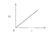
また、この圧力制御弁30は、図3にグラフで表されているように、ソレノイド吸引力F1 の大きさがソレノイド74の励磁電流Iの大きさに応じてリニアに変化するように設計されている。
【0025】
図1に示すように、圧力制御弁30にはバイパス通路82が設けられており、そのバイパス通路82の途中にチェック弁84が設けられている。万が一、ブレーキペダル10の踏み込み時に圧力制御弁30内の可動部材に生ずる流体力によって圧力制御弁30が閉じることがあっても、マスタシリンダ14からブレーキシリンダ20へ向かう作動液の流れが確保されるようにするためである。圧力制御弁30にはさらに、それに並列にリリーフ弁86も設けられている。ポンプ40による吐出圧が過大となることを防止するためである。
【0026】
前記各分岐通路26の途中には常開の電磁開閉弁である増圧弁90が設けられ、開状態でマスタシリンダ14からブレーキシリンダ20へ向かう作動液の流れを許容する増圧状態を実現する。各増圧弁90にはバイパス通路92が接続され、各バイパス通路92には作動液戻り用のチェック弁94が設けられている。各分岐通路26のうち増圧弁90とブレーキシリンダ20との間の部分からリザーバ通路96が延びてリザーバ98に至っている。各リザーバ通路96の途中には常閉の電磁開閉弁である減圧弁100が設けられ、開状態でブレーキシリンダ20からリザーバ98へ向かう作動液の流れを許容する減圧状態を実現する。リザーバ98は、ハウジングにリザーバピストン104が実質的に気密かつ摺動可能に嵌合されて構成されるとともに、その嵌合によって形成されたリザーバ室106において作動液を弾性部材としてのスプリング108によって圧力下に収容するものである。
【0027】
リザーバ98は吸入通路110によって前記ポンプ40の吸入側に接続され、ポンプ40の吐出側は吐出通路114によって主通路18のうち圧力制御弁30と増圧弁90との間の部分に接続されている。吸入通路110にはチェック弁である吸入弁116、吐出通路114にはチェック弁である吐出弁118がそれぞれ設けられている。吐出通路114にはさらに、絞りとしてのオリフィス120と固定ダンパ122とがそれぞれ設けられており、それらにより、ポンプ40の脈動が軽減される。
【0028】
ところで、効き特性制御の実行中には、ポンプ40がリザーバ98から作動液を汲み上げ、その作動液を各ブレーキシリンダ20に吐出することによって各ブレーキシリンダ20が増圧されるが、アンチロック制御が実行されていない場合には、リザーバ98に汲み上げるべき作動液が存在しないのが普通であり、効き特性制御の実行を確保するためには、アンチロック制御の実行の有無を問わず、リザーバ98に作動液を補給することが必要となる。そのため、本実施形態においては、基幹通路24のうちマスタシリンダ14と圧力制御弁30との間の部分から延びてリザーバ98に至る補給通路130が設けられている。しかし、この補給通路130により常時マスタシリンダ14とリザーバ98とを互いに連通させたのでは、ブレーキペダル10が踏み込み操作されても、リザーバ98においてリザーバピストン104がボトミングした後でないとマスタシリンダ14が昇圧することができず、ブレーキの効き遅れが生じる。また、アンチロック制御中、ポンプ40は作動液をリザーバ98からではなくマスタシリンダ14から汲み上げてしまい、リザーバ98による減圧機能が阻害される。
【0029】
そこで、本実施形態においては、補給通路130の途中に流入制御弁140が設けられている。流入制御弁140は、マスタシリンダ14からリザーバ98への作動液の補給が必要であるときには開状態となり、マスタシリンダ14からリザーバ98への作動液の流れを許容し、一方、マスタシリンダ14からリザーバ98への作動液の補給が必要ではないときには閉状態となり、マスタシリンダ14からリザーバ98への作動液の流れを阻止し、マスタシリンダ14による昇圧を可能とする。本実施形態においては、流入制御弁140が常閉の電磁開閉弁とされている。また、本実施形態においては、マスタシリンダ14から作動液を導入することが必要である場合であるか否かの判定が、アンチロック制御中、リザーバ98においてポンプ40により汲み上げるべき作動液が存在しないか否かの判定とされ、また、その作動液の存否判定が、増圧弁90が増圧状態にある時間の積算値と、減圧弁100が減圧状態にある時間の積算値とがそれぞれ演算されるとともに、それら増圧時間と減圧時間とに基づいてリザーバ98における作動液の残量が推定されることにより、行われる。
【0030】
ブレーキ操作中、主通路18のうち圧力制御弁30より上流側の部分内の作動液を利用してポンプ40による作動液の加圧を行う際、その上流側部分内の高圧の作動液をリザーバ98により低圧にしてポンプ40により汲み上げるより、リザーバ98により低圧にしないで汲み上げる方が、ポンプ40の作動応答性が向上するとともに、ポンプ40の負担軽減によってポンプ40の低能力化が容易となる。
【0031】
そこで、本実施形態においては、吸入通路110のうち補給通路130との接続点とリザーバ通路96との接続点との間の部分に、補給通路130からリザーバ98に向かう作動液の流れを阻止し、その逆向きの流れを許容するチェック弁142が設けられている。
【0032】
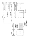
図4には、ブレーキ装置の電気的構成が示されている。ブレーキ装置は、CPU,ROMおよびRAMを含むコンピュータを主体とするECU(電子制御ユニット)150を備えている。ROMに効き特性制御ルーチン(図5にフローチャートで表されている),流入制御弁制御ルーチン(図6にフローチャートで表されている),アンチロック制御ルーチン(図示しない)および推定車速演算ルーチン(図示しない)を始めとする各種ルーチンが記憶されており、それらルーチンがCPUによりRAMを使用しつつ実行されることにより、効き特性制御とアンチロック制御とがそれぞれ実行される。
【0033】
ECU150の入力側には、イグニションスイッチ162,ブースタ負圧スイッチ164,マスタシリンダ液圧センサ166および車輪速センサ168が接続されている。
【0034】
イグニションスイッチ162は、運転者により操作可能な位置として「OFF」,「ACC」,「ON」および「START」を備えており、操作された各操作位置を規定するイグニション信号を出力する。このイグニションスイッチ162は、運転者により「OFF」位置,「ACC」位置,「ON」位置および「START」位置の順に操作されるように構成されている。そして、イグニションスイッチ162が「ON」位置に操作されたことに応じてECU150のコンピュータの電源が投入され、コンピュータが上記各種ルーチンの実行を開始する。また、イグニションスイッチ162が続いて「START」位置に操作されれば、エンジンのクランキングが行われてエンジンが始動させられる。エンジン始動後に運転者がイグニションスイッチ162から手を離せば、「ON」位置に自動的に戻り、その後、運転者による操作が加えられない限り、イグニションスイッチ162は「ON」位置に保持される。
【0035】
ブースタ負圧スイッチ164は、ブースタ12の変圧室12aの負圧が基準値より低い状態(負圧不足状態)ではOFF状態のブースタ負圧信号(第1信号)を出力し、基準値以上である状態(負圧正常状態)ではON状態のブースタ負圧信号(第2信号)を出力する。本実施形態においては、ブースタ負圧スイッチ164が「ブースタ圧力センサ」の一例を構成している。
【0036】
マスタシリンダ液圧センサ166は、マスタシリンダ液圧を検出し、マスタシリンダ液圧の高さを規定するマスタシリンダ液圧信号であってマスタシリンダ液圧が連続的に変化するのに応じて連続的に変化するものを出力する。
【0037】
車輪速センサ168は、各輪毎に設けられ、各輪の車輪速を規定する車輪速信号を出力する。
【0038】
一方、ECU150の出力側には、前記ポンプ40を駆動するポンプモータ170が接続され、そのポンプモータ170にモータ駆動信号が出力される。ECU150の出力側にはさらに、前記圧力制御弁30のソレノイド74,流入制御弁140,増圧弁90および減圧弁100の各ソレノイド174も接続されている。圧力制御弁30のソレノイド74には、ソレノイド74の磁気力をリニアに制御するための電流制御信号が出力され、一方、流入制御弁140,増圧弁90および減圧弁100の各ソレノイド174にはそれぞれ、ソレノイド174をON/OFF駆動するためのON/OFF駆動信号が出力される。
【0039】
また、コンピュータは、イグニションスイッチ162が「ON」位置に操作されたときから経過した経過時間tを計測するタイマを備えている。
【0040】
ここで、ECU150による効き特性制御を詳細に説明するが、まず、概略的に説明する。
【0041】
ブースタ12は、ブレーキペダル10の踏力Fがある値まで増加すると、変圧室12bの圧力が大気圧まで上昇し切ってしまい、助勢限界に達する。助勢限界後は、ブースタ12は踏力Fを助勢することができないから、何ら対策を講じないと、図7にグラフで表されているように、ブレーキの効き、すなわち、同じ踏力Fに対応するブレーキシリンダ液圧PB の高さが助勢限界がないと仮定した場合におけるブレーキシリンダ液圧PB の高さより低下する。かかる事実に着目して効き特性制御が行われるのであり、具体的には、図8にグラフで表されているように、ブースタ12が助勢限界に達した後には、ポンプ40を作動させてマスタシリンダ液圧PM より差圧ΔP(ブレーキシリンダ液圧PB のマスタシリンダ液圧PM に対する増圧量)だけ高い液圧をブレーキシリンダ20に発生させ、それにより、ブースタ12の助勢限界の前後を問わず、ブレーキの効きを安定させる。ここに、差圧ΔPとマスタシリンダ液圧PM との関係は例えば、図9にグラフで表されるものとされる。
【0042】
しかし、ブースタ12は常に正常に作動するとは限らない。ブースタ12におけるシールの損傷や前記バキュームホースの損傷などを原因として、負圧室12aの負圧が基準値に到達しないこと、すなわち、ブースタ12が失陥状態に陥ることがあるからである。このような場合には、ポンプ40の作動開始条件をブースタ12が正常である場合におけるより緩くし、容易にポンプ40の作動が開始されるようにすることが車両制動力を増加させるために望ましい。そのようなポンプ40の作動開始制御を実現するために、本実施形態においては、ポンプ40の作動を開始させるために実マスタシリンダ液圧PM が超えなければならない基準マスタシリンダ液圧PM0が、ブースタ12が正常である場合におけるより低く決定される。例えば、図10にグラフで表されているように、基準マスタシリンダ液圧PM0がブースタ12の失陥時において正常時におけるより低くされ、具体的には、失陥時には0、正常時にはA(>0)とされている。
【0043】
ところで、前述のように、各回の車両運転当初において、必ず負圧室12aに十分に高い負圧が残っているとは限らず、負圧室12aの負圧が基準値に到達しない場合がある。この場合には、特別な対策を講じない限り、今回の車両運転当初に、ECU150のコンピュータによって基準マスタシリンダ液圧PM0が0に決定される。
一方、運転者は、車両運転当初において、ブレーキペダル10を踏み込んでマスタシリンダ14に液圧を発生させた状態でイグニションスイッチ162を「ON」位置に操作するのが普通であり、よって、マスタシリンダ14に液圧が発生している状態でコンピュータが動作を開始することになるのが普通である。
【0044】
そのため、今回の車両運転当初に、実マスタシリンダ液圧PM が基準マスタシリンダ液圧PM0を超えてしまい、ポンプ40が作動を開始させられる。しかし、車両運転当初には、普通、それほど大きな車両制動力が必要とされるわけではないため、ポンプ40が無駄に作動させられることとなり、ポンプ40の作動音によって車両の静粛性が損なわれる。また、本実施形態においては、ポンプ40は作動時、マスタシリンダ14から作動液を吸入するため、運転者が踏力Fを増加させようとしているわけではないにもかかわらずブレーキペダル10の操作位置が深くなってしまい、ブレーキ操作フィーリングが悪化する。
【0045】
そこで、本実施形態においては、負圧室12aの負圧が0である状態(大気圧である状態)でエンジンを始動させた場合に負圧が正常値まで上昇するのに必要な時間を予め実験的に取得し、その昇圧所要時間が経過していないうちは、図10にグラフで表されているように、基準マスタシリンダ液圧PM0が0より高い高さBに決定され、それにより、基準マスタシリンダ液圧PM0が0に決定された場合におけるより容易にはポンプ40の作動が開始されないようになっている。
【0046】
具体的には、昇圧所要時間が経過していないか否かの判定が、イグニションスイッチ162が「ON」に操作されたときから設定時間Tが経過していないか否かの判定とされている。ここに、設定時間Tは、昇圧所要時間と等しく設定されている。イグニションスイッチ162が「OFF」位置から「ON」位置に操作された時期とエンジンの始動時期とは厳密には一致せず、また、多少の差を許容して比較しても、常に一致するとは限らないが、一般的には、互いに接近していると考えることができるからである。
【0047】
また、基準マスタシリンダ液圧PM0の高さBが、ブースタ12が正常である場合における高さAより高く設定されている。ただし、高さAと等しく設定したり、0より高く、かつ、高さAより低く設定することができる。
【0048】
しかし、設定時間Tの経過前において常に運転者がブレーキペダル10を軽く踏み込むとは限らず、かなり大きい車両制動力を得ようとしてかなり強く踏み込む場合も考えられる。設定時間Tの経過前に車両が実際に走行を開始し、その後に車両を急に減速したり、完全に停止させたりするためにブレーキペダル10を踏み込む場合もあるからである。
【0049】
そこで、本実施形態においては、車両が停止状態から走行状態に移行したと判定されたときには、経過時間Tの経過前であっても、ブースタ負圧スイッチ164の出力信号に基づく基準マスタシリンダ液圧PM0の決定が許可され、ポンプ40の作動開始が容易に行われるようになっている。
【0050】
すなわち、本実施形態においては、設定時間Tの経過前であるという第1条件(「車両運転の開始が検出された時期から基準時間が経過していない時期であるという第1条件」の一例)と、車両が停止状態にあるという第2条件とが同時に成立した場合において同時に成立しない場合におけるより、基準マスタシリンダ液圧PM0が高くなるように決定され、それにより、ポンプ40の作動開始が困難となるようにされているのである。
【0051】
以上概略的に説明した効き特性制御の内容を図5および図6のルーチンに基づいて具体的に説明する。
【0052】
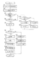
図5の効き特性制御ルーチンは、運転者によりイグニションスイッチ162が「ON」位置に操作された後、繰り返し実行される。各回の実行時にはまず、ステップS1(以下、単に「S1」で表す。他のステップについても同じとする。)において、マスタシリンダ液圧センサ166からマスタシリンダ液圧信号が取り込まれ、次に、S2において、ブースタ負圧スイッチ164からブースタ負圧信号が取り込まれる。
【0053】
その後、S3において、前記タイマにより計時された経過時間tに基づき、イグニションスイッチ162が「ON」に操作されたときから設定時間Tが経過していない(t<T)か否かが判定される。今回は設定時間Tが経過していないと仮定すれば、判定がYESとなり、S4において、車両が停止状態にあるか否かが判定される。具体的には、車速Vが基準値V0 (例えば、5km/h)より低いか否かが繰り返し判定され、車速Vが基準値V0 より低い状態が一定時間連続したときに、車両が停止状態にあると判定される。なお、車速Vは、前記推定車速演算ルーチンにより、前記車輪速センサ168の出力信号に基づく4輪の車輪速に基づいて演算された推定車速として取得される。今回は車両が停止状態にあると仮定すれば、判定がYESとなり、S5において、基準マスタシリンダ液圧PM0が高さBに決定される。
【0054】
これに対して、設定時間Tの経過後であるためにS3の判定がNOとなるか、または、設定時間Tの経過前であるが、車両が走行状態に移行したためにS3の判定はYES、S4の判定はNOとなれば、S16において、ブースタ負圧スイッチ164がONであるか否か、すなわち、負圧室12aにおいて負圧が正常な高さで発生しているか否かが判定される。今回はブースタ負圧スイッチ164がONであると仮定すれば、判定がYESとなり、S17において、ブースタ12が正常であると判定され、S18において、基準マスタシリンダ液圧PM0が高さAに決定される。これに対して、今回はブースタ負圧スイッチ164がOFFであると仮定すれば、S16の判定がNOとなり、S19において、ブースタ12が失陥していると判定され、S20において、基準マスタシリンダ液圧PM0が0に決定される。
【0055】
いずれの場合にも、その後、S6において、ブースタ12が助勢限界に到達したか否かが判定される。具体的には、マスタシリンダ液圧信号に基づく実マスタシリンダ液圧PM が基準マスタシリンダ液圧PM0を超えたか否かが判定される。今回は超えていないと仮定すれば、判定がNOとなり、S7において、圧力制御弁30のソレノイド74にそれをOFFする信号が出力され、それにより、圧力制御弁30が開状態とされる。続いて、S8において、流入制御弁140のソレノイド174にそれをOFFする信号が出力され、それにより、流入制御弁140が閉状態とされる。その後、S9において、ポンプモータ170にそれをOFFする信号が出力される。以上で本ルーチンの一回の実行が終了する。
【0056】
これに対して、今回は実マスタシリンダ液圧PM が基準マスタシリンダ液圧PM0を超えたと仮定すれば、S6の判定がYESとなり、S11において、マスタシリンダ液圧PM の現在値の、基準マスタシリンダ液圧PM0からの増分IPM に応じて目標差圧ΔPが演算される。増分IPM と目標差圧ΔPとの関係がROMに記憶されており、その関係に従って現在のマスタシリンダ液圧PM に対応する目標差圧ΔPが決定されるのである。その関係は例えば、図11にグラフで表されているように、増分IPM が増加するにつれて目標差圧ΔPが0からリニアに増加する関係とされる。
【0057】
続いて、S12において、圧力制御弁30のソレノイド74につき、目標差圧ΔPに応じたソレノイド電流値Iが演算される。目標差圧ΔPとソレノイド電流値Iとの関係がROMに記憶されており、その関係に従って目標差圧ΔPに対応するソレノイド電流値Iが演算されるのである。続いて、S13において、そのソレノイド電流値Iで励磁電流がソレノイド74に供給されることにより、圧力制御弁30が制御される。その後、S14において、流入制御弁140が制御される。
【0058】
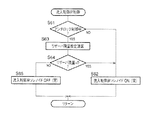
このS14の詳細が図6に流入制御弁制御ルーチンとしてフローチャートにより表されている。
【0059】
まず、S61において、現在アンチロック制御の実行中であるか否かが判定される。実行中ではないと仮定すれば判定がNOとなり、S62において、流入制御弁140のソレノイド174にそれをONする信号、すなわち、流入制御弁140を開かせるための信号が出力される。これにより、マスタシリンダ14から作動液が補給通路130を経てポンプ40に導入可能となる。以上で本ルーチンの一回の実行が終了する。
【0060】
これに対し、現在アンチロック制御の実行中であると仮定すればS61の判定がYESとなり、S63において、リザーバ98においてポンプ40により汲み上げるべき作動液として存在する作動液の量の推定演算、すなわち,リザーバ残量の推定演算が行われる。続いて、S64において、推定されたリザーバ残量が0であるか否か、すなわち、リザーバ98においてポンプ40により汲み上げるべき作動液が存在しないか否かが判定される。今回はリザーバ残量が0ではないと仮定すれば、判定がNOとなり、S65において、流入制御弁140のソレノイド174にそれをOFFする信号、すなわち、流入制御弁140を閉じさせるための信号が出力される。一方、今回はリザーバ残量が0であると仮定すれば、S64の判定がYESとなり、S62において、流入制御弁140にそれを開かせるための信号が出力される。いずれの場合も、以上で本ルーチンの一回の実行が終了し、図5のS15に移行する。
【0061】
このS15においては、ポンプモータ170にそれをONする信号が出力され、これにより、ポンプ40によりリザーバ98から作動液が汲み上げられ、作動液が各ブレーキシリンダ20に吐出される。これにより、各ブレーキシリンダ20がマスタシリンダ液圧PM より目標差圧ΔPだけ高い液圧が発生させられる。以上で本ルーチンの一回の実行が終了する。
【0062】
前記アンチロック制御ルーチンは、車輪速センサ168により各輪の車輪速および車速を監視しつつ、増圧弁90は開状態、減圧弁100は閉状態とする増圧状態,増圧弁90も減圧弁100も閉状態とする保持状態および増圧弁90は閉状態、減圧弁100は開状態とする減圧状態を選択的に実現することにより、車両制動時に各輪がロックすることを防止する。さらに、アンチロック制御ルーチンは、アンチロック制御中ポンプモータ170を作動させ、ポンプ40によりリザーバ98から作動液を汲み上げて主通路18に戻す。
【0063】
このアンチロック制御ルーチンは、効き特性制御ルーチンの実行の有無を問わず実行される。したがって、効き特性制御の実行中であって、各輪のロック傾向が過大となれば、アンチロック制御ルーチンが実行され、その結果、各輪のブレーキの作動力が過大にならずに済む。
【0064】
したがって、本実施形態によれば、車両運転当初においてポンプ40が必要でないにもかかわらず作動させられることが防止されるため、ポンプ40の作動音の増加やブレーキペダル10の操作ストロークの増加が防止されるという効果が得られる。
【0065】
さらに、本実施形態によれば、車両運転当初であっても、大きな車両制動力が必要である場合には、負圧室12aにおける負圧上昇を待つことなくポンプ40が作動させられてブレーキシリンダ20が増圧されるため、車両の制動性能の低下を回避しつつ車両の静粛性やペダル操作フィーリングの低下が回避されるという効果が得られる。
【0066】
以上の説明から明らかなように、本実施形態においては、イグニションスイッチ162が請求項1における「運転開始検出手段」の一例を構成し、前記タイマと、ECU150のうち図5のS3〜S5を実行する部分が「作動開始制御手段」の一例を構成するとともに、請求項2における「作動開始条件決定手段」の一例を構成しているのである。また、車輪速センサ168と、ECU150のうち図のS4および推定車速演算ルーチンを実行する部分とが互いに共同して請求項3における「車両停止状態検出手段」の一例を構成しているのである。また、圧力制御弁30と、ポンプ40と、リザーバ98と、補給通路130と、流入制御弁140と、マスタシリンダ液圧センサ166と、ECU150のうち図5のS1,S2,S6〜S9およびS11〜S20ならびに図6のルーチンを実行する部分とが互いに共同して請求項5における「増圧装置」の一例を構成するとともに、請求項1における「ブレーキ作動力増加装置」の一例を構成しているのである。
【0067】
なお付言すれば、図6の流入制御弁制御ルーチンにつき、リザーバ98における作動液の残量を直接センサにより検出する改良を加えることができる。残量は例えば、リザーバ98におけるリザーバピストン104に永久磁石を一体的に移動可能に設け、それに近接してセンサとしてのリードスイッチを設けることにより検出することができる。
【0068】
図12には、別の実施形態における効き特性制御ルーチンが示されている。なお、本実施形態は、先の実施形態と効き特性制御ルーチンのみが異なり、他の部分は共通であるため、効き特性制御ルーチンのみを詳細に説明し、他の部分については詳細な説明を省略する。また、その効き特性制御ルーチンについては、先の実施形態におけるものと共通するステップがあるため、共通するステップについては同一の符号を使用することによって詳細な説明を省略し、異なるステップについてのみ詳細に説明する。
【0069】
本実施形態においては、S2の実行後、S30において、ブースタ負圧スイッチ164がON(負圧正常)であるか否かが判定される。今回はONではないと仮定すれば、判定がNOとなり、S31において、イグニションスイッチ162が「ON」位置に操作されたときから設定時間Tが経過していないか否かが判定される。今回は経過していないと仮定すれば、判定がYESとなり、S32において、車両が実質的に停止状態にあるか否かが判定される。今回は停止状態にあると仮定すれば、判定がYESとなり、S33において、基準マスタシリンダ液圧PM0が高さBに決定される。その後、S6以下に移行する。
【0070】
これに対して、ブースタ負圧スイッチ164がOFFであり、かつ、設定時間Tの経過後である場合には、S30の判定はNO、S31の判定もNOとなり、S34において、ブースタ12が失陥していると判定される。その後、S35において、基準マスタシリンダ液圧PM0が0に決定される。その後、S6以下に移行する。
【0071】
また、ブースタ負圧スイッチ164がOFFであり、かつ、設定時間Tの経過前であり、かつ、車両が走行状態に移行した場合には、S30の判定はNO、S31の判定はYES、S32の判定はNOとなり、この場合にも、S35において、基準マスタシリンダ液圧PM0が0に決定される。その後、S6以下に移行する。
【0072】
また、ブースタ負圧スイッチ164がONである場合には、S30の判定がYESとなり、S36において、ブースタ12が正常であると判定され、S37において、基準マスタシリンダ液圧PM0が高さAに決定される。その後、S6以下に移行する。
【0073】
したがって、本実施形態においては、設定時間Tの経過前において、一律に基準マスタシリンダ液圧PM が高さBとされるのではなく、負圧室12aに正常な高さが負圧が発生している場合には、基準マスタシリンダ液圧PM0がブースタ12が正常である場合の高さAとされ、発生していない場合に限って、基準マスタシリンダ液圧PM が高さBとされる。しかし、それら高さAおよびBはいずれも、0より高いため、設定時間Tの経過前に、ポンプ40の作動が容易に開始されることはない。
【0074】
すなわち、本実施形態においては、設定時間Tの経過前であるという第1条件と、車両が停止状態にあるという第2条件と、負圧室12aの負圧が不足しているという第3条件とが同時に成立した場合において、同時に成立しない場合におけるより、基準マスタシリンダ液圧PM0が高く決定され、それにより、ポンプ40の作動開始が困難となるようにされているのである。
【0075】
以上の説明から明らかなように、本実施形態においては、イグニションスイッチ162が請求項1における「運転開始検出手段」の一例を構成し、前記タイマと、ECU150のうち図12のS31〜S33を実行する部分とが互いに共同して「作動開始制御手段」の一例を構成するとともに、請求項2における「作動開始条件決定手段」の一例を構成しているのである。
【0076】
図13には、さらに別の実施形態における効き特性制御ルーチンが示されている。なお、本実施形態も、最先の実施形態と異なる部分についてのみ詳細に説明する。
【0077】
本実施形態においては、S2の実行後、S40において、ブースタ負圧スイッチ164がON(負圧正常)であるか否かが判定される。今回はONではないと仮定すれば、判定がNOとなり、S41において、イグニションスイッチ162が「ON」位置に操作されたときから設定時間Tが経過していないか否かが判定される。今回は経過していないと仮定すれば、判定がYESとなり、S42において、車両が停止状態にあるか否かが判定される。今回は停止状態にあると仮定すれば、判定がYESとなり、直ちに、S7以下に移行し、ポンプ40の作動が禁止される。
【0078】
これに対して、ブースタ負圧スイッチ164がOFFであり、かつ、設定時間Tの経過後である場合には、S40の判定はNO、S41の判定もNOとなり、S43において、ブースタ12が失陥していると判定される。その後、S44において、基準マスタシリンダ液圧PM0が0に決定される。その後、S6以下に移行する。
【0079】
また、ブースタ負圧スイッチ164がOFFであり、かつ、設定時間Tの経過前であり、かつ、車両が走行状態に移行した場合には、S40の判定はNO、S41の判定はYES、S42の判定はNOとなり、この場合にも、S44において、基準マスタシリンダ液圧PM0が0に決定される。その後、S6以下に移行する。
【0080】
また、ブースタ負圧スイッチ164がONである場合には、S40の判定がYESとなり、S45において、ブースタ12が正常であると判定され、S46において、基準マスタシリンダ液圧PM0が高さAに決定される。その後、S6以下に移行する。
【0081】
したがって、本実施形態においては、負圧室12aの負圧が不足しており、かつ、設定時間Tの経過前であり、かつ、車両が停止状態にある場合には、基準マスタシリンダ液圧PM0の決定も、実マスタシリンダ液圧PM と基準マスタシリンダ液圧PM0との比較も行われることなく、直ちに、ポンプ40の作動が禁止される。
【0082】
すなわち、本実施形態においては、設定時間Tの経過前であるという第1条件と、車両が停止状態にあるという第2条件と、負圧室12aの負圧が不足しているという第3条件とが同時に成立した場合において、ポンプ40の作動開始が禁止されるようにされているのである。
【0083】
以上の説明から明らかなように、本実施形態においては、イグニションスイッチ162が請求項1における「運転開始検出手段」の一例を構成し、前記タイマと、ECU150のうち図13のS41およびS42を実行する部分とが互いに共同して「作動開始制御手段」の一例を構成するとともに、請求項3における「作動開始禁止手段」の一例を構成しているのである。
【0084】
さらに別の実施形態を説明する。
以上説明した実施形態においてはいずれも、イグニションスイッチ162が「ON」位置に操作されれば普通、直ちにエンジンが始動されるという事実に基づき、設定時間Tと比較される経過時間tが、イグニションスイッチ162が「ON」位置に操作される時期から計測されている。しかし、常にそのような事実が成立するとは限らない。
【0085】
そこで、本実施形態においては、図14に示すように、エンジンが始動したことを検出するエンジン始動センサ200が追加され、また、図15にフローチャートで表すように、ROMに経過時間計測ルーチンが追加されることにより、経過時間tがエンジンの始動時期から計測されるようになっている。
【0086】
エンジン始動センサ200は例えば、エンジンの回転数(回転速度)を検出するエンジン回転数センサを含み、そのエンジン回転数センサにより検出されたエンジン回転数が基準値(例えば、500rpm)以上となったため、エンジンが自立回転可能となったときに、エンジンの始動を検出する態様とすることができる。
【0087】
図15の経過時間計測ルーチンは、イグニションスイッチ162が「ON」に操作された後、一定の周期Δtで繰り返し実行される。各回の実行時にはまず、S101において、エンジン始動センサ200から、エンジンが始動したか否かを表すエンジン始動信号が取り込まれる。次に、S102において、そのエンジン始動信号に基づき、エンジンの始動後であるか否かが判定される。始動前であると仮定すれば、判定がNOとなり、S103において、経過時間tを0にするための信号が出力される。これに対して、エンジンの始動後であると仮定すると、S102の判定がYESとなり、S104において、経過時間tが実行周期Δtだけ増加させられる。このようにして本ルーチンの実行が繰り返されることにより、エンジンが始動したときからの経過時間tが計測される。
【0088】
そのようにして計測された経過時間tは設定時間Tと比較され、その結果に基づいてポンプ40の作動開始が制御される。
【0089】
以上の説明から明らかなように、本実施形態においては、エンジン始動センサ200が請求項1における「運転開始検出手段」の一例を構成し、ECU150のうち図5のS3〜S5および図15の経過時間計測ルーチンを実行する部分が「作動開始制御手段」の一例を構成するとともに、請求項2における「作動開始条件決定手段」の一例を構成しているのである。
【0090】
さらに別の実施形態を説明する。
以上説明した実施形態においてはいずれも、ブレーキ操作中(ただし、アンチロック制御中を除く。)において、ポンプ40を作動させる必要性の有無が、ブースタ12の負圧室12aの圧力を検出する前記ブースタ負圧スイッチ164と前記マスタシリンダ液圧センサ166との双方によって判定されるようになっているが、本実施形態においては、図16に示すように、ブースタ負圧スイッチ164に代えて、変圧室12bの圧力が基準値となったことを検出するブースタ圧力スイッチ210が設けられている。ブースタ圧力スイッチ210は、変圧室21bの圧力が基準値より低い状態ではOFF状態のブースタ圧力信号を出力し、基準値以上の状態では、ON状態のブースタ圧力信号を出力する。
【0091】
このブースタ圧力スイッチ210は、大気圧を基準値として、変圧室12bの圧力がその基準値より負圧であるかによって異なる信号を出力する形式とすることができ、このようにした場合には、ブースタ圧力スイッチ210が変圧室12bの圧力がその基準値であることを検出したときに、ポンプ作動必要性があると判定することができる。したがって、この場合には、ブースタ圧力スイッチ210単独でポンプ作動必要性判定が可能となる。また、ブースタ圧力スイッチ210は、大気圧より低い負圧を基準値として、変圧室12bの圧力がその基準値より負圧であるかによって異なる信号を出力する形式とすることもでき、このようにした場合には、マスタシリンダ液圧センサ166により検出された実マスタシリンダ液圧PM の、変圧室12bの圧力が基準値に達したときからの実際の増加量が、変圧室12bの圧力がその基準値から大気圧まで増加するまでに増加すると予想される量と等しくなったときに、ポンプ作動必要性があると判定することができる。したがって、この場合には、ブースタ圧力スイッチ210とマスタシリンダ液圧センサ166との双方によってポンプ作動必要性判定が可能となる。
【0092】
図17には、本実施形態における効き特性制御ルーチンが示されている。なお、本ルーチンのうち、図5のルーチンと共通する要素については簡単に説明する。
【0093】
まず、S201において、マスタシリンダ液圧センサ166からマスタシリンダ液圧信号が取り込まれ、次に、S202において、ブースタ圧力スイッチ210からブースタ圧力信号が取り込まれる。その後、S203において、前記タイマにより計時された経過時間tに基づき、イグニションスイッチ162が「ON」に操作されたときから設定時間Tが経過していないか否かが判定される。今回は経過していないと仮定すれば、判定がYESとなり、S204において、車両が停止状態にあるか否かが判定される。今回は停止状態にあると仮定すれば、判定がYESとなり、S205以下に移行する。
【0094】
S205においては、圧力制御弁30のソレノイド74にそれをOFFする信号が出力され、それにより、圧力制御弁30が開状態とされる。続いて、S206において、流入制御弁140のソレノイド174にそれをOFFする信号が出力され、それにより、流入制御弁140が閉状態とされる。その後、S207において、ポンプモータ170にそれをOFFする信号が出力される。以上で本ルーチンの一回の実行が終了する。
【0095】
これに対して、設定時間Tの経過後であるためにS203の判定がNOとなるか、または、設定時間Tの経過前であるが、車両が走行状態に移行しためにS203の判定はYES、S204の判定はNOとなれば、S208において、前述のポンプ作動必要性判定の原理に基づき、ブースタ圧力スイッチ210のブースタ圧力信号とマスタシリンダ液圧センサ166のマスタシリンダ液圧信号とのうち少なくともブースタ圧力信号に基づき、ポンプ作動必要性が判定される。今回はポンプ作動必要性がないと仮定すれば、判定がNOとなり、S205以下に移行するが、今回はポンプ作動必要性があると仮定すれば、判定がYESとなり、S209以下に移行する。
【0096】
S209においては、マスタシリンダ液圧PM の現在値の、ポンプ作動必要性があると判定されたときの値PM1からの増分IPM に応じて目標差圧ΔPが演算される。続いて、S210において、圧力制御弁30のソレノイド74につき、目標差圧ΔPに応じたソレノイド電流値Iが演算され、S211において、その演算されたソレノイド電流値Iで励磁電流がソレノイド74に供給されることにより、圧力制御弁30が制御され、S212において、流入制御弁140が制御される。その後、S213において、ポンプモータ170にそれをONする信号が出力される。以上で本ルーチンの一回の実行が終了する。
【0097】
なお付言すれば、先の実施形態においては、ポンプ作動必要性が基本的にはブースタ12が正常である場合と失陥した場合との2つの場合に分けて判定されるようになっているが、本実施形態においては、ポンプ作動必要性が基本的には負圧室12aの圧力の実際値の連続的変化を考慮して判定されるようになっている。このことは、先の実施形態においては、基準マスタシリンダ液圧PM0がAと0というように大きさが不連続に変化するのに対して、本実施形態においては、その基準マスタシリンダ液圧PM0に相当する値PM1が、負圧室12aの圧力の実際値に応じて大きさが連続的に変化するという相違点として現れている。したがって、本実施形態によれば、ブースタ12の実際の助勢特性を決める一変数である負圧室12aの圧力の実際値に正確に追従した効き特性制御が可能となるという効果が得られる。
【0098】
さらに付言すれば、本実施形態においては、ポンプ作動必要性を基本的には負圧室12aの圧力の実際値の連続的変化を考慮して判定するために、ブースタ圧力スイッチ210が設けられているが、負圧室12aの圧力を検出し、かつ、その圧力が連続的に変化するのに応じて連続的に変化する信号を出力するブースタ圧力センサをブースタ圧力センサ210に代えて用いることはもちろん可能である。
【0099】
以上の説明から明らかなように、本実施形態においては、ブースタ圧力スイッチ210が請求項1における「ブースタ圧力センサ」の一例を構成し、イグニションスイッチ162が「運転開始検出手段」の一例を構成し、前記タイマと、ECU150のうち図17のS203およびS204を実行する部分とが互いに共同して「作動開始制御手段」の一例を構成するとともに、請求項3における「作動開始禁止手段」の一例を構成しているのである。
【0100】
以上、本発明のいくつかの実施形態を図面に基づいて詳細に説明したが、それらの他にも、特許請求の範囲を逸脱することなく、当業者の知識に基づいて種々の変形,改良を施した形態で本発明を実施することができるのはもちろんである。
【図面の簡単な説明】
【図1】本発明の一実施形態であるブレーキ装置を示す系統図である。
【図2】図1における圧力制御弁30の構造および作動を説明するための正面断面図である。
【図3】図2の圧力制御弁におけるソレノイド励磁電流Iとソレノイド吸引力F1 との関係を示すグラフである。
【図4】上記ブレーキ装置の電気的構成を示すブロック図である。
【図5】図4におけるROMに記憶されているブレーキ効き特性制御ルーチンを示すフローチャートである。
【図6】図5におけるS8の詳細を流入制御弁制御ルーチンとして示すフローチャートである。
【図7】バキュームブースタを備えた一般的なブレーキ装置におけるブレーキ操作力Fとブレーキシリンダ液圧PB との関係を示すグラフである。
【図8】上記実施形態であるブレーキ装置におけるブレーキ効き特性制御を説明するためのグラフである。
【図9】そのブレーキ効き特性制御におけるマスタシリンダ液圧PM とマスタシリンダとブレーキシリンダとの差圧ΔPとの関係を示すグラフである。
【図10】そのブレーキ効き特性制御におけるマスタシリンダ液圧PM と上記差圧ΔPとの関係がブースタの失陥時と正常時とエンジン始動当初とで互いに異なる様子を示すグラフである。
【図11】図5のS11におけるマスタシリンダ液圧PM の増分IPM と上記差圧ΔPとの関係を示すグラフである。
【図12】本発明の別の実施形態であるブレーキ装置におけるブレーキ効き特性制御ルーチンを示すフローチャートである。
【図13】本発明のさらに別の実施形態であるブレーキ装置におけるブレーキ効き特性制御ルーチンを示すフローチャートである。
【図14】本発明のさらに別の実施形態であるブレーキ装置の電気的構成を示すブロック図である。
【図15】図14におけるECUのコンピュータにより実行される経過時間計測ルーチンを示すフローチャートである。
【図16】本発明のさらに別の実施形態であるブレーキ装置を示す系統図である。
【図17】そのブレーキ装置におけるブレーキ効き特性制御ルーチンを示すフローチャートである。
【符号の説明】
10 ブレーキペダル
12 ブースタ
14 マスタシリンダ
20 ブレーキシリンダ
30 圧力制御弁
40 ポンプ
150 ECU
162 イグニションスイッチ
164 ブースタ負圧スイッチ
166 マスタシリンダ液圧センサ
168 車輪速センサ
200 エンジン始動センサ
210 ブースタ圧力スイッチ[0001]
BACKGROUND OF THE INVENTION
The present invention relates to a brake device for a vehicle, and more particularly to a brake device provided with a vacuum booster.
[0002]
[Background]
The brake device is generally provided in a vehicle having a prime mover, such as an internal combustion engine, an electric motor, etc., (a) a brake operation member such as a brake pedal, and (b) a negative pressure source that starts generating negative pressure in response to the start of the prime mover. (C) The brake operating member is moved by the operating force of the power piston based on the differential pressure between the negative pressure chamber connected to the negative pressure source and the variable pressure chamber selectively communicated with the negative pressure chamber and the atmosphere. A vacuum booster for assisting the operating force, and (d) a brake that suppresses the rotation of the wheel based on the output of the vacuum booster. As the negative pressure source, an intake chamber of an internal combustion engine as a prime mover or a dedicated vacuum pump is generally used. A dedicated vacuum pump is generally driven by a prime mover or a dedicated pump motor.
[0003]
The vacuum booster does not always operate normally and may become abnormal for some reason. If the brake operating force is increased by a device different from the vacuum booster so as to compensate for the lack of assistance caused by the abnormality when the vacuum booster is abnormal, the wheel braking force when the vacuum booster is abnormal can be reduced. The decrease is suppressed, and the safety of the vehicle and the reliability of the brake device are improved.
[0004]
Here, whether or not the vacuum booster is abnormal can be determined by monitoring the pressure in the negative pressure chamber or the pressure in the variable pressure chamber of the vacuum booster. Abnormal vacuum boosters are often caused by a lack of negative pressure in the negative pressure chamber, and when the vacuum booster is not in operation, the negative pressure chamber and the variable pressure chamber are in communication with each other, and the pressure in the variable pressure chamber is reduced. This is because the pressure in the negative pressure chamber can be known by monitoring.
[0005]
Based on the above knowledge, the present applicant, in the brake device, (a) a booster pressure sensor that detects the pressure of at least one of the negative pressure chamber and the variable pressure chamber of the vacuum booster, and (b) during operation of the brake operation member , It has been devised to provide a brake operating force increasing device that starts the operation when the operation start condition based on the pressure detected by the booster pressure sensor is satisfied and increases the operating force of the brake. Here, the “operation start condition” is, for example, when the negative pressure in the negative pressure chamber detected directly or indirectly by the booster pressure sensor is lower than the normal value expected when the vacuum booster is normal In the case where it is not so, it is changed so as to be more difficult to be established.
[0006]
By the way, in the vacuum booster, a sufficiently high negative pressure does not always remain in the negative pressure chamber at the beginning of each vehicle operation. The suspension period between the current vehicle operation and the previous vehicle operation is short, and the brake operation was never performed during the suspension period, so the negative pressure chamber communicated with the atmosphere through the variable pressure chamber. If not, a sufficiently high negative pressure remains in the negative pressure chamber at the beginning of the current vehicle operation even before the prime mover is started (that is, before the negative pressure source starts to generate negative pressure). However, since the operation of the prime mover is stopped during the pause period, and therefore the negative pressure generation of the negative pressure source is also stopped, even if the pause period is long or the pause period is short, When the brake operation is performed during the period, the pressure in the negative pressure chamber and the variable pressure chamber is close to the atmospheric pressure at the beginning of the current vehicle operation, and the negative pressure is insufficient in the negative pressure chamber.
[0007]
In contrast, the negative pressure source starts supplying negative pressure to the negative pressure chamber as the prime mover starts. However, when the negative pressure is insufficient in the negative pressure chamber at the beginning of vehicle operation, it takes time until a sufficiently high negative pressure is generated in the negative pressure chamber. As soon as the prime mover is started, a sufficiently high negative pressure is not generated in the negative pressure chamber.
[0008]
On the other hand, at the beginning of each vehicle operation, it is normal that the vehicle is substantially stopped, and even if a brake operation is performed, the brake operation is not intended to generate a large vehicle braking force. Usually not done. At the beginning of each vehicle operation, even if the vacuum booster cannot normally assist the operating force because the negative pressure is insufficient in the negative pressure chamber, the brake operating force increasing device is installed to compensate for the lack of assistance. It is not necessary to increase the brake operating force by operating. Rather, from the viewpoint of improving the quietness of the vehicle, there is a strong demand to prevent the generation of operating noise by prohibiting the useless operation of the brake operating force increasing device while the vehicle is stopped.
[0009]
[Problems to be Solved by the Invention, Problem Solving Means, Functions and Effects]
Against the background of the above circumstances, the present invention has been made in order to improve the quietness of the vehicle by avoiding unnecessary operation of the brake operating force increasing device at the beginning of each vehicle operation.
[0010]
According to the present invention, there is provided a brake device including the aforementioned brake operating member, negative pressure source, vacuum booster, brake, booster pressure sensor, and brake operating force increasing device, and (a) detecting the start of vehicle operation by the driver. And (b) a first condition that the reference time has not elapsed from the detection timing of the vehicle operation start by the operation start detection means. It is solved by including operation start control means that makes it more difficult when at least one condition is satisfied at the same time and when it is not satisfied at the same time.
Therefore, according to this brake device, since the operation of the brake operation force increasing device is started after the reference time has elapsed from the start time of vehicle operation, the brake operation is started at the beginning of vehicle operation in which the operation noise of the vehicle components is likely to be worrisome. Generation of the operation noise of the power increasing device is avoided, and thus the effect of improving the quietness of the vehicle is obtained.
In this brake device, the “reference time” is set as, for example, the time required for boosting, which is the time required for the negative pressure to rise to a normal value when the prime mover is started with the negative pressure in the negative pressure chamber being zero. can do.
Further, in this brake device, one mode of the “operation start control means” is to measure the elapsed time from the operation start timing, and the measured elapsed time is equal to or longer than the set time set as the required pressure increase time. This is a mode for detecting “elapse of the reference time”. In another aspect, when the booster pressure sensor detects that the negative pressure in the negative pressure chamber is equal to or higher than a reference value, “elapse of reference time” is detected. Still another aspect is that when it is detected that the negative pressure of an intake pipe of an internal combustion engine (engine) as a prime mover connected to the negative pressure chamber is equal to or higher than a reference value, This is a mode of detecting “progress”. Here, the intake pipe negative pressure can be detected directly by a dedicated sensor or indirectly by using a sensor for detecting other physical quantities. Still another aspect of the “operation start control means” is an aspect in which “the passage of the reference time” is detected when it is detected that the number of times the internal combustion engine has rotated since the start of the engine has exceeded a reference value. It is. In short, the method of detecting the “elapse of the reference time” includes not only a method of actually detecting the elapse of the reference time but also a method of detecting a physical phenomenon other than the time that occurs when the reference time elapses. is there. Further, another mode of the “operation start control means” is a mode of detecting “elapse of the reference time” when it is detected that the state where the intake pipe negative pressure is equal to or higher than the reference value continues for the reference time or longer. It is. Yet another aspect is that when it is detected that the intake pipe negative pressure has exceeded the reference value, and the number of times the internal combustion engine has rotated since the start of the start has been detected to be greater than the reference value. , “Elapse of reference time” is detected.
In this brake device, the “booster pressure sensor” is a type that directly detects the pressure of the vacuum chamber or the pressure chamber of the vacuum booster, or the pressure of another pressure chamber related to the pressure of the vacuum chamber or the pressure chamber. By detecting (for example, the pressure in the intake chamber of the internal combustion engine as the prime mover), the pressure in the negative pressure chamber or the variable pressure chamber can be indirectly detected.
In addition, the “booster pressure sensor” can be of a type that outputs a signal that continuously changes as the pressure to be detected continuously changes. It is also possible to adopt a format (switch or the like) that outputs a signal that changes into two states depending on whether or not a certain value is exceeded. The latter type has the advantage that the device is less expensive than the former type.
Further, in this brake device, one aspect of the “brake operating force increasing device” is, for example, (a) a booster abnormality detecting unit that detects an abnormality of the vacuum booster based on the pressure detected by the booster pressure sensor; ) The operation start condition changing means for changing the operation start condition so as to be more easily established than when the booster vacuum is detected but not detected.
By the way, the vacuum booster cannot assist the operation force of the brake operation member after the pressure in the variable pressure chamber rises from the negative pressure and reaches the atmospheric pressure. This is the so-called vacuum booster support limit. However, if the brake actuation force is increased by another device after the assist limit, the vehicle braking force will increase with an appropriate slope (for example, approximately the same slope) after the assist limit, regardless of whether it is before or after the assist limit. The wheel braking force increases with a stable gradient, improving the safety of the vehicle and the feeling of brake operation.
Based on this knowledge, another aspect of the `` brake operating force increasing device '' is (a) a booster abnormality detecting means for detecting an abnormality of the vacuum booster based on the pressure detected by the booster pressure sensor, and (b) An assist limit detecting means for detecting an assist limit of the vacuum booster; and (c) the operation start condition is not detected when an abnormality of the vacuum booster is detected, and the assist limit of the vacuum booster is It is an aspect including an operation start condition changing means for changing so as to be more easily established when it is detected.
Incidentally, whether or not the vacuum booster has reached the assisting limit can be determined by monitoring the pressure in the negative pressure chamber or the pressure in the variable pressure chamber of the vacuum booster. For example, if the pressure in the negative pressure chamber is known, the differential pressure generated between the vacuum booster and the variable pressure chamber when the vacuum booster reaches the assist limit can be found. If the pressure and body deceleration are also monitored, it can be determined whether or not the vacuum booster has reached the assist limit. If the pressure level in the variable pressure chamber is known, it can be determined whether or not the pressure in the variable pressure chamber has increased to atmospheric pressure, so it can be determined whether or not the vacuum booster has reached the assist limit.
Therefore, the “assistance limit detection means” may include means for detecting the limit limit of the vacuum booster based on at least the pressure detected by the booster pressure sensor.
Further, in the above brake device, the “driving start detecting means” is, for example, a type that detects the start of vehicle driving when a vehicle driving switch operated by the driver when starting the vehicle driving is operated from OFF to ON. Or a format that detects the start of vehicle operation when the actual start of the prime mover is detected, or a format that detects the start of vehicle operation when the actual negative pressure generation start of the negative pressure source is detected. it can. Here, when the prime mover is an internal combustion engine, the “vehicle operation switch” is an ignition switch that can be operated at least in the “OFF” position, the “ON” position, and the “START” position. In this case, when the ignition switch is operated from the “OFF” position to the “ON” position, the start of the vehicle operation is detected, or when the ignition switch is operated from the “ON” position to the “START” position, It can be set as the aspect which detects a start.
In the above brake device, the “operation start condition” may include, for example, that the actual value of the brake operation state quantity related amount related to the operation state quantity of the brake operation member exceeds a reference value. . Here, the amount related to the brake operation state amount is, for example, the operation state amount (operation force or operation stroke) of the brake operation member itself, or the hydraulic pressure of the master cylinder when the brake device has a master cylinder described later, It can be a vehicle deceleration. Therefore, the operation start control means and / or the operation start condition changing means can achieve each function by changing the reference value.
Brake deviceIsFurthermore, it includes vehicle stop state means for detecting a vehicle stop state, and the at least one condition includes a second condition that the vehicle stop state is detected by the vehicle stop state detection means (claim). Term1).
Even at the beginning of vehicle operation, the brake operation may be performed with the intention of generating a large brake actuation force. An example of such a case is a case where the vehicle shifts from a stopped state to a traveling state, and a brake operation is performed to rapidly decelerate the vehicle in the traveling state. In such a case, it is effective to compensate for the lack of assistance of the vacuum booster by operating the brake operating force increasing device in order to increase the vehicle braking force. As a result, according to the present embodiment, it is possible to obtain an effect that the operating noise of the brake operating force increasing device can be reduced while avoiding the shortage of the vehicle braking force.
In this embodiment, the “vehicle stop state detection means” includes, for example, a vehicle speed detection means for detecting the vehicle speed of the vehicle, and a determination means for determining that the vehicle is in a substantially stopped state when the detected vehicle speed is lower than a reference value. It can be set as the aspect containing these. Here, the “vehicle speed detecting means” is, for example, a type that directly detects the vehicle speed, such as a Doppler sensor, a wheel speed sensor that detects a wheel speed that is a peripheral speed of each of a plurality of wheels of the vehicle, and the wheel speed. An estimated vehicle speed calculation means for estimating the vehicle speed based on the wheel speeds of the plurality of wheels detected by the sensor can be used.
In the above brake device, the “brake operating force increasing device” is provided in the vacuum booster, provided in the master cylinder that generates the hydraulic pressure based on the output of the vacuum booster, or brake that operates the brake based on the hydraulic pressure of the master cylinder. It can be provided in the cylinder.
In one embodiment of the brake device, it is more difficult for the operation start control means to satisfy the operation start condition of the brake operation force increasing device than when the at least one condition is not satisfied at the same time. It is an aspect including the operation start condition determining means for determining to be2).
The “operation start condition” is that the actual value of the brake operation state quantity related amount related to the operation state quantity of the brake operation member exceeds a reference value, and the operation start condition determining means includes: Reference value determining means for determining the reference value to be larger when the at least one condition is satisfied at the same time than when the at least one condition is not satisfied at the same time is included.
Another embodiment of the brake apparatus is an aspect in which the operation start control means includes an operation start prohibiting means for prohibiting the operation start of the brake operating force increasing device when the at least one condition is simultaneously satisfied. (Claims3).
Further, still another embodiment of the brake device further includes: (a) a master cylinder that generates hydraulic pressure based on the output of the vacuum booster; and (b) connected to the master cylinder by a liquid passage, A brake cylinder that operates the brake based on a hydraulic pressure supplied from a passage, and the brake operating force increasing device is provided in the middle of the fluid passage, and is provided between the master cylinder and the brake cylinder. A control valve that switches to a plurality of states including a state that allows a bidirectional flow of the hydraulic fluid and a state that blocks the flow of hydraulic fluid from the brake cylinder to the master cylinder, and (b) of the liquid passage A discharge side connected between the control valve and the brake cylinder, and a pump that pumps hydraulic fluid from the suction side and discharges it to the discharge side. A pressure increasing device that increases the pressure of the brake cylinder in cooperation with a motor (claim).4).
In this embodiment, the “control valve” is a mechanical type that switches to a plurality of hydraulic fluid flow states based on the pressure difference between the master cylinder and the brake cylinder, or a plurality of “control valves” based on the magnetic force of the solenoid controlled by the control means. It can be set as the electromagnetic type which switches to the hydraulic fluid distribution state. In the case of a mechanical type, the differential pressure between the master cylinder and the brake cylinder can be mechanically controlled, or the electromagnetic pressure can be controlled based on the magnetic force of the solenoid controlled by the control means. .
One form of this embodiment is a form in which the pump has its suction side connected to a portion of the liquid passage between the master cylinder and the control valve.5).
According to this embodiment, the pump only needs to pump and pressurize the hydraulic fluid pressurized by the master cylinder, not the hydraulic fluid at atmospheric pressure, so that the operation responsiveness of the pump is improved and the burden on the pump is reduced. The In this embodiment, since the hydraulic fluid is sucked from the master cylinder when the pressure intensifier starts to operate, the brake operation member is displaced as the volume of the master cylinder decreases, but the pressure intensifier is wasted. Therefore, unintended displacement of the brake operation member is avoided as much as possible, and deterioration of the brake operation feeling is avoided as much as possible.
[0011]
DETAILED DESCRIPTION OF THE INVENTION
Hereinafter, some of more specific embodiments of the present invention will be described in detail with reference to the drawings.
[0012]
FIG. 1 shows a brake device according to an embodiment of the present invention. In brief, the brake device is mounted on a four-wheel vehicle and includes a vacuum booster for assisting brake operation force.
[0013]
The brake device further includes an antilock control device and an effect characteristic control device. The anti-lock control device is a device that prevents an excessive lock tendency of each wheel during vehicle braking. This anti-lock control device has a pump, and the hydraulic fluid is recirculated in the brake circuit by the pump. On the other hand, the effect characteristic control device takes into consideration that the vacuum booster has an assist limit, and the vehicle deceleration at an ideal gradient with respect to the brake operation force during vehicle braking (for example, the assist limit of the vacuum booster). It is a device that controls the braking effectiveness characteristic, which is the relationship between the brake operating force and the vehicle body deceleration so as to increase (with substantially the same gradient regardless of front and rear). This effectiveness control device operates using the pump. That is, the pump is shared by the antilock control device and the effect characteristic control device.
[0014]
In the figure,
[0015]
As is well known, the vacuum booster (hereinafter simply referred to as “booster”) 12 is configured by an airtight and movable arrangement of a power piston in a housing having a space inside. The internal space of the housing is partitioned by a power piston into a
[0016]
As is well known, the
[0017]
That is, this brake device is a diagonal 2 system type in which two independent brake systems are diagonally configured. Since these two brake systems have a common configuration, only one brake system will be representatively described with reference to text and drawings, and description of the other brake system will be omitted.
[0018]
The
[0019]
A
[0020]
In this embodiment, the
[0021]
In the
[0022]
On the other hand, in the operation state (ON state) in which the
[0023]
The
F2 ≦ F1 -F3
In the region where the relationship expressed by the following formula is established, the
F2 > F1 -F3
In the region where the relationship expressed by the following formula is to be established, the
[0024]
The
[0025]
As shown in FIG. 1, the
[0026]
A
[0027]
The
[0028]
By the way, while the effect characteristic control is being executed, the
[0029]
Therefore, in the present embodiment, the
[0030]
During the brake operation, when the hydraulic fluid in the portion upstream of the
[0031]
Therefore, in the present embodiment, the flow of hydraulic fluid from the
[0032]
FIG. 4 shows an electrical configuration of the brake device. The brake device includes an ECU (electronic control unit) 150 mainly including a computer including a CPU, a ROM, and a RAM. Effectiveness control routine for ROM (shown in flowchart in FIG. 5), inflow control valve control routine (shown in flowchart in FIG. 6), antilock control routine (not shown), and estimated vehicle speed calculation routine (shown in FIG. 5) No.) and other various routines are stored, and when these routines are executed by the CPU using the RAM, the effect characteristic control and the antilock control are executed.
[0033]
An
[0034]
The
[0035]
The booster
[0036]
The master cylinder
[0037]
The
[0038]
On the other hand, a pump motor 170 that drives the
[0039]
The computer also includes a timer that measures an elapsed time t that has elapsed since the
[0040]
Here, the effect characteristic control by the ECU 150 will be described in detail.
[0041]
When the stepping force F of the
[0042]
However, the
[0043]
By the way, as described above, at the beginning of each vehicle operation, a sufficiently high negative pressure does not always remain in the
On the other hand, at the beginning of driving the vehicle, the driver normally operates the
[0044]
Therefore, at the beginning of the current vehicle operation, the actual master cylinder hydraulic pressure PMIs the reference master cylinder hydraulic pressure PM0And the
[0045]
Therefore, in this embodiment, when the engine is started in a state where the negative pressure in the
[0046]
Specifically, the determination as to whether the time required for boosting has not elapsed is a determination as to whether the set time T has not elapsed since the
[0047]
Reference master cylinder hydraulic pressure PM0Is set higher than the height A when the
[0048]
However, the driver does not always depress the
[0049]
Therefore, in the present embodiment, when it is determined that the vehicle has shifted from the stopped state to the traveling state, the reference master cylinder hydraulic pressure based on the output signal of the booster
[0050]
That is, in the present embodiment, a first condition that is before the set time T has elapsed (an example of “first condition that the reference time has not elapsed since the time when the start of vehicle operation was detected)” And when the second condition that the vehicle is stopped is satisfied at the same time, the reference master cylinder hydraulic pressure PM0Is determined to be high, so that it is difficult to start the operation of the
[0051]
The contents of the effect characteristic control outlined above will be specifically described based on the routines shown in FIGS.
[0052]
The effect characteristic control routine of FIG. 5 is repeatedly executed after the
[0053]
Thereafter, in S3, based on the elapsed time t counted by the timer, it is determined whether or not the set time T has elapsed (t <T) from when the
[0054]
On the other hand, the determination of S3 is NO because the set time T has elapsed, or the determination of S3 is YES because the vehicle has shifted to the running state, although the set time T has not elapsed. If the determination in S4 is NO, it is determined in S16 whether or not the booster
[0055]
In any case, it is then determined in S6 whether the
[0056]
In contrast, this time the actual master cylinder hydraulic pressure PMIs the reference master cylinder hydraulic pressure PM0Assuming that the pressure has exceeded, the determination in S6 is YES, and in S11, the master cylinder hydraulic pressure PMReference master cylinder hydraulic pressure PM0Incremental IP fromMAccordingly, the target differential pressure ΔP is calculated. Incremental IPMAnd the target differential pressure ΔP are stored in the ROM, and the current master cylinder hydraulic pressure P is determined according to the relationship.MThe target differential pressure ΔP corresponding to is determined. The relationship is, for example, incremental IP as represented graphically in FIG.MAs the pressure increases, the target differential pressure ΔP increases linearly from 0.
[0057]
Subsequently, in S12, a solenoid current value I corresponding to the target differential pressure ΔP is calculated for the
[0058]
The details of S14 are shown in a flowchart in FIG. 6 as an inflow control valve control routine.
[0059]
First, in S61, it is determined whether or not antilock control is currently being executed. If it is assumed that it is not being executed, the determination is NO, and in S62, a signal for turning on the solenoid 174 of the
[0060]
On the other hand, if it is assumed that the anti-lock control is currently being executed, the determination in S61 is YES, and in S63, an estimation calculation of the amount of hydraulic fluid that exists as the hydraulic fluid to be pumped up by the
[0061]
In S <b> 15, a signal for turning it ON is output to the pump motor 170, whereby the hydraulic fluid is pumped up from the
[0062]
In the anti-lock control routine, while the
[0063]
This antilock control routine is executed regardless of whether or not the effectiveness characteristic control routine is executed. Therefore, when the effect characteristic control is being executed and the locking tendency of each wheel becomes excessive, the anti-lock control routine is executed. As a result, the brake operating force of each wheel does not need to be excessive.
[0064]
Therefore, according to this embodiment, since the
[0065]
Furthermore, according to the present embodiment, even when the vehicle is initially driven, when a large vehicle braking force is required, the
[0066]
As is clear from the above description, in the present embodiment, the
[0067]
In addition, with respect to the inflow control valve control routine of FIG. 6, it is possible to add an improvement in which the remaining amount of hydraulic fluid in the
[0068]
FIG. 12 shows an effect characteristic control routine in another embodiment. In this embodiment, only the effect characteristic control routine is different from the previous embodiment, and other parts are common. Therefore, only the effect characteristic control routine will be described in detail, and detailed description of the other parts will be omitted. To do. In addition, since the effect characteristic control routine has steps common to those in the previous embodiment, detailed description is omitted by using the same reference numerals for the common steps, and only different steps are detailed. explain.
[0069]
In this embodiment, after execution of S2, it is determined in S30 whether or not the booster
[0070]
On the other hand, when the booster
[0071]
Further, when the booster
[0072]
If the booster
[0073]
Therefore, in the present embodiment, the reference master cylinder hydraulic pressure P is uniformly before the set time T elapses.MIs not set to the height B, but if the negative pressure is generated in the
[0074]
That is, in the present embodiment, the first condition that the set time T is not yet elapsed, the second condition that the vehicle is in a stopped state, and the third condition that the negative pressure in the
[0075]
As is apparent from the above description, in the present embodiment, the
[0076]
FIG. 13 shows an effect characteristic control routine in still another embodiment. Note that this embodiment will also be described in detail only with respect to parts different from the first embodiment.
[0077]
In this embodiment, after execution of S2, it is determined in S40 whether or not the booster
[0078]
On the other hand, when the booster
[0079]
Further, when the booster
[0080]
If the booster
[0081]
Therefore, in this embodiment, when the negative pressure in the
[0082]
That is, in the present embodiment, the first condition that the set time T is not yet elapsed, the second condition that the vehicle is in a stopped state, and the third condition that the negative pressure in the
[0083]
As is clear from the above description, in the present embodiment, the
[0084]
Still another embodiment will be described.
In any of the embodiments described above, the elapsed time t compared with the set time T is based on the fact that the engine is usually started immediately when the
[0085]
Therefore, in this embodiment, as shown in FIG. 14, an
[0086]
The
[0087]
The elapsed time measurement routine of FIG. 15 is repeatedly executed at a constant period Δt after the
[0088]
The elapsed time t thus measured is compared with the set time T, and the start of operation of the
[0089]
As is clear from the above description, in this embodiment, the
[0090]
Still another embodiment will be described.
In any of the embodiments described above, whether or not it is necessary to operate the
[0091]
This
[0092]
FIG. 17 shows an effect characteristic control routine in the present embodiment. In this routine, elements common to the routine of FIG. 5 will be briefly described.
[0093]
First, in S201, a master cylinder hydraulic pressure signal is acquired from the master cylinder
[0094]
In S205, a signal for turning it off is output to the
[0095]
On the other hand, the determination in S203 is NO because the set time T has elapsed, or the determination in S203 is YES because the vehicle has shifted to the running state before the set time T has elapsed. If the determination in S204 is NO, in S208, at least one of the booster pressure signal of the
[0096]
In S209, the master cylinder hydraulic pressure PMValue P when it is determined that the pump needs to be operatedM1Incremental IP fromMAccordingly, the target differential pressure ΔP is calculated. Subsequently, in S210, the solenoid current value I corresponding to the target differential pressure ΔP is calculated for the
[0097]
In addition, in the previous embodiment, the necessity of pump operation is basically determined in two cases, that is, when the
[0098]
In addition, in this embodiment, a
[0099]
As is clear from the above description, in this embodiment, the
[0100]
Although several embodiments of the present invention have been described in detail with reference to the drawings, various modifications and improvements can be made based on the knowledge of those skilled in the art without departing from the scope of the claims. Of course, the present invention can be carried out in the applied form.
[Brief description of the drawings]
FIG. 1 is a system diagram showing a brake device according to an embodiment of the present invention.
FIG. 2 is a front sectional view for explaining the structure and operation of the
3 is a solenoid excitation current I and a solenoid attractive force F in the pressure control valve of FIG.1 It is a graph which shows the relationship.
FIG. 4 is a block diagram showing an electrical configuration of the brake device.
FIG. 5 is a flowchart showing a braking effectiveness characteristic control routine stored in a ROM in FIG. 4;
FIG. 6 is a flowchart showing details of S8 in FIG. 5 as an inflow control valve control routine.
FIG. 7 shows a brake operation force F and a brake cylinder hydraulic pressure P in a general brake device equipped with a vacuum booster.BIt is a graph which shows the relationship.
FIG. 8 is a graph for explaining brake effect characteristic control in the brake device according to the embodiment.
FIG. 9: Master cylinder hydraulic pressure P in the brake effect
FIG. 10 is a master cylinder hydraulic pressure P in the brake effect characteristic control.M5 is a graph showing how the relationship between the pressure difference ΔP and the pressure difference ΔP is different between when the booster fails, when it is normal, and when the engine starts.
11 is a master cylinder hydraulic pressure P in S11 of FIG.MIncremental IPMAnd a differential pressure ΔP.
FIG. 12 is a flowchart showing a braking effectiveness characteristic control routine in a brake device according to another embodiment of the present invention.
FIG. 13 is a flowchart showing a braking effectiveness characteristic control routine in a brake device according to still another embodiment of the present invention.
FIG. 14 is a block diagram showing an electrical configuration of a brake device according to still another embodiment of the present invention.
15 is a flowchart showing an elapsed time measurement routine executed by a computer of the ECU in FIG.
FIG. 16 is a system diagram showing a brake device according to still another embodiment of the present invention.
FIG. 17 is a flowchart showing a brake effect characteristic control routine in the brake device.
[Explanation of symbols]
10 Brake pedal
12 Booster
14 Master cylinder
20 Brake cylinder
30 Pressure control valve
40 pumps
150 ECU
162 Ignition switch
164 Booster negative pressure switch
166 Master cylinder hydraulic pressure sensor
168 Wheel speed sensor
200 Engine start sensor
210 Booster pressure switch
Claims (5)
ブレーキ操作部材と、
前記原動機の始動に応じて負圧発生を開始する負圧源と、
その負圧源に接続された負圧室と、その負圧室と大気とに選択的に連通させられる変圧室との差圧に基づくパワーピストンの作動力によって前記ブレーキ操作部材の操作力を助勢するバキュームブースタと、
そのバキュームブースタの出力に基づいて車輪の回転を抑制するブレーキと、
前記バキュームブースタの負圧室と変圧室との少なくとも一方の圧力を検出するブースタ圧力センサと、
前記ブレーキ操作部材の操作中において、前記ブースタ圧力センサにより検出される圧力に基づく作動開始条件が成立したときに作動を開始し、前記ブレーキの作動力を増加させるブレーキ作動力増加装置と、
運転者による車両運転の開始を検出する運転開始検出手段と、
車両の停止状態を検出する車両停止状態検出手段と、
前記ブレーキ作動力増加装置の作動開始を、前記運転開始検出手段による車両運転開始の検出時期から基準時間が経過していない時期であるという第1条件と、前記車両停止状態検出手段により車両の停止状態が検出されるという第2条件とを含む条件が同時に成立する場合において同時に成立しない場合におけるより困難にする作動開始制御手段と
を含むことを特徴とするブレーキ装置。A brake device provided in a vehicle having a prime mover,
A brake operating member;
A negative pressure source that starts generating negative pressure in response to starting of the prime mover;
The operating force of the brake operating member is assisted by the operating force of the power piston based on the differential pressure between the negative pressure chamber connected to the negative pressure source and the variable pressure chamber selectively communicated with the negative pressure chamber and the atmosphere. Vacuum booster to
A brake that suppresses the rotation of the wheel based on the output of the vacuum booster;
A booster pressure sensor for detecting the pressure of at least one of the negative pressure chamber and the variable pressure chamber of the vacuum booster;
During operation of the brake operation member, a brake operation force increasing device that starts operation when an operation start condition based on a pressure detected by the booster pressure sensor is satisfied, and increases the operation force of the brake;
Driving start detection means for detecting the start of vehicle driving by the driver;
Vehicle stop state detecting means for detecting the stop state of the vehicle;
The first condition that the operation start of the brake operating force increasing device is a time when the reference time has not elapsed from the detection time of the vehicle operation start by the operation start detecting means, and the vehicle stop state detecting means stops the vehicle. A brake device comprising: an operation start control means that makes it more difficult when a condition including the second condition that the state is detected is satisfied at the same time and when the condition is not satisfied at the same time.
Priority Applications (1)
| Application Number | Priority Date | Filing Date | Title |
|---|---|---|---|
| JP06327197A JP3633191B2 (en) | 1997-03-17 | 1997-03-17 | Brake device |
Applications Claiming Priority (1)
| Application Number | Priority Date | Filing Date | Title |
|---|---|---|---|
| JP06327197A JP3633191B2 (en) | 1997-03-17 | 1997-03-17 | Brake device |
Publications (2)
| Publication Number | Publication Date |
|---|---|
| JPH10250564A JPH10250564A (en) | 1998-09-22 |
| JP3633191B2 true JP3633191B2 (en) | 2005-03-30 |
Family
ID=13224480
Family Applications (1)
| Application Number | Title | Priority Date | Filing Date |
|---|---|---|---|
| JP06327197A Expired - Fee Related JP3633191B2 (en) | 1997-03-17 | 1997-03-17 | Brake device |
Country Status (1)
| Country | Link |
|---|---|
| JP (1) | JP3633191B2 (en) |
Families Citing this family (6)
| Publication number | Priority date | Publication date | Assignee | Title |
|---|---|---|---|---|
| JP4543521B2 (en) * | 2000-03-22 | 2010-09-15 | 株式会社アドヴィックス | Brake control device for vehicle |
| JP2008260417A (en) * | 2007-04-12 | 2008-10-30 | Hitachi Ltd | Brake boosting control device |
| JP4872889B2 (en) * | 2007-11-16 | 2012-02-08 | トヨタ自動車株式会社 | Braking device for vehicle |
| JP5584457B2 (en) * | 2009-12-16 | 2014-09-03 | トヨタ自動車株式会社 | Brake device |
| JP5530714B2 (en) * | 2009-12-16 | 2014-06-25 | トヨタ自動車株式会社 | Brake device |
| JP5716695B2 (en) * | 2012-03-05 | 2015-05-13 | 株式会社デンソー | Control device for hybrid vehicle |
-
1997
- 1997-03-17 JP JP06327197A patent/JP3633191B2/en not_active Expired - Fee Related
Also Published As
| Publication number | Publication date |
|---|---|
| JPH10250564A (en) | 1998-09-22 |
Similar Documents
| Publication | Publication Date | Title |
|---|---|---|
| JP3484342B2 (en) | Vacuum booster device and brake device | |
| US8781702B2 (en) | Control device of braking device and braking device | |
| JP3465003B2 (en) | Brake equipment | |
| WO2018168307A1 (en) | Hydraulic control device, brake system, and auxiliary hydraulic unit for use in event of failure | |
| JP3539133B2 (en) | Brake equipment | |
| JP2001080497A (en) | Hydraulic brake system | |
| JP4830939B2 (en) | Brake device for vehicle | |
| JP3633191B2 (en) | Brake device | |
| JP3878771B2 (en) | Brake device | |
| JP2001171511A (en) | Brake hydraulic source device and hydraulic brake system | |
| JPH11301442A (en) | Hydraulic brake device for vehicle | |
| JP3724090B2 (en) | Brake device for vehicle | |
| JPH11208432A (en) | Hydraulic control device | |
| JP3643227B2 (en) | Brake device | |
| KR20200002476A (en) | Electric brake system and control method thereof | |
| JP3539135B2 (en) | Brake equipment | |
| JP2000280881A (en) | Hydraulic brake system for vehicle | |
| JP3539134B2 (en) | Brake equipment | |
| JP5227111B2 (en) | Brake operating device and hydraulic brake system | |
| JP2008172867A (en) | Driver of electric motor | |
| JPH10329678A (en) | Braking device | |
| JP2002002466A (en) | Brake system, method of detecting load condition, and method of controlling fluid pressure | |
| JP3536569B2 (en) | Brake equipment | |
| JPH1081223A (en) | Brake control system | |
| JPH1120671A (en) | Braking device |
Legal Events
| Date | Code | Title | Description |
|---|---|---|---|
| A131 | Notification of reasons for refusal |
Free format text: JAPANESE INTERMEDIATE CODE: A131 Effective date: 20040929 |
|
| A521 | Written amendment |
Free format text: JAPANESE INTERMEDIATE CODE: A523 Effective date: 20041111 |
|
| TRDD | Decision of grant or rejection written | ||
| A01 | Written decision to grant a patent or to grant a registration (utility model) |
Free format text: JAPANESE INTERMEDIATE CODE: A01 Effective date: 20041207 |
|
| A61 | First payment of annual fees (during grant procedure) |
Free format text: JAPANESE INTERMEDIATE CODE: A61 Effective date: 20041220 |
|
| R150 | Certificate of patent or registration of utility model |
Free format text: JAPANESE INTERMEDIATE CODE: R150 |
|
| FPAY | Renewal fee payment (event date is renewal date of database) |
Free format text: PAYMENT UNTIL: 20080107 Year of fee payment: 3 |
|
| FPAY | Renewal fee payment (event date is renewal date of database) |
Free format text: PAYMENT UNTIL: 20090107 Year of fee payment: 4 |
|
| FPAY | Renewal fee payment (event date is renewal date of database) |
Free format text: PAYMENT UNTIL: 20100107 Year of fee payment: 5 |
|
| FPAY | Renewal fee payment (event date is renewal date of database) |
Free format text: PAYMENT UNTIL: 20110107 Year of fee payment: 6 |
|
| FPAY | Renewal fee payment (event date is renewal date of database) |
Free format text: PAYMENT UNTIL: 20110107 Year of fee payment: 6 |
|
| FPAY | Renewal fee payment (event date is renewal date of database) |
Free format text: PAYMENT UNTIL: 20120107 Year of fee payment: 7 |
|
| FPAY | Renewal fee payment (event date is renewal date of database) |
Free format text: PAYMENT UNTIL: 20130107 Year of fee payment: 8 |
|
| FPAY | Renewal fee payment (event date is renewal date of database) |
Free format text: PAYMENT UNTIL: 20130107 Year of fee payment: 8 |
|
| LAPS | Cancellation because of no payment of annual fees |