JP3632401B2 - Heat pump bath water supply system - Google Patents
Heat pump bath water supply system Download PDFInfo
- Publication number
- JP3632401B2 JP3632401B2 JP28810997A JP28810997A JP3632401B2 JP 3632401 B2 JP3632401 B2 JP 3632401B2 JP 28810997 A JP28810997 A JP 28810997A JP 28810997 A JP28810997 A JP 28810997A JP 3632401 B2 JP3632401 B2 JP 3632401B2
- Authority
- JP
- Japan
- Prior art keywords
- heat
- evaporator
- bath
- refrigerant
- hot water
- Prior art date
- Legal status (The legal status is an assumption and is not a legal conclusion. Google has not performed a legal analysis and makes no representation as to the accuracy of the status listed.)
- Expired - Fee Related
Links
Images


Description
【0001】
【発明の属する技術分野】
本発明はヒートポンプ式風呂給湯システムに関するものである。
【0002】
【従来の技術】
従来、この種のヒートポンプは特開平7−71839号公報に示すものがある。以下、従来の技術について図面に基づき説明する。図8は従来のヒートポンプシステムの構成図である。図8において、浴槽廃熱利用給湯運転において、開閉弁50aと50dを開放して、廃熱利用熱交換器6を介して浴槽の湯を集熱し、凝縮器2で加熱して貯湯する。
【0003】
【発明が解決しようとする課題】
しかしながら、従来のヒートポンプシステムでは、浴槽廃熱利用時において、冷媒流量調整弁51で減圧した冷媒は廃熱利用熱交換器6を高温で流れ、蒸発する。また、その際の冷媒圧力は蒸発温度同等の飽和圧力で動作する。一方、開閉弁50e、50fが閉状態であるならば大気熱利用熱交換器4内の冷媒は外気温度と同温であるため、冷媒圧力は外気温度同等の飽和圧力となる。従って、冷媒流量調整弁51で減圧した冷媒は圧力の低い大気熱利用熱交換器4へしだいに溜まり込み、廃熱利用熱交換器6を流れる冷媒循環量は少なくなって性能が低下するとともに圧縮機1のモーター温度および冷媒吐出温度が上昇する。また、開閉弁50e、50fが開状態の場合においては、冬季の低外気温度に浴槽残湯温度が高い入浴完了直後に集熱運転をおこなえば、大気熱利用熱交換器4を流れる冷媒は外気温度より高温で流れるため、大気へ放熱する。よって、浴槽廃熱と大気熱を同時に集熱できない。
【0004】
本発明は上記課題を解決するものであり、浴槽廃熱と大気熱を同時集熱あるいは浴槽廃熱を高効率で集熱して、省エネルギー化および集熱量増加を主目的とするものである。
【0005】
【課題を解決するための手段】
前記課題を解決するため、本発明は、圧縮機、凝縮器、大気熱あるいは太陽熱を集熱する蒸発器と、前記蒸発器と並列に設けた熱回収熱交換器と、前記蒸発器および前記熱回収熱交換器へ冷媒の流れを制御する流路制御手段と、貯湯タンク、前記凝縮器と熱交換関係を有する給湯熱交換器を有する給湯回路と、前記熱回収熱交換器と熱交換関係を有する風呂熱交換器を有する風呂回路と、前記蒸発器での集熱を検出する第1の集熱検出手段と、前記熱回収熱交換器での集熱を検出する第2の集熱検出手段と、前記流路制御手段を制御する運転制御手段を有するヒートポンプ式風呂給湯システムであって、前記運転制御手段は、前記第1の集熱検出手段および前記第2の集熱検出手段の信号を受けて前記流路切換え手段を制御して、前記運転制御手段は、前記流路切換え手段を制御して、蒸発器と熱回収交換器のいづれか、または蒸発器かつ熱回収交換器に同時に前記冷媒を流すように流路を切換えることを特徴とするヒートポンプ式風呂給湯システムである。
【0006】
以上の構成により、蒸発器および熱回収熱交換器へ冷媒が流れる際に、蒸発器の大気熱集熱を第1の集熱検出手段で、熱回収熱交換器の浴槽残湯集熱を第2の集熱検出手段で検出して、浴槽残湯熱と大気熱を同時に集熱する。また、冬季の低外気温度で入浴完了直後など浴槽残湯温度が高温時に集熱運転をおこなう場合には、蒸発器で大気熱集熱しない場合がある。その際には大気熱集熱しないことを検出して、蒸発器へ冷媒を流さないようにして熱回収熱交換器単独で集熱運転をおこなう。また、夏季など高外気温度時においては、集熱運転時間経過とともに浴槽残湯温度が外気温度よりも低下して、熱回収熱交換器を流れる冷媒が浴槽残湯温度よりも高温になる場合がある。その際には、熱回収熱交換器で浴槽残湯集熱しないことを検出して、熱回収熱交換器へ冷媒を流さないようにして蒸発器で大気熱集熱する。従って、浴槽残湯熱と大気熱を同時に集熱できる場合には、同時集熱して高集熱高効率運転をおこない、同時集熱できない場合には、蒸発器と熱回収熱交換器のいづれか集熱できる熱交換器に冷媒を流すように冷媒流路を切り替えて運転をおこない、集熱量増加と機器の信頼性を向上する。
【0007】
【発明の実施の形態】
本発明は上記目的を達成するため各請求項記載のような形態によって実施できる。
【0008】
請求項1記載の発明は、圧縮機、凝縮器、大気熱あるいは太陽熱を集熱する蒸発器と、前記蒸発器と並列に設けた熱回収熱交換器と、前記蒸発器および前記熱回収熱交換器へ冷媒の流れを制御する流路制御手段と、貯湯タンク、前記凝縮器と熱交換関係を有する給湯熱交換器を有する給湯回路と、前記熱回収熱交換器と熱交換関係を有する風呂熱交換器を有する風呂回路と、前記蒸発器での集熱を検出する第1の集熱検出手段と、前記熱回収熱交換器での集熱を検出する第2の集熱検出手段と、前記流路制御手段を制御する運転制御手段を有するヒートポンプ式風呂給湯システムであって、前記運転制御手段は、前記第1の集熱検出手段および前記第2の集熱検出手段の信号を受けて前記流路切換え手段を制御して、前記運転制御手段は、前記流路切換え手段を制御して、蒸発器と熱回収交換器のいづれか、または蒸発器かつ熱回収交換器に同時に前記冷媒を流すように流路を切換えることを特徴とするヒートポンプ式風呂給湯システムである。
【0009】
また、請求項2記載の発明は、圧縮機、凝縮器、大気熱あるいは太陽熱を集熱する蒸発器と、前記蒸発器と並列に設けた熱回収熱交換器と、前記蒸発器および前記熱回収熱交換器へ冷媒の流れを制御する流路制御手段と、貯湯タンク、前記凝縮器と熱交換関係を有する給湯熱交換器を有する給湯回路と、前記熱回収熱交換器と熱交換関係を有する風呂熱交換器を有する風呂回路と、前記蒸発器での冷媒入口温度検出手段と、外気温度検出手段と、前記熱回収熱交換器の冷媒入口温度検出手段と、風呂温度検出手段と、前記流路制御手段を制御する運転制御手段を有するヒートポンプ式風呂給湯システムであって、前記運転制御手段は、前記蒸発器での冷媒入口温度検出手段と、前記外気温度検出手段と、前記熱回収熱交換器の冷媒入口温度検出手段と、前記風呂温度検出手段からの信号に基づいて前記流路切換え手段を制御して、前記運転制御手段は、前記流路切換え手段を制御して、蒸発器と熱回収交換器のいづれか、または蒸発器かつ熱回収交換器に同時に前記冷媒を流すように流路を切換えることを特徴とするヒートポンプ式風呂給湯システムである。
【0010】
そして、本実施の形態によれば、蒸発器および熱回収熱交換器へ冷媒が流れる際に、蒸発器の大気熱集熱を第1の集熱検出手段で検出するとともに、熱回収熱交換器の浴槽残湯集熱を第2の集熱検出手段で検出して、蒸発器と熱回収熱交換器ともに集熱する信号を受けた場合には、浴槽残湯熱と大気熱を同時に集熱する。また、冬季の低外気温度で入浴完了直後など浴槽残湯温度が高温時に集熱運転をおこなう場合には、熱回収熱交換器および蒸発器は高温冷媒が流れるため、蒸発器で大気熱集熱しない場合がある。その際には大気熱集熱しないことを検出して、蒸発器へ冷媒を流さないようにして熱回収熱交換器単独で集熱運転をおこなう。また、夏季など高外気温度時においては、集熱運転時間経過とともに浴槽残湯温度が外気温度よりも低下して、熱回収熱交換器を流れる冷媒が浴槽残湯温度よりも高温になる場合がある。その際には、熱回収熱交換器で浴槽残湯集熱しないことを検出して、熱回収熱交換器へ冷媒を流さないようにして蒸発器で大気熱集熱する。従って、浴槽残湯熱と大気熱を同時に集熱できる場合には、同時集熱して高集熱高効率運転をおこない、同時集熱できない場合には、蒸発器と熱回収熱交換器のいづれか集熱できる熱交換器に冷媒を流すように冷媒流路を切り替えて運転をおこない、集熱量増加と機器の信頼性を向上する。
【0011】
また、請求項3記載の発明は請求項1記載の構成に加え、風呂回路に風呂ポンプを設け、第1の集熱検出手段の信号に基き前記風呂ポンプの流量を制御する流量制御手段をを備え、大気熱と浴槽残湯熱を同時に集熱する運転において、残湯温度が高いために大気熱集熱できない場合に、風呂ボンプの流量を低下させて熱回収熱交換器および蒸発器を流れる冷媒温度を下げ、大気熱を集熱できるようにする。従って、浴槽残湯熱回収と大気熱を同時集熱するため、蒸発器および熱回収熱交換器の小型化が実現できる。
【0012】
また、請求項4記載の発明は請求項1記載の構成に加え、蒸発器近傍に送風機を設け、第2の集熱検出手段の信号に基き送風機の回転数を制御する送風機制御手段を備え、大気熱と浴槽残湯熱の同時集熱運転において、残湯温度が低いために浴槽残湯熱を集熱できない場合に、送風機の回転数を下げて、熱回収熱交換器および蒸発器を流れる冷媒温度を下げ、浴槽残湯熱を集熱できるようにする。従って、送風機の回転数制御といった簡単な構成で大気熱利用運転時に浴槽残湯熱も集熱できるようになり、蒸発器の小型化が実現できる。
【0013】
また、請求項5記載の発明は請求項1記載の構成に加え、蒸発器の冷媒入口温度を検出する冷媒温度検出手段と、前記冷媒温度検出手段の信号を受けて流路制御手段を制御する低温運転制御手段をを備え、冬季の大気熱利用運転時において、蒸発器に着霜が生じはじめたことを蒸発器の冷媒入口温度で検出して、熱回収熱交換器にも冷媒を流し、蒸発器および熱回収熱交換器を流れる冷媒温度を上げて、蒸発器表面の霜を融解、または着霜の進行を遅くするため、大気熱と浴槽残湯熱の集熱量が増え、貯湯熱量が増加する。
【0014】
また、請求項6記載の発明は請求項1記載の構成に加え、圧縮機の冷媒吐出温度を検出する吐出温度検出手段と、前記吐出温度検出手段の信号を受けて流路制御手段を制御する運転制御手段を備え、大気熱利用運転時あるいは浴槽残湯熱利用運転時において、圧縮機の冷媒吐出温度が異常上昇したことを検出して、蒸発器および熱回収熱交換器に冷媒を流し、圧縮機の吸入圧力上昇と吐出圧力を低下させて圧縮比を小さくして、冷媒吐出温度を下げるため、圧縮機の耐久性が向上する。
【0015】
また、請求項7記載の発明は請求項1記載の構成に加え、熱回収熱交換器単独あるいは蒸発器単独で冷媒の蒸発作用をおこなう場合には、運転開始時に所定時間、蒸発器および風呂熱回収熱交換器ともに冷媒が流れないように流路制御手段を制御する運転制御手段を備え、浴槽残湯熱を利用して運転をおこなう場合において、運転初期に所定時間、流路制御手段を閉状態にして、蒸発器および熱回収熱交換器の内部に溜まった冷媒を圧縮機で回収して、浴槽残湯熱利用運転時に規定冷媒封入量でサイクル循環をおこなうため、性能および機器の信頼性が向上する。
【0016】
また、請求項8記載の発明は請求項1記載の構成に加え、熱回収熱交換器の冷媒入口温度を検出する冷媒回収温度検出手段と、前記冷媒回収温度検出手段の信号を受けて前記風呂ポンプを最大流量に制御するポンプ制御手段を備え、浴槽残湯熱を利用して貯湯運転をおこなう場合において、残湯熱の回収終了を検出して、風呂熱交換器内を風呂ポンプの最大流量で循環させ、風呂熱交換器内のスケールなどを流出する。従って、風呂熱交換器内の目詰まりを防止できるため耐久性が向上する。
【0017】
【実施例】
以下、本発明の実施例について図面を用いて説明する。なお、従来例および各実施例において、同じ構成、同じ動作をするものについては同一符号を付し、一部説明を省略する。
【0018】
(実施例1)
図1は本発明の実施例1のヒートポンプ式風呂給湯システムの構成図である。図1において、実線矢印は大気熱あるいは太陽熱を利用する際の冷媒流れ方向を表し、破線は風呂廃熱を利用する際の冷媒流れ方向を表す。
【0019】
1は圧縮機、2は凝縮器、3は第1の減圧手段、4は蒸発器であり、大気熱あるいは太陽熱を集熱する。5は第2の減圧手段、6は熱回収熱交換器であり、第1の減圧手段3および蒸発器4と並列に設けられている。7は流路制御手段であり、蒸発器4および熱回収熱交換器6への冷媒流れを制御する。8は貯湯タンク、9は給湯熱交換器であり、凝縮器2と熱交換関係を有する。10は給湯回路であり、貯湯タンク8と給湯熱交換器9からなる。11は浴槽、12は風呂熱交換器であり、熱回収熱交換器6と熱交換関係を有する。13は風呂回路であり、浴槽11と風呂熱交換器12からなる。14は第1の集熱検出手段であり、蒸発器4の冷媒入口温度検出手段15と外気温度検出手段16の温度差から蒸発器4での集熱を検出する。17は第2の集熱検出手段であり、熱回収熱交換器6の冷媒入口温度検出手段18と風呂温度検出手段19の温度差から熱回収熱交換器6での集熱を検出する。20は運転制御手段であり、第1の集熱検出手段14および第2の集熱検出手段17の信号を受けて流路制御手段7を制御する。
【0020】
以上の構成において、その動作、作用について説明する。
【0021】
風呂廃熱と大気熱を同時集熱する運転において、冬季の低外気温度で入浴直後など浴槽残湯温度が高い場合の運転について述べる。圧縮機1から吐出した冷媒は凝縮器2に流入し、給湯熱交換器9を介して貯湯タンク8の水を加熱する。そして、凝縮液化した冷媒は第1の減圧手段3を通り蒸発器4へ流入する冷媒と、第2の減圧手段5を通り熱回収熱交換器6へ流入する冷媒に別れる。そして、蒸発器4へ流入する冷媒は大気熱あるいは太陽熱を集熱し、熱回収熱交換器6へ流入する冷媒は風呂熱交換器12を介して浴槽11の残湯熱を集熱する。そして、第1の集熱検出手段14は蒸発器温度検出手段15と外気温度検出手段16の温度差から蒸発器4での集熱を検出する。また、第2の集熱検出手段17は熱回収冷媒温度検出手段18と風呂温度検出手段19の温度差から熱回収熱交換器6での集熱を検出する。その際に、入浴直後など残湯温度が高い場合には熱回収熱交換器6を流れる冷媒は高温となるため、蒸発器4を流れる冷媒は外気温度よりも高温で流れて、第1の集熱検出手段14は蒸発器4で集熱しないことを検出する。そして、運転制御手段20は第1の集熱検出手段14の信号を受けて、冷媒を蒸発器4へ流さないように流路制御手段7を制御する。そして、集熱運転時間経過とともに浴槽残湯温度が低下して、蒸発器4で集熱できる温度まで熱回収熱交換器6を流れる冷媒温度が低下すると第1の集熱検出手段14は運転制御手段20へ信号を送り、冷媒が蒸発器4へも流れるように流路制御手段7を制御する。そして、大気熱および浴槽残湯熱を同時集熱して高効率運転をおこなう。そして、集熱運転を継続して浴槽残湯温度がさらに低下して、熱回収熱交換器6を流れる冷媒が浴槽残湯温度よりも高温になると、第2の集熱検出手段17は運転制御手段20へ信号を送り、熱回収熱交換器6へ冷媒を流さないようにして蒸発器4で大気熱集熱をおこなう。従って、浴槽残湯熱と大気熱を同時に集熱できる場合には、同時集熱して高集熱高効率運転をおこない、同時集熱できない場合には、蒸発器と熱回収熱交換器のいづれか集熱できる熱交換器に冷媒を流すように冷媒流路を切り替えて運転をおこない、集熱量増加と機器の信頼性を向上する。
【0022】
そして、蒸発器4出口と圧縮機1の途中に逆止弁21を設けて、熱回収熱交換器6から流出した冷媒が蒸発器へ流れ込まないようにすれば、熱回収熱交換器6単独運転時の圧縮機1の耐久性はより向上する。
【0023】
そして、圧縮機1、凝縮器2、蒸発器4、熱回収熱交換器6を1つのユニットに収納してユニット間の接続レス化をはかれば、冷媒の漏れがなく、移設時の冷媒放出もなくなるため、環境にやさしい機器となる。
【0024】
(実施例2)
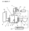
図2は本発明の実施例2のヒートポンプ式風呂給湯システムの構成図である。図2において、22は風呂ポンプであり、前記風呂回路13に備えられる。23は流量制御手段であり、第1の集熱検出手段14の信号に基き風呂ポンプ21の流量を制御する。
【0025】
以上の構成において、その動作、作用について説明する。
【0026】
大気熱と浴槽残湯熱を同時に集熱する運転において、残湯温度が高いために大気熱集熱できないことを第1の集熱検出手段14が検出して流量制御手段23へ信号を送る。そして、流量制御手段23は風呂ボンプ21の流量を低下させる制御をおこない、熱回収熱交換器6および蒸発器4を流れる冷媒温度を外気温度よりも下げて、大気熱集熱する。従って、浴槽残湯熱回収と大気熱を同時集熱する運転時間が拡大できるとともに、蒸発器および熱回収熱交換器の小型化が実現できる。
【0027】
(実施例3)
図3は本発明の実施例3のヒートポンプ式風呂給湯システムの構成図である。図3において、24は送風機であり、前記蒸発器4に大気熱を強制的に送る。25は送風機制御手段であり、第2の集熱検出手段17の信号に基き送風機24の回転数を制御する。
【0028】
以上の構成において、その動作、作用について説明する。
【0029】
大気熱と浴槽残湯熱を同時に集熱する運転において、残湯温度が低いために、浴槽残湯熱を集熱できないことを第2の集熱検出手段17が検出して流量制御手段23へ信号を送る。そして、送風機制御手段25は送風機24の回転数を下げて、熱回収熱交換器6および蒸発器4を流れる冷媒温度を下げ、浴槽残湯熱を集熱できるようにする。従って、送風機の回転数制御といった簡単な構成で大気熱利用運転時に浴槽残湯熱も集熱できるようになり、蒸発器の小型化が実現できる。
【0030】
(実施例4)
図4は本発明の実施例4のヒートポンプ式風呂給湯システムの構成図である。図4において、26は冷媒温度検出手段であり、蒸発器4の冷媒入口温度を検出する。27は低温運転制御手段であり、冷媒温度検出手段26の信号を受けて流路制御手段23を制御する。
【0031】
以上の構成において、その動作、作用について説明する。
【0032】
冬季の大気熱利用運転時において、蒸発器4に着霜が生じはじめたことを冷媒温度検出手段26が検出して、低温運転制御手段27に信号を送る。そして、低温運転制御手段27は熱回収熱交換器6に冷媒を流すように流路制御手段23を制御する。従って、蒸発器4および熱回収熱交換器6を流れる冷媒温度は上昇して、蒸発器表面の霜が融解、または着霜の進行が遅くなるため大気熱と浴槽残湯熱の集熱量は増加して、貯湯熱量が増加する。
【0033】
(実施例5)
図5は本発明の実施例5のヒートポンプ式風呂給湯システムの構成図である。図5において、28は吐出温度検出手段であり、圧縮機1の冷媒吐出温度を検出する。29は運転制御手段であり、吐出温度検出手段28の信号を受けて流路制御手段23を制御する。
【0034】
以上の構成において、その動作、作用について説明する。大気熱利用運転時あるいは浴槽残湯熱利用運転時において、圧縮機1の冷媒吐出温度が異常上昇したことを吐出温度検出手段28で検出して、運転制御手段29は蒸発器4および熱回収熱交換器6に冷媒を流し、圧縮機1の吸入圧力を上昇、吐出圧力を低下して圧縮比を小さくする。従って、冷媒吐出温度が下がり、圧縮機の耐久性は向上する。
【0035】
(実施例6)
図6は本発明の実施例6のヒートポンプ式風呂給湯システムの構成図である。図6において、30は運転指令手段であり、熱回収熱交換器6単独あるいは蒸発器4単独で冷媒の蒸発作用をおこなう運転信号を発する。31は運転制御手段であり、運転指令手段30の信号受けて、所定時間、蒸発器4および熱回収熱交換器6ともに冷媒が流れないように流路制御手段23を制御する。
【0036】
以上の構成において、その動作、作用について説明する。
【0037】
浴槽残湯熱を利用した運転において、運転開始時に圧縮機1を運転するとともに、凝縮器2から蒸発器4および熱回収熱交換器6へ冷媒が流れないように流路制御手段23を所定時間、閉状態にする。そして、蒸発器4および熱回収熱交換器6内部に溜まった冷媒を圧縮機1で回収して凝縮器2へ流出する。そして、所定時間後に、流路制御手段23を切り替えて圧縮機1、貯湯タンクの水を加熱する凝縮器2、浴槽残湯熱を集熱する熱回収熱交換器6を冷媒が循環するようにする。次に、大気熱を集熱する運転においては、蒸発器4および熱回収熱交換器6内部に溜まった冷媒を圧縮機1で回収して凝縮器2へ流出した所定時間後に、流路制御手段22を切り替えて圧縮機1、貯湯タンク8の水を加熱する凝縮器2、大気熱を集熱する蒸発器4を冷媒が循環するようにする。従って、浴槽残湯熱利用運転時および大気熱利用運転時に規定冷媒封入量でサイクル循環をおこなうため、性能および機器の信頼性が向上する。
【0038】
(実施例7)
図7は本発明の実施例7のヒートポンプ式風呂給湯システムの構成図である。図7において、32は冷媒回収温度検出手段であり、熱回収熱交換器6の冷媒入口温度を検出する。33はポンプ制御手段であり、冷媒回収温度検出手段32の信号を受けて風呂ポンプ22を最大流量に制御する。
【0039】
以上の構成において、その動作、作用について説明する。浴槽残湯熱を利用して貯湯運転をおこなう場合において、残湯熱の回収終了を冷媒回収温度検出手段32で検出して、ポンプ制御手段33へ信号を送り、ポンプ制御手段33は風呂ポンプ22を最大流量で循環させる。そして、風呂熱交換器12内を最大流速で流して、風呂熱交換器12内のスケールなどを流出する。従って、風呂熱交換器内の目詰まりを防止でき、耐久性が向上する。尚、冷媒回収温度検出手段32の代わりに風呂回路に設けた風呂温度検出手段34で浴槽残湯温度を検出して、ポンプ制御手段33へ信号を送り、風呂ポンプ22を最大流量に制御しても同様の効果を得る。
【0040】
【発明の効果】
以上の説明から明らかのように、本発明のヒートポンプ式風呂システムによれば次の効果を奏する。
【0041】
浴槽残湯熱と大気熱を同時に集熱できる場合には、同時集熱して高集熱高効率運転をおこない、同時集熱できない場合には、蒸発器と熱回収熱交換器のいづれか集熱できる熱交換器に冷媒を流すように冷媒流路を切り替えて運転をおこない、集熱量増加と機器の信頼性を向上する。
【図面の簡単な説明】
【図1】本発明の実施例1のヒートポンプ式風呂給湯システムの構成図
【図2】本発明の実施例2のヒートポンプ式風呂給湯システムの構成図
【図3】本発明の実施例3のヒートポンプ式風呂給湯システムの構成図
【図4】本発明の実施例4のヒートポンプ式風呂給湯システムの構成図
【図5】本発明の実施例5のヒートポンプ式風呂給湯システムの構成図
【図6】本発明の実施例6のヒートポンプ式風呂給湯システムの構成図
【図7】本発明の実施例7のヒートポンプ式風呂給湯システムの構成図
【図8】従来のヒートポンプシステムの構成図
【符号の説明】
1 圧縮機
2 凝縮器
3 第1の減圧手段
4 蒸発器
5 第2の減圧手段
6 熱回収熱交換器
7 流路制御手段
8 貯湯タンク
9 給湯熱交換器
10 給湯回路
11 浴槽
12 風呂熱交換器
13 風呂回路
14 第1の集熱検出手段
15 蒸発器温度検出手段
16 外気温度検出手段
17 第2の集熱検出手段
18 熱回収冷媒温度検出手段
19 風呂温度検出手段
20 運転制御手段
21 逆止弁
22 風呂ポンプ
23 流量制御手段
24 送風機
25 送風機制御手段
26 冷媒温度検出手段
27 低温運転制御手段
28 吐出温度検出手段
29 運転制御手段
30 運転指令手段
31 運転制御手段
32 冷媒回収温度検出手段
33 ポンプ制御手段
34 風呂温度検出手段[0001]
BACKGROUND OF THE INVENTION
The present invention relates to a heat pump bath hot water supply system.
[0002]
[Prior art]
Conventionally, this type of heat pump is disclosed in Japanese Patent Application Laid-Open No. 7-71839. Hereinafter, conventional techniques will be described with reference to the drawings. FIG. 8 is a configuration diagram of a conventional heat pump system. In FIG. 8, in the bathtub waste heat utilization hot water supply operation, the on-off valves 50a and 50d are opened, the bathtub hot water is collected via the waste heat
[0003]
[Problems to be solved by the invention]
However, in the conventional heat pump system, when the waste heat from the bathtub is used, the refrigerant depressurized by the refrigerant flow rate adjustment valve 51 flows through the waste heat
[0004]
The present invention solves the above-described problems, and mainly aims to save energy and increase the amount of heat collected by collecting the waste heat of the bathtub and the heat of the atmosphere simultaneously or collecting the waste heat of the bathtub with high efficiency.
[0005]
[Means for Solving the Problems]
In order to solve the above problems, the present invention provides a compressor, a condenser, an evaporator for collecting atmospheric heat or solar heat, a heat recovery heat exchanger provided in parallel with the evaporator, the evaporator and the heat. A flow path control means for controlling the flow of refrigerant to the recovered heat exchanger, a hot water storage tank, a hot water supply circuit having a hot water heat exchanger having a heat exchange relationship with the condenser, and a heat exchange relationship with the heat recovery heat exchanger. A bath circuit having a bath heat exchanger, first heat collection detecting means for detecting heat collection in the evaporator, and second heat collection detection means for detecting heat collection in the heat recovery heat exchanger. And a heat pump type hot water supply system having operation control means for controlling the flow path control means, wherein the operation control means outputs signals from the first heat collection detection means and the second heat collection detection means. receiving and controlling the flow path switching means, the operating system The means controls the flow path switching means to switch the flow path so that the refrigerant flows through either the evaporator or the heat recovery exchanger or simultaneously through the evaporator and the heat recovery exchanger. It is a bath hot water system.
[0006]
With the above configuration, when the refrigerant flows to the evaporator and the heat recovery heat exchanger, the atmospheric heat collection of the evaporator is detected by the first heat collection detection means, and the bath remaining hot water collection of the heat recovery heat exchanger is Detecting by the heat collecting detection means 2, the hot water from the bathtub and the atmospheric heat are collected simultaneously. In addition, when heat collection operation is performed when the bath remaining hot water temperature is high, such as immediately after completion of bathing at a low outdoor temperature in winter, atmospheric heat may not be collected by the evaporator. At that time, it is detected that the heat is not collected from the atmosphere, and the heat collecting heat exchanger alone performs the heat collecting operation without flowing the refrigerant to the evaporator. In addition, when the outdoor temperature is high, such as in summer, the remaining hot water temperature of the bathtub may decrease below the ambient temperature as the heat collection operation time elapses, and the refrigerant flowing through the heat recovery heat exchanger may become higher than the residual hot water temperature of the bathtub. is there. At that time, the heat recovery heat exchanger detects that the remaining hot water in the bathtub is not collected, and collects atmospheric heat in the evaporator without flowing the refrigerant to the heat recovery heat exchanger. Therefore, if the heat from the bath residual heat and the atmospheric heat can be collected at the same time, simultaneous heat collection is performed for high heat collection and high efficiency operation. If simultaneous heat collection is not possible, either the evaporator or the heat recovery heat exchanger is collected. Operation is performed by switching the refrigerant flow path so that the refrigerant flows through the heat exchanger that can be heated, thereby increasing the amount of heat collection and improving the reliability of the equipment.
[0007]
DETAILED DESCRIPTION OF THE INVENTION
The present invention can be carried out in the forms described in the claims to achieve the above object.
[0008]
The invention according to
[0009]
The invention according to
[0010]
According to this embodiment, when the refrigerant flows to the evaporator and the heat recovery heat exchanger, the atmospheric heat collection of the evaporator is detected by the first heat collection detection means, and the heat recovery heat exchanger is detected. When the second heat collection detection means detects the remaining heat from the bathtub and collects both the evaporator and the heat recovery heat exchanger, it collects the remaining heat from the bathtub and the atmospheric heat at the same time. To do. In addition, when heat collection operation is performed when the bath remaining hot water temperature is high, such as immediately after completion of bathing at a low outdoor temperature in winter, high-temperature refrigerant flows in the heat recovery heat exchanger and the evaporator. May not. At that time, it is detected that the heat is not collected from the atmosphere, and the heat collecting heat exchanger alone performs the heat collecting operation without flowing the refrigerant to the evaporator. In addition, when the outdoor temperature is high, such as in summer, the remaining hot water temperature of the bathtub may decrease below the ambient temperature as the heat collection operation time elapses, and the refrigerant flowing through the heat recovery heat exchanger may become higher than the residual hot water temperature of the bathtub. is there. At that time, the heat recovery heat exchanger detects that the remaining hot water in the bathtub is not collected, and collects atmospheric heat in the evaporator without flowing the refrigerant to the heat recovery heat exchanger. Therefore, if the heat from the bath residual heat and the atmospheric heat can be collected at the same time, simultaneous heat collection is performed for high heat collection and high efficiency operation. If simultaneous heat collection is not possible, either the evaporator or the heat recovery heat exchanger is collected. Operation is performed by switching the refrigerant flow path so that the refrigerant flows through the heat exchanger that can be heated, thereby increasing the amount of heat collection and improving the reliability of the equipment.
[0011]
In addition to the configuration of
[0012]
In addition to the structure of
[0013]
According to a fifth aspect of the invention, in addition to the configuration of the first aspect , the refrigerant temperature detecting means for detecting the refrigerant inlet temperature of the evaporator, and the flow path control means are controlled by receiving a signal from the refrigerant temperature detecting means. It is equipped with a low-temperature operation control means, and detects that frosting has started to occur in the evaporator during the winter atmospheric heat operation, and also flows the refrigerant through the heat recovery heat exchanger. The temperature of the refrigerant flowing through the evaporator and the heat recovery heat exchanger is raised to melt the frost on the evaporator surface or slow the progress of frost formation. To increase.
[0014]
According to a sixth aspect of the invention, in addition to the configuration of the first aspect , the discharge temperature detecting means for detecting the refrigerant discharge temperature of the compressor, and the flow path control means are controlled by receiving a signal from the discharge temperature detecting means. It is provided with an operation control means, and detects that the refrigerant discharge temperature of the compressor has abnormally increased during the operation using atmospheric heat or the operation using residual hot water from the bathtub, and flows the refrigerant through the evaporator and the heat recovery heat exchanger, Since the compressor suction pressure is increased and the discharge pressure is decreased to reduce the compression ratio and the refrigerant discharge temperature is lowered, the durability of the compressor is improved.
[0015]
In addition to the structure of
[0016]
According to an eighth aspect of the present invention, in addition to the configuration of the first aspect , a refrigerant recovery temperature detecting means for detecting a refrigerant inlet temperature of a heat recovery heat exchanger, and a signal received from the refrigerant recovery temperature detection means in response to the bath. A pump control means is provided to control the pump to the maximum flow rate, and when the hot water storage operation is performed using the remaining hot water from the bathtub, the end of the recovery of the remaining hot water is detected and the maximum flow rate of the bath pump in the bath heat exchanger is detected. It is circulated in and the scale in the bath heat exchanger flows out. Therefore, since the clogging in the bath heat exchanger can be prevented, durability is improved.
[0017]
【Example】
Embodiments of the present invention will be described below with reference to the drawings. In addition, in a prior art example and each Example, the same code | symbol is attached | subjected about what has the same structure and the same operation | movement, and description is partially abbreviate | omitted.
[0018]
(Example 1)
FIG. 1 is a configuration diagram of a heat pump bath hot water supply system according to
[0019]
[0020]
The operation and action of the above configuration will be described.
[0021]
In the operation that collects bath waste heat and atmospheric heat at the same time, this section describes the operation when the bath residual hot water temperature is high, such as immediately after bathing at low outdoor temperature in winter. The refrigerant discharged from the
[0022]
If a
[0023]
If the
[0024]
(Example 2)
FIG. 2 is a configuration diagram of a heat pump bath hot water supply system according to
[0025]
The operation and action of the above configuration will be described.
[0026]
In the operation of collecting the atmospheric heat and the remaining hot water from the bathtub at the same time, the first heat
[0027]
(Example 3)
FIG. 3 is a configuration diagram of a heat pump bath hot water supply system according to
[0028]
The operation and action of the above configuration will be described.
[0029]
In the operation of collecting the atmospheric heat and the bath residual hot water simultaneously, the second heat
[0030]
(Example 4)
FIG. 4 is a configuration diagram of a heat pump bath hot water supply system according to
[0031]
The operation and action of the above configuration will be described.
[0032]
The refrigerant temperature detection means 26 detects that frosting has started to occur in the
[0033]
(Example 5)
FIG. 5 is a configuration diagram of a heat pump bath hot water supply system according to
[0034]
The operation and action of the above configuration will be described. During the operation using the atmospheric heat or the operation using the remaining hot water from the bathtub, the discharge temperature detection means 28 detects that the refrigerant discharge temperature of the
[0035]
(Example 6)
FIG. 6 is a configuration diagram of a heat pump bath water heating system according to a sixth embodiment of the present invention. In FIG. 6,
[0036]
The operation and action of the above configuration will be described.
[0037]
In the operation using the remaining hot water from the bathtub, the
[0038]
(Example 7)
FIG. 7 is a block diagram of a heat pump bath water heating system according to a seventh embodiment of the present invention. In FIG. 7,
[0039]
The operation and action of the above configuration will be described. When the hot water storage operation is performed using the remaining hot water of the bathtub, the refrigerant recovery temperature detection means 32 detects the end of the recovery of the remaining hot water and sends a signal to the pump control means 33, and the pump control means 33 is sent to the
[0040]
【The invention's effect】
As is apparent from the above description, the heat pump bath system of the present invention has the following effects.
[0041]
If the heat from the bath residual heat and atmospheric heat can be collected at the same time, high heat collection and high efficiency operation can be performed by collecting heat at the same time. If simultaneous heat collection is not possible, either the evaporator or the heat recovery heat exchanger can be collected. Operation is performed by switching the refrigerant flow path so that the refrigerant flows through the heat exchanger, thereby increasing the amount of heat collection and improving the reliability of the equipment.
[Brief description of the drawings]
FIG. 1 is a block diagram of a heat pump type hot water supply system according to a first embodiment of the present invention. FIG. 2 is a block diagram of a heat pump type hot water supply system according to a second embodiment of the present invention. Fig. 4 is a block diagram of a heat pump type bath water heating system according to a fourth embodiment of the present invention. Fig. 5 is a block diagram of a heat pump type bath water heating system according to a fifth embodiment of the present invention. FIG. 7 is a block diagram of a heat pump bath water heating system according to a sixth embodiment of the present invention. FIG. 7 is a block diagram of a heat pump bath water heating system according to a seventh embodiment of the present invention.
DESCRIPTION OF
Claims (8)
Priority Applications (1)
| Application Number | Priority Date | Filing Date | Title |
|---|---|---|---|
| JP28810997A JP3632401B2 (en) | 1997-10-21 | 1997-10-21 | Heat pump bath water supply system |
Applications Claiming Priority (1)
| Application Number | Priority Date | Filing Date | Title |
|---|---|---|---|
| JP28810997A JP3632401B2 (en) | 1997-10-21 | 1997-10-21 | Heat pump bath water supply system |
Publications (2)
| Publication Number | Publication Date |
|---|---|
| JPH11118246A JPH11118246A (en) | 1999-04-30 |
| JP3632401B2 true JP3632401B2 (en) | 2005-03-23 |
Family
ID=17725926
Family Applications (1)
| Application Number | Title | Priority Date | Filing Date |
|---|---|---|---|
| JP28810997A Expired - Fee Related JP3632401B2 (en) | 1997-10-21 | 1997-10-21 | Heat pump bath water supply system |
Country Status (1)
| Country | Link |
|---|---|
| JP (1) | JP3632401B2 (en) |
Families Citing this family (5)
| Publication number | Priority date | Publication date | Assignee | Title |
|---|---|---|---|---|
| JP2007315620A (en) | 2006-05-23 | 2007-12-06 | Sanden Corp | Water heater |
| GB2559496B (en) * | 2015-11-18 | 2020-04-29 | Mitsubishi Electric Corp | Heat pump hot water supply apparatus |
| CN107191359B (en) * | 2017-07-19 | 2019-08-30 | 启明天工(苏州)控制系统有限公司 | A kind of air compressor cooling means and system |
| CN111156697B (en) * | 2020-01-08 | 2021-08-31 | 北京建筑大学 | Heat pump water heater with waste heat recovery function |
| CN112594769B (en) * | 2020-12-24 | 2022-01-04 | 三峡大学 | Multi-energy supply device and method based on aluminum micro-channel heat pipe technology |
-
1997
- 1997-10-21 JP JP28810997A patent/JP3632401B2/en not_active Expired - Fee Related
Also Published As
| Publication number | Publication date |
|---|---|
| JPH11118246A (en) | 1999-04-30 |
Similar Documents
| Publication | Publication Date | Title |
|---|---|---|
| US5816065A (en) | Desiccant assisted air conditioning system | |
| EP2381178B1 (en) | Heat pump type heating apparatus | |
| CN101984311B (en) | Hot-water frost preventing and defrosting device with compressor cooling | |
| CN101221007B (en) | Air source heat pump hot water units | |
| JP3663828B2 (en) | Heat pump bath water supply system | |
| JP3632401B2 (en) | Heat pump bath water supply system | |
| JP3632306B2 (en) | Heat pump bath water supply system | |
| CN112611072A (en) | Control method of cooling and heating air conditioner | |
| JP2003035454A (en) | Heat pump hot water supply apparatus | |
| JP3840914B2 (en) | Heat pump bath water supply system | |
| JP3800721B2 (en) | Heat pump type water heater | |
| JPS6310349B2 (en) | ||
| JP3703995B2 (en) | Heat pump water heater | |
| JP3996321B2 (en) | Air conditioner and its control method | |
| CN201003885Y (en) | Air source thermal pump water heater unit | |
| JPS5986846A (en) | Hot water supply device of heat pump type | |
| JP2004347272A (en) | Refrigerating plant | |
| JPH1019409A (en) | Air conditioner | |
| JP3457697B2 (en) | Air conditioner | |
| JP2006029637A (en) | Heat storage type air conditioner and its operation method | |
| JP3588948B2 (en) | Heat pump type bath hot water supply system | |
| CN217785325U (en) | Fresh air conditioner | |
| CN220852611U (en) | Self-cleaning heat pump water heater | |
| JPH03125856A (en) | Heat pump hot water feeder | |
| KR20130064382A (en) | Heat pump system for electric vehicle and control method thereof |
Legal Events
| Date | Code | Title | Description |
|---|---|---|---|
| A977 | Report on retrieval |
Free format text: JAPANESE INTERMEDIATE CODE: A971007 Effective date: 20040510 |
|
| A521 | Written amendment |
Free format text: JAPANESE INTERMEDIATE CODE: A523 Effective date: 20040603 |
|
| A131 | Notification of reasons for refusal |
Free format text: JAPANESE INTERMEDIATE CODE: A131 Effective date: 20040727 |
|
| A521 | Written amendment |
Free format text: JAPANESE INTERMEDIATE CODE: A523 Effective date: 20040924 |
|
| TRDD | Decision of grant or rejection written | ||
| A01 | Written decision to grant a patent or to grant a registration (utility model) |
Free format text: JAPANESE INTERMEDIATE CODE: A01 Effective date: 20041130 |
|
| A61 | First payment of annual fees (during grant procedure) |
Free format text: JAPANESE INTERMEDIATE CODE: A61 Effective date: 20041213 |
|
| FPAY | Renewal fee payment (event date is renewal date of database) |
Free format text: PAYMENT UNTIL: 20080107 Year of fee payment: 3 |
|
| FPAY | Renewal fee payment (event date is renewal date of database) |
Free format text: PAYMENT UNTIL: 20090107 Year of fee payment: 4 |
|
| FPAY | Renewal fee payment (event date is renewal date of database) |
Free format text: PAYMENT UNTIL: 20100107 Year of fee payment: 5 |
|
| FPAY | Renewal fee payment (event date is renewal date of database) |
Free format text: PAYMENT UNTIL: 20110107 Year of fee payment: 6 |
|
| FPAY | Renewal fee payment (event date is renewal date of database) |
Free format text: PAYMENT UNTIL: 20110107 Year of fee payment: 6 |
|
| FPAY | Renewal fee payment (event date is renewal date of database) |
Free format text: PAYMENT UNTIL: 20120107 Year of fee payment: 7 |
|
| FPAY | Renewal fee payment (event date is renewal date of database) |
Free format text: PAYMENT UNTIL: 20130107 Year of fee payment: 8 |
|
| FPAY | Renewal fee payment (event date is renewal date of database) |
Free format text: PAYMENT UNTIL: 20140107 Year of fee payment: 9 |
|
| LAPS | Cancellation because of no payment of annual fees |