JP3632061B2 - Dispensing device - Google Patents
Dispensing device Download PDFInfo
- Publication number
- JP3632061B2 JP3632061B2 JP17160097A JP17160097A JP3632061B2 JP 3632061 B2 JP3632061 B2 JP 3632061B2 JP 17160097 A JP17160097 A JP 17160097A JP 17160097 A JP17160097 A JP 17160097A JP 3632061 B2 JP3632061 B2 JP 3632061B2
- Authority
- JP
- Japan
- Prior art keywords
- container
- pushbutton
- push button
- gasket
- shutter
- Prior art date
- Legal status (The legal status is an assumption and is not a legal conclusion. Google has not performed a legal analysis and makes no representation as to the accuracy of the status listed.)
- Expired - Fee Related
Links
Images


Classifications
-
- B—PERFORMING OPERATIONS; TRANSPORTING
- B65—CONVEYING; PACKING; STORING; HANDLING THIN OR FILAMENTARY MATERIAL
- B65D—CONTAINERS FOR STORAGE OR TRANSPORT OF ARTICLES OR MATERIALS, e.g. BAGS, BARRELS, BOTTLES, BOXES, CANS, CARTONS, CRATES, DRUMS, JARS, TANKS, HOPPERS, FORWARDING CONTAINERS; ACCESSORIES, CLOSURES, OR FITTINGS THEREFOR; PACKAGING ELEMENTS; PACKAGES
- B65D81/00—Containers, packaging elements, or packages, for contents presenting particular transport or storage problems, or adapted to be used for non-packaging purposes after removal of contents
- B65D81/32—Containers, packaging elements, or packages, for contents presenting particular transport or storage problems, or adapted to be used for non-packaging purposes after removal of contents for packaging two or more different materials which must be maintained separate prior to use in admixture
- B65D81/3205—Separate rigid or semi-rigid containers joined to each other at their external surfaces
- B65D81/3211—Separate rigid or semi-rigid containers joined to each other at their external surfaces coaxially and provided with means facilitating admixture
-
- B—PERFORMING OPERATIONS; TRANSPORTING
- B65—CONVEYING; PACKING; STORING; HANDLING THIN OR FILAMENTARY MATERIAL
- B65D—CONTAINERS FOR STORAGE OR TRANSPORT OF ARTICLES OR MATERIALS, e.g. BAGS, BARRELS, BOTTLES, BOXES, CANS, CARTONS, CRATES, DRUMS, JARS, TANKS, HOPPERS, FORWARDING CONTAINERS; ACCESSORIES, CLOSURES, OR FITTINGS THEREFOR; PACKAGING ELEMENTS; PACKAGES
- B65D51/00—Closures not otherwise provided for
- B65D51/24—Closures not otherwise provided for combined or co-operating with auxiliary devices for non-closing purposes
- B65D51/28—Closures not otherwise provided for combined or co-operating with auxiliary devices for non-closing purposes with auxiliary containers for additional articles or materials
- B65D51/2807—Closures not otherwise provided for combined or co-operating with auxiliary devices for non-closing purposes with auxiliary containers for additional articles or materials the closure presenting means for placing the additional articles or materials in contact with the main contents by acting on a part of the closure without removing the closure, e.g. by pushing down, pulling up, rotating or turning a part of the closure, or upon initial opening of the container
- B65D51/2814—Closures not otherwise provided for combined or co-operating with auxiliary devices for non-closing purposes with auxiliary containers for additional articles or materials the closure presenting means for placing the additional articles or materials in contact with the main contents by acting on a part of the closure without removing the closure, e.g. by pushing down, pulling up, rotating or turning a part of the closure, or upon initial opening of the container the additional article or materials being released by piercing, cutting or tearing an element enclosing it
- B65D51/2828—Closures not otherwise provided for combined or co-operating with auxiliary devices for non-closing purposes with auxiliary containers for additional articles or materials the closure presenting means for placing the additional articles or materials in contact with the main contents by acting on a part of the closure without removing the closure, e.g. by pushing down, pulling up, rotating or turning a part of the closure, or upon initial opening of the container the additional article or materials being released by piercing, cutting or tearing an element enclosing it said element being a film or a foil
- B65D51/2835—Closures not otherwise provided for combined or co-operating with auxiliary devices for non-closing purposes with auxiliary containers for additional articles or materials the closure presenting means for placing the additional articles or materials in contact with the main contents by acting on a part of the closure without removing the closure, e.g. by pushing down, pulling up, rotating or turning a part of the closure, or upon initial opening of the container the additional article or materials being released by piercing, cutting or tearing an element enclosing it said element being a film or a foil ruptured by a sharp element, e.g. a cutter or a piercer
-
- B—PERFORMING OPERATIONS; TRANSPORTING
- B65—CONVEYING; PACKING; STORING; HANDLING THIN OR FILAMENTARY MATERIAL
- B65D—CONTAINERS FOR STORAGE OR TRANSPORT OF ARTICLES OR MATERIALS, e.g. BAGS, BARRELS, BOTTLES, BOXES, CANS, CARTONS, CRATES, DRUMS, JARS, TANKS, HOPPERS, FORWARDING CONTAINERS; ACCESSORIES, CLOSURES, OR FITTINGS THEREFOR; PACKAGING ELEMENTS; PACKAGES
- B65D51/00—Closures not otherwise provided for
- B65D51/24—Closures not otherwise provided for combined or co-operating with auxiliary devices for non-closing purposes
- B65D51/28—Closures not otherwise provided for combined or co-operating with auxiliary devices for non-closing purposes with auxiliary containers for additional articles or materials
- B65D51/2807—Closures not otherwise provided for combined or co-operating with auxiliary devices for non-closing purposes with auxiliary containers for additional articles or materials the closure presenting means for placing the additional articles or materials in contact with the main contents by acting on a part of the closure without removing the closure, e.g. by pushing down, pulling up, rotating or turning a part of the closure, or upon initial opening of the container
- B65D51/2857—Closures not otherwise provided for combined or co-operating with auxiliary devices for non-closing purposes with auxiliary containers for additional articles or materials the closure presenting means for placing the additional articles or materials in contact with the main contents by acting on a part of the closure without removing the closure, e.g. by pushing down, pulling up, rotating or turning a part of the closure, or upon initial opening of the container the additional article or materials being released by displacing or removing an element enclosing it
- B65D51/2864—Closures not otherwise provided for combined or co-operating with auxiliary devices for non-closing purposes with auxiliary containers for additional articles or materials the closure presenting means for placing the additional articles or materials in contact with the main contents by acting on a part of the closure without removing the closure, e.g. by pushing down, pulling up, rotating or turning a part of the closure, or upon initial opening of the container the additional article or materials being released by displacing or removing an element enclosing it the element being a plug or like element closing a passage between the auxiliary container and the main container
- B65D51/2871—Closures not otherwise provided for combined or co-operating with auxiliary devices for non-closing purposes with auxiliary containers for additional articles or materials the closure presenting means for placing the additional articles or materials in contact with the main contents by acting on a part of the closure without removing the closure, e.g. by pushing down, pulling up, rotating or turning a part of the closure, or upon initial opening of the container the additional article or materials being released by displacing or removing an element enclosing it the element being a plug or like element closing a passage between the auxiliary container and the main container the plug falling into the main container
-
- B—PERFORMING OPERATIONS; TRANSPORTING
- B65—CONVEYING; PACKING; STORING; HANDLING THIN OR FILAMENTARY MATERIAL
- B65D—CONTAINERS FOR STORAGE OR TRANSPORT OF ARTICLES OR MATERIALS, e.g. BAGS, BARRELS, BOTTLES, BOXES, CANS, CARTONS, CRATES, DRUMS, JARS, TANKS, HOPPERS, FORWARDING CONTAINERS; ACCESSORIES, CLOSURES, OR FITTINGS THEREFOR; PACKAGING ELEMENTS; PACKAGES
- B65D51/00—Closures not otherwise provided for
- B65D51/24—Closures not otherwise provided for combined or co-operating with auxiliary devices for non-closing purposes
- B65D51/28—Closures not otherwise provided for combined or co-operating with auxiliary devices for non-closing purposes with auxiliary containers for additional articles or materials
- B65D51/2807—Closures not otherwise provided for combined or co-operating with auxiliary devices for non-closing purposes with auxiliary containers for additional articles or materials the closure presenting means for placing the additional articles or materials in contact with the main contents by acting on a part of the closure without removing the closure, e.g. by pushing down, pulling up, rotating or turning a part of the closure, or upon initial opening of the container
- B65D51/2857—Closures not otherwise provided for combined or co-operating with auxiliary devices for non-closing purposes with auxiliary containers for additional articles or materials the closure presenting means for placing the additional articles or materials in contact with the main contents by acting on a part of the closure without removing the closure, e.g. by pushing down, pulling up, rotating or turning a part of the closure, or upon initial opening of the container the additional article or materials being released by displacing or removing an element enclosing it
- B65D51/2878—Closures not otherwise provided for combined or co-operating with auxiliary devices for non-closing purposes with auxiliary containers for additional articles or materials the closure presenting means for placing the additional articles or materials in contact with the main contents by acting on a part of the closure without removing the closure, e.g. by pushing down, pulling up, rotating or turning a part of the closure, or upon initial opening of the container the additional article or materials being released by displacing or removing an element enclosing it the element being a lid or cover seated on a passage between the auxiliary container and the main container
Landscapes
- Engineering & Computer Science (AREA)
- Mechanical Engineering (AREA)
- Closures For Containers (AREA)
- Package Specialized In Special Use (AREA)
- Containers Having Bodies Formed In One Piece (AREA)
- Automatic Assembly (AREA)
- Processing And Handling Of Plastics And Other Materials For Molding In General (AREA)
Description
【0001】
【発明の属する技術分野】
この発明は少なくとも2種の物質を別々に貯蔵し、これらを混合し、得られた混合物を計量分配する装置に関する。
【0002】
【従来の技術】
仏国特許出願第2290366号明細書には2種の物質を別々に貯蔵し、これらを混合し、得られた混合物を計量分配するための装置であって、一方の物質を保有するネック付容器および他方の物質を保有するポリビニルクロリドのような半硬質プラスチック材料製で該容器のネック部に配設された有孔プレートを具備する装置が開示されている。
有孔プレートを覆うタブをはぎ取って保有された物質を容器内に落下させて容器内の他方の物質と混合させる押ボタンが該装置には配設されている。
【0003】
本件出願人による仏国特許第2722765号明細書には、最初に使用する前は2種の物質を別々に保有する2つのチャンバーを有する容器および該チャンバーを分離する可動性シャッターを具有する装置が開示されている。この装置を最初に使用するに際しては、押ボタンを用いてシャッターを移動させるかまたは引裂くことによって該チャンバーを連絡させて両方の物質を混合させる。押ボタンを押し下げるたびに、容器内の圧力が増大して所定量の混合物が放出される。使用後は戻しばねの作用によって押ボタンは最初の状態に復帰する。一般的には、2種の物質のうちの少なくとも一方は液体であるので、押ボタンは容器に対して漏洩がないように封止状態で移動させることが必要である。封止は押ボタンを容器の円筒状部分に正確に嵌合させることによって得られるが、所望により、該円筒状部分を包囲する封止スカートを配設することによって封止効果を高めてもよい。悪戯防止リングが容器上に存在する限り押ボタンの移動は防止される。この種の装置は構成部材の数がかなり多いので、その製造組立てコストは高くなる。
【0004】
【発明が解決しようとする課題】
この発明はこの種のタイプの装置を改良して、特にその製造コストの低減化を計るためになされたものである。
【0005】
【課題を解決するための手段】
この課題は少なくとも2種の物質を別々に貯蔵し、これらを混合し、得られた混合物を計量分配するための装置であって、容器、2種の物質を別々に保有する容器内の2つのチャンバーを該装置の最初の使用前に隔離する少なくとも1つのシャッター、および最初の使用に際して、該シャッターを移動させるかまたは引裂くことによって2つのチャンバーを相互に連絡させる押ボタンを具備する新規な装置によって解決された。
【0006】
即ち本発明は、少なくとも2種の物質を別々に貯蔵し、これらを混合し、得られた混合物を計量分配するための装置であって、容器、該装置を最初に使用する前に容器内において該物質を別々に保有する2つのチャンバーを隔離するのに適した少なくとも1つの可動性シャッター、および最初の使用に際して該シャッターを移動させるかまたは引裂いて2つのチャンバーを相互に連絡させるための押ボタンを具備する装置において、該容器に固定された壁部および弾性変形可能な材料製の変形可能壁部を有するガスケットであって、押ボタンを押し下げたときにこれと連動して変形すると共に容器の内部と押ボタンとの間の封止バリヤーとしての機能を持続するガスケットをさらに具有することを特徴とする計量分配装置に関する。
【0007】
【発明の実施の形態】
貯蔵中や使用中の封止を得るためには押ボタンと容器を正確に嵌合させる必要がないので本発明による装置の製造組立ては簡単化される。押ボタンと容器は多様な形態にすることができる。
【0008】
弾性変形可能材料製ガスケットの変形可能壁部は、ユーザーが押ボタンを解放するたびにこれを元に戻すばねのような作用をする。
押ボタンは押し下げられるたびに容器内の圧力を高めて予め決められた量の混合物を排出させる。
【0009】
押ボタンは最初の使用に際して破断可能な材質の少なくとも1つのブリッジによって容器に接続するのが好ましい。押ボタンは容器の一部と一体成形されるので装置の製造は簡単になる。最初の使用に際して破断されるブリッジは、悪戯防止インジケーターとしても機能する。このブリッジにより、従来の装置における容器に配設される悪戯防止リングは不要となる。
【0010】
押ボタンの形態は、最初の使用に際して前記の変形可能壁部をシャッターに衝突させるためのとがった領域を形成するように変形させるような形態にするのが好ましい。
【0011】
ガスケットを熱可塑性エラストマーから製造することによって装置のリサイクルを容易にするのが好ましい。ガスケットは特別な形態、例えば、その壁部を局部的に薄くした形態に設計することによって変形可能にしてもよい。この変形態様として、ガスケットの変形可能壁部をふいご状にしてもよい。
【0012】
ガスケットの変形可能壁部は一般にグローブフィンガー(glove finger)状にするが、その横断寸法は該変形可能壁部の少なくとも一部が押ボタンの移動中に容器の壁部との接触を実質的に維持するように選択する。好ましくは、一方の物質は容器の煙突状部材中に収納し、押ボタンは、該煙突状部材内に収納される物質層の最大の高さに等しいかまたは該高さよりも長い押し下げストロークにわたって移動できるように容器に装着させ、また、該変形可能壁部の一方の端部は該煙突状部材の壁部に対して摺動する。このような形態にすることによって、押ボタンの最初の押し下げに際して一方のチャンバー内の物質の実質上全てを他方のチャンバー内へ流入させることができる。また、これによって、ガスケットと接触する物質が粉体であって、容器内の他方の物質が液体の場合、2つのチャンバーが相互に連絡しても、チャンバーの隅や角に粉末の塊りが残存することは回避される。
【0013】
変形可能壁部の自由端には、シャッター内での1個または複数個の引裂き起点の形成または容器に対するガスケットの移動を促進するのに適した局在化スラストを加えることによるシャッターの離反の容易化を促進する部分を1個または複数個配設してもよい。
【0014】
従って、ガスケットの変形可能壁部の自由端には中央スタッドまたは連続的もしくは不連続的な周縁環状リップを配設してもよい。
【0015】
本発明の一つの態様においては、容器は中空体、該中空体に固定するための底部を含む端部部材、および該底部に固定されかつ少なくとも1つのブリッジを介して装置の最初の使用前には押ボタンに連結されたカバーを組み立てることによって形成される。該底部、該カバーおよび該押ボタンは一つの部材として一体成形するのが好ましく、底部はフィルム状ヒンジを介してカバーに連結される。このように、本発明による装置の製造組立ては従来の装置の場合に比べて著しく簡単化される。この変形態様においては、カバーと底部は別々に製造し、カバーをスナップ止めで底部に固定してもよい。また、所望の外観に応じて種々の断面形態を有するカバーと底部を製造してもよいが、この場合には、両者を組み立てた後に、ユーザーの指に対するグリップまたは迫台として作用するのに適した形態になるように両部材の形態を選択し、これによってユーザーが押ボタンを押し下げたときに装置が滑り落ちないようにする。
【0016】
シャッターは底部に溶封されたアルミニウムフィルムによって形成してもよい。この変形態様として、シャッターは容器と一体成形してもよく、また、容器内に配設される別のプラグによって形成してもよい。
【0017】
押ボタンのガスケットと接触する部分は種々の形態を有していてもよい。本発明の特定の態様においては、該部分は一組の舌状体の形態にしてもよく、これによってガスケットの中心に収束する円錐体が形成され、該円錐体はその自由端を介してガスケットの実質的な中央部をわずかに押圧することによってシャッターの中央にスラストを加える。
【0018】
悪戯防止インジケーターとして作用するブリッジが破断した後で押ボタンを保持する手段を容器に設けてもよい。接着、溶封、摩擦またはスナップ止めによってガスケットを押ボタンに固定することができる。容器および/または押ボタンには、押ボタンを最初に押して下げた後で押ボタンを保持する舌状体または爪状体を配設してもよい。
【0019】
本発明は少なくとも2種の物質を別々に貯蔵し、これらを混合し、得られた混合物を計量分配する装置の製法であって、以下の工程(i)〜(viii)を含むことを特徴とする該装置の製法にも関する:
(i)一方の端部に可動性閉鎖部材を有し、他端が開口した中空体を製造し、
(ii)煙突状部材およびフィルム状ヒンジによって相互に連結された底部とカバーを具有し、該カバーが少なくとも1つの破断性材料製ブリッジを介してカバーの残余部と連結された押ボタンを有する端部部材を一体成形させ、
(iii)煙突状部材の一方の端部に可動性シャッターを固定させるかまたは形成させ、
(iv)煙突状部材に第一物質を充填し、
(v)煙突状部材にガスケットを装着させて該部材を閉鎖させ、
(vi)フィルム状ヒンジの回転軸のまわりを旋回させることによってカバーを底部に装着させ、
(vii)中空体の開口端を介して第二物質を該中空体に充填し、
(viii)端部部材を中空体の開口端に嵌合させる。
【0020】
図1は本発明による装置の一態様を示す側面図である。
図2は図1に示す装置の模式的縦断面図である。
図3は図2において、押ボタンを容器に連結する破断性材料製ブリッジが破断した後の押ボタン部分の拡大断面図である。
図4は本発明による装置の組み立て方法を示す模式的断面図である。
図5は本発明による装置の別態様を示す部分的縦断面図である。
図6は本発明による装置のさらに別の態様を示す部分的縦断面図である。
【0021】
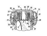
図1および図2は本発明による装置(1)の第一の態様を示すもので、該装置は容器(2)および該容器の内部を2つのチャンバー(4、5)に分割するシャッター(3)を具有する。
この態様においては、容器の底部に位置するチャンバー(4)は液状物質(L)を保有し、容器の上部に位置するチャンバー(5)は粉状物質(P)を保有する。チャンバー(4)の体積はチャンバー(5)の体積に比べてかなり大きい。もちろん、2種の液体を別々に収容する装置を用いる態様も本発明の範囲内に包含される。
【0022】
容器(2)は端部部材(7)および図示する縦軸(X)に沿って延びた管状体である中空体(6)を組み立てることによって形成される。中空体(6)はその底部端に混合物を計量分配するためのオリフィス(9)を制限するネック(8)を有する。装置の不使用時には、オリフィス(9)はいずれかの既知の固定手段によってネック(8)に固定されていてもよい可動性閉鎖キャップ(10)によって閉鎖される。
【0023】
図示する態様の場合、キャップ(10)はネック(8)の底部に近接して配設された環状リムと嵌合する形態を有する管状内側スカート(11)およびオリフィス(9)を閉鎖する形態を有する中央スタッド(13)を有する。この変形態様においては、キャップ(10)とネック(8)は共働して螺旋嵌合する形態を有していてもよく、また、本発明の範囲を逸脱することなく計量分配用オリフィス(9)を閉鎖するためにはいずれかの別の手段を用いてもよい。
【0024】
端部部材(7)は中空体(6)の開口上部端とスナップ止めされる形態を有する底部(14)およびカバー(15)を有する。図示する態様の場合、カバー(15)はフィルム状ヒンジを形成するブリッジ(16)を介して底部(14)に連結され、また、図4に示すように、180°旋回した後、該底部にスナップ止めによって固定される。
【0025】
底部(14)は端部部材(7)が図2に示すような状態にあるときに中空体(6)の上部端を包囲する円筒状の内側スカート(18)を介して底部端において上方へ延びた外部シェル(17)を有する。内側スカート(18)はブリッジ(19)を介して中央部材(20)に連結され、該中央部材はその底部において下方に開口した環状溝(21)を制限しかつ中空体(6)の上部端と嵌合する形態を有するリング(34)を具有する。中央部材(20)の上部には縦軸(X)上に中心を有する煙突状部材(22)が配設される。この煙突状部材は一般に円筒状であり、その底部端および上部端はそれぞれシャッター(3)およびガスケット(23)によって閉鎖される。
【0026】
図示する特定の態様の場合、シャッターは煙突状部材の底部オリフィスを包囲する環状表面(24)に溶封されたアルミニウムフィルムによって形成される。
【0027】
ガスケット(23)は弾性変形可能な材料製であって、煙突状部材(22)内で嵌合する中央の変形可能壁部(25)を形成し、その輪郭は煙突状部材の断面輪郭と適合する。図示する特定の態様の場合、変形可能壁部(25)は環状であって、その外径は煙突状部材(22)の内径に実質上対応する。変形可能壁部(25)はその周縁部において変形可能壁部(26)を介して上方へ延びており、変形可能壁部(26)は煙突状部材(22)の上部端を封止状態で閉鎖する下方に開口した環状溝を形成する。変形可能壁部(26)は環状の壁部(27)を介して変形可能壁部(25)に連結された端部から離れた端部において半径方向に外側へ延び、該環状の壁部(27)は縦軸(X)に対して実質上垂直に延びる。変形可能壁部(25)および煙突状部材(22)の内部に位置する変形可能壁部(26)の一部はグローブフィンガーを形成する。
【0028】
カバー(15)はシェル(29)を有しており、該シェルはスナップ止めされた後で外側に凸状の環状隆起部を形成する底部(14)のシェル(17)と共働する(図1および図2参照)。シェル(17)および(29)の外部表面は装置(1)に特定の外観を付与するような形態の部分を有していてもよく、また、該部分は所望により装置(1)を使用時に把持するのに生物工学的に好適な形態にしてもよい。図4において、(41)および(42)はそれぞれシェル(17)および(29)内に形成された環状溝を示し、これらの環状溝はスナップ止めによって相互に固定される。
【0029】
シェル(29)はその半径方向の最も内側の端部において円筒状内側スカート(30)を介して延びており、該スカートは、図2に示すように、カバー(15)が底部(14)に固定されたときにガスケット(23)の壁部(27)と接触する。
装置を最初の使用に供するまでは、内側スカート(30)は破断性材料製ブリッジを介して押ボタン(32)に連結される。
【0030】
以下に説明するように、押ボタン(32)の内部にはスラストを伝達するためのストック(33)が配設される。ストック(33)の一方の端部は壁部(35)に連結され、該壁部(35)は縦軸(X)に対して実質上垂直であって、押ボタンの上部を形成し、その周縁部においてはストック(33)の一部を包囲する外側スカート(36)に接続される。ブリッジ(31)は外側スカート(36)と内側スカート(30)を連結する。ブリッジ(31)の位置および押ボタン(32)の形態は、押ボタン(32)がシェル(29)の外側まで延びるがその作動前はブリッジ(31)によって保持されるように選択される(図1および図2参照)。
【0031】
図示する態様の場合、底部(14)、カバー(15)および押ボタン(32)は図4に示すような形態で単一部材として射出成形される。フィルム(3)を部材(20)に溶封した後、煙突状部材(22)に物質(P)を充填し、ガスケット(23)を装着させる。
次いで、カバー(15)を180°旋回させて底部(14)にスナップ止めする。ガスケット(23)の壁部(27)をリング(34)の上部面と内側スカート(30)の自由端の間に締結させる(図2参照)。リング(34)はガスケット(23)に面した表面上に環状リブ(28)を有していてもよく、これによって部材(20)とカバー(15)の間の封止状態を改良することができる。物質(P)保有するチャンバー(5)は周囲の空気からはガスケット(23)によって隔離されており、これによって装置を最初に使用するまでの物質(P)の良好な保存が保証される。
【0032】
ブリッジ(31)が破断された後で押ボタン(32)を端部部材(7)上に保持する手段を設けるのが好ましい。
ストック(33)は接着、溶封、摩擦またはスナップ止めによってガスケット(23)の中央の変形可能壁部(25)に連結することができる。以下に説明するように、カバーと共に共働する保持手段を押ボタン上に設けてもよい。
物質(L)が充填された後、端部部材(7)は中空体(6)上にスナップ止めされる。ネック(8)には予め閉鎖キャップ(10)が装着される。
【0033】
図示する態様の場合、環状リム(37)は中空体(6)の上部端に隣接して形成され、また、底部(14)は、端部部材(7)が中空体(6)に固定されたときに端部部材(7)を中空体(6)に保持する形態を有する内部突起(38)を有する。
中空体(6)の上部の端部面を溝(21)の底部へ押圧することによって容器は封止状に閉鎖される。端部部材(7)を中空体(6)に固定する方法としては本発明の範囲を逸脱することなく種々の方法を採用することができる。
【0034】
中空体(6)には物質(L)を完全に充填しないのが好ましく、これによって残存するガス相がシャッター(3)が離反または引裂かれた後での2種の物質の混合を促進することができる。
装置の最初の使用に際しては、ユーザーは押ボタンに圧力を加えることによって押ボタンを内側スカート(30)に固定するブリッジを破断することができる。押ボタン(32)の押し下げによってガスケット(23)に圧力が印加され、ガスケットは、図示する態様の場合にはチャンバー(5)に収容された物質(P)に圧力を伝達するのでフィルム(3)が引裂かれて物質(P)が中空体(6)の内部へ放出されるので物質(P)は物質(L)と混合される。
【0035】
図示する態様の場合、変形可能壁部(25)はその周縁部および物質(P)と接触する面上に突起部(40)を有しており、該突起部はシャッター(3)内に引裂き起点を形成する。
チャンバー(4)と(5)を相互に連絡させる押ボタンの壁部(35)に加えられる力は低減されるので、シャッター(3)は予め決められた様式に従って除去されるかまたは引裂かれる。
【0036】
ストック(33)はブリッジ(31)が破断されない限りシャッター(3)に有意なスラストを及ぼさない。装置(1)の最初の使用に際しては、ブリッジの破断は急激におこなわれるので、ストック(33)はストライカーの作用をし、これによって物質(P)の全てまたはほとんど全ては装置の方向にかかわらずに物質(L)の内部の深くまで放出される。これによって物質(P)は物質(L)内において迅速かつ効果的に混合される。
【0037】
押ボタンの降下中は、ガスケット(23)が変形し、ストック(33)はチャンバー(5)の上部端を封止状態で閉鎖しながら移動する(図3参照)。即ち、図示する態様の場合、煙突状部材(22)の内部に位置する変形可能壁部(26)は弾性的に引っ張られ、一方、押ボタン(32)はその材質の弾性のために押し下げられ、この変形可能壁部(26)は最初の高さの10%またはそれ以上伸長する。ユーザーが押ボタンを解放すると、ガスケット(23)の弾性的に変形した部分は最初の状態に復帰するので押ボタンは元の位置に戻る。下方へのストロークの最後においては、外側スカート(36)はガスケット(23)の壁部(27)と接触する。これによって硬質プラスチック材料製部材間の衝突が回避されるので、装置(1)の使い易さが改良されると共に装置の損傷の危険が回避される。
【0038】
押ボタンは容器に対して予め決められたストロークにわたって押し下げられるたびに容器の内部にわずかの余圧を発生させるので、予め決められた量の混合物がオリフィス(9)を通して放出される。
【0039】
図5は本発明による第2の態様の装置(1’)を示す。この装置は先の態様の場合と同じ部材に具有し、これらの部材は同じ番号で示し、再び説明しない。
装置(1’)は装置(1)とは異なり、シャッターは溶封フィルム状の形態ではなく、底部(14)と一体成形された薄い壁部(3’)から形成される。図5に示すように、壁部(3’)はその周縁部において肉薄リング(41)と連結させるのが好ましく、これによって部材(20)からの壁部(3’)の離脱が容易となる。
【0040】
ガスケットは本発明の範囲を逸脱することなく種々の形態にすることができ、図5に示すガスケット(23’)は次の点で前述のガスケット(23)とは相違する。即ち、変形可能壁部(25)は内部面に環状凹部を有する変形可能壁部(26’)を介してガスケット(23’)の残余部に連結され、これによって押ボタンの下方への移動に伴うガスケットの変形が容易となる。また、押ボタンを押し下げたときに予め決められた様式で変形するような形態のガスケットを用いることもできる。
【0041】
この態様における押ボタン(32’)はガスケット(23’)の変形可能壁部(25)の狭い領域にスラストを及ぼすような形態を有する。即ち、押ボタンは最初の使用に際してガスケットの変形可能壁部をシャッターを撃破するためのとがった領域が形成されるような形態にする。従ってこの態様の場合には、先の態様の場合のストック(33)は、変形可能壁部(25)の中心に収束する円錐状に配設された一組のフィン(43)によって置き換えられる。ユーザーが押ボタン(32’)を押すと、押ボタンはその下降の開始において変形可能壁部(25)の中央部のみを押圧するので、物質(P)を介してシャッター(3’)の中央部に高い圧力が印加され、シャッターの離反または引裂きが容易となる。スラストが主としてシャッターの中央部に加わるので、押ボタンの最初の押し下げに際して物質(P)の全体的な押圧は回避される。
【0042】
図6は本発明の第三の態様による装置(1”)を示す。装置(1”)はシャッターが煙突状部材(22)の底部開口部に嵌合したブラグ(3”)によって形成される点で前述の装置とは相違する。さらに、ガスケット(23”)はその変形可能壁部(25)の中央部および物質(P)と接触する面上にスタッド(44)を有しており、該スタッドの先端部はシャッター(3”)を押圧する。押ボタン(32)を押し下げると、スラストは物質(P)の層を通ることなくスタッド(44)を介してシャッター(3”)に直接伝達され、これによって押ボタンを最初に押し下げる際の物質(P)の押圧は回避される。
【0043】
押ボタン(32)はガスケットに固定することによる別の方式によって保持することも可能である。例えば、図6には押ボタン(32)の外側スカート(36)の周縁部に形成された爪状体(45)を示す。該爪状体は押ボタンを最初に押し下げたときに弾性的に曲がるので、押ボタンは外側スカート(36)の内部面に形成された掛け金状突起(46)を越えて移動する。これらの突起(46)は装置の最初の使用後は押ボタン(32)をカバー(15)上に保持するような形態を有する。
【0044】
前述の3種の態様においては、変形可能壁部(25)は煙突状部材(22)の半径方向の内部面との接触を実質的に維持し、また、押ボタンはチャンバー(5)内に収納された物質層の最大高さと等しいかまたは該高さよりも長いストロークにわたって移動するので、チャンバー(5)内に収納された物質は、装置を把持する状態にかかわらず、押ボタンの最初の押し下げによって実質上全て放出される。
【0045】
本発明は前述の態様に限定されるものではない。特に、中空体(6)の形態と端部部材(7)の形態は、フィルム状ヒンジによって連結された2つの部材(14)と(15)を用いることによって多様な形態の端部部材(7)を製造することができるので、多種多様に改変することが可能である。
また、本発明の範囲を逸脱することなく、容器内に複数の可動性シャッターを配設することによって、2種よりも多くの物質を別々に貯蔵して混合し、得られた混合物を計量分配することができる。また、煙突状部材(22)の内部に複数のチャンバーを形成させ、これらのチャンバーを複数のシャッターで相互に隔離し、該シャッターを押ボタンの最初の作動によって離反させるかまたは引裂くことができる。
さらに、計量分配装置のオリフィスはいずれの形態のものであってもよく、例えば、焼結発泡体のような多孔性アプリケーター、塗布ブラシまたはドロッパー等であってもよい。
【0046】
【発明の効果】
本発明による装置は従来装置に比べて構成部材の点数が少なく、また、押ボタンと容器を正確に嵌合させる必要がないので製造コストの低減化を計ることができる。本発明による装置を使用する場合には、例えば(i)悪戯防止リングは不要であり、(ii)一方のチャンバー内の物質の実質上全てを他方のチャンバー内に流入させることができ、(iii)両方の物質は迅速かつ効果的に混合され、(iv)装置の使い易さが改良されると共に装置の損傷の危険が回避され、また、(v)シャッターの離反または引裂きが容易となる、等の効果が得られる。
【図面の簡単な説明】
【図1】本発明による装置の一態様を示す側面図である。
【図2】図1に示す装置の模式的縦断面図である。
【図3】図2において、押ボタンを容器に連結する破断性材料製ブリッジが破断した後の押ボタン部分の拡大断面図である。
【図4】本発明による装置の組み立て方法を示す模式的断面図である。
【図5】本発明による装置の別態様を示す部分的縦断面図である。
【図6】本発明による装置のさらに別の態様を示す部分的縦断面図である。
【符号の説明】
1 本発明による装置
2 容器
3 シャッター
4 チャンバー
5 チャンバー
6 中空体
7 端部部材
8 ネック
9 オリフィス
10 キャップ
14 底部
15 カバー
16 フィルム状ヒンジ
22 煙突状部材
23 ガスケット
25 変形可能壁部
26 変形可能壁部
27 ガスケットの壁部
31 破断性ブリッジ
32 押ボタン
P 粉状物質
L 液状物質[0001]
BACKGROUND OF THE INVENTION
The present invention relates to an apparatus for storing at least two substances separately, mixing them and dispensing the resulting mixture.
[0002]
[Prior art]
French Patent Application No. 2290366 describes a device for storing two substances separately, mixing them and dispensing the resulting mixture, with a necked container holding one substance And a device comprising a perforated plate made of a semi-rigid plastic material such as polyvinyl chloride containing the other substance and disposed at the neck of the container.
The device is provided with a push button that peels off the tab covering the perforated plate and drops the retained material into the container for mixing with the other material in the container.
[0003]
French Patent No. 2722765 by the present applicant describes a device having a container having two chambers separately holding two kinds of substances and a movable shutter for separating the chambers before first use. It is disclosed. When the device is first used, both chambers are mixed by moving the shutter using a push button or tearing the chamber together. Each time the push button is depressed, the pressure in the container increases and a predetermined amount of the mixture is released. After use, the push button returns to the initial state by the action of the return spring. Generally, since at least one of the two types of substances is liquid, the push button needs to be moved in a sealed state so as not to leak from the container. The sealing is obtained by accurately fitting the push button to the cylindrical part of the container, but if desired, the sealing effect may be enhanced by providing a sealing skirt surrounding the cylindrical part. . As long as the anti-tamper ring is present on the container, the push button is prevented from moving. This type of device has a significant number of components, which increases its manufacturing and assembly costs.
[0004]
[Problems to be solved by the invention]
The present invention has been made to improve this type of apparatus, and in particular to reduce its production cost.
[0005]
[Means for Solving the Problems]
This task is an apparatus for storing at least two substances separately, mixing them, and dispensing the resulting mixture, in two containers in a container, holding two substances separately. Novel device comprising at least one shutter that isolates the chamber prior to the first use of the device, and a pushbutton that causes the two chambers to communicate with each other by moving or tearing the shutter during the first use Solved by.
[0006]
That is, the present invention is an apparatus for storing at least two substances separately, mixing them, and dispensing the resulting mixture in a container before the first use of the apparatus. At least one movable shutter suitable for isolating two chambers separately holding the substance, and a push button for moving or tearing the shutters to communicate the two chambers with each other on first use A gasket having a wall portion fixed to the container and a deformable wall portion made of an elastically deformable material, wherein the gasket is deformed in conjunction with the push button being pushed down and The dispensing device further includes a gasket that continues to function as a sealing barrier between the inside and the push button.
[0007]
DETAILED DESCRIPTION OF THE INVENTION
The manufacturing and assembly of the device according to the invention is simplified because it is not necessary to fit the pushbutton and the container precisely in order to obtain a seal during storage or use. The push button and the container can be in various forms.
[0008]
The deformable wall of the elastically deformable material gasket acts like a spring that undoes it whenever the user releases the pushbutton.
Each time the push button is depressed, the pressure in the container is increased to discharge a predetermined amount of the mixture.
[0009]
The pushbutton is preferably connected to the container by at least one bridge of a material that can be broken on first use. Since the push button is integrally formed with a part of the container, the manufacture of the device is simplified. The bridge that breaks on first use also functions as an anti-tamper indicator. This bridge eliminates the need for an anti-tamper ring disposed on the container in conventional devices.
[0010]
The form of the push button is preferably such that the deformable wall is deformed so as to form a pointed area for colliding with the shutter in the first use.
[0011]
It is preferred to facilitate recycling of the device by making the gasket from a thermoplastic elastomer. The gasket may be made deformable by designing it in a special form, for example, with a locally thinned wall. As this modification, the deformable wall portion of the gasket may have a bellows shape.
[0012]
The deformable wall of the gasket is generally in the shape of a globe finger, but its transverse dimension is such that at least a portion of the deformable wall substantially contacts the container wall during movement of the pushbutton. Choose to keep. Preferably, one of the substances is housed in a chimney member of the container, and the pushbutton moves over a depressing stroke equal to or greater than the maximum height of the material layer housed in the chimney member. The container is mounted as possible, and one end of the deformable wall slides relative to the wall of the chimney. By adopting such a configuration, substantially all of the substance in one chamber can flow into the other chamber when the pushbutton is first depressed. In addition, when the substance in contact with the gasket is a powder and the other substance in the container is a liquid, even if the two chambers communicate with each other, a lump of powder is formed at the corners and corners of the chamber. Remaining is avoided.
[0013]
Easy release of the shutter by adding a localized thrust at the free end of the deformable wall suitable to facilitate formation of one or more tearing origins within the shutter or movement of the gasket relative to the container One or a plurality of portions that promote the formation may be provided.
[0014]
Thus, a central stud or a continuous or discontinuous peripheral annular lip may be disposed at the free end of the deformable wall of the gasket.
[0015]
In one embodiment of the invention, the container is a hollow body, an end member including a bottom for securing to the hollow body, and before the first use of the device via the at least one bridge secured to the bottom. Is formed by assembling a cover connected to the pushbutton. The bottom portion, the cover and the push button are preferably integrally formed as one member, and the bottom portion is connected to the cover via a film-like hinge. Thus, the production and assembly of the device according to the invention is greatly simplified compared to the case of the conventional device. In this variation, the cover and the bottom may be manufactured separately, and the cover may be fixed to the bottom with a snap. Also, covers and bottoms with various cross-sectional shapes may be manufactured depending on the desired appearance, but in this case, after both are assembled, it is suitable to act as a grip or abutment for the user's finger. The configuration of both members is selected so that the device is in a different configuration, so that the device does not slide down when the user depresses the pushbutton.
[0016]
The shutter may be formed of an aluminum film sealed at the bottom. As a modification, the shutter may be formed integrally with the container, or may be formed by another plug disposed in the container.
[0017]
The portion of the push button that contacts the gasket may have a variety of configurations. In a particular embodiment of the invention, the portion may be in the form of a set of tongues, thereby forming a cone that converges to the center of the gasket, the cone through its free end. Thrust is applied to the center of the shutter by slightly pressing the substantial center of the shutter.
[0018]
The container may be provided with means for holding the push button after the bridge acting as a mischief prevention indicator is broken. The gasket can be secured to the pushbutton by gluing, sealing, friction or snapping. The container and / or push button may be provided with a tongue or nail that holds the push button after the push button is first pushed down.
[0019]
The present invention is a method for producing an apparatus for storing at least two substances separately, mixing them, and dispensing the resulting mixture, comprising the following steps (i) to (viii): Also relates to a method for making the device:
(I) producing a hollow body having a movable closing member at one end and having the other end opened;
(Ii) an end having a bottom and a cover interconnected by a chimney-like member and a film hinge, the cover having a pushbutton connected to the remainder of the cover via at least one breakable material bridge; The part member is integrally molded,
(Iii) a movable shutter is fixed or formed at one end of the chimney-like member;
(Iv) filling the chimney-like member with the first substance;
(V) attaching a gasket to the chimney-like member to close the member;
(Vi) The cover is attached to the bottom by turning around the rotation axis of the film hinge,
(Vii) filling the hollow body with the second substance through the open end of the hollow body;
(Viii) The end member is fitted to the open end of the hollow body.
[0020]
FIG. 1 is a side view showing an embodiment of the apparatus according to the present invention.
FIG. 2 is a schematic longitudinal sectional view of the apparatus shown in FIG.
FIG. 3 is an enlarged cross-sectional view of the push button portion after the breakable material bridge connecting the push button to the container in FIG. 2 is broken.
FIG. 4 is a schematic sectional view showing a method for assembling the apparatus according to the present invention.
FIG. 5 is a partial longitudinal sectional view showing another embodiment of the apparatus according to the present invention.
FIG. 6 is a partial longitudinal sectional view showing still another embodiment of the apparatus according to the present invention.
[0021]
1 and 2 show a first embodiment of a device (1) according to the invention, which device comprises a container (2) and a shutter (3) that divides the interior of the container into two chambers (4, 5). ).
In this embodiment, the chamber (4) located at the bottom of the container holds the liquid substance (L), and the chamber (5) located at the top of the container holds the powdery substance (P). The volume of the chamber (4) is considerably larger than the volume of the chamber (5). Of course, an embodiment using an apparatus for separately containing two kinds of liquids is also included in the scope of the present invention.
[0022]
The container (2) is formed by assembling an end member (7) and a hollow body (6) which is a tubular body extending along the longitudinal axis (X) shown. The hollow body (6) has a neck (8) at its bottom end that restricts the orifice (9) for dispensing the mixture. When the device is not in use, the orifice (9) is closed by a movable closure cap (10) which may be fixed to the neck (8) by any known fastening means.
[0023]
In the illustrated embodiment, the cap (10) is configured to close the tubular inner skirt (11) and orifice (9) having a configuration that mates with an annular rim disposed proximate the bottom of the neck (8). Having a central stud (13). In this variant, the cap (10) and the neck (8) may have a cooperating helical fit and the dispensing orifice (9) without departing from the scope of the invention. ) Any other means may be used.
[0024]
The end member (7) has a bottom (14) and a cover (15) having a form snapped to the upper open end of the hollow body (6). In the case of the illustrated embodiment, the cover (15) is connected to the bottom (14) via a bridge (16) forming a film-like hinge, and as shown in FIG. It is fixed by a snap stop.
[0025]
The bottom (14) rises upward at the bottom end via a cylindrical inner skirt (18) surrounding the top end of the hollow body (6) when the end member (7) is in the state as shown in FIG. It has an extended outer shell (17). The inner skirt (18) is connected to the central member (20) via a bridge (19), which restricts the annular groove (21) opening downward at the bottom and the upper end of the hollow body (6). And a ring (34) having a form to be fitted. A chimney-like member (22) having a center on the vertical axis (X) is disposed on the upper portion of the central member (20). The chimney-like member is generally cylindrical and its bottom end and top end are closed by a shutter (3) and a gasket (23), respectively.
[0026]
In the particular embodiment shown, the shutter is formed by an aluminum film sealed to an annular surface (24) that surrounds the bottom orifice of the chimney-like member.
[0027]
The gasket (23) is made of an elastically deformable material and forms a central deformable wall (25) that fits within the chimney-like member (22), the contour of which matches the cross-sectional contour of the chimney-like member To do. In the particular embodiment shown, the deformable wall (25) is annular and its outer diameter substantially corresponds to the inner diameter of the chimney-like member (22). The deformable wall portion (25) extends upward through the deformable wall portion (26) at the periphery thereof, and the deformable wall portion (26) seals the upper end of the chimney-like member (22). An annular groove opening downward is formed. The deformable wall (26) extends radially outward at an end remote from the end connected to the deformable wall (25) via an annular wall (27), the annular wall ( 27) extends substantially perpendicular to the longitudinal axis (X). The deformable wall (25) and a part of the deformable wall (26) located inside the chimney-like member (22) form a glove finger.
[0028]
The cover (15) has a shell (29) which, after being snapped, cooperates with the shell (17) at the bottom (14) forming an outwardly convex annular ridge (FIG. 1 and FIG. 2). The outer surfaces of the shells (17) and (29) may have a portion configured to give the device (1) a specific appearance, and the portion may be used when using the device (1) as desired. It may be in a biotechnologically suitable form for gripping. In FIG. 4, (41) and (42) show annular grooves formed in the shells (17) and (29), respectively, and these annular grooves are fixed to each other by snapping.
[0029]
The shell (29) extends at its radially innermost end through a cylindrical inner skirt (30) which has a cover (15) on the bottom (14) as shown in FIG. When fixed, it contacts the wall (27) of the gasket (23).
Until the device is ready for first use, the inner skirt (30) is connected to the pushbutton (32) via a breakable material bridge.
[0030]
As will be described below, a stock (33) for transmitting thrust is disposed inside the push button (32). One end of the stock (33) is connected to a wall (35), which is substantially perpendicular to the longitudinal axis (X) and forms the upper part of the pushbutton, At the periphery, it is connected to an outer skirt (36) that surrounds a portion of the stock (33). The bridge (31) connects the outer skirt (36) and the inner skirt (30). The position of the bridge (31) and the form of the pushbutton (32) are selected such that the pushbutton (32) extends outside the shell (29) but is held by the bridge (31) prior to actuation (see FIG. 1 and FIG. 2).
[0031]
In the case of the illustrated embodiment, the bottom (14), the cover (15) and the push button (32) are injection-molded as a single member in the form shown in FIG. After the film (3) is sealed in the member (20), the chimney-like member (22) is filled with the substance (P) and the gasket (23) is attached.
The cover (15) is then turned 180 ° and snapped to the bottom (14). The wall (27) of the gasket (23) is fastened between the upper surface of the ring (34) and the free end of the inner skirt (30) (see FIG. 2). The ring (34) may have an annular rib (28) on the surface facing the gasket (23), thereby improving the sealing between the member (20) and the cover (15). it can. The chamber (5) holding the substance (P) is isolated from the surrounding air by a gasket (23), which ensures good storage of the substance (P) until the device is first used.
[0032]
Preferably, means are provided for holding the push button (32) on the end member (7) after the bridge (31) is broken.
The stock (33) can be connected to the central deformable wall (25) of the gasket (23) by gluing, sealing, friction or snapping. As will be described below, holding means that cooperate with the cover may be provided on the push button.
After filling with the substance (L), the end member (7) is snapped onto the hollow body (6). A closure cap (10) is attached to the neck (8) in advance.
[0033]
In the illustrated embodiment, the annular rim (37) is formed adjacent to the upper end of the hollow body (6), and the end (7) of the bottom (14) is fixed to the hollow body (6). And has an internal protrusion (38) having a configuration for holding the end member (7) in the hollow body (6).
The container is closed in a sealed manner by pressing the upper end face of the hollow body (6) against the bottom of the groove (21). As a method for fixing the end member (7) to the hollow body (6), various methods can be adopted without departing from the scope of the present invention.
[0034]
Preferably, the hollow body (6) is not completely filled with the substance (L), so that the remaining gas phase facilitates the mixing of the two substances after the shutter (3) is separated or torn. Can do.
Upon initial use of the device, the user can break the bridge that secures the push button to the inner skirt (30) by applying pressure to the push button. Pressure is applied to the gasket (23) by depressing the push button (32), and in the case of the illustrated embodiment, the gasket transmits pressure to the substance (P) contained in the chamber (5), so that the film (3) Is torn and the substance (P) is released into the hollow body (6), so that the substance (P) is mixed with the substance (L).
[0035]
In the case of the illustrated embodiment, the deformable wall (25) has a protrusion (40) on its peripheral edge and a surface in contact with the substance (P), and the protrusion is torn into the shutter (3). Form the starting point.
Since the force applied to the pushbutton wall (35) that causes the chambers (4) and (5) to communicate with each other is reduced, the shutter (3) is removed or torn according to a predetermined manner.
[0036]
The stock (33) does not exert a significant thrust on the shutter (3) unless the bridge (31) is broken. In the first use of the device (1), the bridge breaks rapidly, so the stock (33) acts as a striker, so that all or almost all of the substance (P) is independent of the direction of the device. To the inside of the substance (L). Thereby, the substance (P) is quickly and effectively mixed in the substance (L).
[0037]
During the lowering of the push button, the gasket (23) is deformed, and the stock (33) moves while closing the upper end of the chamber (5) in a sealed state (see FIG. 3). That is, in the illustrated embodiment, the deformable wall (26) located inside the chimney-like member (22) is elastically pulled, while the push button (32) is pushed down due to the elasticity of the material. The deformable wall (26) extends 10% or more of the initial height. When the user releases the push button, the elastically deformed portion of the gasket (23) returns to the initial state, so that the push button returns to its original position. At the end of the downward stroke, the outer skirt (36) contacts the wall (27) of the gasket (23). This avoids collisions between the hard plastic material members, thus improving the ease of use of the device (1) and avoiding the risk of damage to the device.
[0038]
Each time the push button is depressed against the container for a predetermined stroke, it generates a slight residual pressure inside the container so that a predetermined amount of the mixture is discharged through the orifice (9).
[0039]
FIG. 5 shows a device (1 ′) according to the second aspect of the invention. This device has the same members as in the previous embodiment, and these members are indicated by the same numbers and will not be described again.
The device (1 ′) differs from the device (1) in that the shutter is not in the form of a sealed film, but is formed from a thin wall (3 ′) integrally formed with the bottom (14). As shown in FIG. 5, it is preferable that the wall (3 ′) is connected to the thin ring (41) at the peripheral edge thereof, which facilitates the detachment of the wall (3 ′) from the member (20). .
[0040]
The gasket can be in various forms without departing from the scope of the present invention, and the gasket (23 ′) shown in FIG. 5 is different from the gasket (23) described above in the following points. That is, the deformable wall portion (25) is connected to the remaining portion of the gasket (23 ′) through the deformable wall portion (26 ′) having an annular recess on the inner surface, thereby allowing the push button to move downward. The accompanying gasket is easily deformed. It is also possible to use a gasket that is deformed in a predetermined manner when the push button is depressed.
[0041]
The push button (32 ') in this embodiment is configured to thrust a narrow area of the deformable wall (25) of the gasket (23'). That is, the push button is configured so that a deformable wall portion of the gasket is formed with a pointed region for breaking the shutter in the first use. Thus, in this embodiment, the stock (33) in the previous embodiment is replaced by a set of conical fins (43) that converge in the center of the deformable wall (25). When the user pushes the push button (32 '), the push button pushes only the central part of the deformable wall part (25) at the start of its lowering, so that the center of the shutter (3') through the substance (P). A high pressure is applied to the portion, and the shutter is easily separated or torn. Since the thrust is mainly applied to the central part of the shutter, the overall pressing of the substance (P) is avoided during the initial depression of the pushbutton.
[0042]
FIG. 6 shows a device (1 ″) according to a third aspect of the invention. The device (1 ″) is formed by a brag (3 ″) with a shutter fitted into the bottom opening of the chimney-like member (22). In that the gasket (23 ") has a stud (44) on the center of its deformable wall (25) and on the surface in contact with the substance (P), The tip of the stud presses the shutter (3 ″). When the push button (32) is pressed down, the thrust directly passes to the shutter (3 ″) through the stud (44) without passing through the layer of substance (P). This prevents the pressing of the substance (P) when the pushbutton is first pushed down.
[0043]
The push button (32) can be held by another method by fixing to the gasket. For example, FIG. 6 shows a claw-like body (45) formed on the peripheral edge of the outer skirt (36) of the push button (32). Since the nail-like body bends elastically when the push button is first pushed down, the push button moves beyond the latch-like projection (46) formed on the inner surface of the outer skirt (36). These protrusions (46) are configured to hold the push button (32) on the cover (15) after initial use of the device.
[0044]
In the three embodiments described above, the deformable wall (25) substantially maintains contact with the radially inner surface of the chimney-like member (22) and the pushbutton is within the chamber (5). The material contained in the chamber (5) moves over a stroke that is equal to or greater than the maximum height of the contained material layer, so that the material contained in the chamber (5) is first depressed by the pushbutton, regardless of the state of gripping the device. Substantially all is released.
[0045]
The present invention is not limited to the above-described embodiment. In particular, the form of the hollow body (6) and the form of the end member (7) can be obtained by using two members (14) and (15) connected by a film-like hinge to form various kinds of end members (7). ) Can be produced and can be modified in a wide variety of ways.
Also, by arranging a plurality of movable shutters in the container without departing from the scope of the present invention, more than two substances can be separately stored and mixed, and the resulting mixture can be dispensed can do. Also, a plurality of chambers can be formed inside the chimney-like member (22), the chambers can be separated from each other by a plurality of shutters, and the shutters can be separated or torn by the first actuation of the pushbutton. .
Furthermore, the orifice of the dispensing device may be of any form, for example, a porous applicator such as a sintered foam, an application brush or a dropper.
[0046]
【The invention's effect】
The device according to the present invention has fewer constituent members than the conventional device, and it is not necessary to accurately fit the push button and the container, so that the manufacturing cost can be reduced. When using the device according to the invention, for example, (i) no anti-tamper ring is required, (ii) substantially all of the material in one chamber can be flowed into the other chamber, and (iii) ) Both substances are mixed quickly and effectively, (iv) the ease of use of the device is improved and the risk of damage to the device is avoided, and (v) the shutter is easily separated or torn, Etc. are obtained.
[Brief description of the drawings]
FIG. 1 is a side view showing an embodiment of an apparatus according to the present invention.
FIG. 2 is a schematic longitudinal sectional view of the apparatus shown in FIG.
FIG. 3 is an enlarged cross-sectional view of the push button portion after the breakable material bridge connecting the push button to the container in FIG. 2 is broken.
FIG. 4 is a schematic cross-sectional view showing a method for assembling an apparatus according to the present invention.
FIG. 5 is a partial longitudinal sectional view showing another embodiment of the apparatus according to the present invention.
FIG. 6 is a partial longitudinal section showing a further embodiment of the device according to the invention.
[Explanation of symbols]
1 Device according to the invention
2 containers
3 Shutter
4 chambers
5 Chamber
6 Hollow body
7 End member
8 neck
9 Orifice
10 cap
14 Bottom
15 Cover
16 Film hinge
22 Chimney-like members
23 Gasket
25 Deformable wall
26 Deformable wall
27 Gasket wall
31 Breakable bridge
32 pushbuttons
P Powdery substance
L Liquid substance
Claims (23)
(i)一方の端部に可動性閉鎖キャップ(10)を有し、他端が開口した中空体(6)を製造し、
(ii)煙突状部材(22)およびフィルム状ヒンジによって相互に連結された底部(14)とカバー(15)を具有し、該カバーが少なくとも1つの破断性材料製ブリッジを介してカバーの残余部と連結された押ボタン(32)を有する端部部材(7)を一体成形させ、
(iii)煙突状部材(22)の一方の端部に可動性シャッター(3;3’;3”)を固定させるかまたは形成させ、
(iv)煙突状部材(22)に第一物質(P)を充填し、
(v)煙突状部材(22)にガスケット(23;23’;23”)を装着させて該部材を閉鎖させ、
(vi)フィルム状ヒンジの回転軸のまわりを旋回させることによってカバー(15)を底部(14)に装着させ、
(vii)中空体の開口端を介して第二物質(L)を該中空体に充填し、
(viii)端部部材(7)を中空体(6)の開口端に嵌合させる。A method for producing an apparatus for storing at least two substances separately, mixing them, and dispensing the resulting mixture, comprising the following steps (i) to (viii): Production method:
(I) producing a hollow body (6) having a movable closure cap (10) at one end and having the other end open;
(Ii) a bottom part (14) and a cover (15) interconnected by a chimney-like member (22) and a film-like hinge, the cover being the remaining part of the cover via at least one breakable material bridge An end member (7) having a push button (32) connected to
(Iii) A movable shutter (3; 3 ′; 3 ″) is fixed or formed at one end of the chimney-like member (22),
(Iv) filling the chimney-like member (22) with the first substance (P);
(V) attaching a gasket (23; 23 ′; 23 ″) to the chimney-like member (22) to close the member;
(Vi) The cover (15) is attached to the bottom (14) by swiveling around the rotation axis of the film hinge,
(Vii) filling the hollow body with the second substance (L) through the open end of the hollow body;
(Viii) The end member (7) is fitted to the open end of the hollow body (6).
Applications Claiming Priority (2)
| Application Number | Priority Date | Filing Date | Title |
|---|---|---|---|
| FR9608097A FR2750397B1 (en) | 1996-06-28 | 1996-06-28 | DEVICE FOR THE SEPARATE STORAGE OF AT LEAST TWO PRODUCTS, THEIR MIXTURE AND THE DISTRIBUTION OF THE MIXTURE THUS OBTAINED AND METHOD FOR MANUFACTURING |
| FR9608097 | 1996-06-28 |
Publications (2)
| Publication Number | Publication Date |
|---|---|
| JPH1059428A JPH1059428A (en) | 1998-03-03 |
| JP3632061B2 true JP3632061B2 (en) | 2005-03-23 |
Family
ID=9493534
Family Applications (1)
| Application Number | Title | Priority Date | Filing Date |
|---|---|---|---|
| JP17160097A Expired - Fee Related JP3632061B2 (en) | 1996-06-28 | 1997-06-27 | Dispensing device |
Country Status (9)
| Country | Link |
|---|---|
| US (2) | US5884759A (en) |
| EP (1) | EP0816253B1 (en) |
| JP (1) | JP3632061B2 (en) |
| CN (1) | CN1082012C (en) |
| BR (1) | BR9703794A (en) |
| CA (1) | CA2209329C (en) |
| DE (1) | DE69724528T2 (en) |
| ES (1) | ES2205149T3 (en) |
| FR (1) | FR2750397B1 (en) |
Families Citing this family (95)
| Publication number | Priority date | Publication date | Assignee | Title |
|---|---|---|---|---|
| US9452870B1 (en) | 1987-01-20 | 2016-09-27 | Michael Anderson | Two-piece double-sealed dispensing capsule with button blast and drink through feature |
| ES1037919Y (en) * | 1997-07-16 | 1998-11-01 | Inibsa Lab | TWO LIQUID CONTAINER CARTRIDGE. |
| US6513650B2 (en) | 1997-10-14 | 2003-02-04 | Biogaia Ab | Two-compartment container |
| US6098795A (en) * | 1997-10-14 | 2000-08-08 | Mollstam; Bo | Device for adding a component to a package |
| US6769539B2 (en) * | 1997-10-14 | 2004-08-03 | Biogaia Ab | Device for protecting and adding a component to a container |
| US6786330B2 (en) * | 1997-10-14 | 2004-09-07 | Biogaia Ab | Two-compartment container |
| US7963955B2 (en) * | 1998-02-27 | 2011-06-21 | Boehringer Ingelheim International Gmbh | Container for a medicinal liquid |
| FR2789372B1 (en) * | 1999-02-10 | 2001-04-13 | Oreal | DEVICE FOR STORING THREE COMPONENTS, THEIR MIXTURE AND THE DISPENSING OF THE MIXTURE THUS OBTAINED |
| DE19940713A1 (en) * | 1999-02-23 | 2001-03-01 | Boehringer Ingelheim Int | Diffusion resistant cartridge for storing and dosing liquids, especially for producing drug-containing inhalable aerosols, has three-shell structure with collapsible bag, container and rigid housing |
| US6372270B1 (en) * | 1999-05-26 | 2002-04-16 | Sean P. Denny | Drink mix apparatus for making personal quantities of beverage |
| US6305576B1 (en) * | 2000-01-19 | 2001-10-23 | Nalge Nunc International Corporation | Cartridge for aseptically holding and dispensing a fluid material, and a container and method for aseptically holding and mixing the fluid material |
| IT1316941B1 (en) * | 2000-10-25 | 2003-05-13 | Lameplast Spa | BOTTLE FOR BICOMPENENT ESTEMPORARY PRODUCTS. |
| US6609612B2 (en) * | 2000-11-01 | 2003-08-26 | James A. Vlodek | Closure with selectively operable dispense feature |
| US6959841B2 (en) * | 2000-11-01 | 2005-11-01 | Vlodek James A | Closure with selectively operable dispense feature |
| JP2002211622A (en) * | 2001-01-23 | 2002-07-31 | Mikuni Corp | Contents mixing cap |
| US20020157970A1 (en) * | 2001-04-26 | 2002-10-31 | Carlson Stephen G. | Beverage flavor dispensing cap |
| US7090878B2 (en) * | 2001-05-31 | 2006-08-15 | The Procter & Gamble Company | Mineral fortified water |
| US6737000B2 (en) | 2001-07-24 | 2004-05-18 | Simpson Strong-Tie Company, Inc. | Method for mixing, combining and dispensing reactive two component materials using a rotary stop cock |
| FR2828544B1 (en) | 2001-08-09 | 2003-12-12 | Poclain Hydraulics Ind | DEVICE FOR HYDROSTATIC TRANSMISSION OF A MOBILE MACHINE |
| US7261226B2 (en) * | 2001-12-12 | 2007-08-28 | Portola Packaging, Inc. | Closure having rotatable spout and axially movable stem |
| US6702161B2 (en) * | 2001-12-12 | 2004-03-09 | Portola Packaging, Inc. | Closure having rotatable spout and axially movable stem |
| US7279187B2 (en) * | 2003-02-14 | 2007-10-09 | The Procter & Gamble Company | Mineral fortification systems |
| US6705490B1 (en) | 2002-09-12 | 2004-03-16 | Eric K. Lizerbram | Self contained additive reservoirs for use with beverage containers |
| WO2004060766A1 (en) * | 2003-01-03 | 2004-07-22 | Sji Limited | Mixing dispenser |
| KR200312397Y1 (en) * | 2003-01-15 | 2003-05-13 | 세기이테크 주식회사 | Auto recovering Earth Leakage Ciruilt Breakers |
| US6926138B1 (en) * | 2003-08-18 | 2005-08-09 | Mark Floyd Basham | Bottle cap including an additive dispenser |
| US20050126632A1 (en) * | 2003-12-11 | 2005-06-16 | Farrell Steven H. | Beverage modification system |
| US20050167296A1 (en) * | 2004-01-30 | 2005-08-04 | Emanuel Shenkar | Dosing closure and method of using |
| US20050167295A1 (en) * | 2004-01-30 | 2005-08-04 | Emanuel Shenkar | Portion closure and method of using |
| US20050167297A1 (en) * | 2004-01-30 | 2005-08-04 | Emanuel Shenkar | Easy-open closure for container and method of use |
| CA2552109A1 (en) * | 2004-04-02 | 2005-10-13 | Bormioli Rocco & Figlio S.P.A. | A capsule incorporating a doser and openable security cap, in particular for single-dose flagons |
| DE102004024777A1 (en) * | 2004-05-17 | 2005-12-15 | Fazekas, Gàbor | Pressure cell with inner sleeve |
| KR200362397Y1 (en) * | 2004-06-30 | 2004-09-18 | (주)연우 | Spuit type cosmetic vessel |
| KR200363704Y1 (en) * | 2004-07-01 | 2004-10-06 | 임효빈 | Cover assembly enable to mix interior material at opening |
| US7175049B2 (en) * | 2004-08-17 | 2007-02-13 | Hormel Foods, Llc | Dispensing cap |
| EP2374723A3 (en) * | 2004-11-04 | 2012-04-04 | Viz Enterprises, LLC | Multi-chamber container and cap therefor |
| PT1824740E (en) * | 2004-11-26 | 2008-09-24 | Rm Beteiligungs Ag | Method for placing a capsule onto the neck of a plastic bottle when filling the bottle |
| CA2588946C (en) * | 2004-12-16 | 2014-07-29 | Cepheid | Cap for vessel for performing multi-stage process |
| EP1881933A1 (en) | 2005-05-20 | 2008-01-30 | Alpla-Werke Alwin Lehner GMBH & Co.KG | Attachment for bottles for producing mixed beverages |
| US20080289976A1 (en) * | 2005-06-27 | 2008-11-27 | Henry John R | Container attachable to another container for mixing ingredients |
| US7377383B2 (en) * | 2005-06-27 | 2008-05-27 | Henry John R | Multi-chamber container for mixing ingredients at time of use |
| US8016104B2 (en) * | 2005-10-25 | 2011-09-13 | Biogaia Ab | Two-compartment container having depressible flexible dome for rupturing layer between compartments |
| US8770399B2 (en) | 2005-10-25 | 2014-07-08 | Per Hjalmarsson | Two-compartment container |
| KR100655892B1 (en) * | 2005-11-18 | 2006-12-11 | 노희권 | Closure of vessel and manufacturing process for same |
| US20070166269A1 (en) * | 2005-12-01 | 2007-07-19 | L'oreal | Cosmetic composition containing a statistical polymer with a linear chain of ethylenic nature |
| US7252091B1 (en) | 2006-04-26 | 2007-08-07 | Jim Wayne | Hair colorant applicator |
| US8684968B2 (en) * | 2006-12-29 | 2014-04-01 | Aktivpak, Inc. | Hypodermic drug delivery reservoir and apparatus |
| GR1006422B (en) * | 2007-02-23 | 2009-06-11 | - | Vials having plural concave caps and containing one or several solutions |
| US8151985B2 (en) | 2007-06-22 | 2012-04-10 | Owoc Greg J | Containers for storing at least two substances for subsequent mixing |
| RU2481816C2 (en) * | 2007-10-26 | 2013-05-20 | Медикал Инстилл Текнолоджиз, Инк. | Container ready to feed with metering device for drinking and sealing element and appropriate method |
| EP2240232A4 (en) * | 2007-12-28 | 2011-03-16 | Aktivpak Inc | Dispenser and therapeutic package suitable for administering a therapeutic substance to a subject |
| US20090188886A1 (en) * | 2008-01-25 | 2009-07-30 | Florian Troesch | Liquid container system |
| US20090308889A1 (en) * | 2008-06-11 | 2009-12-17 | Frank Lindsay | Container system |
| US8365946B2 (en) | 2008-11-20 | 2013-02-05 | Inoflate, Llc | Device with expandable chamber for pressurizing containers |
| CL2008003761A1 (en) * | 2008-12-17 | 2010-01-04 | The Tapa Company S A | Closing system for bottles of the bottle type that allows to dispense inwardly an additive kept isolated, formed by an elongated cover with its closed end, an actuator with a conical sliding part with a vertical perforation, a body with a central compartment with a skirt spinning, and a container with the additive. |
| US8701906B1 (en) | 2008-12-31 | 2014-04-22 | Blast Max Llc | Ingredient dispensing cap for mixing beverages with push-pull drinking spout |
| US8056726B2 (en) * | 2009-03-20 | 2011-11-15 | CDO Technologies, Inc. | Method and apparatus for repairing a surface defect |
| ATE548321T1 (en) * | 2009-06-30 | 2012-03-15 | Procter & Gamble | LIQUID DOSING DEVICE |
| EP2281755B1 (en) * | 2009-08-05 | 2012-06-27 | The Procter & Gamble Company | Liquid mixing chamber |
| PL2327638T3 (en) * | 2009-11-30 | 2013-02-28 | Only For Children Pharmaceuticals | Device for packaging two products to be mixed and for distributing the mix of these two products |
| IT1399758B1 (en) * | 2010-04-30 | 2013-05-03 | Capsol S P A | "REFINED TANK CAP" |
| IT1402348B1 (en) | 2010-09-17 | 2013-08-30 | Biofarma S P A | CHISURA FOR A BOTTLE AND BOTTLE INCLUDING SUCH CLOSING DEVICE |
| FR2966134B1 (en) * | 2010-10-19 | 2014-01-03 | Cgl Pack Service | CONTAINER WITH REPORTED LIQUID DOSE |
| KR101192603B1 (en) * | 2010-11-22 | 2012-10-26 | (주)연우 | Cosmetic vessel having mixed two-type materials |
| US8613402B2 (en) * | 2010-12-07 | 2013-12-24 | Zing Anything, LLC | Essence extractor |
| KR102128116B1 (en) * | 2011-09-21 | 2020-06-29 | 주식회사 엔피베버리지 | A bottle cap that opens the storage space of the receiving part by pressing the foldable upper sealing part in a one-touch manner. |
| US9567142B1 (en) | 2011-05-27 | 2017-02-14 | Michael Anderson | One-piece dispensing capsule with integral plunger |
| US9067716B2 (en) | 2011-09-30 | 2015-06-30 | Federico Intriago | Cap assembly for dispensing a dispensable component and method of making and using the same |
| WO2014117124A2 (en) | 2013-01-28 | 2014-07-31 | Mass Probiotics, Inc. | Cap and ingredient for multi-compartment container |
| KR101431518B1 (en) * | 2013-09-04 | 2014-08-21 | 주식회사 에프에스코리아 | cosmetic container having two contents at least |
| US10603451B2 (en) | 2014-11-20 | 2020-03-31 | Boehringer Ingelheim Vetmedica Gmbh | Container for an inhaler |
| AU2015360746B2 (en) | 2014-12-08 | 2020-10-01 | Genentech, Inc. | Versatile syringe platform |
| DE102015214145A1 (en) * | 2015-07-27 | 2017-02-02 | Beiersdorf Ag | Sweat reducing cosmetic preparation |
| DE102015214137A1 (en) | 2015-07-27 | 2017-02-02 | Beiersdorf Ag | Sweat reducing cosmetic preparation |
| DE102015214146A1 (en) | 2015-07-27 | 2017-02-02 | Beiersdorf Ag | Sweat reducing cosmetic preparation |
| DE102015214144A1 (en) * | 2015-07-27 | 2017-02-02 | Beiersdorf Ag | Sweat reducing cosmetic preparation |
| DE102015226630A1 (en) * | 2015-12-23 | 2017-06-29 | Beiersdorf Ag | Method for reducing sweat |
| EP3407755B1 (en) * | 2016-01-25 | 2021-03-03 | L'oreal | Filling assembly for the manufacturing of a packaging and dispensing device for dual content |
| US20170305619A1 (en) * | 2016-04-22 | 2017-10-26 | American Aquifer, LLC | Bottle cap |
| USD815906S1 (en) | 2016-08-11 | 2018-04-24 | Dart Industries Inc. | Bottle with cap |
| JP2020501870A (en) * | 2016-12-20 | 2020-01-23 | イーエルシー マネージメント エルエルシー | Delivery system for fresh cosmetic compositions |
| FR3066078B1 (en) * | 2017-05-09 | 2021-01-08 | Cosmogen Sas | SYSTEM FOR MIXING TWO COSMETIC PRODUCTS |
| KR101928807B1 (en) * | 2017-05-29 | 2019-03-12 | 여수빈 | Spuit type conatianer having a simple structure |
| US10279977B2 (en) | 2017-08-25 | 2019-05-07 | Eli Fleischman | Fluid container for having stackable sections connected by valves for transmitting fluid between the sections |
| KR102020455B1 (en) * | 2018-02-14 | 2019-09-11 | 펌텍코리아(주) | Spuit type cosmetic container having adjustable down distance push botton |
| US11103609B2 (en) * | 2018-03-16 | 2021-08-31 | Noel Elman | Devices and methods for controlled release of substances |
| US11382400B2 (en) | 2018-08-10 | 2022-07-12 | Go Products Co. | Material applicator |
| IT201900005112A1 (en) * | 2019-04-04 | 2020-10-04 | Sacmi | Cap for one container |
| TWI690465B (en) * | 2019-07-08 | 2020-04-11 | 森淋泉生技股份有限公司 | Bottle cap structure |
| US11279528B2 (en) * | 2019-09-23 | 2022-03-22 | Lyvecap Llc | Container cap and compounds |
| CN110589213B (en) * | 2019-09-26 | 2024-09-17 | 富祥塑胶制品(上海)有限公司 | Dropper device |
| CN111122558B (en) * | 2019-12-06 | 2022-08-02 | 刘大海 | Convenient type formaldehyde test box |
| KR102207097B1 (en) * | 2020-08-12 | 2021-01-25 | 주식회사 씨티케이코스메틱스 | A beverage container of dispenser type |
| CN112061586A (en) * | 2020-09-02 | 2020-12-11 | 张家港众辉医用塑料科技有限公司 | Double-liquid mixed type packaging container |
| US11325762B2 (en) | 2020-09-15 | 2022-05-10 | Elc Management Llc | Container-closure system |
Family Cites Families (12)
| Publication number | Priority date | Publication date | Assignee | Title |
|---|---|---|---|---|
| US2721552A (en) * | 1954-03-29 | 1955-10-25 | Nosik William Andre | Multiple chamber container |
| US3156369A (en) * | 1962-09-19 | 1964-11-10 | Ethicon Inc | Bicameral container |
| US3603469A (en) * | 1968-04-11 | 1971-09-07 | Ambrogio Magni | Guarantee cap |
| US3768697A (en) * | 1971-04-20 | 1973-10-30 | Braun Co W | Multi-product dispenser package |
| US3802604A (en) * | 1972-02-28 | 1974-04-09 | Oreal | Device for storing two products separately and dispensing them simultaneously |
| FR2290366A1 (en) * | 1974-11-08 | 1976-06-04 | Contrapac | Container for two substances mixed before use - has one substance in plastic envelope and forced into second substance by pressing on cap |
| PT86049A (en) * | 1986-11-06 | 1988-12-15 | Astra Plastique | COVER FOR INITIALLY CLOSED CONTAINER WITH PERFURABLE OPCULTURE |
| GB2200888B (en) * | 1987-02-12 | 1991-05-29 | Ici Plc | A closed container into which additive can be introduced |
| FR2616322A1 (en) * | 1987-06-11 | 1988-12-16 | Cassin Jamet Nelly | Aseptic device for setting reactive components in solution |
| FR2722765B1 (en) * | 1994-07-25 | 1996-08-23 | Oreal | CONTAINER ALLOWING THE STORAGE OF AT LEAST TWO PRODUCTS, THE MIXTURE OF THESE PRODUCTS AND THE DISTRIBUTION OF THE MIXTURE THUS OBTAINED |
| HU983U (en) * | 1995-09-05 | 1996-12-30 | Erika Eroes | Packing and rationing for food products |
| US6098795A (en) * | 1997-10-14 | 2000-08-08 | Mollstam; Bo | Device for adding a component to a package |
-
1996
- 1996-06-28 FR FR9608097A patent/FR2750397B1/en not_active Expired - Fee Related
-
1997
- 1997-06-23 US US08/880,406 patent/US5884759A/en not_active Ceased
- 1997-06-26 CA CA002209329A patent/CA2209329C/en not_active Expired - Fee Related
- 1997-06-27 DE DE69724528T patent/DE69724528T2/en not_active Expired - Fee Related
- 1997-06-27 JP JP17160097A patent/JP3632061B2/en not_active Expired - Fee Related
- 1997-06-27 EP EP97401510A patent/EP0816253B1/en not_active Expired - Lifetime
- 1997-06-27 CN CN97117437A patent/CN1082012C/en not_active Expired - Fee Related
- 1997-06-27 ES ES97401510T patent/ES2205149T3/en not_active Expired - Lifetime
- 1997-06-30 BR BR9703794A patent/BR9703794A/en not_active IP Right Cessation
-
2001
- 2001-03-22 US US09/815,537 patent/USRE38067E1/en not_active Expired - Fee Related
Also Published As
| Publication number | Publication date |
|---|---|
| DE69724528T2 (en) | 2004-06-24 |
| BR9703794A (en) | 1998-09-01 |
| US5884759A (en) | 1999-03-23 |
| EP0816253B1 (en) | 2003-09-03 |
| JPH1059428A (en) | 1998-03-03 |
| ES2205149T3 (en) | 2004-05-01 |
| CN1181340A (en) | 1998-05-13 |
| CN1082012C (en) | 2002-04-03 |
| MX9704888A (en) | 1998-06-30 |
| CA2209329A1 (en) | 1997-12-28 |
| EP0816253A1 (en) | 1998-01-07 |
| USRE38067E1 (en) | 2003-04-08 |
| CA2209329C (en) | 2005-09-13 |
| DE69724528D1 (en) | 2003-10-09 |
| FR2750397A1 (en) | 1998-01-02 |
| FR2750397B1 (en) | 1998-08-07 |
Similar Documents
| Publication | Publication Date | Title |
|---|---|---|
| JP3632061B2 (en) | Dispensing device | |
| US5772079A (en) | Device for packaging and dispensing a liquid or semi-liquid substance | |
| JP4160256B2 (en) | Dispensing device | |
| US4830229A (en) | Pump chamber dispenser | |
| EP1448459B1 (en) | Aerosol valve assembly | |
| US5641095A (en) | Aerosol can dispensing valve activation device | |
| EP3368225B1 (en) | Dispenser pump | |
| JPH0794271B2 (en) | Dispensing device | |
| EP0031123B1 (en) | Self-sealing actuating device for mounting on a discharge valve of a pressurized container | |
| US5617978A (en) | Apparatus for dispensing a semifluid medium | |
| EP1851138A1 (en) | Cap for an aerosol container or a spray container | |
| US7325993B2 (en) | Device for packaging and applying substance, and method of manufacturing device | |
| US8141730B2 (en) | Closures for multiple component containers | |
| US6698620B2 (en) | Aerosol valve for high rate filling | |
| US3088682A (en) | Combined actuator button and spray nozzle devices for aerosol valves | |
| US7959035B2 (en) | Fluid product dispensing device | |
| JP5001680B2 (en) | Pressurized container for tube container and pressurized tube product using the same | |
| US20240216935A1 (en) | Fluid product dispenser | |
| JP2000109109A (en) | Pouring cap | |
| JP2567595Y2 (en) | Container with dispenser | |
| JPH0327984Y2 (en) | ||
| JP3946489B2 (en) | Liquid ejector | |
| JPH09301457A (en) | Valve cover mounting mechanism for aerosol container | |
| JPH0451178Y2 (en) | ||
| JPH10139080A (en) | Slit valve of container for discharging content |
Legal Events
| Date | Code | Title | Description |
|---|---|---|---|
| A977 | Report on retrieval |
Free format text: JAPANESE INTERMEDIATE CODE: A971007 Effective date: 20040629 |
|
| A131 | Notification of reasons for refusal |
Free format text: JAPANESE INTERMEDIATE CODE: A131 Effective date: 20040706 |
|
| A521 | Request for written amendment filed |
Free format text: JAPANESE INTERMEDIATE CODE: A523 Effective date: 20041006 |
|
| TRDD | Decision of grant or rejection written | ||
| A01 | Written decision to grant a patent or to grant a registration (utility model) |
Free format text: JAPANESE INTERMEDIATE CODE: A01 Effective date: 20041102 |
|
| A61 | First payment of annual fees (during grant procedure) |
Free format text: JAPANESE INTERMEDIATE CODE: A61 Effective date: 20041202 |
|
| R150 | Certificate of patent or registration of utility model |
Free format text: JAPANESE INTERMEDIATE CODE: R150 |
|
| FPAY | Renewal fee payment (event date is renewal date of database) |
Free format text: PAYMENT UNTIL: 20080107 Year of fee payment: 3 |
|
| FPAY | Renewal fee payment (event date is renewal date of database) |
Free format text: PAYMENT UNTIL: 20090107 Year of fee payment: 4 |
|
| LAPS | Cancellation because of no payment of annual fees |