JP3630833B2 - Camera for external vehicle monitoring equipment - Google Patents
Camera for external vehicle monitoring equipment Download PDFInfo
- Publication number
- JP3630833B2 JP3630833B2 JP07428096A JP7428096A JP3630833B2 JP 3630833 B2 JP3630833 B2 JP 3630833B2 JP 07428096 A JP07428096 A JP 07428096A JP 7428096 A JP7428096 A JP 7428096A JP 3630833 B2 JP3630833 B2 JP 3630833B2
- Authority
- JP
- Japan
- Prior art keywords
- imaging
- vehicle
- polarizing filter
- camera
- image
- Prior art date
- Legal status (The legal status is an assumption and is not a legal conclusion. Google has not performed a legal analysis and makes no representation as to the accuracy of the status listed.)
- Expired - Fee Related
Links
- 238000012544 monitoring process Methods 0.000 title description 6
- 230000003287 optical effect Effects 0.000 claims description 44
- 238000003384 imaging method Methods 0.000 claims description 42
- 230000010287 polarization Effects 0.000 claims description 18
- 238000012545 processing Methods 0.000 claims description 17
- 238000012806 monitoring device Methods 0.000 claims description 16
- 238000003780 insertion Methods 0.000 claims description 13
- 230000037431 insertion Effects 0.000 claims description 13
- 238000000034 method Methods 0.000 claims description 10
- 238000006243 chemical reaction Methods 0.000 description 14
- 238000010586 diagram Methods 0.000 description 12
- 238000009434 installation Methods 0.000 description 5
- 230000000694 effects Effects 0.000 description 4
- 239000000428 dust Substances 0.000 description 2
- 206010039203 Road traffic accident Diseases 0.000 description 1
- 238000011161 development Methods 0.000 description 1
- 238000011156 evaluation Methods 0.000 description 1
- 230000003760 hair shine Effects 0.000 description 1
- 238000003825 pressing Methods 0.000 description 1
- 230000001681 protective effect Effects 0.000 description 1
- 238000004904 shortening Methods 0.000 description 1
Images
Landscapes
- Closed-Circuit Television Systems (AREA)
Description
【0001】
【発明の属する技術分野】
本発明は、自動車等の車輛において、車外の対象を撮像し、撮像した対象の画像認識を行って外界情報を得るための車輛の外界監視装置用カメラに関する。
【0002】
【従来の技術】
近年、交通事故の増大傾向に対して車の安全性の飛躍的向上を図るため、積極的に運転操作をアシストする総合的な運転支援システム(ADA,Active Drive Assist system)が開発されている。このシステムでは、車輛の外部環境を認識することが必要不可欠であるが、従来より、カメラ等の撮像手段を車輌に搭載し、複数のカメラによりとらえた車輛前方の風景や物体の画像情報を処理して、道路、交通環境等の車外の状態を認識・監視する技術の開発が進められている。例えば、特開平3−225513号公報には、テレビカメラでとらえた進行方向前方の道路帯画像を画像処理して道路情報を抽出し、走行制御を行う技術が開示されている。
【0003】
車外監視の際には、より広い視野角を得ると共に、より詳細な画像を得ることが外界認識率を向上して安全性を高める上で重要である。一般的には、低速ではより広い視野を確保し、高速においてはより遠方を監視することにより、外界認識率をより向上させることができ、このためには、車速に応じた適切な焦点距離で車外の対象を撮像し、この撮像時の焦点距離に基づいて画像処理を行う必要がある。
【0004】
【発明が解決しようとする課題】
従来提案された外界監視用のシステムでは、車速に応じた適切な焦点距離で車外の対象を撮像するためには、低速時に広い視野の画像を得るための広角用と、高速時に遠方の詳細な画像を得るための望遠用とにそれぞれ専用の二種類のカメラが必要である。二つのカメラを用いてステレオ観察を行い対象を立体的に認識する、いわゆるステレオ法による画像認識システムでは、上記目的を達成するために広角用と望遠用とで二つずつ合計四つのカメラを用意する必要があり、撮像手段に多くのコストがかかるという問題点がある。
【0005】
また、車室内に撮像用のカメラを設置する場合は、フロントウィンドウに車室内のダッシュボードやインストルメントパネルなどの物体の反射像が映り込むゴーストが生じ、このゴーストがカメラに入射して撮像されることがあり、このようなゴーストのために、認識エラーとなったり、実体とは異なる状態を認識してしまうなどの誤認識が起きるおそれがあった。
【0006】
本発明は、これらの事情に鑑みてなされたもので、その第1の目的は、広い視野角を得るための広角用と詳細な画像を得るための望遠用の二つの特性を有する撮像手段を低コストで実現することができる車輛の外界監視装置用カメラを提供することにある。
【0007】
また、第2の目的は、フロントウィンドウに映り込むゴーストの影響を低減でき、ゴーストによる誤認識を防止することができる車輛の外界監視装置用カメラを提供することにある。
【0008】
【課題を解決するための手段】
本発明は、2台の撮像体から成る撮像手段を用いて車外の対象を撮像し、該撮像手段で撮像した画像を処理して外界情報を得る車輛の外界監視装置用カメラにおいて、上記撮像手段に設けた撮像素子に対し被写体像を結像する撮像光学系の光路中に、該撮像光学系に入射する光線のうち所定の偏光成分の光線のみを透過する偏光フィルタを挿脱自在に設け、上記両撮像体で撮像した一対の画像同士のミスマッチを検出する画像処理手段を有し、上記画像処理手段は、上記ミスマッチを検出した際、上記偏光フィルタを上記光路中にセットさせると共に、上記偏光フィルタを光軸回りに回転させて該偏光フィルタの偏光角度を上記画像同士のミスマッチが少ない位置にセットすることを特徴とする。
【0009】
【発明の実施の形態】
以下、図面を参照して本発明の実施の形態を説明する。
図1ないし図11は本発明の一実施形態に係り、図1は車外監視装置の全体構成図、図2は車輛の正面図、図3はカメラと被写体との関係を示す説明図、図4はカメラの光学系の概略構成を示す説明図、図5はカメラの実際の車輛における設置例を示す説明図、図6は偏光フィルタの回転機構の構成例を示す平面図、図7は偏光フィルタの挿脱機構の第1の構成例を示す説明図、図8は偏光フィルタの挿脱機構の第2の構成例を示す説明図、図9はカメラの光学系の作用説明図、図10はコンバージョンレンズの挿脱機構の第1の構成例を示す説明図、図11はコンバージョンレンズの挿脱機構の第2の構成例を示す説明図である。
【0010】
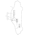
図1において、符号1は自動車などの車輌であり、この車輌1に、車外の対象を撮像し、撮像した画像を処理して外界情報を得る車外監視装置2が搭載されている。
【0011】
前記車外監視装置2は、車外の対象を近距離から遠距離に渡って撮像可能な撮像手段10と、この撮像手段10によって撮像した画像を撮像時の焦点距離に基づいて処理し、画像全体に渡る距離分布を算出して外界情報を得る画像処理手段20と、車速センサ5で検出した車輌1の車速に応じて適正な焦点距離を設定し、この焦点距離の設定値を前記撮像手段10及び前記画像処理手段20へ出力して撮像手段10を広角用または望遠用に切り換える焦点距離設定手段15とを備えている。
【0012】
前記画像処理手段20で得られる外界情報としては、先ず、車外の対象までの距離情報があり、この距離情報に基づいて道路形状や立体物等の認識が行われる。そして、認識した立体物が自車輌に対して障害物となる場合、図示しないアクチュエータ類を制御する外部装置を接続することにより、運転者に対する警告、車体の自動衝突回避等の動作を行うことが可能となっている。
【0013】
本実施形態の車外監視装置2は、車外の対象を異なる位置から撮像した1組の画像に対し、対応する位置のずれ量から三角測量の原理によって距離を求める、いわゆるステレオ法による画像処理で三次元の距離情報を得るものであり、前記撮像手段10は、左右画像用として、例えば電荷結合素子(CCD)等の固体撮像素子を用いた2台のカメラにより構成されている。
【0014】
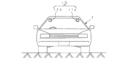
すなわち、図2に示すように、撮像手段10は、2台の撮像体としてのCCDカメラ11a,11b(代表してCCDカメラ11と表記する場合もある)を有し、各CCDカメラ11a,11bが、それぞれ車室内の天井前方に一定の間隔をもって取り付けられている。ここで、車室内のCCDカメラ11の取付位置を、例えば、車輌1のボンネット先端から2mとすると、例えば、直近から100m遠方までを撮像する場合、実際には前方2mから100mまでの位置を撮像することになる。
【0015】
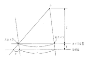
この場合、図3に示すように、2台のCCDカメラ11a、11bの取付間隔をrとして、2台のカメラ11a,11bの設置面から距離Zにある点Pを撮影すると、2台のカメラ11a,11bの焦点距離を共にfとして、点Pの像は、それぞれのカメラについて焦点位置からfだけ離れた投影面に写る。
【0016】
このとき、右のCCDカメラ11bにおける像の位置から左のCCDカメラ11aにおける像の位置までの距離は、r+δとなり、このδをずれ量とすると、点Pまでの距離Zは、ずれ量δから以下の(1)式で求めることができる。
【0017】
Z=r・f/δ (1)
この左右画像のずれ量δを検出するには、左右画像における同一物体の像を見つけ出す必要があり、本実施形態の画像処理手段20では、画像を小領域に分割し、それぞれの小領域内の輝度あるいは色のパターンを左右画像で比較して一致する領域を見つけ出し、全画面に渡って距離分布を求める。
【0018】
左右画像の一致度は、右画像、左画像のi番目画素の輝度(色を用いても良い)を、それぞれ、Ai、Biとすると、例えば、以下の(2)式に示すシティブロック距離Hによって評価することができる。
【0019】
H=Σ|Ai−Bi| (2)
前記一致度の評価を基に、撮像した画像の全画面に渡る距離分布を求め、得られた距離情報より車外の道路形状や立体物等の状態認識を行う。
【0020】
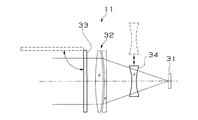
以下に本実施形態のCCDカメラ11の構成例を説明する。図4はCCDカメラ11の光学系の概略構成を示したものである。
【0021】
CCDカメラ11には、撮像素子としてCCD31が設けられ、このCCD31の前方に被写体像をCCD31の撮像面に結像する撮像光学系としての対物レンズ系32が配置されている。対物レンズ系32の前面部には、所定の偏光成分の光線のみを透過して不要な光線を除去する偏光フィルタ33が光路中に挿脱自在に設けられている。また、対物レンズ系32の光路中(図では対物レンズ系32の後面部)には、該対物レンズ系32の焦点距離を変更する焦点切換レンズとしてのコンバージョンレンズ34が挿脱自在に設けられている。なお、図中の各レンズは模擬的に描いたものであり、実際のものとは異なっている。
【0022】
上記のように、CCDカメラ11において必要に応じて偏光フィルタ33を設けることにより、フロントウィンドウに映り込んだ車室内のインストルメントパネル上部やダッシュボードなどの物体の反射像のゴーストが対物レンズ系32及びCCD31に入射することを防ぐことができ、CCDカメラ11へのゴーストの映り込みを低減できる。また、必要に応じてコンバージョンレンズ34を設けることにより、広角用と望遠用の二種類の光学系を構成でき、一つのカメラで広い視野角を持つ画像と遠方の詳細な画像とを得ることができる。
【0023】
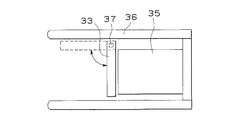
図5は前記CCDカメラ11の実際の車輛における設置例を示したものであり、CCDカメラ11のレンズ部35の周囲に、前方に突出して遮光用のフード36が設けられ、レンズ部35の前面に、偏光フィルタ33が上部のルーフ側の回動軸37を中心にして、光路に交差する方向(図5の矢印方向)へ回動可能に取り付けられている。偏光フィルタ33を配置すると、CCDカメラ11への入射光量が減少するため、ゴーストの影響が少なく必要の無いときは、偏光フィルタ33を図中破線で示すように対物レンズ系32の光路中から外すようにする。
【0024】
本設置例のように回動軸37を上部のルーフ側に設けることにより、偏光フィルタ33の退避時にフィルタ上に埃が付着しにくくすることができる。なお、図5の例とは逆に、下側に偏光フィルタ33の回動軸37を設けることもでき、この場合、偏光フィルタ33の退避時にフィルタ自体が下側のフードの代わりの機能を持つため、長いフードを設けなくともフロントウィンドウ下部のダッシュボード近傍等、下方からの映り込みを防止するのに有効である。
【0025】
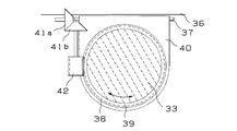
前記偏光フィルタ33の回転機構の構成例を図6に示す。偏光フィルタ33は、外周部にウォームホイル38を備えたフィルタ枠39に固定され、このフィルタ枠39と共にフィルタケース40に対し、光軸回り方向(図6の矢印方向)へ回転可能に取り付けられている。そして、フィルタケース40の一端に前記回動軸37が設けられ、フィルタケース40全体が回動軸37を中心に回動するようになっている。フィルタケース40の端部近傍には、図示しないモータ等の駆動手段に連結された一組のかさ歯車41a,41bが設けられ、かさ歯車41bの他端にピニオン42が設けられており、このピニオン42が前記フィルタ枠39のウォームホイル38に噛合している。ここで、かさ歯車41aの回転軸は、フィルタケース40の回動軸37の延長上に軸が一致するよう配置され、この軸に対して垂直にかさ歯車41bの回転軸が配置されている。
【0026】
このような回転機構によって、かさ歯車41aを回転させることにより、かさ歯車41b,ピニオン42,ウォームホイル38を介してフィルタ枠39を回転させ、フィルタケース40自体の回転位置によらず、偏光フィルタ33を所望の偏光角度となるよう位置させることができ、効果的にゴーストの偏光成分を除去できる。
【0027】
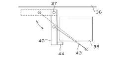
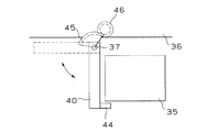
前記偏光フィルタ33の挿脱機構の構成例を図7及び図8に示す。図7に示す第1の構成例では、フィルタケース40を押引駆動するアクチュエータ43が設けられ、アクチュエータ43の一端がフィルタケース40の中間部に接続され、他端はフード等に固定されている。レンズ部35前端の下部近傍には、偏光フィルタ33の移動範囲を規制する位置決め用のストッパ44が配置されている。図8に示す第2の構成例では、フィルタケース40の回動軸37に扇形歯車45が取り付けられ、図示しないモータ等の駆動手段に連結された平歯車46に噛合している。
【0028】
このようなアクチュエータまたは歯車からなる挿脱機構によって、フィルタケース40を駆動して回動させ、偏光フィルタ33をレンズ部35の光路中にストッパ44で位置決めしてセットしたり、光路中から退避させたりすることができる。
【0029】
ステレオ法による画像認識では、前述したように同一の対象を左右のカメラで撮像し、一組の画像に対し左右方向の画像のズレを検出して対象の距離情報を得るようになっている。ゴーストによって左右のカメラに異なる画像が撮像された場合、ゴーストを除去しないと画像判定時にミスマッチが起き、誤認識してしまうおそれがある。車内にCCDカメラを設置した構成の場合、特に、フロントウィンドウ近傍において昼間の真上から照る光の反射光によるゴーストが多く発生するため、正常な画像認識を行うにはこのようなゴーストの影響を除去する必要がある。
【0030】
本実施形態では、画像処理手段20において、画像認識の際に左右の画像のミスマッチを検出して、ミスマッチがあった場合にゴーストが発生したと判断し、偏光フィルタ33によってゴーストの影響を除去する。画像処理手段20は、ゴーストの有無に応じてCCDカメラ11へ指示を送って偏光フィルタ33を対物レンズ系32の前面に挿入、退避させる。このとき、図7または図8に示すような挿脱機構によって偏光フィルタ33を光路中に配置させると共に、図6に示すような回転機構によって偏光フィルタ33を回転させ、適正な偏光位置となるように偏光フィルタ33をセットする。この偏光位置合わせは、所定の範囲内で偏光フィルタ33を少しずつ回転させながら撮像された画像の認識を行い、ゴーストの影響の少ない最適位置を求めるようにする。
【0031】
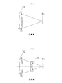
次に、前記コンバージョンレンズ34の作用を図9に基づいて説明する。本実施形態では、CCDカメラ11の対物レンズ系32を予め広角用に設定しておき、図9の(a)に示すように近距離の対象について広い視野角を確保できるようにする。遠距離の対象を詳細に観察する場合は、図9の(b)に示すように対物レンズ系32の光路中にコンバージョンレンズ34を挿入し、望遠用の光学系を構成する。この場合、コンバージョンレンズ34は凹レンズ系のもので構成され、対物レンズ系32の焦点距離を延長する作用を持っている。
【0032】
なお、図9の例において広角側と望遠側とを逆にして、対物レンズ系32を予め望遠用に設定しておき、広角用の光学系を構成する場合には対物レンズ系32の光路中に焦点距離を短縮する作用を持った凸レンズ系のコンバージョンレンズを挿入するような構成としても良い。
【0033】
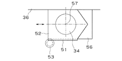
前記コンバージョンレンズ34の挿脱機構の構成例を図10及び図11に示す。図10に示す第1の構成例では、コンバージョンレンズ34は一側部にラック51を備えたレンズケース52に固定され、このレンズケース52のラック51が図示しないモータ等の駆動手段に連結されたピニオン53に噛合しており、レンズケース52が図中左右方向に移動可能になっている。なお、左右方向に限らず、上下方向に移動可能な構成としても良い。
【0034】
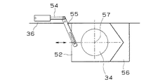
図11に示す第2の構成例では、レンズケース52を左右または上下方向に押引駆動するアクチュエータ54及びリンク55が設けられ、リンク55の一端がレンズケース52の一端部に接続され、他端はフード等に固定されたアクチュエータ54に接続されている。
【0035】
前記レンズケース52は、挿入方向側の端部が三角状に突出した形状に形成されており、このレンズケース52の挿入方向には、前記突出部と当接し係合する三角状の凹部を有しコンバージョンレンズ34の移動範囲を規制する位置決め用のストッパ56が配置されている。図のようにレンズケース52がストッパ56に当接した位置において、コンバージョンレンズ34の光軸57と対物レンズ系32の光軸中心とが一致するようになっており、ストッパ56にレンズケース52を押し当てることによって自動的に光軸合わせを行うことができる。
【0036】
広角用と望遠用との切換えは、車速センサ5で検出した車速に応じて、焦点距離設定手段15によりCCDカメラ11へ指示を送って図10または図11に示すような挿脱機構を駆動し、コンバージョンレンズ34を光路中に挿入、退避させる。例えば、時速40kmを境にして、時速40km以下の低速時は広角側に、時速40kmより速い高速時は望遠側に、それぞれ対物レンズ系32の焦点距離をセットする。
【0037】
以上のように本実施形態によれば、一組のCCDカメラのみで、広角用と望遠用のカメラを構成でき、外界認識の際に、近点においてより広い視野角を確保することができ、かつ、遠点においてより詳細な画像認識を行うことが可能となる。従って、ステレオ法による外界監視用の画像認識システムにおいて、広角用と望遠用とに専用の複数組のカメラを設けることなく、低コストでこれら二つの特性を有する撮像手段を実現でき、近距離から遠距離まで幅広く対応可能で、状況に応じて十分な視野角と解像度を持った外界の画像を得ることができる。
【0038】
また、画像認識の際に、本実施形態の偏光フィルタによってフロントウィンドウの反射光の映り込みをより効果的に低減でき、ゴーストによる誤認識を防止することができる。また、偏光フィルタを配設する対物レンズ系の周囲に保護用のフードを設けることにより、ゴースト除去効果を強化させることができる。また、偏光フィルタの退避時に、フィルタを上側に格納することにより、偏光フィルタへの埃等の付着を防止することができる。
【0039】
【発明の効果】
以上説明したように本発明によれば、広い視野角を得るための広角用と詳細な画像を得るための望遠用の二つの特性を有する撮像手段を低コストで実現できる効果がある。また、フロントウィンドウに映り込むゴーストの影響を低減でき、ゴーストによる誤認識を防止できる効果がある。
【図面の簡単な説明】
【図1】車外監視装置の全体構成図
【図2】車輛の正面図
【図3】カメラと被写体との関係を示す説明図
【図4】本発明の一実施形態に係るカメラの光学系の概略構成を示す説明図
【図5】カメラの実際の車輛における設置例を示す説明図
【図6】偏光フィルタの回転機構の構成例を示す平面図
【図7】偏光フィルタの挿脱機構の第1の構成例を示す説明図
【図8】偏光フィルタの挿脱機構の第2の構成例を示す説明図
【図9】本実施形態に係るカメラの光学系の作用説明図
【図10】コンバージョンレンズの挿脱機構の第1の構成例を示す説明図
【図11】コンバージョンレンズの挿脱機構の第2の構成例を示す説明図
【符号の説明】
1…車輌
2…車外監視装置
5…車速センサ
10…撮像手段
11…CCDカメラ
15…焦点距離設定手段
20…画像処理手段
31…CCD
32…対物レンズ系
33…偏光フィルタ
34…コンバージョンレンズ[0001]
BACKGROUND OF THE INVENTION
The present invention relates to a camera for a vehicle external monitoring device for capturing an object outside a vehicle in a vehicle such as an automobile, and obtaining external information by performing image recognition of the imaged object.
[0002]
[Prior art]
2. Description of the Related Art In recent years, a comprehensive driving assistance system (ADA, Active Drive Assist System) that actively assists driving operations has been developed in order to drastically improve vehicle safety against an increasing trend of traffic accidents. In this system, it is indispensable to recognize the external environment of the vehicle. Conventionally, an imaging means such as a camera is installed in the vehicle, and the image information of the scenery and objects in front of the vehicle captured by multiple cameras is processed. Therefore, development of technology for recognizing and monitoring conditions outside the vehicle, such as roads and traffic environments, is underway. For example, Japanese Patent Laid-Open No. 3-225513 discloses a technique for performing road control by extracting road information by performing image processing on a road belt image ahead in the traveling direction captured by a television camera.
[0003]
When monitoring outside the vehicle, it is important to obtain a wider viewing angle and to obtain a more detailed image in order to improve the external recognition rate and enhance safety. In general, it is possible to improve the external recognition rate by securing a wider field of view at low speeds and monitoring distant areas at high speeds. For this purpose, an appropriate focal length according to the vehicle speed is used. It is necessary to image an object outside the vehicle and perform image processing based on the focal length at the time of imaging.
[0004]
[Problems to be solved by the invention]
In the conventionally proposed external monitoring system, in order to image an object outside the vehicle with an appropriate focal length according to the vehicle speed, a wide angle for obtaining a wide field of view image at a low speed and a distant detail at a high speed are used. Two types of cameras are required for telephoto use to obtain images. In a so-called stereo method image recognition system that uses two cameras to perform stereo observation and recognizes objects in three dimensions, a total of four cameras, two for wide-angle use and one for telephoto use, are prepared to achieve the above objective. Therefore, there is a problem that the imaging means is expensive.
[0005]
In addition, when an imaging camera is installed in the vehicle interior, a ghost is generated in which a reflection image of an object such as a dashboard or instrument panel in the vehicle interior is reflected on the front window, and this ghost is incident on the camera and captured. Such a ghost may cause a recognition error or misrecognition such as recognizing a state different from the actual state.
[0006]
The present invention has been made in view of these circumstances, and a first object of the invention is to provide an imaging means having two characteristics for a wide angle for obtaining a wide viewing angle and for a telephoto for obtaining a detailed image. An object of the present invention is to provide a camera for a vehicle external monitoring device that can be realized at low cost.
[0007]
Another object of the present invention is to provide a camera for a vehicle external environment monitoring device that can reduce the influence of a ghost reflected on the front window and prevent erroneous recognition due to the ghost.
[0008]
[Means for Solving the Problems]
The present invention provides a camera for an external environment monitoring device for a vehicle that captures an image of an object outside a vehicle by using an image capturing unit including two image capturing bodies and processes the image captured by the image capturing unit to obtain external environment information. In the optical path of the imaging optical system that forms a subject image with respect to the imaging device provided in the above, a polarization filter that transmits only the light of a predetermined polarization component among the light incident on the imaging optical system is detachably provided, The image processing means for detecting a mismatch between a pair of images taken by the two imaging bodies, and the image processing means sets the polarizing filter in the optical path and detects the polarization when detecting the mismatch. The filter is rotated around the optical axis, and the polarization angle of the polarizing filter is set at a position where there is little mismatch between the images .
[0009]
DETAILED DESCRIPTION OF THE INVENTION
Embodiments of the present invention will be described below with reference to the drawings.
1 to 11 relate to an embodiment of the present invention, FIG. 1 is an overall configuration diagram of a vehicle outside monitoring device, FIG. 2 is a front view of a vehicle, FIG. 3 is an explanatory diagram showing a relationship between a camera and a subject, FIG. Is an explanatory diagram showing a schematic configuration of the optical system of the camera, FIG. 5 is an explanatory diagram showing an example of installation of the camera in an actual vehicle, FIG. 6 is a plan view showing an example of the configuration of the rotating mechanism of the polarizing filter, and FIG. FIG. 8 is an explanatory view showing a second configuration example of the polarization filter insertion / removal mechanism, FIG. 9 is an operation explanatory view of the optical system of the camera, and FIG. FIG. 11 is an explanatory diagram showing a second configuration example of the conversion lens insertion / removal mechanism.
[0010]
In FIG. 1,
[0011]
The vehicle exterior monitoring device 2 processes an image captured by the
[0012]
The external information obtained by the image processing means 20 includes distance information to a target outside the vehicle. Based on the distance information, a road shape, a three-dimensional object, and the like are recognized. When the recognized three-dimensional object becomes an obstacle to the host vehicle, an external device that controls actuators (not shown) can be connected to perform operations such as warning to the driver and automatic collision avoidance of the vehicle body. It is possible.
[0013]
The vehicle exterior monitoring device 2 according to the present embodiment uses a so-called stereo method of image processing to obtain a distance from a set of images obtained by capturing an object outside the vehicle from different positions based on the principle of triangulation from a corresponding position shift amount. The original distance information is obtained, and the imaging means 10 is composed of two cameras using a solid-state imaging device such as a charge coupled device (CCD) for left and right images.
[0014]
That is, as shown in FIG. 2, the
[0015]
In this case, as shown in FIG. 3, when the mounting interval between the two CCD cameras 11a and 11b is r and a point P located at a distance Z from the installation surface of the two cameras 11a and 11b is photographed, the two cameras Let f be the focal lengths of 11a and 11b, and the image of the point P appears on the projection plane separated by f from the focal position for each camera.
[0016]
At this time, the distance from the position of the image in the right CCD camera 11b to the position of the image in the left CCD camera 11a is r + δ. If this δ is the amount of deviation, the distance Z to the point P is calculated from the amount of deviation δ. It can be obtained by the following equation (1).
[0017]
Z = r · f / δ (1)
In order to detect the shift amount δ of the left and right images, it is necessary to find an image of the same object in the left and right images. In the image processing means 20 of the present embodiment, the image is divided into small regions, The luminance or color pattern is compared between the left and right images to find a matching area, and the distance distribution is obtained over the entire screen.
[0018]
The degree of coincidence between the left and right images is, for example, the city block distance H shown in the following equation (2), where the luminance (color may be used) of the i-th pixel of the right image and the left image is Ai and Bi, respectively. Can be evaluated.
[0019]
H = Σ | Ai−Bi | (2)
Based on the evaluation of the degree of coincidence, a distance distribution over the entire screen of the captured image is obtained, and a road shape outside the vehicle, a three-dimensional object, and the like are recognized from the obtained distance information.
[0020]
A configuration example of the CCD camera 11 of the present embodiment will be described below. FIG. 4 shows a schematic configuration of the optical system of the CCD camera 11.
[0021]
In the CCD camera 11, a
[0022]
As described above, by providing the
[0023]
FIG. 5 shows an installation example of the CCD camera 11 in an actual vehicle. A light-shielding
[0024]
By providing the
[0025]
A configuration example of the rotation mechanism of the
[0026]
By rotating the bevel gear 41a by such a rotation mechanism, the
[0027]
A configuration example of an insertion / removal mechanism for the
[0028]
The
[0029]
In the image recognition by the stereo method, as described above, the same object is imaged by the left and right cameras, and the distance information of the object is obtained by detecting the deviation of the image in the left-right direction with respect to a set of images. When different images are captured by the left and right cameras due to the ghost, if the ghost is not removed, a mismatch may occur at the time of image determination, and there is a risk of erroneous recognition. In the case of a configuration in which a CCD camera is installed in the car, particularly ghosts due to reflected light of light that shines from directly above in the daytime occur near the front window. Need to be removed.
[0030]
In the present embodiment, the image processing means 20 detects a mismatch between the left and right images during image recognition, determines that a ghost has occurred when there is a mismatch, and removes the influence of the ghost by the
[0031]
Next, the operation of the
[0032]
In the example of FIG. 9, when the wide-angle side and the telephoto side are reversed and the
[0033]
A configuration example of the insertion / removal mechanism of the
[0034]
In the second configuration example shown in FIG. 11, an
[0035]
The
[0036]
Switching between wide-angle use and telephoto use is performed by sending an instruction to the CCD camera 11 by the focal length setting means 15 according to the vehicle speed detected by the vehicle speed sensor 5 to drive the insertion / removal mechanism as shown in FIG. The
[0037]
As described above, according to the present embodiment, a wide-angle camera and a telephoto camera can be configured with only one set of CCD cameras, and a wider viewing angle can be secured at a near point when the outside world is recognized. In addition, more detailed image recognition can be performed at a far point. Therefore, in the image recognition system for monitoring the outside world by the stereo method, an imaging means having these two characteristics can be realized at a low cost without providing a plurality of dedicated cameras for wide-angle use and telephoto use. It can handle a wide range up to a long distance and can obtain an image of the outside world with a sufficient viewing angle and resolution depending on the situation.
[0038]
In addition, when the image is recognized, the reflected light of the front window can be more effectively reduced by the polarizing filter of the present embodiment, and erroneous recognition due to ghost can be prevented. Further, the ghost removal effect can be enhanced by providing a protective hood around the objective lens system in which the polarizing filter is provided. Further, by storing the filter on the upper side when the polarizing filter is retracted, dust or the like can be prevented from adhering to the polarizing filter.
[0039]
【The invention's effect】
As described above, according to the present invention, there is an effect that an imaging unit having two characteristics for a wide angle for obtaining a wide viewing angle and for a telephoto for obtaining a detailed image can be realized at low cost. Further, it is possible to reduce the influence of the ghost reflected on the front window and to prevent erroneous recognition due to the ghost.
[Brief description of the drawings]
FIG. 1 is an overall configuration diagram of a vehicle exterior monitoring device. FIG. 2 is a front view of a vehicle. FIG. 3 is an explanatory diagram showing a relationship between a camera and a subject. FIG. 4 is an optical system of a camera according to an embodiment of the invention. FIG. 5 is an explanatory diagram showing an example of installation of the camera in an actual vehicle. FIG. 6 is a plan view showing a configuration example of a rotating mechanism of the polarizing filter. FIG. FIG. 8 is a diagram illustrating a second configuration example of a polarization filter insertion / removal mechanism. FIG. 9 is a diagram illustrating the operation of the optical system of the camera according to the present embodiment. FIG. 11 is a diagram illustrating a first configuration example of a lens insertion / removal mechanism. FIG. 11 is a diagram illustrating a second configuration example of a conversion lens insertion / removal mechanism.
DESCRIPTION OF
32 ...
Claims (4)
上記撮像手段に設けた撮像素子に対し被写体像を結像する撮像光学系の光路中に、該撮像光学系に入射する光線のうち所定の偏光成分の光線のみを透過する偏光フィルタを挿脱自在に設け、
上記両撮像体で撮像した一対の画像同士のミスマッチを検出する画像処理手段を有し、
上記画像処理手段は、上記ミスマッチを検出した際、上記偏光フィルタを上記光路中にセットさせると共に、上記偏光フィルタを光軸回りに回転させて該偏光フィルタの偏光角度を上記画像同士のミスマッチが少ない位置にセットする
ことを特徴とする車輛の外界監視装置用カメラ。 In a camera for an external environment monitoring device for a vehicle that captures an object outside a vehicle using an imaging unit composed of two imaging bodies and processes the image captured by the imaging unit to obtain external environment information.
In the optical path of the imaging optical system that forms a subject image on the imaging device provided in the imaging means, a polarizing filter that transmits only a predetermined polarization component of the light incident on the imaging optical system can be freely inserted and removed. Provided in
Image processing means for detecting a mismatch between a pair of images captured by the two imaging bodies,
When the image processing unit detects the mismatch, the image processing unit sets the polarizing filter in the optical path and rotates the polarizing filter around the optical axis so that the polarization angle of the polarizing filter is small between the images. A camera for a vehicle external monitoring device, characterized by being set at a position .
上記偏光フィルタをフィルタケースに取り付けると共に該偏光フィルタを上記光路に対して挿脱する挿脱機構を設け、
上記挿脱機構を上記フィルタケースの一端を支持する回動軸を中心として該フィルタケースを上記光路に交差する方向へ回転させて上記偏光フィルタを該光路中にセット或いは退避させる構成とし、
上記回動軸を上部のルーフ側に設けると共に上記フィルタケースを該ルーフ側に回転させて格納する
ことを特徴とする請求項1記載の車輛の外界監視装置用カメラ。 A light shielding hood is provided around the lens portion of the imaging body,
Attaching / detaching the polarizing filter to / from the optical path and attaching / detaching the polarizing filter to / from the optical path,
The insertion / removal mechanism is configured to rotate the filter case in a direction intersecting the optical path around a rotation shaft that supports one end of the filter case to set or retract the polarizing filter in the optical path,
The camera for an external environment monitoring device for a vehicle according to claim 1 , wherein the rotating shaft is provided on an upper roof side and the filter case is rotated and stored on the roof side .
ことを特徴とする請求項1或いは2記載の車輌の外界監視装置用カメラ。 A focus switching lens for switching the focal length of the optical system between telephoto and wide-angle is detachably provided in the optical path of the imaging optical system that forms a subject image on the imaging device provided in the imaging means.
The camera for an external environment monitoring device for a vehicle according to claim 1 or 2 .
上記撮像手段に設けた撮像素子に対し被写体像を結像する撮像光学系の光路中に、該撮像光学系に入射する光線のうち所定の偏光成分の光線のみを透過する偏光フィルタを設け、
上記両撮像体で撮像した一対の画像同士のミスマッチを検出する画像処理手段を有し、
上記画像処理手段は、上記ミスマッチを検出した際、上記偏光フィルタを光軸回りに回転させて該偏光フィルタの偏光角度を上記画像同士のミスマッチが少ない位置にセットする
ことを特徴とする車輛の外界監視装置用カメラ。 In a camera for an external environment monitoring device for a vehicle that captures an object outside a vehicle using an imaging unit composed of two imaging bodies and processes the image captured by the imaging unit to obtain external environment information.
In the optical path of the imaging optical system that forms a subject image on the imaging device provided in the imaging means, a polarizing filter that transmits only a light beam having a predetermined polarization component among the light beams incident on the imaging optical system is provided.
Image processing means for detecting a mismatch between a pair of images captured by the two imaging bodies,
The image processing means, when detecting the mismatch, rotates the polarizing filter around the optical axis and sets the polarization angle of the polarizing filter at a position where the mismatch between the images is small. Camera for the outside world monitoring device.
Priority Applications (1)
| Application Number | Priority Date | Filing Date | Title |
|---|---|---|---|
| JP07428096A JP3630833B2 (en) | 1996-03-28 | 1996-03-28 | Camera for external vehicle monitoring equipment |
Applications Claiming Priority (1)
| Application Number | Priority Date | Filing Date | Title |
|---|---|---|---|
| JP07428096A JP3630833B2 (en) | 1996-03-28 | 1996-03-28 | Camera for external vehicle monitoring equipment |
Publications (2)
| Publication Number | Publication Date |
|---|---|
| JPH09266572A JPH09266572A (en) | 1997-10-07 |
| JP3630833B2 true JP3630833B2 (en) | 2005-03-23 |
Family
ID=13542553
Family Applications (1)
| Application Number | Title | Priority Date | Filing Date |
|---|---|---|---|
| JP07428096A Expired - Fee Related JP3630833B2 (en) | 1996-03-28 | 1996-03-28 | Camera for external vehicle monitoring equipment |
Country Status (1)
| Country | Link |
|---|---|
| JP (1) | JP3630833B2 (en) |
Families Citing this family (8)
| Publication number | Priority date | Publication date | Assignee | Title |
|---|---|---|---|---|
| JP2001094842A (en) * | 1999-09-22 | 2001-04-06 | Fuji Heavy Ind Ltd | Prevention of glare in vehicle cameras |
| DE10059313A1 (en) * | 2000-11-29 | 2002-06-13 | Bosch Gmbh Robert | Arrangement and method for monitoring the surroundings of a vehicle |
| JP5467680B2 (en) * | 2009-11-12 | 2014-04-09 | ストアネット株式会社 | Method for manufacturing filter member of polarizing filter for monitoring device |
| JP5867807B2 (en) * | 2010-12-08 | 2016-02-24 | 株式会社リコー | Vehicle identification device |
| JP2012247356A (en) * | 2011-05-30 | 2012-12-13 | Canon Inc | Imaging module, imaging apparatus, image processing apparatus, and image processing method |
| JP6388105B2 (en) | 2013-02-22 | 2018-09-12 | パナソニックIpマネジメント株式会社 | Camera device and method of controlling camera device |
| JP2019032569A (en) * | 2013-08-06 | 2019-02-28 | パナソニックIpマネジメント株式会社 | Camera device and filter unit |
| JP6452085B2 (en) * | 2013-08-06 | 2019-01-16 | パナソニックIpマネジメント株式会社 | Camera device and filter unit |
-
1996
- 1996-03-28 JP JP07428096A patent/JP3630833B2/en not_active Expired - Fee Related
Also Published As
| Publication number | Publication date |
|---|---|
| JPH09266572A (en) | 1997-10-07 |
Similar Documents
| Publication | Publication Date | Title |
|---|---|---|
| JP7159802B2 (en) | Vehicle electronic mirror system | |
| EP3547678B1 (en) | Imaging device, imaging system, and display system | |
| JP6661691B2 (en) | Vehicle camera system, mirror replacement system including such a camera system, and driver assistance system including such a system | |
| JP5347257B2 (en) | Vehicle periphery monitoring device and video display method | |
| JP4766841B2 (en) | Camera device and vehicle periphery monitoring device mounted on vehicle | |
| JP4593070B2 (en) | Image processing apparatus for vehicle | |
| US20090143967A1 (en) | Motor Vehicle Having a Wheel-View Camera and Method for Controlling a Wheel-View Camera System | |
| JP6014433B2 (en) | Image processing apparatus, image processing method, and image processing system | |
| CN107082090A (en) | Vehicle surrounding image display device | |
| US11601621B2 (en) | Vehicular display system | |
| JP2009105656A (en) | In-vehicle imaging device | |
| US20240348749A1 (en) | Camera system, and method for generating a view using a camera system | |
| JP2017017480A (en) | Camera device and in-vehicle system | |
| JP7515011B2 (en) | Camera, A-pillar configuration, and vehicle | |
| CN108737778A (en) | Using reflector video camera is blocked to what wheel was monitored from vehicle lower side | |
| JP3630833B2 (en) | Camera for external vehicle monitoring equipment | |
| US7693302B2 (en) | Device for detecting obstacles comprising an imaging system for motor vehicles | |
| JPH0717328A (en) | Peripheral recognition assistance device for vehicles | |
| JP3807330B2 (en) | Vehicle periphery monitoring device | |
| JP6439233B2 (en) | Image display apparatus for vehicle and image processing method | |
| JP2002237969A (en) | In-vehicle camera and image processing system | |
| WO2013144998A1 (en) | Visual recognition assistance apparatus for vehicle | |
| CN112514361A (en) | Vehicle-mounted camera and drive control system using same | |
| US11938870B2 (en) | Vehicle compound-eye camera | |
| JP4211104B2 (en) | Multi-directional imaging device, in-vehicle lamp with multi-directional imaging device, collision monitoring device, forward monitoring device |
Legal Events
| Date | Code | Title | Description |
|---|---|---|---|
| A131 | Notification of reasons for refusal |
Free format text: JAPANESE INTERMEDIATE CODE: A131 Effective date: 20040921 |
|
| A521 | Request for written amendment filed |
Free format text: JAPANESE INTERMEDIATE CODE: A523 Effective date: 20041119 |
|
| TRDD | Decision of grant or rejection written | ||
| A01 | Written decision to grant a patent or to grant a registration (utility model) |
Free format text: JAPANESE INTERMEDIATE CODE: A01 Effective date: 20041214 |
|
| A61 | First payment of annual fees (during grant procedure) |
Free format text: JAPANESE INTERMEDIATE CODE: A61 Effective date: 20041215 |
|
| R150 | Certificate of patent or registration of utility model |
Free format text: JAPANESE INTERMEDIATE CODE: R150 |
|
| FPAY | Renewal fee payment (event date is renewal date of database) |
Free format text: PAYMENT UNTIL: 20071224 Year of fee payment: 3 |
|
| FPAY | Renewal fee payment (event date is renewal date of database) |
Free format text: PAYMENT UNTIL: 20081224 Year of fee payment: 4 |
|
| FPAY | Renewal fee payment (event date is renewal date of database) |
Free format text: PAYMENT UNTIL: 20081224 Year of fee payment: 4 |
|
| FPAY | Renewal fee payment (event date is renewal date of database) |
Free format text: PAYMENT UNTIL: 20091224 Year of fee payment: 5 |
|
| FPAY | Renewal fee payment (event date is renewal date of database) |
Free format text: PAYMENT UNTIL: 20101224 Year of fee payment: 6 |
|
| FPAY | Renewal fee payment (event date is renewal date of database) |
Free format text: PAYMENT UNTIL: 20101224 Year of fee payment: 6 |
|
| FPAY | Renewal fee payment (event date is renewal date of database) |
Free format text: PAYMENT UNTIL: 20111224 Year of fee payment: 7 |
|
| FPAY | Renewal fee payment (event date is renewal date of database) |
Free format text: PAYMENT UNTIL: 20111224 Year of fee payment: 7 |
|
| FPAY | Renewal fee payment (event date is renewal date of database) |
Free format text: PAYMENT UNTIL: 20121224 Year of fee payment: 8 |
|
| FPAY | Renewal fee payment (event date is renewal date of database) |
Free format text: PAYMENT UNTIL: 20121224 Year of fee payment: 8 |
|
| FPAY | Renewal fee payment (event date is renewal date of database) |
Free format text: PAYMENT UNTIL: 20131224 Year of fee payment: 9 |
|
| R250 | Receipt of annual fees |
Free format text: JAPANESE INTERMEDIATE CODE: R250 |
|
| S531 | Written request for registration of change of domicile |
Free format text: JAPANESE INTERMEDIATE CODE: R313531 |
|
| R350 | Written notification of registration of transfer |
Free format text: JAPANESE INTERMEDIATE CODE: R350 |
|
| R250 | Receipt of annual fees |
Free format text: JAPANESE INTERMEDIATE CODE: R250 |
|
| LAPS | Cancellation because of no payment of annual fees |