JP2009105656A - On-vehicle imaging apparatus - Google Patents
On-vehicle imaging apparatus Download PDFInfo
- Publication number
- JP2009105656A JP2009105656A JP2007275466A JP2007275466A JP2009105656A JP 2009105656 A JP2009105656 A JP 2009105656A JP 2007275466 A JP2007275466 A JP 2007275466A JP 2007275466 A JP2007275466 A JP 2007275466A JP 2009105656 A JP2009105656 A JP 2009105656A
- Authority
- JP
- Japan
- Prior art keywords
- vehicle
- image
- camera
- imaging device
- illustration
- Prior art date
- Legal status (The legal status is an assumption and is not a legal conclusion. Google has not performed a legal analysis and makes no representation as to the accuracy of the status listed.)
- Granted
Links
- 238000003384 imaging method Methods 0.000 title claims abstract description 38
- 238000001514 detection method Methods 0.000 claims description 21
- 238000000034 method Methods 0.000 claims description 18
- 239000000203 mixture Substances 0.000 claims description 5
- 238000006243 chemical reaction Methods 0.000 claims description 3
- 239000002131 composite material Substances 0.000 abstract description 5
- 230000015654 memory Effects 0.000 description 14
- 230000003287 optical effect Effects 0.000 description 11
- 238000010586 diagram Methods 0.000 description 6
- 208000019901 Anxiety disease Diseases 0.000 description 2
- 230000036506 anxiety Effects 0.000 description 2
- 239000003086 colorant Substances 0.000 description 2
- 239000004973 liquid crystal related substance Substances 0.000 description 2
- 230000015572 biosynthetic process Effects 0.000 description 1
- 238000009434 installation Methods 0.000 description 1
- 230000002093 peripheral effect Effects 0.000 description 1
- 238000011946 reduction process Methods 0.000 description 1
- 230000000717 retained effect Effects 0.000 description 1
- 238000003786 synthesis reaction Methods 0.000 description 1
- 230000000007 visual effect Effects 0.000 description 1
Images


Classifications
-
- H—ELECTRICITY
- H04—ELECTRIC COMMUNICATION TECHNIQUE
- H04N—PICTORIAL COMMUNICATION, e.g. TELEVISION
- H04N7/00—Television systems
- H04N7/18—Closed-circuit television [CCTV] systems, i.e. systems in which the video signal is not broadcast
- H04N7/181—Closed-circuit television [CCTV] systems, i.e. systems in which the video signal is not broadcast for receiving images from a plurality of remote sources
-
- B—PERFORMING OPERATIONS; TRANSPORTING
- B60—VEHICLES IN GENERAL
- B60R—VEHICLES, VEHICLE FITTINGS, OR VEHICLE PARTS, NOT OTHERWISE PROVIDED FOR
- B60R1/00—Optical viewing arrangements; Real-time viewing arrangements for drivers or passengers using optical image capturing systems, e.g. cameras or video systems specially adapted for use in or on vehicles
- B60R1/20—Real-time viewing arrangements for drivers or passengers using optical image capturing systems, e.g. cameras or video systems specially adapted for use in or on vehicles
- B60R1/22—Real-time viewing arrangements for drivers or passengers using optical image capturing systems, e.g. cameras or video systems specially adapted for use in or on vehicles for viewing an area outside the vehicle, e.g. the exterior of the vehicle
- B60R1/23—Real-time viewing arrangements for drivers or passengers using optical image capturing systems, e.g. cameras or video systems specially adapted for use in or on vehicles for viewing an area outside the vehicle, e.g. the exterior of the vehicle with a predetermined field of view
-
- B—PERFORMING OPERATIONS; TRANSPORTING
- B60—VEHICLES IN GENERAL
- B60R—VEHICLES, VEHICLE FITTINGS, OR VEHICLE PARTS, NOT OTHERWISE PROVIDED FOR
- B60R2300/00—Details of viewing arrangements using cameras and displays, specially adapted for use in a vehicle
- B60R2300/10—Details of viewing arrangements using cameras and displays, specially adapted for use in a vehicle characterised by the type of camera system used
- B60R2300/102—Details of viewing arrangements using cameras and displays, specially adapted for use in a vehicle characterised by the type of camera system used using 360 degree surveillance camera system
-
- B—PERFORMING OPERATIONS; TRANSPORTING
- B60—VEHICLES IN GENERAL
- B60R—VEHICLES, VEHICLE FITTINGS, OR VEHICLE PARTS, NOT OTHERWISE PROVIDED FOR
- B60R2300/00—Details of viewing arrangements using cameras and displays, specially adapted for use in a vehicle
- B60R2300/30—Details of viewing arrangements using cameras and displays, specially adapted for use in a vehicle characterised by the type of image processing
- B60R2300/303—Details of viewing arrangements using cameras and displays, specially adapted for use in a vehicle characterised by the type of image processing using joined images, e.g. multiple camera images
-
- B—PERFORMING OPERATIONS; TRANSPORTING
- B60—VEHICLES IN GENERAL
- B60R—VEHICLES, VEHICLE FITTINGS, OR VEHICLE PARTS, NOT OTHERWISE PROVIDED FOR
- B60R2300/00—Details of viewing arrangements using cameras and displays, specially adapted for use in a vehicle
- B60R2300/30—Details of viewing arrangements using cameras and displays, specially adapted for use in a vehicle characterised by the type of image processing
- B60R2300/304—Details of viewing arrangements using cameras and displays, specially adapted for use in a vehicle characterised by the type of image processing using merged images, e.g. merging camera image with stored images
-
- B—PERFORMING OPERATIONS; TRANSPORTING
- B60—VEHICLES IN GENERAL
- B60R—VEHICLES, VEHICLE FITTINGS, OR VEHICLE PARTS, NOT OTHERWISE PROVIDED FOR
- B60R2300/00—Details of viewing arrangements using cameras and displays, specially adapted for use in a vehicle
- B60R2300/60—Details of viewing arrangements using cameras and displays, specially adapted for use in a vehicle characterised by monitoring and displaying vehicle exterior scenes from a transformed perspective
- B60R2300/607—Details of viewing arrangements using cameras and displays, specially adapted for use in a vehicle characterised by monitoring and displaying vehicle exterior scenes from a transformed perspective from a bird's eye viewpoint
-
- B—PERFORMING OPERATIONS; TRANSPORTING
- B60—VEHICLES IN GENERAL
- B60R—VEHICLES, VEHICLE FITTINGS, OR VEHICLE PARTS, NOT OTHERWISE PROVIDED FOR
- B60R2300/00—Details of viewing arrangements using cameras and displays, specially adapted for use in a vehicle
- B60R2300/80—Details of viewing arrangements using cameras and displays, specially adapted for use in a vehicle characterised by the intended use of the viewing arrangement
- B60R2300/806—Details of viewing arrangements using cameras and displays, specially adapted for use in a vehicle characterised by the intended use of the viewing arrangement for aiding parking
Abstract
Description
本発明は、車両に複数のカメラが設けられ、このカメラで撮影された画像を合成して表示するものであり、特に車両とその外側の領域との境界部を認識しやすくした車載用撮像装置に関する。 The present invention is provided with a plurality of cameras on a vehicle, and combines and displays images captured by the cameras. In particular, the vehicle-mounted imaging device that makes it easy to recognize the boundary between the vehicle and an area outside the vehicle. About.
以下の各特許文献には、車両に複数のカメラを搭載した車載用撮像装置が開示されている。車両に設置されたそれぞれのカメラは、魚眼レンズのように広角の空間領域の画像を集光するレンズを備えており、このレンズで集光された画像をCCDなどの光検知素子で検知できるようにしている。 Each of the following patent documents discloses an in-vehicle imaging device in which a plurality of cameras are mounted on a vehicle. Each camera installed in the vehicle is equipped with a lens that collects an image of a wide-angle spatial region like a fisheye lens, and the image collected by this lens can be detected by a light detection element such as a CCD. ing.
これら車載用撮像装置では、複数のカメラで撮影された車両の外側の領域の画像を、上方から見た投影画像となるように合成し、この合成画像に、車両のイラスト画像を組み合わせて表示している。このように表示することで、車両とその周囲領域の関係を画面上で把握しやすくしている。 In these in-vehicle imaging devices, the images of the area outside the vehicle imaged by a plurality of cameras are combined so as to be a projected image viewed from above, and the vehicle illustration image is displayed in combination with this combined image. ing. By displaying in this way, the relationship between the vehicle and its surrounding area is easily grasped on the screen.
しかし、車両の複数箇所に設けたカメラで車両とその外側の領域との境界部を撮影する場合に、カメラがドアミラーなどに取り付けられて車両から離れた位置にあれば、画像を合成したときに、車両とその外側の領域との境界部をほぼ正確に表示することができる。しかし、車両の前端部や後端部に設置したカメラは、前記前端部や後端部よりもやや車両の中心部側に後退した位置に設けられるために、このカメラから前方や後方を見たときに、その手前に位置する車両の一部で前方領域や後方領域の一部が隠される領域が存在する。そのため、このカメラで撮影した画像を合成しても、車両の前端部や後端部の直近に位置する領域の画像を取得することができない。 However, when shooting the boundary between the vehicle and its outer area with cameras provided at multiple locations on the vehicle, if the camera is attached to a door mirror etc. The boundary between the vehicle and the area outside it can be displayed almost accurately. However, since the cameras installed at the front end and rear end of the vehicle are provided at a position retracted slightly toward the center of the vehicle from the front end and rear end, the front and rear are viewed from this camera. Sometimes, there is a region where a part of the front region and the rear region are hidden in a part of the vehicle located in front of the vehicle. For this reason, even if images captured by this camera are combined, an image of a region located in the immediate vicinity of the front end portion and the rear end portion of the vehicle cannot be acquired.
そこで、以下の特許文献3に記載された車載用撮像装置では、車両の直近の外側領域のうちの画像として取得できない領域を、死角領域または注意喚起領域として、この領域を特定の色で塗りつぶすなどの処理を行っている。
従来のように、車両の外側の周囲領域の合成画像と、車両のイラスト画像とを組み合わせる表示形態では、表示画面に、車両の外縁部としてイラスト画像の境界線が表示されるだけであるため、表示画面を見た操作者は、実際の車両の境界部を把握することが難しく、実際の車両の外縁部と障害物と間隔に不安を生じるおそれがある。また、表示画面に車両のイラスト画像を表示したものでは、例えば前輪の操舵角度を画像で確認することもできない。 As in the past, in the display form that combines the composite image of the surrounding area outside the vehicle and the illustration image of the vehicle, only the boundary line of the illustration image is displayed on the display screen as the outer edge of the vehicle. An operator who looks at the display screen has difficulty in grasping the boundary portion of the actual vehicle, and may cause anxiety about the distance between the outer edge portion of the actual vehicle and the obstacle. Further, in the case where an illustration image of a vehicle is displayed on the display screen, for example, the steering angle of the front wheels cannot be confirmed on the image.
また、特許文献3に記載のように、死角領域または注意喚起領域を特定の色で塗りつぶしてしまうと、表示画面を見た操作者にとって、塗りつぶされた部分がなにを意味しているのか、すなわち車両の一部であるのか、地面などを意味しているのかを直感で理解できなくなり、操作者らは、車両の外縁部の位置を把握するのが困難になる。
Also, as described in
本発明は、上記従来の課題を解決するものであり、複数のカメラで撮影した画像を合成して表示するときに、表示内容を見た操作者が、実際の車両とその外側領域との境界部を直接的に把握しやすい車載用撮像装置を提供することを目的としている。 The present invention solves the above-described conventional problems, and when an image taken by a plurality of cameras is combined and displayed, an operator who has viewed the display contents can recognize the boundary between the actual vehicle and its outer region. An object of the present invention is to provide an in-vehicle imaging device that can easily grasp the part directly.
第1の本発明は、車両の複数箇所に設けられたカメラと、複数のカメラで撮影された画像を処理する画像処理部と、前記画像処理部で処理された画像を表示する表示装置とを有する車載用撮像装置において、
前記カメラは広角な空間領域の画像を集光できるレンズと、前記レンズで集光された光を検知する光検知素子とを有し、それぞれの前記カメラは、車両から離れた領域から車両の一部までを撮影範囲とする向きで、前記車両に設置されており、
前記画像処理部では、それぞれのカメラで撮影された画像を、合成して表示する変換処理が行なわれるとともに、
合成された画像において車両に近接した周囲領域の画像が得られない画像不存在部分に、その画像不存在部分に向けられているカメラで撮影された車両の一部の実画像を当てはめて表示する合成処理が行われることを特徴とするものである。
According to a first aspect of the present invention, there are provided a camera provided at a plurality of locations of a vehicle, an image processing unit that processes images taken by the plurality of cameras, and a display device that displays an image processed by the image processing unit. In-vehicle imaging device having
The camera includes a lens that can collect an image of a wide-angle spatial region, and a light detection element that detects light collected by the lens, and each of the cameras is connected to a vehicle from a region away from the vehicle. It is installed in the vehicle with the orientation up to the shooting range,
In the image processing unit, a conversion process for combining and displaying images captured by the respective cameras is performed,
In the synthesized image, an actual image of a part of the vehicle photographed by the camera directed to the non-existing part is applied to the non-existing part where the image of the surrounding area close to the vehicle cannot be obtained and displayed. A synthesis process is performed.
本発明の車載用撮像装置では、カメラで撮影した画像が合成されて表示されるが、カメラの斜め前方の下側で且つ車両の直近に位置している地面などの外側領域の画像は車両の一部で遮られて取得することができない。そこで、画像を合成するときに、画像が得られていない画像不存在部分に、その部分を映しているカメラで取得された車両の一部を実画像としてそのまま表示する。つまり、画像不存在部分には、車両の一部を斜めに映した画像が当てはめられる。そのために、表示画面に、何も映らない領域を設けたり、一定の色で塗りつぶした領域を設けたりするような、不自然な表示状態となるのを防止できる。また、表示画面を見た操作者らは、車両の一部の実画像を直接見ることができるために、車両とその周囲領域との関係や、車両の近くにある障害物と車両との位置関係を把握しやすくなる。 In the in-vehicle imaging device of the present invention, images captured by the camera are combined and displayed, but the image of the outer region such as the ground located diagonally below the camera and in the immediate vicinity of the vehicle is Cannot be acquired by being blocked by some. Therefore, when the images are combined, a part of the vehicle acquired by the camera that reflects the image is displayed as it is as an actual image in an image nonexistent portion where no image is obtained. That is, an image in which a part of the vehicle is shown obliquely is applied to the image nonexistent portion. Therefore, it is possible to prevent an unnatural display state such as providing an area where nothing is displayed or an area filled with a certain color on the display screen. In addition, since the operator who viewed the display screen can directly view a part of the vehicle, the relationship between the vehicle and the surrounding area, and the position of the obstacle and the vehicle near the vehicle. It becomes easier to understand the relationship.
本発明は、前記画像処理部では、車両の外形を示すイラスト境界線を、合成した画像に組み合わせて表示する合成処理が行われ、
前記表示装置には、前記イラスト境界線と、前記画像不存在部分に当てはめられた車両の一部の実画像の、双方が表示されるものとして構成できる。
In the present invention, the image processing unit performs a combining process of displaying an illustration boundary line indicating the outer shape of the vehicle in combination with the combined image,
The display device can be configured to display both the illustration boundary line and a real image of a part of the vehicle applied to the image non-existing portion.
例えば、前記画像不存在部分に当てはめられる車両の一部の実画像は、車両の前端部の実画像と車両の後端部の実画像の少なくとも一方であり、前記イラスト境界線は、車両の右側端および左側端を示すものである。 For example, the actual image of a part of the vehicle applied to the image non-existing portion is at least one of an actual image at the front end of the vehicle and an actual image at the rear end of the vehicle, and the illustration boundary is on the right side of the vehicle An end and a left end are shown.
ここで「イラスト境界線」とは、画像を上方から見た状態に投影したときに、車両とそれよりも外側の領域との境界線のみをイラストで示したものである。このイラスト境界線で囲まれた範囲の内部は、車両の形状のイラストが描かれていてもよいし、または何も描かなかったり、あるいは一定の色で塗りつぶしてもよい。 Here, the “illustration boundary line” is an illustration showing only the boundary line between the vehicle and an area outside it when the image is projected from above. Inside the area surrounded by the illustration boundary line, an illustration of the shape of the vehicle may be drawn, or nothing may be drawn, or it may be filled with a certain color.
または、本発明は、前記画像処理部では、合成した画像に、車両のイラスト画像を組み合わせる合成処理が行われ、
前記表示装置には、前記車両のイラスト画像と、前記画像不存在部分に当てはめられた車両の一部の実画像の、双方が表示されるものとして構成される。
Alternatively, in the present invention, the image processing unit performs a combining process for combining a vehicle illustration image with the combined image,
The display device is configured to display both an illustration image of the vehicle and a real image of a part of the vehicle applied to the non-image-existing portion.
この場合も、前記画像不存在部分に当てはめられる車両の一部の実画像は、車両の前端部の実画像と車両の後端部の実画像の少なくとも一方であり、
前記表示装置には、車両の前端部と後端部の実画像の少なくとも一方とともに、車両のイラスト画像の右側端および左側端が表示される。
Also in this case, the real image of a part of the vehicle applied to the image non-existing portion is at least one of a real image of the front end portion of the vehicle and a real image of the rear end portion of the vehicle,
The display device displays at least one of a real image of a front end portion and a rear end portion of the vehicle, and a right end and a left end of an illustration image of the vehicle.
本発明での「車両のイラスト画像」とは、車両を上方から見たのとほぼ同じ大きさで、ほぼ同じ輪郭を持つ画像として作成されたものである。この輪郭の内側には、車両の窓やボンネットの形状を上方から見た画像が描かれている。あるいは、輪郭の内側に何も描かれておらず、一定の色で塗りつぶされていてもよい。 The “vehicle illustration image” in the present invention is created as an image having approximately the same size and the same outline as when the vehicle is viewed from above. Inside the outline, an image of the shape of the vehicle window and bonnet as viewed from above is drawn. Or nothing is drawn inside the outline, and it may be filled with a certain color.
この場合に、前記イラスト画像での車両の色と、前記画像不存在部分に当てはめられた車両の一部の実画像の色とが、同じ色相か、または同系の色相であることが好ましい。 In this case, it is preferable that the color of the vehicle in the illustration image and the color of a part of the actual image of the vehicle applied to the non-existing portion have the same hue or similar hues.
または、本発明は、前記画像不存在部分に向けられている前記カメラの他に、車両とその外側の周囲領域との境界部を撮影できる他のカメラが設けられており、
前記表示装置には、前記他のカメラで撮影された前記境界部の実画像と、前記画像不存在部分に当てはめられた車両の一部の実画像の、双方が表示される。
Alternatively, in the present invention, in addition to the camera directed to the image absence portion, another camera capable of photographing the boundary between the vehicle and the surrounding area outside the vehicle is provided,
The display device displays both an actual image of the boundary portion taken by the other camera and a real image of a part of the vehicle applied to the image non-existing portion.
そして、前記表示装置では、前記他のカメラで撮影された境界部の実画像と、前記画像不存在部分に当てはめられた車両の一部の実画像とで、車両の全周が表示されている。 And in the said display apparatus, the perimeter of a vehicle is displayed with the real image of the boundary part image | photographed with the said other camera, and the one part real image of the vehicle applied to the said image non-existing part. .
この場合に、前記他のカメラで撮影された境界部の実画像は、車両の右側端と左側端を示すものであり、前記画像不存在部分に当てはめられる車両の一部の実画像は、車両の前端部の実画像と後端部の実画像を示すものである。 In this case, the actual image of the boundary portion taken by the other camera shows the right end and the left end of the vehicle, and the actual image of a part of the vehicle applied to the image non-existing portion is the vehicle The real image of the front-end part and the real image of the rear-end part are shown.
例えば、前記他のカメラは、ドアミラーに取り付けられて、車両から離れた位置にあり、その結果、車両とその外側領域の地面などとの境界部を上方から直接に撮影できるものである。 For example, the other camera is attached to a door mirror and is located away from the vehicle. As a result, the boundary between the vehicle and the ground in the outer region can be directly photographed from above.
上記のように、車両の全周にカメラで撮影された実画像が存在していると、表示画面を見たときに、実際の車両とその周囲領域との関係を直接的な画像として把握できるようになる。 As described above, if there are real images taken by the camera all around the vehicle, the relationship between the actual vehicle and its surrounding area can be grasped as a direct image when viewing the display screen. It becomes like this.
また、上記手段では、前記他のカメラで撮影された境界部の実画像には、前輪の画像が含まれ、表示装置に、前輪の操舵方向が表示可能である。 In the above means, the actual image of the boundary portion taken by the other camera includes the image of the front wheel, and the steering direction of the front wheel can be displayed on the display device.
第2の本発明は、車両の複数箇所に設けられたカメラと、複数のカメラで撮影された画像を処理する画像処理部と、前記画像処理部で処理された画像を表示する表示装置とを有する車載用撮像装置において、
前記カメラは広角な空間領域の画像を集光できるレンズと、前記レンズで集光された光を検知する光検知素子とを有し、それぞれの前記カメラは、車両から離れた領域から車両の一部までを撮影範囲とする向きで、前記車両に設置されており、
前記画像処理部では、それぞれのカメラで撮影された画像のうちの、車両よりも外側の周囲領域の画像を合成して表示するとともに、合成した周囲領域の画像に、車両のイラスト画像を組み合わせて表示する合成処理が行われ、
合成された周囲領域の画像と前記イラスト画像との境界部の少なくとも一部に、いずれかのカメラで撮影された車両の一部の実画像を当てはめて表示する合成処理が行われることを特徴とするものである。
According to a second aspect of the present invention, there are provided a camera provided at a plurality of locations of a vehicle, an image processing unit that processes images captured by the plurality of cameras, and a display device that displays an image processed by the image processing unit. In-vehicle imaging device having
The camera includes a lens that can collect an image of a wide-angle spatial region, and a light detection element that detects light collected by the lens, and each of the cameras is connected to a vehicle from a region away from the vehicle. It is installed in the vehicle with the orientation up to the shooting range,
The image processing unit combines and displays the image of the surrounding area outside the vehicle among the images taken by the respective cameras, and combines the illustration image of the vehicle with the synthesized image of the surrounding area. The composition process to display is performed,
A composition process is performed in which a real image of a part of a vehicle photographed by any one of the cameras is applied to at least a part of a boundary portion between the synthesized image of the surrounding area and the illustration image. To do.
第2の本発明では、表示画面に車両のイラスト画像と、周囲領域の画像とを一緒に表示することで、車両の輪郭を把握できる。そして、車両と周囲領域との境界部分の少なくとも一部に車両の実画像を当てはめているため、車両の一部とその周囲の障害物などの位置関係を直接的に把握できるようになる。 In the second aspect of the present invention, the outline of the vehicle can be grasped by displaying the illustration image of the vehicle and the image of the surrounding area together on the display screen. Since the actual image of the vehicle is applied to at least a part of the boundary between the vehicle and the surrounding area, it is possible to directly grasp the positional relationship between a part of the vehicle and an obstacle around the vehicle.
例えば、前記車両の一部の実画像は、車両の前端部および後端部の少なくとも一方である。また、前記車両の一部の実画像は、車両の右側端と左側端の少なくとも一方である。 For example, the real image of a part of the vehicle is at least one of a front end portion and a rear end portion of the vehicle. The real image of a part of the vehicle is at least one of a right end and a left end of the vehicle.
第2の本発明では、前記車両の一部の実画像には、前輪の画像が含まれ、表示装置に、前輪の操舵方向が表示可能である。 In the second aspect of the present invention, the actual image of a part of the vehicle includes an image of the front wheel, and the steering direction of the front wheel can be displayed on the display device.
この場合も、前記車両のイラスト画像での車両の色と、車両の一部の実画像の色とが、同じ色相か、または同系の色相であることが好ましい。 Also in this case, it is preferable that the color of the vehicle in the illustration image of the vehicle and the color of a part of the actual image of the vehicle have the same hue or similar hues.
第1の本発明の車載用の撮像装置では、上方から見た状態に投影された合成画像において、車両に直近する周囲領域で且つカメラで取得できない画像不存在部分が発生しているときに、この部分にカメラで撮影された車両の一部の実画像を当てはめている。そのため、画像不存在部分に何も表示されないとか、車両やその外側領域の景色と全く無関係な塗りつぶし部が生じるような不自然な表示状態となるのを防止でき、車両とその外側の領域を自然な状態で表示できる。また、画像不存在部分に車両の一部の実画像が存在しているため、この実画像の車両と地面上の障害物などとの位置関係を直接的に把握しやすくなる。 In the in-vehicle imaging device according to the first aspect of the present invention, in the composite image projected in a state viewed from above, when an image nonexistent portion that cannot be acquired by the camera is generated in the surrounding area closest to the vehicle, A real image of a part of the vehicle photographed by the camera is applied to this portion. For this reason, it is possible to prevent an unnatural display state in which nothing is displayed in the image nonexistent part or a painted part completely unrelated to the scenery of the vehicle and its outer area is generated. Can be displayed. Further, since a part of the real image of the vehicle exists in the non-existing portion, it becomes easy to directly grasp the positional relationship between the vehicle of the real image and an obstacle on the ground.
第2の本発明の車載用の撮像装置では、合成された画像と、車両のイラスト画像とが表示されるものであって、車両のイラスト画像の少なくとも一部に車両の実画像を当てはめて表示している。よって、実画像の部分で、車両の外側に位置する障害物などと車両との位置関係を把握しやすくなる。 In the vehicle-mounted imaging device according to the second aspect of the present invention, a synthesized image and a vehicle illustration image are displayed, and the vehicle actual image is applied to at least a part of the vehicle illustration image for display. is doing. Therefore, it becomes easy to grasp the positional relationship between the obstacle and the like located outside the vehicle and the vehicle in the real image portion.
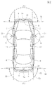
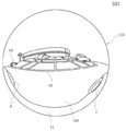
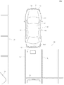
図1は車両でのカメラの配置を示す左側面図、図2はその平面図、図3はその正面図である。図4は、本発明の車載用撮像装置の実施の形態を示すブロック図である。図5は前カメラの光検知素子で受光した実画像、図6は後カメラの光検知素子で受光した実画像、図7は、左カメラの光検知素子で受光した実画像をそれぞれ示す説明図である。図8と図9は、表示装置の画面の表示内容の一例を示す説明図である。 1 is a left side view showing the arrangement of a camera in a vehicle, FIG. 2 is a plan view thereof, and FIG. 3 is a front view thereof. FIG. 4 is a block diagram showing an embodiment of an in-vehicle imaging device of the present invention. 5 is an actual image received by the light detection element of the front camera, FIG. 6 is an actual image received by the light detection element of the rear camera, and FIG. 7 is an explanatory view showing an actual image received by the light detection element of the left camera. It is. 8 and 9 are explanatory diagrams illustrating an example of display contents on the screen of the display device.
図1ないし図3には、自動車の車両1が示されているが、この車両1の図形は、表示装置の表示画面に表示される画像を意味しているのではなく、実際の自動車の車両を意味している。 1 to 3 show a vehicle 1 of an automobile. The figure of the vehicle 1 does not mean an image displayed on a display screen of a display device, but an actual vehicle of an automobile. Means.
車両1には、前端部2に前バンパー3が設けられ、後端部4に後バンパー5が設けられている。車両1の両側部には前輪7,7と後輪8,8が設けられている。車両1の両側部では、前輪7,7と後輪8,8との中間で且つ前輪7に寄った位置の上方に、ドアミラー6,6が設けられている。
The vehicle 1 is provided with a
車両1の前端部2に前カメラ21が設置されている。前カメラ21は車両1の前端部2において、車両の幅寸法の中心に位置している。図1と図2に示すように、前カメラ21は、車両1の最前端である前バンパー3の前端部3aよりもやや後方に位置している。車両1の後端部4には後カメラ22が設置されている。後カメラ22は車両1の後端部4において、車両の幅寸法の中心に位置している。図1と図2に示すように、後カメラ22は、車両1の最後端である後バンパー5の後端部5aよりもやや前方に位置している。
A
左側のドアミラー6には、左カメラ23が取り付けられており、右側のドアミラー6には右カメラ24が取り付けられている。図2に示すように、左カメラ23は、車両1の左側面11より左方へ離れた位置にあり、右カメラ24は、車両1の右側面12よりも右方へ離れた位置にある。
A
それぞれのカメラ21,22,23,24は、魚眼レンズと、魚眼レンズで集光された光を検知する複数の検知点を有する光検知素子(撮像素子)とを有している。光検知素子は、CCDまたはCMOSである。
Each of the
魚眼レンズは、複数枚のレンズが組み合わされて構成されている。魚眼レンズを使用したカメラ21,22,23,24の光検知素子で検知できる画角は広角であり、その画角は150度から180度の範囲または150度から190度の範囲程度にすることが可能である。
The fisheye lens is configured by combining a plurality of lenses. The angle of view that can be detected by the light detection elements of the
前カメラ21は、光軸が前方に向けられているとともに、光軸が地面100に向けて水平よりもやや下向きに傾斜するように設置されている。同様に、後カメラも、光軸が後方に向けられているとともに、光軸が地面100に向けて水平よりもやや下向きに傾斜するように設置されている。
The
図1では、前カメラ21の縦方向の画角がα1で示され、画角α1の視野の限界がY1で示されている。図2には、前カメラ21で撮影可能な地面100の横方向の視野の限界X1が示されている。この限界X1は、縦方向での画角の限界Y1と地面100との交線に相当している。この限界Y1の横方向の画角はβ1である。
In FIG. 1, the vertical field angle of the
同様に、図1には、後カメラ22の縦方向の画角がα2で示され、画角α2の視野の限界がY2で示されている。図2には、後カメラ22で撮影可能な地面100の横方向の視野の限界X2が示されている。この限界X2は、縦方向での画角の限界Y2と地面100との交線に相当している。この限界Y2の横方向の画角はβ2である。
Similarly, in FIG. 1, the vertical field angle of the
図3に示すように、左カメラ23と右カメラ24の光軸は、それぞれ右方向と左方向に向けられているが、それぞれの光軸は水平線に対して下向きに傾いて地面100に向くように設定されている。
As shown in FIG. 3, the optical axes of the
図3には、左カメラ23と右カメラ24のそれぞれの縦方向の画角がα3で示されているとともに、この画角α3の視野の限界がY3で示されている。また、図2では、左カメラ23と右カメラ24で撮影可能な地面100の横方向の視野の限界X3が示されている。この限界X3は、縦方向の限界Y3と地面100との交線に相当している。前記限界X3の横方向の画角はβ3である。前述のように、それぞれの画角α1,β1,α2,β2,α3,β3の最大値は、魚眼レンズの仕様にもよるが、180度程度であり、または190度やそれ以上の角度とすることも可能である。
In FIG. 3, the vertical field angles of the
図5は、前カメラ21の魚眼レンズで集光されて、複数の受光画素が平面的に配列したCCDなどの光検知素子で撮影された実画像121を示している。この実画像121には、画角α1とβ1の範囲で、車両1の前方の景色が映されている。ただし、図1に示すように、前カメラ21のレンズが、前バンパー3の前端部3aよりも後方に位置しているために、前端部3aに直近の地面100やその他の障害物などのように近接した周囲領域の画像は、その手前に位置する前バンパー3で隠されて取得することができない。
FIG. 5 shows an
図1では、前端部3aよりも前方の領域で且つ前カメラ21で取得できない領域をA1で示している。図2では、車両1の上方から地面に垂直な視線で下向きに見たときに、前カメラ21で取得できない前記領域を、破線を付してA1で示している。前記A1が、前方の画像不存在部分である。
In FIG. 1, an area that is in front of the
ただし、図5に示す実画像121では、前記画像不存在部分A1を斜め手前側から隠している車両1の一部である前バンパー3が映っている。
However, in the
図6は、後カメラ22の魚眼レンズで集光されてCCDなどの光検知素子で撮影された実画像122を示している。この実画像122には、前記画角α2,β2の範囲で、車両1の後方の景色が映されている。図1に示すように、後カメラ22のレンズは、後バンパー5の後端部5aよりもやや前方に配置されているため、後カメラ22で撮影される地面100やその他の障害物などのうちの、後バンパー5の後端部5aの直近の領域の画像を取得することができない。図1ではこの領域をB1で示し、図2でも破線を付した領域としてB1で示している。このB1の領域が、後方の画像不存在部分である。この画像不存在部分B1は、図2に示すように、全ての領域を地面100と垂直な視野で上方から見たときに本来は見えるはずの画像である。
FIG. 6 shows an
ただし、図6に示す実画像では、前記画像不存在部分B1よりも手前側から画像不存在部分B1を隠している後バンパー5の一部が映っている。
However, in the actual image shown in FIG. 6, a part of the
図6の実画像122では、車両1の後方において、地面100に印された白線91,91と、車両1の左側面11よりもさらに左側に離れた位置で、地面100に印された側方の白線92が歪んで映っている。また、車両1の真後ろに位置する他の自動車93の画像と、車両1の左斜め後方に位置する他の自動車94の画像も歪んで映っている。
In the
図7は、左カメラ23の魚眼レンズで集光されてCCDなどの光検知素子で撮像された実画像を示している。この映像の画角はα3とβ3の範囲である。図3に示すように、左カメラ23は、ドアミラー6に設置されて、車両1の左側面11から離れた位置にあり、且つレンズの光軸は、水平面よりもやや地面100に向く斜め下向きに設定されている。そのため、実画像123には、車両1の左側面11の下方部分の画像が前後方向の全域にわたって映っており、さらに、前輪7と後輪8も映っている。図3に示す画角の限界Y3からも明らかなように、図7に示す実画像123では、車両1と地面100との境界部、すなわち前輪7と地面100との接触部および後輪8と地面100との接触部が明確に映っている。
FIG. 7 shows an actual image that is collected by a fish-eye lens of the
図7に示す実画像123では、図1と図2に示す前方の画像不存在部分A1や後方の画像不存在部分B1のように、車両1の直近に位置する地面100の画像が欠落する領域が存在していない。
In the
また、図7に示す実画像123には、図6にも示されている車両1の左側方において地面100に記された側方の白線92と、車両1の左斜め後方に位置する他の自動車94の画像が映っている。
Further, the
図では省略しているが、右カメラ24で映された画像は、図7の画像と近似しており、車両1の右側面12の下方部分および、前輪7と後輪8が映されている。すなわち、車両1の右側面12と地面100との境界部である前輪7と地面100との接触部および後輪8と地面100との接触部も映されている。
Although omitted in the figure, the image shown by the
図4は、各カメラで撮像した画像を処理して表示するための回路構成を示すブロック図である。 FIG. 4 is a block diagram illustrating a circuit configuration for processing and displaying an image captured by each camera.
前カメラ21のCCDなどの光検知素子で検知された画像は画像メモリ31aに与えられて保持される。同様に、後カメラ22、左カメラ23および右カメラ24のそれぞれの光検知素子で検知された画像は、画像メモリ31b、画像メモリ31cおよび画像メモリ31dに与えられて保持される。
An image detected by a light detection element such as a CCD of the
それぞれのカメラ21,22,23,24の光検知素子で検知された画像信号は、それぞれの画像メモリ31a,31b,31c,31dから、各画素毎の画素データとして、画像処理部32に与えられる。画像処理部32には表示メモリ33が併設されており、リアルタイムで変化していく映像の各画素データが表示メモリ33に保持された後に画像処理部32で画像処理されていく。画像処理部32と表示メモリ33は、制御部34によって制御される。制御部34は、CPUを主体とするものであり、前記画像処理部32を制御するとともに、表示ドライバ35を制御する。画像処理部32で処理されて得られた画像データは、表示ドライバ35に送られ、車内に設けられた液晶表示パネルなどの表示パネル36に画像が表示される。
Image signals detected by the light detection elements of the
それぞれのカメラ21,22,23,24に使用されている魚眼レンズの一般的な射影モデルは、等距離射影であり、像高をraとし焦点距離をfとしたときに、ra=f・θiである。その他の魚眼レンズの射影モデルは、等立体角射影が、ra=2f・sin(θi/2)であり、正射影が、ra=f・sinθiである。
The general projection model of the fisheye lens used in each of the
カメラに設けられたCCDなどの平面状の光検知素子を撮像面とし、この撮像面の中心から垂直に延びる軸を光軸としたときに、魚眼レンズの射影モデルが分かれば、撮像面に結像している画像点の基となる空間点が、光軸に対してどの天頂角を有する線上に位置し、また光軸回りのどの方位角の位置に有るかを知ることができる。 If a planar light detection element such as a CCD provided in the camera is used as the imaging surface, and the axis extending perpendicularly from the center of the imaging surface is used as the optical axis, if the projection model of the fisheye lens is known, an image is formed on the imaging surface. It is possible to know on which zenith angle the spatial point that is the basis of the image point being located is located on the line having the zenith angle with respect to the optical axis, and at which azimuth angle around the optical axis.
したがって、カメラの設置位置と光軸の向きを知ることができれば、カメラの魚眼レンズの射影モデルに基づいて、図5ないし図7に示すそれぞれの画像のうちのどの部分をどの方向へどれだけ拡大すれば、その画像を地面100と平行な平面画像上に投影できるかを計算できる。すなわち、それぞれの画像メモリ31a,31b,31c,31dに保持されている画素データは、一度表示メモリ33で保持された後に、画像処理部32に与えられ、画像処理部32では、それぞれの画素データの座標位置に応じて拡大処理または縮小処理がなされ、それぞれの画素データが、地面100と平行な平面画像のそれぞれの位置に当てはめられて、平面的に投影された画像が合成される。
Accordingly, if the installation position of the camera and the direction of the optical axis can be known, based on the projection model of the fisheye lens of the camera, which part of each image shown in FIGS. For example, it can be calculated whether the image can be projected on a plane image parallel to the
図2に示すように、車両1の両側の左斜め前方では、前カメラ21で取得した画像と、左カメラ23で取得した画像とで重複する部分があり、右斜め前方では、前カメラ21で取得した画像と、右カメラ24で取得した画像とで重複する部分がある。同様に、車両1の左斜め後方には、後カメラ22で取得した画像と、左カメラ23で取得した画像とで重複する部分がある。図6に示す後カメラ22の実画像122と、図7に示す左カメラ23の実画像では、自動車94の画像と白線92の画像が、重複部分である。また、車両1の右斜め後方では、後カメラ22の画像と、右カメラ24の画像とで重複する部分がある。
As shown in FIG. 2, there are overlapping portions between the image acquired by the
画像処理部32では、2つのカメラの画像が重複する部分において、予め決められたいずれか一方のカメラからの画像が使用される。この場合、図5ないし図7に示すように光検知素子で検知された実画像のうち、縮小度が低い方の画像を優先して使用することが、表示画像の品質を高める上で望ましい。 In the image processing unit 32, a predetermined image from one of the cameras is used in a portion where the images of the two cameras overlap. In this case, as shown in FIGS. 5 to 7, it is desirable to preferentially use an image with a lower reduction degree among the actual images detected by the light detection element in order to improve the quality of the display image.
上記のように、画像処理部32では、それぞれの画像メモリ31a,31b,31d,31eから得られる各画素のデータを合成することで、車両1の周囲にある地面100と平行な平面座標上に投影された画像が合成される。制御部34の制御動作に基づき、画像処理部32で合成された平面画像が時間経過とともに順番に表示ドライバ35に送られて、動画の表示データが生成される。この表示データに基づいて、表示パネル36の表示画面に合成画像が表示される。表示画面では、合成画像が、時間の経過にしたがって順次変化していく動画として表示される。
As described above, the image processing unit 32 combines the pixel data obtained from the respective image memories 31 a, 31 b, 31 d, and 31 e, so that it is on the plane coordinates parallel to the
図8は、液晶表示パネルなどの表示パネル36の表示画面に表示される画像の一例を示す部分拡大図である。各カメラで取得された図5ないし図7に示す実画像のうちの車両の周囲領域の画像である地面100の画像が、画像処理部32で処理されて、平面座標上に投影された画像に変換される。そして、表示画面には、主に自車両表示部50の周囲に存在している地面100が平面画像として表示される。
FIG. 8 is a partially enlarged view showing an example of an image displayed on the display screen of the display panel 36 such as a liquid crystal display panel. The image of the
図8に示すように、地面100と平行な平面座標に投影した画像を生成することにより、表示画面では、車両1の後方に、地面100に印された白線91,91がほぼ平行に延びて表示され、車両1の後方には、自動車93の平面画像が表示される。また、図7に示す左カメラ23で取得された実画像の白線92が、自車両表示部50の左側方において前後方向に直線的に延びるように表示される。また、図6の実画像122と図7の実画像とから、自車両表示部50の斜め後方に自動車94の画像が表示される。
As shown in FIG. 8, by generating an image projected on plane coordinates parallel to the
自動車93と自動車94の形状は、図6の実画像122と図7の実画像123とから得られる画像を合成することで、またはいずれか一方の実画像を使用することで、図8の平面的に投影された画像内においてやや斜めに傾いた形状で表示される。
The shapes of the
図8に示すように、自車両表示部50には、イラスト境界線61が表示される。このイラスト境界線61の描画データは、図4に示す画像処理部32に設けられた図示しないメモリに記憶されている。図8に示すように、表示画面に地面100の画像がリアルタイムに表示されているときに、地面100の画像内において車両1が存在している箇所を自車両表示部50として推定し、その推定位置にイラスト境界線61を作画する。
As illustrated in FIG. 8, an
図7に示すように、左カメラ23で取得した実画像123では、車両1の左側面11と地面100との境界部の画像が直接に得られる。よって、画像処理部32では、図7に示す実画像123を平面画像に投影するときに、図8の表示画面内において、車両1の左側面11と地面100との境界線がどの位置にあるかの情報を知ることができる。この情報に基づいて、イラスト境界線61の左側部61aの描画位置を決めれば、この左側部61aを、実際の車両1の左側面11と地面100との境界線とほぼ同じ位置に対応させて表示できる。同様に、右カメラ24で取得した情報から、イラスト境界線61の右側部61bの描画位置を決めることができる。
As shown in FIG. 7, in the
イラスト境界線61の前端部61cと後端部61dは、左側部61aおよび右側部61bの描画位置の情報と、さらに車両1の大きさの情報から描画することができる。よって、イラスト境界線61の前端部61cは、実際の車両1の前バンパー3の前端部3aにほぼ対応する位置に描かれ、イラスト境界線61の後端部61dは、実際の車両1の後バンパー5の後端部5aにほぼ対応する位置に描かれる。
The front end portion 61c and the rear end portion 61d of the
車両1の外形状に対応しているイラスト境界線61で囲まれた領域の内部は、イラスト境界線61の線の画像以外に何の画像も存在していなくてもよい。または、イラスト境界線61に囲まれている領域内が白色やその他の色で一面が同色に塗りつぶされて表示されてもよい。
In the area surrounded by the
または、図8に示すように、イラスト境界線61で囲まれている領域内に、窓やボンネットの画像を描画することで、イラスト境界線61で囲まれた領域を、車両1を上方から平面視した車両と同等のイラスト画像62として表示できる。
Alternatively, as shown in FIG. 8, by drawing an image of a window or a bonnet in an area surrounded by the
イラスト境界線61を、車両1の外形線に対応して描画すると、図1および図2に示される前方の画像不存在部分A1がイラスト境界線61の前端部61cよりも前方のA2の領域に位置するが、この領域A2には、地面100の画像を表示することはできない。
When the
そこで、図8に示す表示例では、前記領域A2に、図5に示す実画像121で撮影された車両1の一部である前バンパー3の実画像を合成している。ただし、図5に示す実画像121は魚眼レンズで集光した像で全体が歪んでいる。よって、実画像121を平面座標として投影するときに、前バンパー3の実画像が平面座標上で平面状に延びる画像となるように変換し、実画像121内の前バンパー3を、実際のバンパーを上方から見たのと同じ平面視の形状に投影して表示する。このとき、前バンパー3の実画像を、図8に示されているイラスト境界線61と同じ縮尺度で表示し、これをイラスト境界線61の前端部61cの前方に合成する。その結果、表示画面では、前方の画像不存在部分A1に、平面状に展開された前バンパー3の実画像が表示される。
Therefore, in the display example shown in FIG. 8, the real image of the
図8の表示画像において、イラスト境界線61の前端部61cの前方に合成される前バンパー3の実画像は、図1にように、前カメラ21の位置から斜め前方下向きの矢印Laの視線で見た前バンパー3の画像を平面状に変換して表示したものである。
In the display image of FIG. 8, the actual image of the
同様に、図1と図2に示すように、車両1の後バンパー5の後端部5aの直ぐ外側の画像不存在部分B1は、図8に示す表示画像において、イラスト境界線61の後端部61dの後方の領域B2に対応している。そこで、この領域B2には、図6に示した後バンパー5の実画像を当てはめている。後カメラ22で撮影した実画像122では、後バンパー5が歪んで映されているため、画像処理部32において、実画像122内の後バンパー5の実画像を平面座標上で平面的に映すように投影し、さらに後バンパー5の実画像を、図8に示すイラスト境界線61と同じ縮尺度として前記領域B2に当てはめて表示している。
Similarly, as shown in FIGS. 1 and 2, the image absence portion B1 just outside the
その結果、図8に示すイラスト境界線61の後端部61dよりも後方に、地図画像が存在していない領域を無くすことができ、この領域に、平面形状が実際の車両と同等となるように変換された後バンパー5の実画像が表示される。この後バンパー5の実画像は、図1に示す後カメラ22から斜め後方下向きの矢印Lbの視線で後バンパー5を見た画像を平面状に展開した画像である。
As a result, it is possible to eliminate an area where no map image exists behind the rear end portion 61d of the
図8に示す表示画像では、画面内において実際の車両1に相当する位置に描かれたイラスト境界線61の前端部61cの前方に画像不存在部分A1が存在しておらず、後端部61dの後方にも画像不存在部分B1が存在していない。そのため、イラスト境界線61の前端部61cの前方と、後端部61dの後方に、何の画像も存在していない領域や、車両とは全く異なる単一色などで塗られた表示領域を設ける必要がない。よって、操作者らが、前端部61cの前方と後端部61dの後方で表示が途切れることによる不安を解消できる。
In the display image shown in FIG. 8, the image nonexistent portion A1 does not exist in front of the front end portion 61c of the
また、図8の状態から車両1が後退走行していくときに、後方に位置する障害物である自動車93の画像と、領域B2に表示されている後バンパー5の実画像とを画面で確認することができる。車両1の後バンパー5の実画像と後方の自動車の画像との距離を実写として比較することで、車両と障害物とが当たる危険性を大幅に低減できる。
Further, when the vehicle 1 travels backward from the state of FIG. 8, the image of the
図8に示す領域A2は、実際の車両1の大きさの画像よりもやや前方へ突出し、領域B2は、実際の車両1の大きさの画像よりもやや後方へ突出している。そのため、実際の車両と障害物との間隔に、さらに安全距離を付加でき、安全性を高めることができる。 A region A2 illustrated in FIG. 8 protrudes slightly forward from the image of the actual vehicle 1 size, and a region B2 protrudes slightly rearward from the image of the actual vehicle 1 size. Therefore, a safety distance can be further added to the distance between the actual vehicle and the obstacle, and safety can be improved.
なお、図8に示す画像では、イラスト境界線61の前端部61cよりも前方の領域A2および後端部61dよりも後方の領域B2に、車両1の一部の実画像が表示されるため、イラスト境界線61の内部の色彩の少なくとも一部を、車両1の色彩と同じ色相または同系の色相とすることで、図8に表示されているイラスト境界線61で囲まれた車両のイラスト画像62と、領域A2,B2内の表示との一体感を実現できる。
In the image shown in FIG. 8, a part of the actual image of the vehicle 1 is displayed in the area A2 ahead of the front end 61c and the area B2 behind the rear end 61d of the
図9は、表示パネル36の表示画面での第2の表示例を示す説明図である。
図9に示す表示例では、表示画面に、車両1の周囲の景色の画像が平面座標上に投影して表示されている。車両1よりも外側の周辺領域の表示は図8と同じである。ただし、図9では、自車両表示部150の表示形態が、図8に示す表示例での自車両表示部50の表示形態と相違している。
FIG. 9 is an explanatory diagram illustrating a second display example on the display screen of the display panel 36.
In the display example shown in FIG. 9, an image of the scenery around the vehicle 1 is projected and displayed on the plane coordinates on the display screen. The display of the peripheral area outside the vehicle 1 is the same as in FIG. However, in FIG. 9, the display form of the own vehicle display unit 150 is different from the display form of the own
図9に示す表示例では、自車両表示部150の前方と後方に、図8に示した自車両表示部50と同じ領域A2と領域B2が設けられている。領域A2には、図5に示す実画像121内の前バンパー3の実画像が、実際の車両1を平面視したのと同等となるように、平面画像に投影できるように変換されて当てはめられ、領域B2には、図6に示す実画像122の後バンパー5の実画像が、平面座標上に投影されて当てはめられている。
In the display example shown in FIG. 9, the same area A <b> 2 and area B <b> 2 as the own
よって、図8の表示例と同様に、前方の画像不存在部分A1が前バンパー3の実画像で埋められ、後方の画像不存在部分B1が後バンパー5の実画像で埋められている。
Therefore, as in the display example of FIG. 8, the front image non-existing portion A1 is filled with the real image of the
さらに、図9に示す自車両表示部150では、左側の領域D2に、図7に示す実画像123で得られている車両1の左側面11の画像および、前輪7と後輪8の画像が当てはめられている。このときも、図7に示す実画像123を地面100と平行な平面座標上の画像として投影するのと同じ変換処理により、車両1の左側面11の画像が、実際の車両と同様に前後に延びるように投影される。
Further, in the host vehicle display unit 150 shown in FIG. 9, the left side area D2 includes an image of the
図3に示すように、左カメラ23はドアミラー6に取り付けられて車両1の左側面11から離れた位置にある。よって、図7に示す実画像123の歪みを修正して、左側面11を実際の車両1と同様に前後に延びる画像となるように投影すると、その画像は、あたかも図3において左カメラ23の位置から内方へ斜めに向く矢印Ldに沿う視線で左側面11を見た画像となる。
As shown in FIG. 3, the
図9に示すように、領域D2では、車両1の左側面11の実画像と、さらには前輪7と後輪8の実画像が表示される。また、車両1の左側と地面100との境界部、すなわち前輪7と地面100との接触部および後輪8と地面100との接触部を画面において正確な位置で表示することができる。
As shown in FIG. 9, in the region D <b> 2, a real image of the
また、図9に示す自車両表示部150の右側の領域E2には、右カメラ24から得られた実画像のうちの、車両1の右側面12の画像と前輪7および後輪8の画像が、実画像として表示される。この画像は、図3において右カメラ24から矢印Leで示す向きの視線で右側面12を見た画像に相当している。右側の領域E2においても、前輪7と地面100との当接部および後輪8と地面100との当接部の位置を正確に表示できる。
Further, in the right side area E2 of the host vehicle display unit 150 shown in FIG. 9, among the real images obtained from the
図9に示す自車両表示部150は、その全周が車両の一部の実画像で囲まれている。よって、自車両表示部150の内部は、何の画像も存在しないものであってもよいし、または黒や白あるいは任意の一色で塗りつぶしてもよい。または、図9に示すように、実画像で囲まれた内部に、窓やボンネットの形状を明らかにした車両のイラスト画像162を表示してもよい。この場合、イラスト画像162で示される車両の色彩は、領域A2,B2,D2,E2に表示されている車両1の色彩と同じ色相または同系の色相とすることが好ましい。
The own vehicle display unit 150 shown in FIG. 9 is surrounded by a real image of a part of the vehicle. Therefore, the inside of the own vehicle display unit 150 may be one without any image, or may be painted with black, white, or any one color. Alternatively, as shown in FIG. 9, an
図9に示す表示例では、図8と同様に、前方の領域A2と後方の領域B2に、画像不存在部分A1,B1が形成されず、前バンパー3と後バンパー5の実画像が表示されるために、車両1の前端と後端の位置を画面上で認識しやすい。
In the display example shown in FIG. 9, as in FIG. 8, the image non-existing portions A1 and B1 are not formed in the front area A2 and the rear area B2, and the actual images of the
さらに、自車両表示部150の領域D2に、車両1の左側面11と前輪7および後輪8の実画像が表示され、領域E2に、車両1の右側面12と前輪7および後輪8の実画像が表示されているため、走行中の車両1の左右両側部とその周囲の障害物などとの関係を実感として正確に把握しやすくなる。
Further, real images of the
特に、前輪7,7の回転状態を画像で表示でき、さらに車両1の左側面11や右側面12に映る景色の移動速度も画面に表示できるため、車両1の走行感覚を画面から認識しやすくなる。また細い道を走るときなど、前輪7の操舵角度を画像で認識できるため、右や左に大きく操舵した前輪7が障害物に当たるか否か、または溝に接近しているか否かを画面で把握できるようになり、安全な走行を実現しやすい。
In particular, the rotation state of the
なお、本発明では、図9に示す自車両表示部150において、A2とB2の領域に前バンパー3や後バンパー5の実画像を表示せず、例えばこの部分にイラスト画像などを表示し、領域D2と領域E2の少なくとも一方、好ましくは両方に、車両の一部と前輪7および後輪8を表示してもよい。
In the present invention, in the own vehicle display unit 150 shown in FIG. 9, the actual images of the
領域D2と領域E2の表示を行うことにより、周囲に地面100の画像を平面状態に表示し、且つ前輪7と後輪8を図3に示す矢印Ld,Leの視線でやや斜めに表示するができ、平坦な道路内での車輪の走行状態を表示することが可能である。
By displaying the area D2 and the area E2, the image of the
なお、図8と図9の表示例において、前記領域A2と領域B2のいずれか一方のみに、車両の実画像を表示し、他方の領域にイラスト画像などを表示してもよい。 In the display examples of FIG. 8 and FIG. 9, the actual image of the vehicle may be displayed in only one of the area A2 and the area B2, and the illustration image or the like may be displayed in the other area.
また、領域A2,B2,D2,E2に表示される実画像は、リアルタイムに変化するものが好ましいが、画像メモリなどの都合で、実際の時刻よりもずれた時刻で表示されるものであってもよい。 The real images displayed in the areas A2, B2, D2, and E2 are preferably those that change in real time, but are displayed at a time deviated from the actual time for the convenience of an image memory or the like. Also good.
1 車両
2 前端部
3 前バンパー
3a 前バンパーの前端部
4 後端部
5 後バンパー
5a 後バンパーの後端部
6 ドアミラー
7 前輪
8 後輪
11 左側面
12 右側面
21 前カメラ
22 後カメラ
23 左カメラ
24 右カメラ
31a,31b,31c,31d 画像検出部
32 画像処理部
33 メモリ
34 制御部
35 表示ドライバ
36 表示パネル
50,150 自車両表示部
61 イラスト境界線
62,162 車両のイラスト画像
121,122,123 実画像
A1 前方の画像不存在部分
B1 後方の画像不存在部分
A2,B2,D2,E2 実画像を合成する領域
DESCRIPTION OF SYMBOLS 1 Vehicle 2
Claims (15)
前記カメラは広角な空間領域の画像を集光できるレンズと、前記レンズで集光された光を検知する光検知素子とを有し、それぞれの前記カメラは、車両から離れた領域から車両の一部までを撮影範囲とする向きで、前記車両に設置されており、
前記画像処理部では、それぞれのカメラで撮影された画像を、合成して表示する変換処理が行なわれるとともに、
合成された画像において車両に近接した周囲領域の画像が得られない画像不存在部分に、その画像不存在部分に向けられているカメラで撮影された車両の一部の実画像を当てはめて表示する合成処理が行われることを特徴とする車載用撮像装置。 In a vehicle-mounted imaging device having a camera provided at a plurality of locations of a vehicle, an image processing unit that processes images captured by the plurality of cameras, and a display device that displays an image processed by the image processing unit,
The camera includes a lens that can collect an image of a wide-angle spatial region, and a light detection element that detects light collected by the lens, and each of the cameras is connected to a vehicle from a region away from the vehicle. It is installed in the vehicle with the orientation up to the shooting range,
In the image processing unit, a conversion process for combining and displaying images captured by the respective cameras is performed,
In the synthesized image, an actual image of a part of the vehicle photographed by the camera directed to the non-existing part is applied to the non-existing part where the image of the surrounding area close to the vehicle cannot be obtained and displayed. An in-vehicle imaging device characterized in that a composition process is performed.
前記表示装置には、前記イラスト境界線と、前記画像不存在部分に当てはめられた車両の一部の実画像の、双方が表示される請求項1記載の車載用撮像装置。 In the image processing unit, a combining process for displaying an illustration boundary line indicating the outer shape of the vehicle in combination with the combined image is performed,
The in-vehicle imaging device according to claim 1, wherein the display device displays both the illustration boundary line and a real image of a part of the vehicle applied to the image non-existing portion.
前記表示装置には、前記車両のイラスト画像と、前記画像不存在部分に当てはめられた車両の一部の実画像の、双方が表示される請求項1記載の車載用撮像装置。 In the image processing unit, a combining process for combining a vehicle illustration image with the combined image is performed,
The in-vehicle imaging device according to claim 1, wherein the display device displays both an illustration image of the vehicle and a real image of a part of the vehicle applied to the non-existing portion of the vehicle.
前記表示装置には、車両の前端部と後端部の実画像の少なくとも一方とともに、車両のイラスト画像の右側端および左側端が表示される請求項4記載の車載用撮像装置。 The real image of a part of the vehicle applied to the image non-existing portion is at least one of a real image at the front end of the vehicle and a real image at the rear end of the vehicle,
The in-vehicle imaging device according to claim 4, wherein the display device displays a right end and a left end of an illustration image of the vehicle together with at least one of a real image of a front end portion and a rear end portion of the vehicle.
前記表示装置には、前記他のカメラで撮影された前記境界部の実画像と、前記画像不存在部分に当てはめられた車両の一部の実画像の、双方が表示される請求項1記載の車載用撮像装置。 In addition to the camera directed to the non-existing portion of the image, there is provided another camera capable of photographing the boundary between the vehicle and the surrounding area outside the vehicle,
2. The display device according to claim 1, wherein both a real image of the boundary portion photographed by the other camera and a real image of a part of the vehicle applied to the image non-existing portion are displayed. In-vehicle imaging device.
前記画像不存在部分に当てはめられる車両の一部の実画像は、車両の前端部の実画像と後端部の実画像を示すものである請求項7または8記載の車載用撮像装置。 The actual image of the boundary portion taken by the other camera shows the right end and the left end of the vehicle,
The in-vehicle imaging device according to claim 7 or 8, wherein the real image of a part of the vehicle applied to the image non-existing portion indicates a real image of a front end portion and a real image of a rear end portion of the vehicle.
前記カメラは広角な空間領域の画像を集光できるレンズと、前記レンズで集光された光を検知する光検知素子とを有し、それぞれの前記カメラは、車両から離れた領域から車両の一部までを撮影範囲とする向きで、前記車両に設置されており、
前記画像処理部では、それぞれのカメラで撮影された画像のうちの、車両よりも外側の周囲領域の画像を合成して表示するとともに、合成した周囲領域の画像に、車両のイラスト画像を組み合わせて表示する合成処理が行われ、
合成された周囲領域の画像と前記イラスト画像との境界部の少なくとも一部に、いずれかのカメラで撮影された車両の一部の実画像を当てはめて表示する合成処理が行われることを特徴とする車載用撮像装置。 In a vehicle-mounted imaging device having a camera provided at a plurality of locations of a vehicle, an image processing unit that processes images captured by the plurality of cameras, and a display device that displays an image processed by the image processing unit,
The camera includes a lens that can collect an image of a wide-angle spatial region, and a light detection element that detects light collected by the lens, and each of the cameras is connected to a vehicle from a region away from the vehicle. It is installed in the vehicle with the orientation up to the shooting range,
The image processing unit combines and displays the image of the surrounding area outside the vehicle among the images taken by the respective cameras, and combines the illustration image of the vehicle with the synthesized image of the surrounding area. The composition process to display is performed,
A composition process is performed in which a real image of a part of a vehicle photographed by any one of the cameras is applied to at least a part of a boundary portion between the synthesized image of the surrounding area and the illustration image. An in-vehicle imaging device.
Priority Applications (2)
| Application Number | Priority Date | Filing Date | Title |
|---|---|---|---|
| JP2007275466A JP5132249B2 (en) | 2007-10-23 | 2007-10-23 | In-vehicle imaging device |
| US12/247,717 US8130270B2 (en) | 2007-10-23 | 2008-10-08 | Vehicle-mounted image capturing apparatus |
Applications Claiming Priority (1)
| Application Number | Priority Date | Filing Date | Title |
|---|---|---|---|
| JP2007275466A JP5132249B2 (en) | 2007-10-23 | 2007-10-23 | In-vehicle imaging device |
Publications (2)
| Publication Number | Publication Date |
|---|---|
| JP2009105656A true JP2009105656A (en) | 2009-05-14 |
| JP5132249B2 JP5132249B2 (en) | 2013-01-30 |
Family
ID=40563091
Family Applications (1)
| Application Number | Title | Priority Date | Filing Date |
|---|---|---|---|
| JP2007275466A Active JP5132249B2 (en) | 2007-10-23 | 2007-10-23 | In-vehicle imaging device |
Country Status (2)
| Country | Link |
|---|---|
| US (1) | US8130270B2 (en) |
| JP (1) | JP5132249B2 (en) |
Cited By (2)
| Publication number | Priority date | Publication date | Assignee | Title |
|---|---|---|---|---|
| JP2011033928A (en) * | 2009-08-04 | 2011-02-17 | Denso Corp | Display control device and program |
| WO2013183536A1 (en) * | 2012-06-08 | 2013-12-12 | 日立建機株式会社 | Display device for self-propelled industrial machine |
Families Citing this family (26)
| Publication number | Priority date | Publication date | Assignee | Title |
|---|---|---|---|---|
| WO2000020257A1 (en) * | 1998-10-08 | 2000-04-13 | Matsushita Electric Industrial Co., Ltd. | Driving assisting device and recording medium |
| JP5132249B2 (en) | 2007-10-23 | 2013-01-30 | アルパイン株式会社 | In-vehicle imaging device |
| JP5090126B2 (en) * | 2007-10-23 | 2012-12-05 | アルパイン株式会社 | In-vehicle imaging device |
| JP4840452B2 (en) * | 2009-01-22 | 2011-12-21 | 株式会社デンソー | Vehicle periphery display device |
| WO2010137265A1 (en) * | 2009-05-25 | 2010-12-02 | パナソニック株式会社 | Device for monitoring area around vehicle |
| US20110227712A1 (en) * | 2010-03-18 | 2011-09-22 | Atteck Marvin R | Computerized multiple technology based vehicle alarm system and method |
| US10643467B2 (en) * | 2010-03-28 | 2020-05-05 | Roadmetric Ltd. | System and method for detecting and recording traffic law violation events |
| JP5251947B2 (en) * | 2010-09-17 | 2013-07-31 | 日産自動車株式会社 | Image display device for vehicle |
| JP5519479B2 (en) * | 2010-11-29 | 2014-06-11 | パナソニック株式会社 | Driving support display device |
| WO2013032371A1 (en) * | 2011-08-30 | 2013-03-07 | Volvo Technology Corporation | Vehicle security system and method for using the same |
| FR2990662B1 (en) * | 2012-05-16 | 2015-08-07 | Renault Sa | CAMERA RECOVERY INTEGRATED LOGO |
| WO2013186804A1 (en) * | 2012-06-11 | 2013-12-19 | 株式会社ソニー・コンピュータエンタテインメント | Image generation device, and image generation method |
| WO2014206406A1 (en) * | 2013-06-26 | 2014-12-31 | Conti Temic Microelectronic Gmbh | Mirror-replacement device and vehicle |
| DE102013214368A1 (en) | 2013-07-23 | 2015-01-29 | Application Solutions (Electronics and Vision) Ltd. | Method and device for reproducing a lateral and / or rear surrounding area of a vehicle |
| US10318823B2 (en) * | 2013-10-14 | 2019-06-11 | Mobileye Vision Technologies Ltd. | Forward-facing multi-imaging system for navigating a vehicle |
| JP6120371B2 (en) * | 2013-10-23 | 2017-04-26 | クラリオン株式会社 | Automatic parking control device and parking assist device |
| KR102176775B1 (en) * | 2014-07-02 | 2020-11-09 | 현대모비스 주식회사 | Around view system and the operating method |
| JP6316161B2 (en) * | 2014-09-29 | 2018-04-25 | クラリオン株式会社 | In-vehicle image processing device |
| US9950669B2 (en) | 2015-11-12 | 2018-04-24 | Robert Bosch Gmbh | Vehicle camera system with multiple-camera alignment |
| JP6561824B2 (en) * | 2015-12-18 | 2019-08-21 | 株式会社デンソー | Display control device |
| EP3394833B1 (en) | 2015-12-21 | 2020-01-29 | Robert Bosch GmbH | Dynamic image blending for multiple-camera vehicle systems |
| JP6390645B2 (en) * | 2016-03-07 | 2018-09-19 | マツダ株式会社 | Vehicle peripheral image display device |
| EP3734390B1 (en) * | 2019-05-03 | 2022-03-23 | Ningbo Geely Automobile Research & Development Co. Ltd. | Automatic onboarding for service ramp |
| US10981507B1 (en) | 2019-11-07 | 2021-04-20 | Focused Technology Solutions, Inc. | Interactive safety system for vehicles |
| WO2022204854A1 (en) * | 2021-03-29 | 2022-10-06 | 华为技术有限公司 | Method for acquiring blind zone image, and related terminal apparatus |
| DE102021212970A1 (en) * | 2021-11-18 | 2023-05-25 | Continental Autonomous Mobility Germany GmbH | Method and device for generating a surround view, and motor vehicle |
Citations (4)
| Publication number | Priority date | Publication date | Assignee | Title |
|---|---|---|---|---|
| JP2002369185A (en) * | 2001-06-06 | 2002-12-20 | Nissan Motor Co Ltd | Display device for vehicle |
| JP2003346189A (en) * | 2002-05-24 | 2003-12-05 | Nissan Motor Co Ltd | Image display device for vehicle |
| JP2004201223A (en) * | 2002-12-20 | 2004-07-15 | Matsushita Electric Ind Co Ltd | Vehicle peripheral monitoring apparatus and steering angle detecting method |
| JP2007267343A (en) * | 2006-03-01 | 2007-10-11 | Nissan Motor Co Ltd | Providing apparatus for peripheral image of vehicle, and method therefor |
Family Cites Families (10)
| Publication number | Priority date | Publication date | Assignee | Title |
|---|---|---|---|---|
| JPH0399952A (en) | 1989-09-12 | 1991-04-25 | Nissan Motor Co Ltd | Surrounding situation monitor for vehicle |
| JPH08305999A (en) | 1995-05-11 | 1996-11-22 | Hitachi Ltd | On-vehicle camera system |
| WO2000020257A1 (en) | 1998-10-08 | 2000-04-13 | Matsushita Electric Industrial Co., Ltd. | Driving assisting device and recording medium |
| KR20010112433A (en) * | 1999-04-16 | 2001-12-20 | 마츠시타 덴끼 산교 가부시키가이샤 | Image processing device and monitoring system |
| JP3645196B2 (en) * | 2001-02-09 | 2005-05-11 | 松下電器産業株式会社 | Image synthesizer |
| DE102005003920B4 (en) | 2004-01-28 | 2017-01-26 | Yazaki Corporation | display unit |
| US20060149429A1 (en) | 2005-01-04 | 2006-07-06 | Kabushiki Kaisha Kenwood | Acceleration display device mounted in vehicle |
| JP4809019B2 (en) * | 2005-08-31 | 2011-11-02 | クラリオン株式会社 | Obstacle detection device for vehicle |
| JP4661658B2 (en) * | 2006-03-30 | 2011-03-30 | アイシン・エィ・ダブリュ株式会社 | Driving support method, driving support device, and driving support program |
| JP5132249B2 (en) | 2007-10-23 | 2013-01-30 | アルパイン株式会社 | In-vehicle imaging device |
-
2007
- 2007-10-23 JP JP2007275466A patent/JP5132249B2/en active Active
-
2008
- 2008-10-08 US US12/247,717 patent/US8130270B2/en active Active
Patent Citations (4)
| Publication number | Priority date | Publication date | Assignee | Title |
|---|---|---|---|---|
| JP2002369185A (en) * | 2001-06-06 | 2002-12-20 | Nissan Motor Co Ltd | Display device for vehicle |
| JP2003346189A (en) * | 2002-05-24 | 2003-12-05 | Nissan Motor Co Ltd | Image display device for vehicle |
| JP2004201223A (en) * | 2002-12-20 | 2004-07-15 | Matsushita Electric Ind Co Ltd | Vehicle peripheral monitoring apparatus and steering angle detecting method |
| JP2007267343A (en) * | 2006-03-01 | 2007-10-11 | Nissan Motor Co Ltd | Providing apparatus for peripheral image of vehicle, and method therefor |
Cited By (3)
| Publication number | Priority date | Publication date | Assignee | Title |
|---|---|---|---|---|
| JP2011033928A (en) * | 2009-08-04 | 2011-02-17 | Denso Corp | Display control device and program |
| WO2013183536A1 (en) * | 2012-06-08 | 2013-12-12 | 日立建機株式会社 | Display device for self-propelled industrial machine |
| JPWO2013183536A1 (en) * | 2012-06-08 | 2016-01-28 | 日立建機株式会社 | Display device for self-propelled industrial machine |
Also Published As
| Publication number | Publication date |
|---|---|
| US8130270B2 (en) | 2012-03-06 |
| US20090102921A1 (en) | 2009-04-23 |
| JP5132249B2 (en) | 2013-01-30 |
Similar Documents
| Publication | Publication Date | Title |
|---|---|---|
| JP5132249B2 (en) | In-vehicle imaging device | |
| JP5090126B2 (en) | In-vehicle imaging device | |
| JP5347257B2 (en) | Vehicle periphery monitoring device and video display method | |
| US8009868B2 (en) | Method of processing images photographed by plural cameras and apparatus for the same | |
| EP3183875B1 (en) | Display system and method | |
| US10926702B2 (en) | Vehicle camera system with image manipulation | |
| JP4907883B2 (en) | Vehicle periphery image display device and vehicle periphery image display method | |
| US8044781B2 (en) | System and method for displaying a 3D vehicle surrounding with adjustable point of view including a distance sensor | |
| US20150042799A1 (en) | Object highlighting and sensing in vehicle image display systems | |
| JP2013541915A (en) | Blind Spot Zone Display Device and Method | |
| JP2008077628A (en) | Image processor and vehicle surrounding visual field support device and method | |
| JP5213063B2 (en) | Vehicle display device and display method | |
| KR102045088B1 (en) | Image displaying Method and Apparatus therefor | |
| JP3753681B2 (en) | Monitoring system | |
| JP2008222153A (en) | Merging support device | |
| JP2004240480A (en) | Operation support device | |
| US20130342658A1 (en) | Camera system for a motor vehicle | |
| JP4830380B2 (en) | Vehicle periphery monitoring device and vehicle periphery monitoring method | |
| WO2016120874A1 (en) | Vision system | |
| JP2009073250A (en) | Vehicle backsight display device | |
| JP2011155651A (en) | Apparatus and method for displaying vehicle perimeter image | |
| JP5226621B2 (en) | Image display device for vehicle | |
| JP5271186B2 (en) | Image display device for vehicle | |
| JP6274936B2 (en) | Driving assistance device | |
| JP2021111854A (en) | Electronic mirror system for vehicle |
Legal Events
| Date | Code | Title | Description |
|---|---|---|---|
| A621 | Written request for application examination |
Free format text: JAPANESE INTERMEDIATE CODE: A621 Effective date: 20100927 |
|
| A521 | Request for written amendment filed |
Free format text: JAPANESE INTERMEDIATE CODE: A523 Effective date: 20111116 |
|
| A977 | Report on retrieval |
Free format text: JAPANESE INTERMEDIATE CODE: A971007 Effective date: 20120810 |
|
| A131 | Notification of reasons for refusal |
Free format text: JAPANESE INTERMEDIATE CODE: A131 Effective date: 20120814 |
|
| A521 | Request for written amendment filed |
Free format text: JAPANESE INTERMEDIATE CODE: A523 Effective date: 20120924 |
|
| TRDD | Decision of grant or rejection written | ||
| A01 | Written decision to grant a patent or to grant a registration (utility model) |
Free format text: JAPANESE INTERMEDIATE CODE: A01 Effective date: 20121106 |
|
| A01 | Written decision to grant a patent or to grant a registration (utility model) |
Free format text: JAPANESE INTERMEDIATE CODE: A01 |
|
| A61 | First payment of annual fees (during grant procedure) |
Free format text: JAPANESE INTERMEDIATE CODE: A61 Effective date: 20121106 |
|
| FPAY | Renewal fee payment (event date is renewal date of database) |
Free format text: PAYMENT UNTIL: 20151116 Year of fee payment: 3 |
|
| R150 | Certificate of patent or registration of utility model |
Free format text: JAPANESE INTERMEDIATE CODE: R150 Ref document number: 5132249 Country of ref document: JP Free format text: JAPANESE INTERMEDIATE CODE: R150 |