JP3630132B2 - Automatic transmission - Google Patents
Automatic transmission Download PDFInfo
- Publication number
- JP3630132B2 JP3630132B2 JP2001332179A JP2001332179A JP3630132B2 JP 3630132 B2 JP3630132 B2 JP 3630132B2 JP 2001332179 A JP2001332179 A JP 2001332179A JP 2001332179 A JP2001332179 A JP 2001332179A JP 3630132 B2 JP3630132 B2 JP 3630132B2
- Authority
- JP
- Japan
- Prior art keywords
- gear
- brake
- rotating element
- planetary gear
- clutch
- Prior art date
- Legal status (The legal status is an assumption and is not a legal conclusion. Google has not performed a legal analysis and makes no representation as to the accuracy of the status listed.)
- Expired - Fee Related
Links
Images

Classifications
-
- F—MECHANICAL ENGINEERING; LIGHTING; HEATING; WEAPONS; BLASTING
- F16—ENGINEERING ELEMENTS AND UNITS; GENERAL MEASURES FOR PRODUCING AND MAINTAINING EFFECTIVE FUNCTIONING OF MACHINES OR INSTALLATIONS; THERMAL INSULATION IN GENERAL
- F16H—GEARING
- F16H3/00—Toothed gearings for conveying rotary motion with variable gear ratio or for reversing rotary motion
- F16H3/44—Toothed gearings for conveying rotary motion with variable gear ratio or for reversing rotary motion using gears having orbital motion
- F16H3/62—Gearings having three or more central gears
- F16H3/66—Gearings having three or more central gears composed of a number of gear trains without drive passing from one train to another
- F16H3/666—Gearings having three or more central gears composed of a number of gear trains without drive passing from one train to another with compound planetary gear units, e.g. two intermeshing orbital gears
-
- F—MECHANICAL ENGINEERING; LIGHTING; HEATING; WEAPONS; BLASTING
- F16—ENGINEERING ELEMENTS AND UNITS; GENERAL MEASURES FOR PRODUCING AND MAINTAINING EFFECTIVE FUNCTIONING OF MACHINES OR INSTALLATIONS; THERMAL INSULATION IN GENERAL
- F16H—GEARING
- F16H3/00—Toothed gearings for conveying rotary motion with variable gear ratio or for reversing rotary motion
- F16H3/44—Toothed gearings for conveying rotary motion with variable gear ratio or for reversing rotary motion using gears having orbital motion
- F16H3/62—Gearings having three or more central gears
- F16H3/66—Gearings having three or more central gears composed of a number of gear trains without drive passing from one train to another
- F16H3/663—Gearings having three or more central gears composed of a number of gear trains without drive passing from one train to another with conveying rotary motion between axially spaced orbital gears, e.g. RAVIGNEAUX
-
- F—MECHANICAL ENGINEERING; LIGHTING; HEATING; WEAPONS; BLASTING
- F16—ENGINEERING ELEMENTS AND UNITS; GENERAL MEASURES FOR PRODUCING AND MAINTAINING EFFECTIVE FUNCTIONING OF MACHINES OR INSTALLATIONS; THERMAL INSULATION IN GENERAL
- F16H—GEARING
- F16H2200/00—Transmissions for multiple ratios
- F16H2200/003—Transmissions for multiple ratios characterised by the number of forward speeds
- F16H2200/0052—Transmissions for multiple ratios characterised by the number of forward speeds the gear ratios comprising six forward speeds
-
- F—MECHANICAL ENGINEERING; LIGHTING; HEATING; WEAPONS; BLASTING
- F16—ENGINEERING ELEMENTS AND UNITS; GENERAL MEASURES FOR PRODUCING AND MAINTAINING EFFECTIVE FUNCTIONING OF MACHINES OR INSTALLATIONS; THERMAL INSULATION IN GENERAL
- F16H—GEARING
- F16H2200/00—Transmissions for multiple ratios
- F16H2200/20—Transmissions using gears with orbital motion
- F16H2200/2002—Transmissions using gears with orbital motion characterised by the number of sets of orbital gears
- F16H2200/2007—Transmissions using gears with orbital motion characterised by the number of sets of orbital gears with two sets of orbital gears
-
- F—MECHANICAL ENGINEERING; LIGHTING; HEATING; WEAPONS; BLASTING
- F16—ENGINEERING ELEMENTS AND UNITS; GENERAL MEASURES FOR PRODUCING AND MAINTAINING EFFECTIVE FUNCTIONING OF MACHINES OR INSTALLATIONS; THERMAL INSULATION IN GENERAL
- F16H—GEARING
- F16H2200/00—Transmissions for multiple ratios
- F16H2200/20—Transmissions using gears with orbital motion
- F16H2200/2002—Transmissions using gears with orbital motion characterised by the number of sets of orbital gears
- F16H2200/201—Transmissions using gears with orbital motion characterised by the number of sets of orbital gears with three sets of orbital gears
Landscapes
- Engineering & Computer Science (AREA)
- General Engineering & Computer Science (AREA)
- Mechanical Engineering (AREA)
- Structure Of Transmissions (AREA)
Description
【0001】
【発明の属する技術分野】
本発明は自動変速機に係り、特に、少ないクラッチ数で多段変速が可能な自動変速機に関するものである。
【0002】
【従来の技術】
車両用の自動変速機として、複数の遊星歯車装置とクラッチ、ブレーキを用いたものが多用されている。特開2000−199549号公報に記載の自動変速機はその一例で、3組の遊星歯車装置と3つのクラッチおよび2つのブレーキを用いて前進6段の変速が可能とされている。
【0003】
【発明が解決しようとする課題】
しかしながら、クラッチは回転するため、ドラムやシールリング、シリンダ室の遠心油圧キャンセル機構などが必要で、ブレーキに比べて重量が重くなるとともにコストが高くなり、また、変速機の軸長に対しても不利になる。
【0004】
本発明は以上の事情を背景として為されたもので、その目的とするところは、2個のクラッチで前進6段の多段変速を可能とすることにある。
【0005】
【課題を解決するための手段】
かかる目的を達成するために、第1発明は、自動変速機において、(a) 第3遊星歯車装置のサンギヤ、キャリア、およびリングギヤの何れか1つが入力部材に連結されて回転駆動され、1つが第3ブレーキによって選択的に回転停止させられ、1つが中間出力部材として前記入力部材に対して減速回転させられて出力する副変速部と、(b) シングルピニオン型の第1遊星歯車装置およびシングルピニオン型の第2遊星歯車装置を有し、第1遊星歯車装置のサンギヤおよび第2遊星歯車装置のサンギヤが互いに連結されて第1回転要素が構成され、第1遊星歯車装置のキャリアおよび第2遊星歯車装置のキャリアが互いに連結されて第2回転要素が構成され、第1遊星歯車装置のリングギヤによって第3回転要素が構成され、第2遊星歯車装置のリングギヤによって第4回転要素が構成されており、それ等の第1回転要素、第2回転要素、第3回転要素、および第4回転要素は、その4つの回転要素の回転速度を直線で表すことができる共線図上において一端から他端へ向かって順番に位置するとともに、その第1回転要素は第1ブレーキによって選択的に回転停止させられ、第2回転要素は第2ブレーキによって選択的に回転停止させられ、第1回転要素は第1クラッチを介して選択的に前記入力部材に連結され、第2回転要素は第2クラッチを介して選択的に前記入力部材に連結され、第4回転要素は前記中間出力部材に一体的に連結され、第3回転要素は出力部材に一体的に連結されて回転を出力する主変速部と、を備えている一方、(c) 前記第2ブレーキおよび前記第3ブレーキが係合させられることによって最も大きい変速比の第1変速段が成立させられ、前記第1ブレーキおよび前記第3ブレーキが係合させられることによって前記第1変速段よりも変速比が小さい第2変速段が成立させられ、前記第1クラッチおよび前記第3ブレーキが係合させられることによって前記第2変速段よりも変速比が小さい第3変速段が成立させられ、前記第2クラッチおよび前記第3ブレーキが係合させられることによって前記第3変速段よりも変速比が小さい第4変速段が成立させられ、前記第1クラッチおよび前記第2クラッチが係合させられることによって前記第4変速段よりも変速比が小さい第5変速段が成立させられ、前記第2クラッチおよび前記第1ブレーキが係合させられることによって前記第5変速段よりも変速比が小さい第6変速段が成立させられることを特徴とする。
なお、変速比は、入力部材の回転速度と出力部材の回転速度の比(=入力部材の回転速度/出力部材の回転速度)である。
【0006】
第2発明は、自動変速機において、 (a) 第3遊星歯車装置のサンギヤ、キャリア、およびリングギヤの何れか1つが入力部材に連結されて回転駆動され、1つが第3ブレーキによって選択的に回転停止させられ、1つが中間出力部材として前記入力部材に対して減速回転させられて出力する副変速部と、 (b) シングルピニオン型の第1遊星歯車装置およびダブルピニオン型の第2遊星歯車装置を有し、第1遊星歯車装置のサンギヤによって第1回転要素が構成され、第1遊星歯車装置のキャリアおよび第2遊星歯車装置のキャリアが互いに連結されて第2回転要素が構成され、第1遊星歯車装置のリングギヤおよび第2遊星歯車装置のリングギヤが互いに連結されて第3回転要素が構成され、第2遊星歯車装置のサンギヤによって第4回転要素が構成されており、それ等の第1回転要素、第2回転要素、第3回転要素、および第4回転要素は、その4つの回転要素の回転速度を直線で表すことができる共線図上において一端から他端へ向かって順番に位置するとともに、その第1回転要素は第1ブレーキによって選択的に回転停止させられ、第2回転要素は第2ブレーキによって選択的に回転停止させられ、第1回転要素は第1クラッチを介して選択的に前記入力部材に連結され、第2回転要素は第2クラッチを介して選択的に前記入力部材に連結され、第4回転要素は前記中間出力部材に一体的に連結され、第3回転要素は出力部材に一体的に連結されて回転を出力する主変速部と、を備えている一方、 (c) 前記第2ブレーキおよび前記第3ブレーキが係合させられることによって最も大きい変速比の第1変速段が成立させられ、前記第1ブレーキおよび前記第3ブレーキが係合させられることによって前記第1変速段よりも変速比が小さい第2変速段が成立させられ、前記第1クラッチおよび前記第3ブレーキが係合させられることによって前記第2変速段よりも変速比が小さい第3変速段が成立させられ、前記第2クラッチおよび前記第3ブレーキが係合させられることによって前記第3変速段よりも変速比が小さい第4変速段が成立させられ、前記第1クラッチおよび前記第2クラッチが係合させられることによって前記第4変速段よりも変速比が小さい第5変速段が成立させられ、前記第2クラッチおよび前記第1ブレーキが係合させられることによって前記第5変速段よりも変速比が小さい第6変速段が成立させられることを特徴とする。
【0008】
【発明の効果】
このような第1発明、第2発明の自動変速機においては、3組の遊星歯車装置と2つのクラッチおよび3つのブレーキを用いて前進6段の多段変速が達成されるため、3つのクラッチおよび2つのブレーキを用いる場合に比較して、クラッチが少なくなった分だけ重量やコスト、軸長を低減できる。
【0009】
また、3つの遊星歯車装置として比較的小型(小径)のものを使用しつつ、それ等のギヤ比ρを適当に定めることにより第1変速段〜第6変速段の変速比を適切に設定できる。また、第2発明では、シングルピニオン型の第1遊星歯車装置およびダブルピニオン型の第2遊星歯車装置のキャリア同士、リングギヤ同士が互いに連結されているため、それ等を共用化してラビニヨ型とすることにより、部品点数や軸長を一層低減できる。
【0010】
【発明の実施の形態】
本発明は車両用の自動変速機に好適に適用され、例えば内燃機関等の走行用駆動源からトルクコンバータなどの流体継手を経て回転が入力され、所定の変速比で変速して出力歯車や出力軸などの出力部材から差動歯車装置を経て左右の駆動輪に伝達されるが、車両用以外の自動変速機にも適用され得る。入力部材は、例えばトルクコンバータのタービン軸などである。
【0011】
自動変速機の車両に対する搭載姿勢は、自動変速機の軸線が車両の幅方向となるFF(フロントエンジン・フロントドライブ)車両などの横置き型でも、自動変速機の軸線が車両の前後方向となるFR(フロントエンジン・リヤドライブ)車両などの縦置き型でも良い。
【0012】
自動変速機は、アクセル操作量や車速などの運転状態に応じて自動的に変速段を切り換えるものでも良いが、運転者のスイッチ操作(アップダウン操作など)に従って変速段を切り換えるものでも良い。本発明の自動変速機は、前進6段の多段変速が可能であるが、前記第1クラッチおよび前記第2ブレーキを係合させることによって後進変速段を成立させることもできる。
【0013】
副変速部を構成している第3遊星歯車装置としては、ダブルピニオン型、シングルピニオン型の何れを採用することもできるが、等比級数的に変速比を設定する上で副変速部の変速比を0.5程度とする場合、径寸法を小さくする上でダブルピニオン型の遊星歯車装置が好適に用いられる。すなわち、ダブルピニオン型の遊星歯車装置のサンギヤが入力部材に連結されて回転駆動され、キャリアが第3ブレーキによって選択的に回転停止させられ、リングギヤが中間出力部材として前記入力部材に対して減速回転させられて出力するように構成されるか、或いはキャリアが入力部材に連結されて回転駆動され、サンギヤが第3ブレーキによって選択的に回転停止させられ、リングギヤが中間出力部材として前記入力部材に対して減速回転させられて出力するように構成される。
【0014】
第1ブレーキ〜第3ブレーキ、第1クラッチ、第2クラッチとしては、油圧シリンダによって摩擦係合させられる多板式や単板式、ベルト式などの油圧式摩擦係合装置が好適に用いられるが、電磁式等の他の形式の係合装置を採用することもできる。変速制御を容易にするため、第2ブレーキと並列に一方向クラッチを設けることもできる。エンジンブレーキが必要無い場合には、第2ブレーキに代えて一方向クラッチを設けるだけでも良い。回転を停止する点で一方向クラッチはブレーキと同様の機能が得られるのである。第1ブレーキと並列に、直列に接続されたブレーキおよび一方向クラッチを設けることも可能である。
【0015】
第2発明では、第1遊星歯車装置および第2遊星歯車装置のキャリア同士、リングギヤ同士をそれぞれ共用化してラビニヨ型とすることができるが、別々に構成して連結部材などで一体的に連結しても良い。
【0019】
主変速部と副変速部との位置関係や、主変速部の第1遊星歯車装置と第2遊星歯車装置との位置関係は特に限定されず、例えば副変速部の第3遊星歯車装置と第2遊星歯車装置との間に第1遊星歯車装置を配置するなど、種々の態様が可能である。
【0020】
以下、本発明の実施例を図面を参照しつつ詳細に説明する。
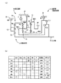
図1の(a) は、第1発明の一実施例である車両用自動変速機10の骨子図で、(b) は複数の変速段を成立させる際の係合要素および変速比を説明する作動表である。この車両用自動変速機10は、FF車両などの横置き用のもので、シングルピニオン型の第1遊星歯車装置12およびシングルピニオン型の第2遊星歯車装置14を主体として構成されている主変速部16と、ダブルピニオン型の第3遊星歯車装置18を主体として構成されている副変速部20とを有し、入力軸22の回転を変速して出力歯車24から出力する。入力軸22は入力部材に相当するもので、エンジン等の走行用駆動源によって回転駆動されるトルクコンバータのタービン軸などであり、出力歯車24は出力部材に相当するもので、差動歯車装置を介して左右の駆動輪を回転駆動する。なお、この車両用自動変速機10は中心線に対して略対称的に構成されており、図1(a) では中心線の下半分が省略されている。以下の各実施例についても同様である。
【0021】
上記副変速部20を構成している第3遊星歯車装置18のサンギヤS3は入力軸22に連結されて回転駆動され、キャリアC3は第3ブレーキB3を介して回転不能にケース26に固定され、リングギヤR3は中間出力部材として入力軸22に対して減速回転させられて出力する。また、主変速部16を構成している第1遊星歯車装置12および第2遊星歯車装置14は、一部が互いに連結されることによって4つの回転要素RM1〜RM4が構成されており、具体的には、第1遊星歯車装置12のサンギヤS1および第2遊星歯車装置14のサンギヤS2が互いに連結されて第1回転要素RM1が構成され、第1遊星歯車装置12のキャリアC1および第2遊星歯車装置14のキャリアC2が互いに連結されて第2回転要素RM2が構成され、第1遊星歯車装置12のリングギヤR1によって第3回転要素RM3が構成され、第2遊星歯車装置14のリングギヤR2によって第4回転要素RM4が構成されている。そして、第1回転要素RM1(サンギヤS1、S2)は第1ブレーキB1によって選択的にケース26に連結されて回転停止させられ、第2回転要素RM2(キャリアC1、C2)は第2ブレーキB2によって選択的にケース26に連結されて回転停止させられ、第1回転要素RM1(サンギヤS1、S2)は第1クラッチCL1を介して選択的に前記入力軸22に連結され、第2回転要素RM2(キャリアC1、C2)は第2クラッチCL2を介して選択的に入力軸22に連結され、第4回転要素RM4(リングギヤR2)は中間出力部材である前記第3遊星歯車装置18のリングギヤR3に一体的に連結され、第3回転要素RM3(リングギヤR1)は前記出力歯車24に一体的に連結されて回転を出力するようになっている。第1ブレーキB1〜第3ブレーキB3、第1クラッチCL1、第2クラッチCL2は、何れも油圧シリンダによって摩擦係合させられる多板式の油圧式摩擦係合装置である。なお、第2回転要素RM2とケース26との間には、第2回転要素RM2の正回転(入力軸22と同じ回転方向)を許容しつつ逆回転を阻止する一方向クラッチFが第2ブレーキB2と並列に設けられている。
【0022】
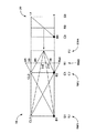
図2は、上記主変速部16および副変速部20の各回転要素の回転速度を直線で表すことができる共線図であり、下の横線が回転速度「0」で、上の横線が回転速度「1.0」すなわち入力軸22と同じ回転速度である。また、主変速部16の4本の縦線は、左端から右端へ向かって順番に第1回転要素RM1(サンギヤS1、S2)、第2回転要素RM2(キャリアC1、C2)、第3回転要素RM3(リングギヤR1)、第4回転要素RM4(リングギヤR2)を表しており、それ等の間隔は第1遊星歯車装置12のギヤ比(=サンギヤの歯数/リングギヤの歯数)ρ1および第2遊星歯車装置14のギヤ比ρ2に応じて定められる。副変速部20の各縦線は、左側から順番にキュリアC3、リングギヤR3、サンギヤS3を表しており、それ等の間隔は第3遊星歯車装置18のギヤ比ρ3に応じて定められる。そして、この共線図から明らかなように、第2ブレーキB2および第3ブレーキB3が係合させられて、第2回転要素RM2が回転停止させられるとともに第4回転要素RM4が副変速部20を介して減速回転させられると、出力歯車24に連結された第3回転要素RM3は「1st」で示す回転速度で回転させられ、最も大きい変速比の第1変速段「1st」が成立させられる。第1ブレーキB1および第3ブレーキB3が係合させられて、第1回転要素RM1が回転停止させられるとともに第4回転要素RM4が副変速部20を介して減速回転させられると、第3回転要素RM3は「2nd」で示す回転速度で回転させられ、第1変速段「1st」よりも変速比が小さい第2変速段「2nd」が成立させられる。第1クラッチCL1および第3ブレーキB3が係合させられて、第1回転要素RM1が入力軸22と一体回転させられるとともに第4回転要素RM4が副変速部20を介して減速回転させられると、第3回転要素RM3は「3rd」で示す回転速度で回転させられ、第2変速段「2nd」よりも変速比が小さい第3変速段「3rd」が成立させられる。第2クラッチCL2および第3ブレーキB3が係合させられて、第2回転要素RM2が入力軸22と一体回転させられるとともに第4回転要素RM4が副変速部20を介して減速回転させられると、第3回転要素RM3は「4th」で示す回転速度で回転させられ、第3変速段「3rd」よりも変速比が小さい第4変速段「4th」が成立させられる。第1クラッチCL1および第2クラッチCL2が係合させられて、主変速部16が入力軸22と一体回転させられると、第3回転要素RM3は「5th」で示す回転速度すなわち入力軸22と同じ回転速度で回転させられ、第4変速段「4th」よりも変速比が小さい第5変速段「5th」が成立させられる。この第5変速段「5th」の変速比は1である。第2クラッチCL2および第1ブレーキB1が係合させられて、第2回転要素RM2が入力軸22と一体回転させられるとともに第1回転要素RM1が回転停止させられると、第3回転要素RM3は「6th」で示す回転速度で回転させられ、第5変速段「5th」よりも変速比が小さい第6変速段「6th」が成立させられる。また、第1クラッチCL1および第2ブレーキB2が係合させられると、第1回転要素RM1が入力軸22と一体回転させられるとともに第2回転要素RM2が回転停止させられることにより、第3回転要素RM3は「Rev」で示す回転速度で逆回転させられ、後進変速段「Rev」が成立させられる。
【0023】
図1の(b) の作動表は、上記各変速段とクラッチCL1、CL2、ブレーキB1〜B3の作動状態との関係をまとめたもので、「○」は係合、「◎」はエンジンブレーキ時のみ係合を表している。第1変速段「1st」を成立させるブレーキB2には並列に一方向クラッチFが設けられているため、発進時(加速時)には必ずしもブレーキB2を係合させる必要は無いのである。また、各変速段の変速比は、第1遊星歯車装置12、第2遊星歯車装置14、および第3遊星歯車装置18の各ギヤ比ρ1、ρ2、ρ3によって適宜定められ、例えばρ1≒0.25、ρ2≒0.54、ρ3≒0.45とすれば、各遊星歯車装置12、14、16を比較的小型(小径)に維持しつつ図1(b) に示す変速比が得られ、ギヤ比ステップ(各変速段間の変速比の比)の値が略適切であるとともにトータルの変速比幅(=4.84/0.80)も6.05程度と大きく、全体として適切な変速比特性が得られる。
【0024】
このような車両用自動変速機10においては、3組の遊星歯車装置12、14、18と2つのクラッチCL1、CL2および3つのブレーキB1〜B3を用いて前進6段の多段変速が達成されるため、3つのクラッチおよび2つのブレーキを用いる場合に比較して、クラッチが少なくなった分だけ重量やコスト、軸長が低減される。
【0025】
また、前記第1遊星歯車装置12のサンギヤS1および第2遊星歯車装置14のサンギヤS2を一体に構成するとともに、第1遊星歯車装置12のキャリアC1および第2遊星歯車装置14のキャリアC2を一体に構成することにより、部品点数を削減したり軸長を更に短縮したりすることが可能である。
【0026】
次に、本発明の他の実施例を説明する。なお、以下の実施例において前記実施例と実質的に共通する部分には同一の符号を付して詳しい説明を省略する。
【0027】
図3の車両用自動変速機30は、第2発明の一実施例で、前記図1(a) に相当する骨子図であり、前記実施例に比較して主変速部32が相違する。主変速部32は、シングルピニオン型の第1遊星歯車装置34およびダブルピニオン型の第2遊星歯車装置36を主体として構成されているとともに、一部が互いに連結されることによって4つの回転要素RM1〜RM4が構成されている。具体的には、第1遊星歯車装置34のサンギヤS1によって第1回転要素RM1が構成され、第1遊星歯車装置34のキャリアC1および第2遊星歯車装置36のキャリアC2が互いに連結されて第2回転要素RM2が構成され、第1遊星歯車装置34のリングギヤR1および第2遊星歯車装置36のリングギヤR2が互いに連結されて第3回転要素RM3が構成され、第2遊星歯車装置36のサンギヤS2によって第4回転要素RM4が構成されている。なお、上記キャリアC1およびC2は共通の部材にて構成されているとともに、リングギヤR1およびR2は共通の部材にて構成されており、第1遊星歯車装置34のピニオンギヤが第2遊星歯車装置36の第2ピニオンギヤを兼ねているラビニヨ型の遊星歯車列とされている。
【0028】
そして、上記各回転要素RM1〜RM4は、直接或いはブレーキB1〜B3やクラッチCL1、CL2、一方向クラッチFを介して選択的に所定の部材に連結されて前記図1(a) と同じ連結構造とされており、図2と同様の共線図が得られるとともに、図1(b) に示す作動表に従って第1変速段「1st」〜第6変速段「6th」の前進6段および後進変速段「Rev」が成立させられるようになっている。また、各変速段の変速比は、第1遊星歯車装置34、第2遊星歯車装置36、および第3遊星歯車装置18の各ギヤ比ρ1、ρ2、ρ3によって適宜定められ、例えばρ1≒0.25、ρ2≒0.46、ρ3≒0.45とすれば、図1(b) と同じ変速比が得られる。
【0029】
このような車両用自動変速機30においても、2つのクラッチCL1、CL2および3つのブレーキB1〜B3を用いて前進6段の多段変速が達成されるため、前記実施例と同様に重量やコスト、軸長が低減される。また、本実施例ではシングルピニオン型の第1遊星歯車装置34およびダブルピニオン型の第2遊星歯車装置36がラビニヨ型の遊星歯車列とされているため、部品点数や軸長が一層低減される。
【0039】
以上、本発明の実施例を図面に基づいて詳細に説明したが、これ等はあくまでも一実施形態であり、本発明は当業者の知識に基づいて種々の変更,改良を加えた態様で実施することができる。
【図面の簡単な説明】
【図1】本発明の一実施例である車両用自動変速機を説明する図で、(a) は骨子図、(b) は各変速段を成立させるための作動表である。
【図2】図1の実施例の共線図である。
【図3】本発明の他の実施例を示す図で、図1(a) に相当する骨子図である。
【符号の説明】
10、30:車両用自動変速機(自動変速機) 12、34:第1遊星歯車装置
14、36:第2遊星歯車装置 16、32:主変速部 18:第3遊星歯車装置
20:副変速部 22:入力軸(入力部材) 24:出力歯車(出力部材) RM1:第1回転要素 RM2:第2回転要素 RM3:第3回転要素 RM4:第4回転要素 CL1:第1クラッチ CL2:第2クラッチ B1:第1ブレーキ
B2:第2ブレーキ B3:第3ブレーキ[0001]
BACKGROUND OF THE INVENTION
The present invention relates to an automatic transmission, and more particularly to an automatic transmission capable of multi-stage shifting with a small number of clutches.
[0002]
[Prior art]
As an automatic transmission for a vehicle, one using a plurality of planetary gear devices, clutches and brakes is often used. An example of the automatic transmission described in Japanese Patent Application Laid-Open No. 2000-199549 is that six forward gears can be shifted using three sets of planetary gear units, three clutches, and two brakes.
[0003]
[Problems to be solved by the invention]
However, since the clutch rotates, a drum, a seal ring, a centrifugal hydraulic pressure canceling mechanism for the cylinder chamber, etc. are required, which is heavier and more expensive than a brake. It will be disadvantageous.
[0004]
The present invention has been made against the background of the above circumstances, and the object of the present invention is to enable 6-speed forward multi-speed shift with two clutches.
[0005]
[Means for Solving the Problems]
In order to achieve such an object, according to a first aspect of the present invention, in an automatic transmission, (a) any one of a sun gear, a carrier, and a ring gear of a third planetary gear device is connected to an input member and driven to rotate. A sub-transmission unit that is selectively stopped by the third brake, and one of which is decelerated and rotated with respect to the input member as an intermediate output member, and (b) a single pinion type first planetary gear device and a single A pinion-type second planetary gear device , the sun gear of the first planetary gear device and the sun gear of the second planetary gear device are connected to each other to form a first rotating element, and the carrier of the first planetary gear device and the second planetary gear device; The carrier of the planetary gear device is connected to each other to form a second rotating element, and the third rotating element is constituted by the ring gear of the first planetary gear device. The fourth rotating element is constituted by the ring gear, and the first rotating element, the second rotating element, the third rotating element, and the fourth rotating element represent the rotational speeds of the four rotating elements in a straight line. selection collinear diagram odor converting mechanism located order from one end to the other, by the first rotating element is stopped selectively rotated by a first brake, the second rotary element and the second brake can The first rotation element is selectively connected to the input member via a first clutch, the second rotation element is selectively connected to the input member via a second clutch, The four rotation elements are integrally connected to the intermediate output member, and the third rotation element is integrally connected to the output member, and includes a main transmission unit that outputs rotation, (c) the second rotation element The brake and the third brake The first gear stage having the largest gear ratio is established by being engaged, and the second gear ratio having a gear ratio smaller than that of the first gear stage is established by engaging the first brake and the third brake. A first gear is established, and the first clutch and the third brake are engaged to establish a third gear that is smaller in speed ratio than the second gear, and the second clutch and the third When the brake is engaged, a fourth shift stage having a gear ratio smaller than that of the third shift stage is established, and when the first clutch and the second clutch are engaged, the fourth shift stage is established. The fifth gear stage having a smaller gear ratio is established, and the second clutch and the first brake are engaged, so that the gear ratio is higher than that of the fifth gear stage. Sixth shift stage is characterized in that is established small.
The gear ratio is the ratio of the rotational speed of the input member to the rotational speed of the output member (= input member rotational speed / output member rotational speed).
[0006]
The second invention is an automatic transmission, wherein (a) any one of a sun gear, a carrier, and a ring gear of a third planetary gear device is connected to an input member to be driven to rotate, and one is selectively rotated by a third brake. A sub-transmission unit which is stopped and one of which is rotated and decelerated with respect to the input member as an intermediate output member, and (b) a single-pinion type first planetary gear device and a double-pinion type second planetary gear device. The first planetary gear device has a sun gear to form a first rotating element, and the first planetary gear device carrier and the second planetary gear device carrier are connected to each other to form a second rotating element. The ring gear of the planetary gear device and the ring gear of the second planetary gear device are connected to each other to constitute a third rotating element, and the fourth rotating element is constituted by the sun gear of the second planetary gear device. The first rotation element, the second rotation element, the third rotation element, and the fourth rotation element are configured on a collinear chart in which the rotation speeds of the four rotation elements can be represented by straight lines. The first rotating element is selectively stopped by the first brake, the second rotating element is selectively stopped by the second brake, and sequentially positioned from one end to the other end. The rotating element is selectively connected to the input member via a first clutch, the second rotating element is selectively connected to the input member via a second clutch, and the fourth rotating element is connected to the intermediate output member. (C) the second brake and the third brake are engaged with each other, and the third rotation element includes a main transmission unit that is integrally connected to the output member and outputs rotation. By being allowed to A first gear stage having a large gear ratio is established, and a second gear stage having a smaller gear ratio than the first gear stage is established by engaging the first brake and the third brake, By engaging the first clutch and the third brake, a third shift stage having a smaller gear ratio than the second shift stage is established, and the second clutch and the third brake are engaged. To establish a fourth gear stage having a gear ratio smaller than that of the third gear stage, and a fifth gear ratio having a gear ratio smaller than that of the fourth gear stage is established by engaging the first clutch and the second clutch. A sixth shift stage having a smaller gear ratio than the fifth shift stage is established by establishing the shift stage and engaging the second clutch and the first brake. It is characterized by that.
[0008]
【The invention's effect】
In the automatic transmissions according to the first and second aspects of the present invention, since the multi-speed shift of six forward speeds is achieved using the three planetary gear units, the two clutches, and the three brakes, the three clutches and Compared to the case where two brakes are used, the weight, cost, and shaft length can be reduced by the amount of clutch reduction.
[0009]
Further, while using relatively small (small diameter) three planetary gear devices, the gear ratios of the first to sixth gears can be appropriately set by appropriately determining the gear ratio ρ thereof. . In the second invention, since the carriers and the ring gears of the single-pinion type first planetary gear device and the double-pinion type second planetary gear device are connected to each other, they are shared to form a Ravigneaux type. As a result, the number of parts and the axial length can be further reduced.
[0010]
DETAILED DESCRIPTION OF THE INVENTION
The present invention is suitably applied to an automatic transmission for a vehicle. For example, rotation is input from a traveling drive source such as an internal combustion engine through a fluid coupling such as a torque converter, and a gear is output at a predetermined speed ratio. It is transmitted from the output member such as the shaft to the left and right drive wheels via the differential gear device, but can also be applied to automatic transmissions other than those for vehicles. The input member is, for example, a turbine shaft of a torque converter.
[0011]
The mounting position of the automatic transmission with respect to the vehicle is such that the axis of the automatic transmission is in the longitudinal direction of the vehicle even in a horizontal type such as an FF (front engine / front drive) vehicle in which the axis of the automatic transmission is in the vehicle width direction. A vertical installation type such as an FR (front engine / rear drive) vehicle may be used.
[0012]
The automatic transmission may be one that automatically switches the gear position according to the operating state such as the accelerator operation amount or the vehicle speed, but may be one that switches the gear position according to the driver's switch operation (up / down operation or the like). Although the automatic transmission according to the present invention can perform multi-speed shifting with six forward speeds, the reverse speed can be established by engaging the first clutch and the second brake.
[0013]
As the third planetary gear device constituting the auxiliary transmission unit, either a double pinion type or a single pinion type can be adopted. However, in setting the transmission ratio in a geometric series, the transmission of the auxiliary transmission unit When the ratio is about 0.5, a double pinion type planetary gear device is preferably used to reduce the diameter. That is, the sun gear of the double-pinion type planetary gear device is connected to the input member to be driven to rotate, the carrier is selectively stopped by the third brake, and the ring gear serves as an intermediate output member to rotate at a reduced speed relative to the input member. Or the carrier is connected to the input member and driven to rotate, the sun gear is selectively stopped by the third brake, and the ring gear serves as an intermediate output member with respect to the input member. It is configured to be rotated at reduced speed and output.
[0014]
As the first brake to the third brake, the first clutch, and the second clutch, hydraulic friction engagement devices such as a multi-plate type, a single plate type, and a belt type that are frictionally engaged by a hydraulic cylinder are preferably used. Other types of engagement devices, such as a formula, can also be employed. In order to facilitate the speed change control, a one-way clutch may be provided in parallel with the second brake. If the engine brake is not required, a one-way clutch may be provided instead of the second brake. The one-way clutch has the same function as the brake in that it stops rotating. It is also possible to provide a brake and a one-way clutch connected in series in parallel with the first brake.
[0015]
In the second invention, the carriers of the first planetary gear device and the second planetary gear device and the ring gears can be shared to form a Ravigneaux type, but they are separately configured and integrally connected by a connecting member or the like. May be.
[0019]
The positional relationship between the main transmission unit and the sub-transmission unit and the positional relationship between the first planetary gear device and the second planetary gear device of the main transmission unit are not particularly limited. Various modes are possible, such as disposing the first planetary gear device between the two planetary gear devices.
[0020]
Hereinafter, embodiments of the present invention will be described in detail with reference to the drawings.
(A) of FIG. 1 is a skeleton view of a vehicular automatic transmission 10 which is an embodiment of the light first shot, the (b) engagement elements and the speed change ratio at the time of establishing a plurality of gear positions Description It is an operation table. The automatic transmission 10 for a vehicle is for horizontal installation of an FF vehicle or the like, and is a main transmission mainly composed of a single pinion type first
[0021]
The sun gear S3 of the third
[0022]
FIG. 2 is a collinear diagram in which the rotational speeds of the rotary elements of the
[0023]
The operation table of FIG. 1 (b) summarizes the relationship between the above-mentioned shift speeds and the operation states of the clutches CL1, CL2 and the brakes B1 to B3, where “◯” indicates engagement and “◎” indicates engine brake. Only the time represents engagement. Since the one-way clutch F is provided in parallel with the brake B2 that establishes the first shift stage “1st”, it is not always necessary to engage the brake B2 at the time of start (acceleration). Further, the gear ratio of each gear stage is appropriately determined by the gear ratios ρ1, ρ2, and ρ3 of the first
[0024]
In such an automatic transmission 10 for a vehicle, a multi-speed shift with six forward speeds is achieved by using three sets of
[0025]
The sun gear S1 of the first
[0026]
Next, another embodiment of the present invention will be described. In the following embodiments, parts that are substantially the same as those in the above embodiments are denoted by the same reference numerals, and detailed description thereof is omitted.
[0027]
An
[0028]
Each of the rotating elements RM1 to RM4 is connected to a predetermined member directly or via the brakes B1 to B3, the clutches CL1 and CL2, and the one-way clutch F, and has the same connection structure as that shown in FIG. The collinear chart similar to that of FIG. 2 is obtained, and the six forward speeds and the reverse speeds of the first gear stage “1st” to the sixth gear stage “6th” are obtained according to the operation table shown in FIG. The stage “Rev” is established. Further, the gear ratio of each gear stage is appropriately determined by the gear ratios ρ1, ρ2, and ρ3 of the first
[0029]
In such a vehicular
[0039]
As mentioned above, although the Example of this invention was described in detail based on drawing, these are one embodiment to the last, and this invention is implemented in the aspect which added the various change and improvement based on the knowledge of those skilled in the art. be able to.
[Brief description of the drawings]
1A and 1B are diagrams for explaining an automatic transmission for a vehicle according to an embodiment of the present invention, in which FIG. 1A is a skeleton diagram and FIG. 1B is an operation table for establishing each gear stage;
FIG. 2 is a collinear diagram of the embodiment of FIG.
FIG. 3 is a diagram showing another embodiment of the present invention, and is a skeleton diagram corresponding to FIG.
[Explanation of symbols]
DESCRIPTION OF SYMBOLS 10, 30 : Automatic transmission for vehicles (automatic transmission) 12, 3, 4: 1st
Claims (2)
シングルピニオン型の第1遊星歯車装置およびシングルピニオン型の第2遊星歯車装置を有し、該第1遊星歯車装置のサンギヤおよび該第2遊星歯車装置のサンギヤが互いに連結されて第1回転要素が構成され、該第1遊星歯車装置のキャリアおよび該第2遊星歯車装置のキャリアが互いに連結されて第2回転要素が構成され、該第1遊星歯車装置のリングギヤによって第3回転要素が構成され、該第2遊星歯車装置のリングギヤによって第4回転要素が構成されており、それ等の第1回転要素、第2回転要素、第3回転要素、および第4回転要素は、該4つの回転要素の回転速度を直線で表すことができる共線図上において一端から他端へ向かって順番に位置するとともに、該第1回転要素は第1ブレーキによって選択的に回転停止させられ、該第2回転要素は第2ブレーキによって選択的に回転停止させられ、該第1回転要素は第1クラッチを介して選択的に前記入力部材に連結され、該第2回転要素は第2クラッチを介して選択的に前記入力部材に連結され、該第4回転要素は前記中間出力部材に一体的に連結され、該第3回転要素は出力部材に一体的に連結されて出力する主変速部と、
を備えている一方、
前記第2ブレーキおよび前記第3ブレーキが係合させられることによって最も大きい変速比の第1変速段が成立させられ、前記第1ブレーキおよび前記第3ブレーキが係合させられることによって前記第1変速段よりも変速比が小さい第2変速段が成立させられ、前記第1クラッチおよび前記第3ブレーキが係合させられることによって前記第2変速段よりも変速比が小さい第3変速段が成立させられ、前記第2クラッチおよび前記第3ブレーキが係合させられることによって前記第3変速段よりも変速比が小さい第4変速段が成立させられ、前記第1クラッチおよび前記第2クラッチが係合させられることによって前記第4変速段よりも変速比が小さい第5変速段が成立させられ、前記第2クラッチおよび前記第1ブレーキが係合させられることによって前記第5変速段よりも変速比が小さい第6変速段が成立させられる
ことを特徴とする自動変速機。Any one of the sun gear, the carrier, and the ring gear of the third planetary gear device is connected to the input member for rotational driving, one is selectively stopped by the third brake, and one is the input member as an intermediate output member. A sub-transmission unit that is rotated at a reduced speed with respect to the output, and
A single pinion type first planetary gear unit and a single pinion type second planetary gear unit , wherein the sun gear of the first planetary gear unit and the sun gear of the second planetary gear unit are coupled to each other to Configured, the carrier of the first planetary gear device and the carrier of the second planetary gear device are connected to each other to form a second rotating element, and the ring gear of the first planetary gear device forms a third rotating element, A fourth rotating element is configured by the ring gear of the second planetary gear device, and the first rotating element, the second rotating element, the third rotating element, and the fourth rotating element are the four rotating elements. the rotational speed Te collinear diagram smell can be represented by a straight line with located order from one end to the other, said first rotating element stops selectively rotated by a first brake et al The second rotation element is selectively stopped by a second brake, the first rotation element is selectively connected to the input member via a first clutch, and the second rotation element is a second clutch. A main transmission unit that is selectively connected to the input member via the input member, the fourth rotating element is integrally connected to the intermediate output member, and the third rotating element is integrally connected to the output member for output. When,
While
The first shift stage having the largest speed ratio is established by engaging the second brake and the third brake, and the first shift is performed by engaging the first brake and the third brake. A second gear stage having a gear ratio smaller than that of the gear stage is established, and the third gear stage having a gear ratio smaller than that of the second gear stage is established by engaging the first clutch and the third brake. When the second clutch and the third brake are engaged, a fourth shift stage having a gear ratio smaller than that of the third shift stage is established, and the first clutch and the second clutch are engaged. As a result, a fifth shift stage having a gear ratio smaller than that of the fourth shift stage is established, and the second clutch and the first brake are engaged. Automatic transmission, wherein a sixth gear position gear ratio than the fifth gear position is smaller is established by.
シングルピニオン型の第1遊星歯車装置およびダブルピニオン型の第2遊星歯車装置を有し、該第1遊星歯車装置のサンギヤによって第1回転要素が構成され、該第1遊星歯車装置のキャリアおよび該第2遊星歯車装置のキャリアが互いに連結されて第2回転要素が構成され、該第1遊星歯車装置のリングギヤおよび該第2遊星歯車装置のリングギヤが互いに連結されて第3回転要素が構成され、該第2遊星歯車装置のサンギヤによって第4回転要素が構成されており、それ等の第1回転要素、第2回転要素、第3回転要素、および第4回転要素は、該4つの回転要素の回転速度を直線で表すことができる共線図上において一端から他端へ向かって順番に位置するとともに、該第1回転要素は第1ブレーキによって選択的に回転停止させられ、該第2回転要素は第2ブレーキによって選択的に回転停止させられ、該第1回転要素は第1クラッチを介して選択的に前記入力部材に連結され、該第2回転要素は第2クラッチを介して選択的に前記入力部材に連結され、該第4回転要素は前記中間出力部材に一体的に連結され、該第3回転要素は出力部材に一体的に連結されて出力する主変速部と、A first pinion-type first planetary gear device and a double-pinion-type second planetary gear device, wherein a first rotating element is constituted by the sun gear of the first planetary gear device, the carrier of the first planetary gear device, and the A carrier of the second planetary gear device is connected to each other to form a second rotating element, and a ring gear of the first planetary gear device and a ring gear of the second planetary gear device are connected to each other to form a third rotating element, A fourth rotating element is constituted by the sun gear of the second planetary gear device, and the first rotating element, the second rotating element, the third rotating element, and the fourth rotating element are the four rotating elements. The rotation speed is positioned in order from one end to the other end on a nomographic chart in which the rotation speed can be expressed by a straight line, and the first rotation element is selectively stopped by the first brake. The second rotating element is selectively stopped by a second brake, the first rotating element is selectively connected to the input member via a first clutch, and the second rotating element engages the second clutch. A main transmission unit selectively connected to the input member, the fourth rotating element integrally connected to the intermediate output member, and the third rotating element integrally connected to the output member for output. ,
を備えている一方、While
前記第2ブレーキおよび前記第3ブレーキが係合させられることによって最も大きい変速比の第1変速段が成立させられ、前記第1ブレーキおよび前記第3ブレーキが係合させWhen the second brake and the third brake are engaged, the first gear stage having the largest gear ratio is established, and the first brake and the third brake are engaged. られることによって前記第1変速段よりも変速比が小さい第2変速段が成立させられ、前記第1クラッチおよび前記第3ブレーキが係合させられることによって前記第2変速段よりも変速比が小さい第3変速段が成立させられ、前記第2クラッチおよび前記第3ブレーキが係合させられることによって前記第3変速段よりも変速比が小さい第4変速段が成立させられ、前記第1クラッチおよび前記第2クラッチが係合させられることによって前記第4変速段よりも変速比が小さい第5変速段が成立させられ、前記第2クラッチおよび前記第1ブレーキが係合させられることによって前記第5変速段よりも変速比が小さい第6変速段が成立させられるTo establish a second gear stage having a gear ratio smaller than that of the first gear stage, and by engaging the first clutch and the third brake, the gear ratio is smaller than that of the second gear stage. A third shift stage is established, and the second clutch and the third brake are engaged to establish a fourth shift stage having a gear ratio smaller than that of the third shift stage, and the first clutch and When the second clutch is engaged, a fifth shift stage having a gear ratio smaller than that of the fourth shift stage is established, and when the second clutch and the first brake are engaged, the fifth shift stage is established. A sixth shift speed having a smaller gear ratio than the shift speed is established.
ことを特徴とする自動変速機。An automatic transmission characterized by that.
Priority Applications (4)
| Application Number | Priority Date | Filing Date | Title |
|---|---|---|---|
| JP2001332179A JP3630132B2 (en) | 2001-10-30 | 2001-10-30 | Automatic transmission |
| DE10250371A DE10250371A1 (en) | 2001-10-30 | 2002-10-29 | automatic transmission |
| US10/281,958 US7094174B2 (en) | 2001-10-30 | 2002-10-29 | Automatic transmission |
| US10/986,120 US7037233B2 (en) | 2001-10-30 | 2004-11-12 | Automatic transmission |
Applications Claiming Priority (1)
| Application Number | Priority Date | Filing Date | Title |
|---|---|---|---|
| JP2001332179A JP3630132B2 (en) | 2001-10-30 | 2001-10-30 | Automatic transmission |
Publications (2)
| Publication Number | Publication Date |
|---|---|
| JP2003130153A JP2003130153A (en) | 2003-05-08 |
| JP3630132B2 true JP3630132B2 (en) | 2005-03-16 |
Family
ID=19147633
Family Applications (1)
| Application Number | Title | Priority Date | Filing Date |
|---|---|---|---|
| JP2001332179A Expired - Fee Related JP3630132B2 (en) | 2001-10-30 | 2001-10-30 | Automatic transmission |
Country Status (3)
| Country | Link |
|---|---|
| US (2) | US7094174B2 (en) |
| JP (1) | JP3630132B2 (en) |
| DE (1) | DE10250371A1 (en) |
Families Citing this family (12)
| Publication number | Priority date | Publication date | Assignee | Title |
|---|---|---|---|---|
| KR100610791B1 (en) | 2004-09-01 | 2006-08-09 | 현대자동차주식회사 | A six-speed powertrain of an automatic transmission |
| KR100634610B1 (en) * | 2004-12-22 | 2006-10-16 | 현대자동차주식회사 | A 6th-speed power train of an automatic transmission |
| KR100634616B1 (en) * | 2004-12-22 | 2006-10-16 | 현대자동차주식회사 | A 6th-speed power train of an automatic transmission |
| JP4604951B2 (en) * | 2005-10-07 | 2011-01-05 | トヨタ自動車株式会社 | Control device for automatic transmission |
| WO2012070110A1 (en) * | 2010-11-22 | 2012-05-31 | トヨタ自動車株式会社 | Control device for vehicle power-transmission device |
| DE102012207017A1 (en) * | 2012-04-27 | 2013-10-31 | Zf Friedrichshafen Ag | Multi-speed transmission |
| CN102788121A (en) * | 2012-08-31 | 2012-11-21 | 哈尔滨东安汽车发动机制造有限公司 | Planet structure of 6-gear automatic gearbox |
| KR101755476B1 (en) * | 2015-09-14 | 2017-07-10 | 현대자동차 주식회사 | Planetary gear train of automatic transmission for vehicles |
| DE102016211270A1 (en) | 2016-06-23 | 2017-12-28 | Zf Friedrichshafen Ag | A planetary gear set system for a motor vehicle transmission, transmission for a motor vehicle with such a planetary gear set system, and drive train for a motor vehicle |
| DE102016212226A1 (en) | 2016-07-05 | 2018-01-11 | Zf Friedrichshafen Ag | Transmission for a motor vehicle |
| DE102016212366A1 (en) | 2016-07-07 | 2018-01-11 | Zf Friedrichshafen Ag | Transmission for a motor vehicle |
| DE102018000187B4 (en) * | 2018-02-08 | 2022-10-06 | Mercedes-Benz Group AG | Transmission device, in particular for a motor vehicle |
Family Cites Families (22)
| Publication number | Priority date | Publication date | Assignee | Title |
|---|---|---|---|---|
| JP2679115B2 (en) | 1988-06-16 | 1997-11-19 | トヨタ自動車株式会社 | Planetary gear type transmission for vehicles |
| JPH02107852A (en) | 1988-10-14 | 1990-04-19 | Toyota Motor Corp | Planetary gear type transmission for vehicle |
| JPH02118247A (en) | 1988-10-27 | 1990-05-02 | Toyota Motor Corp | Gear speed change gear |
| FR2656055B1 (en) | 1989-12-18 | 1994-04-29 | Lepelletier Pierre | MULTI-SPEED AUTOMATIC TRANSMISSION FOR MOTOR VEHICLE. |
| JP2956173B2 (en) | 1990-09-05 | 1999-10-04 | 日産自動車株式会社 | Planetary gear train of automatic transmission |
| JP2939316B2 (en) | 1990-09-28 | 1999-08-25 | 本田技研工業株式会社 | Planetary gear transmission |
| JPH0526310A (en) * | 1991-07-18 | 1993-02-02 | Nissan Motor Co Ltd | Epicyclic gear transmission mechanism |
| JP3446345B2 (en) | 1994-10-03 | 2003-09-16 | トヨタ自動車株式会社 | Gear transmission |
| JP3710180B2 (en) | 1995-10-31 | 2005-10-26 | ジヤトコ株式会社 | Gear transmission for automatic transmission |
| JP4096468B2 (en) | 1998-10-30 | 2008-06-04 | アイシン・エィ・ダブリュ株式会社 | Automatic transmission for vehicles |
| JP4228452B2 (en) | 1999-02-22 | 2009-02-25 | アイシン精機株式会社 | Transmission |
| DE19910299C1 (en) | 1999-03-10 | 2001-04-19 | Daimler Chrysler Ag | Planetary gear change transmission with three partial transmissions |
| JP2000274499A (en) | 1999-03-19 | 2000-10-03 | Aisin Seiki Co Ltd | Transmission |
| US6503170B1 (en) * | 1999-08-20 | 2003-01-07 | Toyota Jidosha Kabushiki Kaisha | Control device for an automatic transmission |
| JP4244461B2 (en) | 1999-09-09 | 2009-03-25 | アイシン・エィ・ダブリュ株式会社 | Automatic transmission for vehicles |
| JP3777929B2 (en) | 1999-12-24 | 2006-05-24 | アイシン精機株式会社 | Transmission |
| JP3463274B2 (en) * | 2000-01-11 | 2003-11-05 | アイシン・エィ・ダブリュ株式会社 | Automatic transmission for vehicles |
| JP2001199549A (en) | 2000-01-17 | 2001-07-24 | Mitsubishi Heavy Ind Ltd | Picking device for unloader |
| US6422969B1 (en) * | 2000-08-14 | 2002-07-23 | General Motors Corporation | Powertrain with a six speed planetary transmission having three planetary gear sets |
| US6422959B1 (en) * | 2000-10-31 | 2002-07-23 | Kevin Hsu | Twin flying discs |
| US6422968B1 (en) * | 2001-01-22 | 2002-07-23 | General Motors Corporation | Compact six speed power transmission |
| JP4438247B2 (en) * | 2001-03-29 | 2010-03-24 | アイシン・エィ・ダブリュ株式会社 | Automatic transmission for vehicles |
-
2001
- 2001-10-30 JP JP2001332179A patent/JP3630132B2/en not_active Expired - Fee Related
-
2002
- 2002-10-29 US US10/281,958 patent/US7094174B2/en not_active Expired - Fee Related
- 2002-10-29 DE DE10250371A patent/DE10250371A1/en not_active Ceased
-
2004
- 2004-11-12 US US10/986,120 patent/US7037233B2/en not_active Expired - Fee Related
Also Published As
| Publication number | Publication date |
|---|---|
| DE10250371A1 (en) | 2003-07-31 |
| US7094174B2 (en) | 2006-08-22 |
| US20030083172A1 (en) | 2003-05-01 |
| US7037233B2 (en) | 2006-05-02 |
| JP2003130153A (en) | 2003-05-08 |
| US20050090363A1 (en) | 2005-04-28 |
Similar Documents
| Publication | Publication Date | Title |
|---|---|---|
| JP3763296B2 (en) | Automatic transmission | |
| JP3736481B2 (en) | Automatic transmission | |
| JP4148061B2 (en) | Multi-speed transmission | |
| US6887178B2 (en) | Automatic transmission | |
| JP4380291B2 (en) | Planetary gear type multi-stage transmission for vehicles | |
| JP4127162B2 (en) | Multi-speed transmission | |
| KR100644482B1 (en) | A six-speed powertrain of an automatic transmissionfor a vehicle | |
| JP2001182785A (en) | Transmission | |
| JP5293785B2 (en) | Multi-speed transmission | |
| JP4380572B2 (en) | Multi-speed transmission | |
| JP2005106260A (en) | Planetary gear type multi-stage transmission for vehicle | |
| JP3630132B2 (en) | Automatic transmission | |
| US7429228B2 (en) | Multi-speed automatic transmission for motor vehicle | |
| JP4269832B2 (en) | Multi-speed transmission | |
| JP2009063139A (en) | Multistage shift planetary gear train | |
| JP2007032593A (en) | Multi-stage transmission | |
| JP2001182786A (en) | Transmission | |
| JP3903385B2 (en) | 6-speed powertrain for vehicle automatic transmission | |
| JP2005048909A (en) | Multi-stage transmission | |
| JP4061932B2 (en) | Automatic transmission | |
| JP4839686B2 (en) | Multi-speed transmission | |
| US6875149B2 (en) | Automatic transmission | |
| JP4055675B2 (en) | Automatic transmission | |
| JP4124057B2 (en) | Automatic transmission | |
| JP4269834B2 (en) | Multi-speed transmission |
Legal Events
| Date | Code | Title | Description |
|---|---|---|---|
| A977 | Report on retrieval |
Free format text: JAPANESE INTERMEDIATE CODE: A971007 Effective date: 20040722 |
|
| A131 | Notification of reasons for refusal |
Free format text: JAPANESE INTERMEDIATE CODE: A131 Effective date: 20040817 |
|
| A521 | Written amendment |
Free format text: JAPANESE INTERMEDIATE CODE: A523 Effective date: 20041004 |
|
| TRDD | Decision of grant or rejection written | ||
| A01 | Written decision to grant a patent or to grant a registration (utility model) |
Free format text: JAPANESE INTERMEDIATE CODE: A01 Effective date: 20041124 |
|
| A61 | First payment of annual fees (during grant procedure) |
Free format text: JAPANESE INTERMEDIATE CODE: A61 Effective date: 20041207 |
|
| R150 | Certificate of patent or registration of utility model |
Free format text: JAPANESE INTERMEDIATE CODE: R150 |
|
| FPAY | Renewal fee payment (event date is renewal date of database) |
Free format text: PAYMENT UNTIL: 20081224 Year of fee payment: 4 |
|
| FPAY | Renewal fee payment (event date is renewal date of database) |
Free format text: PAYMENT UNTIL: 20081224 Year of fee payment: 4 |
|
| FPAY | Renewal fee payment (event date is renewal date of database) |
Free format text: PAYMENT UNTIL: 20091224 Year of fee payment: 5 |
|
| FPAY | Renewal fee payment (event date is renewal date of database) |
Free format text: PAYMENT UNTIL: 20101224 Year of fee payment: 6 |
|
| LAPS | Cancellation because of no payment of annual fees |