JP3763296B2 - Automatic transmission - Google Patents
Automatic transmission Download PDFInfo
- Publication number
- JP3763296B2 JP3763296B2 JP2002321851A JP2002321851A JP3763296B2 JP 3763296 B2 JP3763296 B2 JP 3763296B2 JP 2002321851 A JP2002321851 A JP 2002321851A JP 2002321851 A JP2002321851 A JP 2002321851A JP 3763296 B2 JP3763296 B2 JP 3763296B2
- Authority
- JP
- Japan
- Prior art keywords
- gear
- rotating element
- brake
- planetary gear
- clutch
- Prior art date
- Legal status (The legal status is an assumption and is not a legal conclusion. Google has not performed a legal analysis and makes no representation as to the accuracy of the status listed.)
- Expired - Fee Related
Links
Images


Classifications
-
- F—MECHANICAL ENGINEERING; LIGHTING; HEATING; WEAPONS; BLASTING
- F16—ENGINEERING ELEMENTS AND UNITS; GENERAL MEASURES FOR PRODUCING AND MAINTAINING EFFECTIVE FUNCTIONING OF MACHINES OR INSTALLATIONS; THERMAL INSULATION IN GENERAL
- F16H—GEARING
- F16H3/00—Toothed gearings for conveying rotary motion with variable gear ratio or for reversing rotary motion
- F16H3/44—Toothed gearings for conveying rotary motion with variable gear ratio or for reversing rotary motion using gears having orbital motion
- F16H3/62—Gearings having three or more central gears
- F16H3/66—Gearings having three or more central gears composed of a number of gear trains without drive passing from one train to another
- F16H3/666—Gearings having three or more central gears composed of a number of gear trains without drive passing from one train to another with compound planetary gear units, e.g. two intermeshing orbital gears
-
- F—MECHANICAL ENGINEERING; LIGHTING; HEATING; WEAPONS; BLASTING
- F16—ENGINEERING ELEMENTS AND UNITS; GENERAL MEASURES FOR PRODUCING AND MAINTAINING EFFECTIVE FUNCTIONING OF MACHINES OR INSTALLATIONS; THERMAL INSULATION IN GENERAL
- F16H—GEARING
- F16H3/00—Toothed gearings for conveying rotary motion with variable gear ratio or for reversing rotary motion
- F16H3/44—Toothed gearings for conveying rotary motion with variable gear ratio or for reversing rotary motion using gears having orbital motion
- F16H3/62—Gearings having three or more central gears
- F16H3/66—Gearings having three or more central gears composed of a number of gear trains without drive passing from one train to another
- F16H3/663—Gearings having three or more central gears composed of a number of gear trains without drive passing from one train to another with conveying rotary motion between axially spaced orbital gears, e.g. RAVIGNEAUX
-
- F—MECHANICAL ENGINEERING; LIGHTING; HEATING; WEAPONS; BLASTING
- F16—ENGINEERING ELEMENTS AND UNITS; GENERAL MEASURES FOR PRODUCING AND MAINTAINING EFFECTIVE FUNCTIONING OF MACHINES OR INSTALLATIONS; THERMAL INSULATION IN GENERAL
- F16H—GEARING
- F16H2200/00—Transmissions for multiple ratios
- F16H2200/003—Transmissions for multiple ratios characterised by the number of forward speeds
- F16H2200/0052—Transmissions for multiple ratios characterised by the number of forward speeds the gear ratios comprising six forward speeds
-
- F—MECHANICAL ENGINEERING; LIGHTING; HEATING; WEAPONS; BLASTING
- F16—ENGINEERING ELEMENTS AND UNITS; GENERAL MEASURES FOR PRODUCING AND MAINTAINING EFFECTIVE FUNCTIONING OF MACHINES OR INSTALLATIONS; THERMAL INSULATION IN GENERAL
- F16H—GEARING
- F16H2200/00—Transmissions for multiple ratios
- F16H2200/20—Transmissions using gears with orbital motion
- F16H2200/2002—Transmissions using gears with orbital motion characterised by the number of sets of orbital gears
- F16H2200/2007—Transmissions using gears with orbital motion characterised by the number of sets of orbital gears with two sets of orbital gears
-
- F—MECHANICAL ENGINEERING; LIGHTING; HEATING; WEAPONS; BLASTING
- F16—ENGINEERING ELEMENTS AND UNITS; GENERAL MEASURES FOR PRODUCING AND MAINTAINING EFFECTIVE FUNCTIONING OF MACHINES OR INSTALLATIONS; THERMAL INSULATION IN GENERAL
- F16H—GEARING
- F16H2200/00—Transmissions for multiple ratios
- F16H2200/20—Transmissions using gears with orbital motion
- F16H2200/2002—Transmissions using gears with orbital motion characterised by the number of sets of orbital gears
- F16H2200/201—Transmissions using gears with orbital motion characterised by the number of sets of orbital gears with three sets of orbital gears
-
- F—MECHANICAL ENGINEERING; LIGHTING; HEATING; WEAPONS; BLASTING
- F16—ENGINEERING ELEMENTS AND UNITS; GENERAL MEASURES FOR PRODUCING AND MAINTAINING EFFECTIVE FUNCTIONING OF MACHINES OR INSTALLATIONS; THERMAL INSULATION IN GENERAL
- F16H—GEARING
- F16H2200/00—Transmissions for multiple ratios
- F16H2200/20—Transmissions using gears with orbital motion
- F16H2200/202—Transmissions using gears with orbital motion characterised by the type of Ravigneaux set
- F16H2200/2023—Transmissions using gears with orbital motion characterised by the type of Ravigneaux set using a Ravigneaux set with 4 connections
Landscapes
- Engineering & Computer Science (AREA)
- General Engineering & Computer Science (AREA)
- Mechanical Engineering (AREA)
- Structure Of Transmissions (AREA)
Description
【0001】
【発明の属する技術分野】
本発明は自動変速機に係り、特に、少ないクラッチ数で多段変速が可能な自動変速機に関するものである。
【0002】
【従来の技術】
車両用の自動変速機として、複数の遊星歯車装置とクラッチ、ブレーキを用いたものが多用されている。特許文献1に記載の自動変速機はその一例で、3組の遊星歯車装置と3つのクラッチおよび2つのブレーキを用いて前進6段の変速が可能とされている。
【0003】
【特許文献1】
特開2000−199549号公報
【特許文献2】
特開2000−266138号公報
【特許文献3】
特開2001−82555号公報
【特許文献4】
特開平8−105496号公報
【0004】
【発明が解決しようとする課題】
しかしながら、クラッチは回転するため、ドラムやシールリング、シリンダ室の遠心油圧キャンセル機構などが必要で、ブレーキに比べて重量が重くなるとともにコストが高くなり、また、変速機の軸長に対しても不利になる。
【0005】
本発明は以上の事情を背景として為されたもので、その目的とするところは、2個のクラッチで前進6段の多段変速を可能とすることにある。
【0006】
【課題を解決するための手段】
かかる目的を達成するために、第1発明は、自動変速機において、(a) 第1遊星歯車装置の3つの回転要素の何れか1つが入力部材に連結されて回転駆動されるとともに、他の1つが第3ブレーキによって選択的に回転停止させられることにより、残りの1つが中間出力部材として前記入力部材に対して減速回転させられて出力する第1変速部と、(b) 第2遊星歯車装置および第3遊星歯車装置のサンギヤ、キャリア、およびリングギヤの一部が互いに連結されることによって4つの回転要素が構成されるとともに、その4つの回転要素の回転速度を直線で表すことができる共線図上においてその4つの回転要素を一端から他端へ向かって順番に第1回転要素、第2回転要素、第3回転要素、および第4回転要素とした時、その第1回転要素は第1ブレーキによって選択的に回転停止させられ、その第2回転要素は第2ブレーキによって選択的に回転停止させられ、その第4回転要素は第1クラッチを介して選択的に前記入力部材に連結され、その第2回転要素は第2クラッチを介して選択的に前記入力部材に連結され、その第1回転要素は前記中間出力部材に一体的に連結され、その第3回転要素は出力部材に一体的に連結されて出力する第2変速部と、を同軸線上に備えており、(c) 前記第1クラッチおよび前記第2ブレーキが係合させられることによって最も大きい変速比の第1変速段が成立させられ、前記第1クラッチおよび前記第1ブレーキが係合させられることによって前記第1変速段よりも変速比が小さい第2変速段が成立させられ、前記第1クラッチおよび前記第3ブレーキが係合させられることによって前記第2変速段よりも変速比が小さい第3変速段が成立させられ、前記第1クラッチおよび前記第2クラッチが係合させられることによって前記第3変速段よりも変速比が小さい第4変速段が成立させられ、前記第2クラッチおよび前記第3ブレーキが係合させられることによって前記第4変速段よりも変速比が小さい第5変速段が成立させられ、前記第2クラッチおよび前記第1ブレーキが係合させられることによって前記第5変速段よりも変速比が小さい第6変速段が成立させられ、前記第2ブレーキおよび前記第3ブレーキが係合させられることによって後進変速段が成立させられる一方、(d) 前記第1遊星歯車装置はダブルピニオン型で、そのサンギヤおよびキャリアの何れか一方が前記入力部材に連結されるとともに他方が前記第3ブレーキによって選択的に回転停止させられ、リングギヤが前記中間出力部材として構成され、 (e) 前記第2遊星歯車装置はシングルピニオン型で、前記第3遊星歯車装置はダブルピニオン型であり、(f) 前記第1回転要素は前記第3遊星歯車装置のサンギヤで、前記第2回転要素は互いに連結された前記第2遊星歯車装置のリングギヤおよび前記第3遊星歯車装置のリングギヤで、前記第3回転要素は互いに連結された前記第2遊星歯車装置のキャリアおよび前記第3遊星歯車装置のキャリアで、前記第4回転要素は前記第2遊星歯車装置のサンギヤであることを特徴とする。
なお、変速比は、入力部材の回転速度と出力部材の回転速度の比(=入力部材の回転速度/出力部材の回転速度)である。
【0008】
第2発明は、自動変速機において、(a) 第1遊星歯車装置の3つの回転要素の何れか1つが入力部材に連結されて回転駆動されるとともに、他の1つが第3ブレーキによって選択的に回転停止させられることにより、残りの1つが中間出力部材として前記入力部材に対して減速回転させられて出力する第1変速部と、(b) 第2遊星歯車装置および第3遊星歯車装置のサンギヤ、キャリア、およびリングギヤの一部が互いに連結されることによって4つの回転要素が構成されるとともに、その4つの回転要素の回転速度を直線で表すことができる共線図上においてその4つの回転要素を一端から他端へ向かって順番に第1回転要素、第2回転要素、第3回転要素、および第4回転要素とした時、その第1回転要素は第1ブレーキによって選択的に回転停止させられ、その第2回転要素は第2ブレーキによって選択的に回転停止させられ、その第4回転要素は第1クラッチを介して選択的に前記入力部材に連結され、その第2回転要素は第2クラッチを介して選択的に前記入力部材に連結され、その第1回転要素は前記中間出力部材に一体的に連結され、その第3回転要素は出力部材に一体的に連結されて出力する第2変速部と、を同軸線上に備えており、(c) 前記第1クラッチおよび前記第2ブレーキが係合させられることによって最も大きい変速比の第1変速段が成立させられ、前記第1クラッチおよび前記第1ブレーキが係合させられることによって前記第1変速段よりも変速比が小さい第2変速段が成立させられ、前記第1クラッチおよび前記第3ブレーキが係合させられることによって前記第2変速段よりも変速比が小さい第3変速段が成立させられ、前記第1クラッチおよび前記第2クラッチが係合させられることによって前記第3変速段よりも変速比が小さい第4変速段が成立させられ、前記第2クラッチおよび前記第3ブレーキが係合させられることによって前記第4変速段よりも変速比が小さい第5変速段が成立させられ、前記第2クラッチおよび前記第1ブレーキが係合させられることによって前記第5変速段よりも変速比が小さい第6変速段が成立させられ、前記第2ブレーキおよび前記第3ブレーキが係合させられることによって後進変速段が成立させられる一方、 (d) 前記第1遊星歯車装置はシングルピニオン型で、そのサンギヤおよびリングギヤの何れか一方が前記入力部材に連結されるとともに他方が前記第3ブレーキによって選択的に回転停止させられ、キャリアが前記中間出力部材として構成され、 (e) 前記第2遊星歯車装置はシングルピニオン型で、前記第3遊星歯車装置はダブルピニオン型であり、 (f) 前記第1回転要素は前記第3遊星歯車装置のサンギヤで、前記第2回転要素は互いに連結された前記第2遊星歯車装置のリングギヤおよび前記第3遊星歯車装置のリングギヤで、前記第3回転要素は互いに連結された前記第2遊星歯車装置のキャリアおよび前記第3遊星歯車装置のキャリアで、前記第4回転要素は前記第2遊星歯車装置のサンギヤであることを特徴とする。
第3発明は、自動変速機において、(a) 第1遊星歯車装置の3つの回転要素の何れか1つが入力部材に連結されて回転駆動されるとともに、他の1つが第3ブレーキによって選択的に回転停止させられることにより、残りの1つが中間出力部材として前記入力部材に対して減速回転させられて出力する第1変速部と、(b) 第2遊星歯車装置および第3遊星歯車装置のサンギヤ、キャリア、およびリングギヤの一部が互いに連結されることによって4つの回転要素が構成されるとともに、その4つの回転要素の回転速度を直線で表すことができる共線図上においてその4つの回転要素を一端から他端へ向かって順番に第1回転要素、第2回転要素、第3回転要素、および第4回転要素とした時、その第1回転要素は第1ブレーキによって選択的に回転停止させられ、その第2回転要素は第2ブレーキによって選択的に回転停止させられ、その第4回転要素は第1クラッチを介して選択的に前記入力部材に連結され、その第2回転要素は第2クラッチを介して選択的に前記入力部材に連結され、その第1回転要素は前記中間出力部材に一体的に連結され、その第3回転要素は出力部材に一体的に連結されて出力する第2変速部と、を同軸線上に備えており、(c) 前記第1クラッチおよび前記第2ブレーキが係合させられることによって最も大きい変速比の第1変速段が成立させられ、前記第1クラッチおよび前記第1ブレーキが係合させられることによって前記第1変速段よりも変速比が小さい第2変速段が成立させられ、前記第1クラッチおよび前記第3ブレーキが係合させられることによって前記第2変速段よりも変速比が小さい第3変速段が成立させられ、前記第1クラッチおよび前記第2クラッチが係合させられることによって前記第3変速段よりも変速比が小さい第4変速段が成立させられ、前記第2クラッチおよび前記第3ブレーキが係合させられることによって前記第4変速段よりも変速比が小さい第5変速段が成立させられ、前記第2クラッチおよび前記第1ブレーキが係合させられることによって前記第5変速段よりも変速比が小さい第6変速段が成立させられ、前記第2ブレーキおよび前記第3ブレーキが係合させられることによって後進変速段が成立させられる一方、(d) 前記第1遊星歯車装置は、大径部および小径部を有する段付きのピニオンギヤを有するシングルピニオン型で、そのピニオンギヤの大径部、小径部の一方および他方に噛み合わされるサンギヤおよびリングギヤを備えており、そのサンギヤおよびリングギヤの何れか一方が前記入力部材に連結されるとともに他方が前記第3ブレーキによって選択的に回転停止させられ、キャリアが前記中間出力部材として構成され、 (e) 前記第2遊星歯車装置はシングルピニオン型で、前記第3遊星歯車装置はダブルピニオン型であり、 (f) 前記第1回転要素は前記第3遊星歯車装置のサンギヤで、前記第2回転要素は互いに連結された前記第2遊星歯車装置のリングギヤおよび前記第3遊星歯車装置のリングギヤで、前記第3回転要素は互いに連結された前記第2遊星歯車装置のキャリアおよび前記第3遊星歯車装置のキャリアで、前記第4回転要素は前記第2遊星歯車装置のサンギヤであることを特徴とする。
第4発明は、第1発明〜第3発明の何れかの自動変速機において、前記第2遊星歯車装置および前記第3遊星歯車装置は、キャリアおよびリングギヤがそれぞれ共通の部材で構成されるとともに、その第2遊星歯車装置のピニオンギヤがその第3遊星歯車装置の第2ピニオンギヤを兼ねているラビニヨ型の遊星歯車列とされていることを特徴とする。
第5発明は、第1発明〜第4発明の何れかの自動変速機において、前記出力部材は出力歯車で、軸方向において前記第1変速部と前記第2変速部との間に配設されていることを特徴とする。
【0009】
【発明の効果】
このような第1発明〜第5発明の自動変速機においては、3組の遊星歯車装置と2つのクラッチおよび3つのブレーキを用いて前進6段の多段変速が達成されるため、3つのクラッチおよび2つのブレーキを用いる場合に比較して、クラッチが少なくなった分だけ重量やコスト、軸長を低減できる。
【0010】
また、3つの遊星歯車装置のギヤ比ρを例えば0.3〜0.6程度の範囲内で適当に定めることにより、それ等の遊星歯車装置として比較的小型(小径)のものを使用しつつ、第1変速段〜第6変速段の変速比を適切に設定できる。また、シングルピニオン型の第2遊星歯車装置およびダブルピニオン型の第3遊星歯車装置のキャリア同士、リングギヤ同士が互いに連結されているため、第4発明のようにそれ等を共用化してラビニヨ型とすることにより、部品点数や軸長を一層低減できる。
【0011】
【発明の実施の形態】
本発明は車両用の自動変速機に好適に適用され、例えば内燃機関等の走行用駆動源からトルクコンバータなどの流体継手を経て回転が入力され、所定の変速比で変速して出力歯車や出力軸などの出力部材から差動歯車装置を経て左右の駆動輪に伝達されるが、車両用以外の自動変速機にも適用され得る。入力部材は、例えばトルクコンバータのタービン軸などである。
【0012】
自動変速機の車両に対する搭載姿勢は、自動変速機の軸線が車両の幅方向となるFF(フロントエンジン・フロントドライブ)車両などの横置き型でも、自動変速機の軸線が車両の前後方向となるFR(フロントエンジン・リヤドライブ)車両などの縦置き型でも良い。
【0013】
自動変速機は、アクセル操作量や車速などの運転状態に応じて自動的に変速段を切り換えるものでも良いが、運転者のスイッチ操作(アップダウン操作など)に従って変速段を切り換えるものでも良い。
【0016】
第1ブレーキ〜第3ブレーキ、第1クラッチ、第2クラッチとしては、油圧シリンダによって摩擦係合させられる多板式や単板式、ベルト式などの油圧式摩擦係合装置が好適に用いられるが、電磁式等の他の形式の係合装置を採用することもできる。変速制御を容易にするため、それ等のブレーキやクラッチと並列に一方向クラッチを設けることもできる。例えば第2ブレーキと並列に一方向クラッチを設ければ、第1クラッチを係合させるだけで第1変速段が成立させられ、更に第1ブレーキを係合させるだけで第2変速段へ切り換えることができる。エンジンブレーキが必要無い場合には、第2ブレーキに代えて一方向クラッチを設けるだけでも良い。回転を停止する点で一方向クラッチはブレーキと同様の機能が得られるのである。この他、第1ブレーキと並列に、直列に接続されたブレーキおよび一方向クラッチを設けるなど、種々の態様が可能である。
【0017】
第1変速部と第2変速部との位置関係や、第2変速部の第2遊星歯車装置と第3遊星歯車装置との位置関係は特に限定されず、例えば第1遊星歯車装置と第2遊星歯車装置との間に第3遊星歯車装置を配置するなど、種々の態様が可能である。クラッチやブレーキについても、例えば一端部に集中して配置するなど種々の態様が可能である。
【0018】
第1発明〜第3発明の実施に際しては、第4発明のようにラビニヨ型の遊星歯車列とすることが望ましいが、キャリアやリングギヤを別々に構成して連結部材などで一体的に連結したり、各ピニオンギヤを別々に設けたりしても良い。
【0020】
【実施例】
以下、本発明の実施例を図面を参照しつつ詳細に説明する。
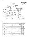
図1の(a) は、第1発明、第4発明、第5発明の一実施例である車両用自動変速機10の骨子図で、(b) は複数の変速段を成立させる際の係合要素および変速比を説明する作動表である。この車両用自動変速機10は、FF車両などの横置き用のもので、ダブルピニオン型の第1遊星歯車装置12を主体として構成されている第1変速部14と、シングルピニオン型の第2遊星歯車装置16およびダブルピニオン型の第3遊星歯車装置18を主体として構成されている第2変速部20とを同軸線上に有し、入力軸22の回転を変速して出力歯車24から出力する。入力軸22は入力部材に相当するもので、エンジン等の走行用駆動源によって回転駆動されるトルクコンバータのタービン軸などであり、出力歯車24は出力部材に相当するもので、差動歯車装置を介して左右の駆動輪を回転駆動する。なお、この車両用自動変速機10は中心線に対して略対称的に構成されており、図1(a) では中心線の下半分が省略されている。以下の実施例についても同様である。
【0021】
上記第1変速部14を構成している第1遊星歯車装置12は、サンギヤS1、キャリアCA1、およびリングギヤR1の3つの回転要素を備えており、サンギヤS1が入力軸22に連結されて回転駆動されるとともに、キャリアCA1が第3ブレーキB3を介して回転不能にケース26に固定されることにより、リングギヤR1が中間出力部材として入力軸22に対して減速回転させられて出力する。また、第2変速部20を構成している第2遊星歯車装置16および第3遊星歯車装置18は、一部が互いに連結されることによって4つの回転要素RM1〜RM4が構成されており、具体的には、第3遊星歯車装置18のサンギヤS3によって第1回転要素RM1が構成され、第2遊星歯車装置16のリングギヤR2および第3遊星歯車装置18のリングギヤR3が互いに連結されて第2回転要素RM2が構成され、第2遊星歯車装置16のキャリアCA2および第3遊星歯車装置18のキャリアCA3が互いに連結されて第3回転要素RM3が構成され、第2遊星歯車装置16のサンギヤS2によって第4回転要素RM4が構成されている。上記第2遊星歯車装置16および第3遊星歯車装置18は、キャリアCA2およびCA3が共通の部材にて構成されているとともに、リングギヤR2およびR3が共通の部材にて構成されており、且つ第2遊星歯車装置16のピニオンギヤが第3遊星歯車装置18の第2ピニオンギヤを兼ねているラビニヨ型の遊星歯車列とされている。
【0022】
上記第1回転要素RM1(サンギヤS3)は第1ブレーキB1によって選択的にケース26に連結されて回転停止させられ、第2回転要素RM2(リングギヤR2、R3)は第2ブレーキB2によって選択的にケース26に連結されて回転停止させられ、第4回転要素RM4(サンギヤS2)は第1クラッチC1を介して選択的に前記入力軸22に連結され、第2回転要素RM2(リングギヤR2、R3)は第2クラッチC2を介して選択的に入力軸22に連結され、第1回転要素RM1(サンギヤS3)は中間出力部材である前記第1遊星歯車装置12のリングギヤR1に一体的に連結され、第3回転要素RM3(キャリアCA2、CA3)は前記出力歯車24に一体的に連結されて回転を出力するようになっている。第1ブレーキB1〜第3ブレーキB3、第1クラッチC1、第2クラッチC2は、何れも油圧シリンダによって摩擦係合させられる多板式の油圧式摩擦係合装置である。なお、第2回転要素RM2とケース26との間には、第2回転要素RM2の正回転(入力軸22と同じ回転方向)を許容しつつ逆回転を阻止する一方向クラッチFが第2ブレーキB2と並列に設けられている。
【0023】
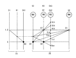
図2は、上記第1変速部14および第2変速部20の各回転要素の回転速度を直線で表すことができる共線図であり、下の横線が回転速度「0」で、上の横線が回転速度「1.0」すなわち入力軸22と同じ回転速度である。また、第1変速部14の各縦線は、左側から順番にサンギヤS1、リングギヤR1、キャリアCA1を表しており、それ等の間隔は第1遊星歯車装置12のギヤ比(=サンギヤの歯数/リングギヤの歯数)ρ1に応じて定められる。第2変速部20の4本の縦線は、左端から右端へ向かって順番に第1回転要素RM1(サンギヤS3)、第2回転要素RM2(リングギヤR2、R3)、第3回転要素RM3(キャリアCA2、CA3)、第4回転要素RM4(サンギヤS2)を表しており、それ等の間隔は第2遊星歯車装置16のギヤ比ρ2および第3遊星歯車装置18のギヤ比ρ3に応じて定められる。
【0024】
そして、上記共線図から明らかなように、第1クラッチC1および第2ブレーキB2が係合させられて、第4回転要素RM4が入力軸22と一体回転させられるとともに第2回転要素RM2が回転停止させられると、出力歯車24に連結された第3回転要素RM3は「1st」で示す回転速度で回転させられ、最も大きい変速比の第1変速段「1st」が成立させられる。第1クラッチC1および第1ブレーキB1が係合させられて、第4回転要素RM4が入力軸22と一体回転させられるとともに第1回転要素RM1が回転停止させられると、第3回転要素RM3は「2nd」で示す回転速度で回転させられ、第1変速段「1st」よりも変速比が小さい第2変速段「2nd」が成立させられる。第1クラッチC1および第3ブレーキB3が係合させられて、第4回転要素RM4が入力軸22と一体回転させられるとともに第1回転要素RM1が第1変速部14を介して減速回転させられると、第3回転要素RM3は「3rd」で示す回転速度で回転させられ、第2変速段「2nd」よりも変速比が小さい第3変速段「3rd」が成立させられる。第1クラッチC1および第2クラッチC2が係合させられて、第2変速部20が入力軸22と一体回転させられると、第3回転要素RM3は「4th」で示す回転速度すなわち入力軸22と同じ回転速度で回転させられ、第3変速段「3rd」よりも変速比が小さい第4変速段「4th」が成立させられる。この第4変速段「4th」の変速比は1である。第2クラッチC2および第3ブレーキB3が係合させられて、第2回転要素RM2が入力軸22と一体回転させられるとともに第1回転要素RM1が第1変速部14を介して減速回転させられると、第3回転要素RM3は「5th」で示す回転速度で回転させられ、第4変速段「4th」よりも変速比が小さい第5変速段「5th」が成立させられる。第2クラッチC2および第1ブレーキB1が係合させられて、第2回転要素RM2が入力軸22と一体回転させられるとともに第1回転要素RM1が回転停止させられると、第3回転要素RM3は「6th」で示す回転速度で回転させられ、第5変速段「5th」よりも変速比が小さい第6変速段「6th」が成立させられる。また、第2ブレーキB2および第3ブレーキB3が係合させられると、第2回転要素RM2が回転停止させられるとともに第1回転要素RM1が第1変速部14を介して減速回転させられることにより、第3回転要素RM3は「Rev」で示す回転速度で逆回転させられ、後進変速段「Rev」が成立させられる。
【0025】
図1の(b) の作動表は、上記各変速段とクラッチC1、C2、ブレーキB1〜B3の作動状態との関係をまとめたもので、「○」は係合、「◎」はエンジンブレーキ時のみ係合を表している。第1変速段「1st」を成立させる第2ブレーキB2には並列に一方向クラッチFが設けられているため、発進時(加速時)には必ずしも第2ブレーキB2を係合させる必要は無いのである。また、各変速段の変速比は、第1遊星歯車装置12、第2遊星歯車装置16、および第3遊星歯車装置18の各ギヤ比ρ1、ρ2、ρ3によって適宜定められ、例えばρ1≒0.45、ρ2≒0.38、ρ3≒0.41とすれば、図1(b) に示す変速比が得られ、ギヤ比ステップ(各変速段間の変速比の比)の値が略適切であるとともにトータルの変速比幅(=3.62/0.59)も6.1程度と大きく、後進変速段「Rev」の変速比も適当で、全体として適切な変速比特性が得られる。
【0026】
このように、本実施例の車両用自動変速機10においては、3組の遊星歯車装置12、16、18と2つのクラッチC1、C2および3つのブレーキB1〜B3を用いて前進6段の多段変速が達成されるため、3つのクラッチおよび2つのブレーキを用いる場合に比較して、クラッチが少なくなった分だけ重量やコスト、軸長が低減される。
【0027】
特に、第2変速部20を構成しているシングルピニオン型の第2遊星歯車装置16およびダブルピニオン型の第3遊星歯車装置18はラビニヨ型の遊星歯車列とされているため、部品点数や軸長が一層低減される。
【0028】
また、3つの遊星歯車装置12、16、18のギヤ比ρ1、ρ2、ρ3を略0.3〜0.6の範囲内として、それ等の遊星歯車装置12、16、18を比較的小型(小径)に維持しつつ、図1(b) に示すように全体として適切な変速比特性を得ることができる。
【0029】
次に、本発明の他の実施例を説明する。なお、以下の実施例において前記実施例と実質的に共通する部分には同一の符号を付して詳しい説明を省略する。
【0030】
図3は、前記図1(a) に相当する骨子図で、この自動変速機30は、前記実施例に比較して第1変速部32が相違し、第2発明〜第5発明の実施例に相当する。第1変速部32は、サンギヤS1、キャリアCA1、およびリングギヤR1の3つの回転要素を有するシングルピニオン型の第1遊星歯車装置34を主体として構成されているが、キャリアCA1には大径部および小径部を有する段付きのピニオンギヤ36が配設されており、サンギヤS1は小径部に噛み合わされるている一方、リングギヤR1は大径部に噛み合わされている。そして、サンギヤS1が入力軸22に連結されて回転駆動されるとともに、リングギヤR1が第3ブレーキB3を介して回転不能にケース26に固定されることにより、キャリアCA1が中間出力部材として入力軸22に対して減速回転させられ、一体的に連結された第1回転要素RM1へ出力するようになっている。
【0031】
このような車両用自動変速機30においても、図1(b) に示す作動表に従って第1変速段「1st」〜第6変速段「6th」の前進6段および後進変速段「Rev」が成立させられ、2つのクラッチC1、C2および3つのブレーキB1〜B3を用いて前進6段の多段変速が達成されるなど、前記実施例と同様の作用効果が得られる。加えて、第1遊星歯車装置34は段付きのピニオンギヤ36を有して構成されているため、そのピニオンギヤ36の回転速度が低減される利点がある。
【0032】
図4および図5は、それぞれ前記図1および図2に対応する図で、この車両用自動変速機40は、前記車両用自動変速機10に比較して、シングルピニオン型の第1遊星歯車装置42を主体として第1変速部44が構成されているとともに、第2変速部20の第2遊星歯車装置16のギヤ比ρ2 は第3遊星歯車装置18のギヤ比ρ3 よりも大きく、且つ一方向クラッチFを省略した点が相違し、第2発明、第4発明、第5発明の実施例に相当する。第1遊星歯車装置42は、サンギヤS1が入力軸22に連結されて回転駆動されるとともに、リングギヤR1が第3ブレーキB3を介して回転不能にケース26に固定されることにより、キャリアCA1が中間出力部材として入力軸22に対して減速回転させられ、一体的に連結された第1回転要素RM1(サンギヤS3)へ出力するようになっている。
【0033】
このような車両用自動変速機40においても、図4(b) に示す作動表に従って第1変速段「1st」〜第6変速段「6th」の前進6段および後進変速段「Rev」が成立させられ、2つのクラッチC1、C2および3つのブレーキB1〜B3を用いて前進6段の多段変速が達成されるなど、前記実施例と同様の作用効果が得られる。但し、この実施例では一方向クラッチFを備えていないため、第1クラッチC1および第2ブレーキB2を共に係合させることによって第1変速段「1st」が成立させられる。
【0034】
また、各変速段の変速比は、第1遊星歯車装置42、第2遊星歯車装置16、および第3遊星歯車装置18の各ギヤ比ρ1、ρ2、ρ3によって適宜定められ、例えばρ1≒0.600、ρ2≒0.456、ρ3≒0.426とすれば、図4(b) に示す変速比が得られ、ギヤ比ステップの値が略適切であるとともにトータルの変速比幅も5.568程度と大きく、後進変速段「Rev」の変速比も適当で、全体として適切な変速比特性が得られる。
【0035】
また、遊星歯車装置42、16、18のギヤ比ρ1、ρ2、ρ3が何れも0.4〜0.6の範囲内であるため、それ等の遊星歯車装置42、16、18として小型(小径)のものを採用でき、一方向クラッチFが省略されたことと相まって、車両用自動変速機40が一層コンパクトに構成される。
【0036】
以上、本発明の実施例を図面に基づいて詳細に説明したが、これ等はあくまでも一実施形態であり、本発明は当業者の知識に基づいて種々の変更,改良を加えた態様で実施することができる。
【図面の簡単な説明】
【図1】 第1発明、第4発明、第5発明の一実施例である車両用自動変速機を説明する図で、(a) は骨子図、(b) は各変速段を成立させるための作動表である。
【図2】図1の実施例の共線図である。
【図3】 第2発明〜第5発明の実施例を示す図で、図1(a) に相当する骨子図である。
【図4】 第2発明、第4発明、第5発明の実施例を示す図で、図1に対応する図である。
【図5】図4の実施例の共線図である。
【符号の説明】
10、30、40:車両用自動変速機(自動変速機) 12、34、42:第1遊星歯車装置 14、32、44:第1変速部 16:第2遊星歯車装置 18:第3遊星歯車装置 20:第2変速部 22:入力軸(入力部材) 24:出力歯車(出力部材) RM1:第1回転要素 RM2:第2回転要素 RM3:第3回転要素 RM4:第4回転要素 C1:第1クラッチ C2:第2クラッチ B1:第1ブレーキ B2:第2ブレーキ B3:第3ブレーキ[0001]
BACKGROUND OF THE INVENTION
The present invention relates to an automatic transmission, and more particularly to an automatic transmission capable of multi-stage shifting with a small number of clutches.
[0002]
[Prior art]
As an automatic transmission for a vehicle, one using a plurality of planetary gear devices, clutches and brakes is often used. The automatic transmission described in
[0003]
[Patent Document 1]
JP 2000-199549 A [Patent Document 2]
JP 2000-266138 A [Patent Document 3]
JP 2001-82555 A [Patent Document 4]
Japanese Patent Application Laid-Open No. 8-105496
[Problems to be solved by the invention]
However, since the clutch rotates, a drum, a seal ring, a centrifugal hydraulic pressure canceling mechanism for the cylinder chamber, etc. are required, which is heavier and more expensive than a brake. It will be disadvantageous.
[0005]
The present invention has been made against the background of the above circumstances, and the object of the present invention is to enable 6-speed forward multi-speed shift with two clutches.
[0006]
[Means for Solving the Problems]
In order to achieve such an object, according to a first invention, in an automatic transmission, (a) any one of the three rotating elements of the first planetary gear device is connected to an input member and driven to rotate; A first transmission portion that is selectively rotated and stopped by a third brake, and the remaining one is decelerated and rotated with respect to the input member as an intermediate output member; and (b) a second planetary gear. The sun gear, the carrier and the ring gear of the device and the third planetary gear device are connected to each other to constitute four rotating elements, and the rotation speed of the four rotating elements can be expressed by a straight line. In the diagram, when the four rotating elements are sequentially designated as a first rotating element, a second rotating element, a third rotating element, and a fourth rotating element from one end to the other end, the first rotating element is The rotation is selectively stopped by one brake, the second rotation element is selectively stopped by the second brake, and the fourth rotation element is selectively connected to the input member via the first clutch. The second rotating element is selectively connected to the input member via a second clutch, the first rotating element is integrally connected to the intermediate output member, and the third rotating element is integrated to the output member. And a second speed changer that is connected and output on the same axis, and (c) the first speed change step having the largest speed change ratio is achieved by engaging the first clutch and the second brake. When the first clutch and the first brake are engaged, a second shift stage having a smaller gear ratio than the first shift stage is established, and the first clutch and the third brake are established. By engaging the brake, a third shift stage having a gear ratio smaller than that of the second shift stage is established, and by engaging the first clutch and the second clutch, the third shift stage. A fourth gear having a smaller gear ratio is established, and the fifth gear having a smaller gear ratio than the fourth gear is established by engaging the second clutch and the third brake. When the second clutch and the first brake are engaged, a sixth shift stage having a gear ratio smaller than that of the fifth shift stage is established, and the second brake and the third brake are engaged. while reverse speed is Ru allowed to establish by being, (d) said first planetary gear set is a double pinion type, either one of the input member of the sun gear and the carrier And the other is selectively stopped by the third brake, and a ring gear is configured as the intermediate output member. (E) the second planetary gear unit is a single pinion type, and the third planetary gear unit (F) The first rotating element is a sun gear of the third planetary gear device, and the second rotating element is a ring gear of the second planetary gear device and the third planetary gear connected to each other. In the ring gear of the device, the third rotating element is a carrier of the second planetary gear device and the carrier of the third planetary gear device which are connected to each other, and the fourth rotating element is a sun gear of the second planetary gear device. It is characterized by that.
The gear ratio is the ratio of the rotational speed of the input member to the rotational speed of the output member (= input member rotational speed / output member rotational speed).
[0008]
According to a second aspect of the present invention, in the automatic transmission, (a) any one of the three rotating elements of the first planetary gear device is connected to the input member and driven to rotate, and the other one is selectively selected by the third brake. The first one of which the remaining one is decelerated and rotated with respect to the input member as an intermediate output member, and (b) the second planetary gear device and the third planetary gear device. Part of the sun gear, the carrier, and the ring gear are connected to each other to constitute four rotating elements, and the four rotations on the collinear chart that can represent the rotational speeds of the four rotating elements in a straight line When the first rotation element, the second rotation element, the third rotation element, and the fourth rotation element are sequentially arranged from one end to the other end, the first rotation element is selectively selected by the first brake. The second rotation element is selectively stopped by the second brake, the fourth rotation element is selectively connected to the input member via the first clutch, and the second rotation element is stopped. Is selectively connected to the input member via a second clutch, the first rotating element is integrally connected to the intermediate output member, and the third rotating element is integrally connected to the output member for output. And (c) a first gear stage having the largest gear ratio is established by engaging the first clutch and the second brake, and By engaging one clutch and the first brake, a second gear having a smaller gear ratio than the first gear is established, and the first clutch and the third brake are engaged. Thus, a third gear stage having a smaller gear ratio than the second gear stage is established, and the first gear and the second clutch are engaged, so that a gear ratio smaller than the third gear stage is established. When the fourth gear is established and the second clutch and the third brake are engaged, a fifth gear having a smaller gear ratio than the fourth gear is established, and the second clutch and the By engaging the first brake, a sixth shift stage having a smaller gear ratio than the fifth shift stage is established, and by engaging the second brake and the third brake, the reverse shift stage is changed. while is established, (d) said first planetary gear set a single-pinion type and the other with one of the sun gear and the ring gear is connected to the input member Is selectively rotated is stopped by the third brake, the carrier is configured as the intermediate output member, (e) said second planetary gear set a single-pinion type, the third planetary gear set is a double pinion type , (f) the first rotating element is a sun gear of the third planetary gear set, with a ring gear of the ring gear and the third planetary gear set of the second rotating element connected to said second planetary gear to each other, wherein The third rotating element is a carrier of the second planetary gear device and the carrier of the third planetary gear device that are connected to each other, and the fourth rotating element is a sun gear of the second planetary gear device .
According to a third aspect of the present invention, in the automatic transmission, (a) any one of the three rotating elements of the first planetary gear device is connected to the input member and driven to rotate, and the other one is selectively selected by the third brake. The first one of which the remaining one is decelerated and rotated with respect to the input member as an intermediate output member, and (b) the second planetary gear device and the third planetary gear device. Part of the sun gear, the carrier, and the ring gear are connected to each other to constitute four rotating elements, and the four rotations on the collinear chart that can represent the rotational speeds of the four rotating elements in a straight line When the first rotation element, the second rotation element, the third rotation element, and the fourth rotation element are sequentially arranged from one end to the other end, the first rotation element is selectively selected by the first brake. The second rotation element is selectively stopped by the second brake, the fourth rotation element is selectively connected to the input member via the first clutch, and the second rotation element is stopped. Is selectively connected to the input member via a second clutch, the first rotating element is integrally connected to the intermediate output member, and the third rotating element is integrally connected to the output member for output. And (c) a first gear stage having the largest gear ratio is established by engaging the first clutch and the second brake, and By engaging one clutch and the first brake, a second gear having a smaller gear ratio than the first gear is established, and the first clutch and the third brake are engaged. Thus, a third gear stage having a smaller gear ratio than the second gear stage is established, and the first gear and the second clutch are engaged, so that a gear ratio smaller than the third gear stage is established. When the fourth gear is established and the second clutch and the third brake are engaged, a fifth gear having a smaller gear ratio than the fourth gear is established, and the second clutch and the By engaging the first brake, a sixth shift stage having a smaller gear ratio than the fifth shift stage is established, and by engaging the second brake and the third brake, the reverse shift stage is changed. while Ru is is established, (d) said first planetary gear set is a single pinion type having a pinion gear with a stage having a large diameter portion and the small-diameter portion, the large diameter of the pinion A sun gear and a ring gear meshed with one and the other of the small diameter portions, and either the sun gear or the ring gear is connected to the input member, and the other is selectively stopped by the third brake. , the carrier is configured as the intermediate output member, (e) said second planetary gear set is a single pinion type, the third planetary gear set is a double pinion type, (f) the first rotating element wherein the A sun gear of a three planetary gear device, wherein the second rotating element is a ring gear of the second planetary gear device connected to each other and a ring gear of the third planetary gear device, and the third rotating element is connected to the second gear of the second planetary gear device. in the carrier of the carrier and the third planetary gear set of the planetary gear device, the fourth rotating element is a sun gear of the second planetary gear set this The features.
According to a fourth aspect of the present invention, in the automatic transmission according to any one of the first to third aspects, the second planetary gear device and the third planetary gear device are configured such that a carrier and a ring gear are respectively formed of a common member, The pinion gear of the second planetary gear unit is a Ravigneaux type planetary gear train that also serves as the second pinion gear of the third planetary gear unit.
According to a fifth aspect of the present invention, in the automatic transmission according to any one of the first to fourth aspects, the output member is an output gear and is disposed between the first transmission unit and the second transmission unit in the axial direction. It is characterized by.
[0009]
【The invention's effect】
In the automatic transmissions according to the first to fifth aspects of the present invention, since the multi-speed shift of 6 forward speeds is achieved using the three planetary gear units, the two clutches, and the three brakes, the three clutches and Compared to the case where two brakes are used, the weight, cost, and shaft length can be reduced by the amount of clutch reduction.
[0010]
In addition, by suitably determined within a range gear ratio of about, for example, 0.3 to 0.6 [rho three planetary gear, while using relatively small (smaller diameter) as a planetary gear device that such The gear ratios of the first gear to the sixth gear can be set appropriately. Further, since the carriers and the ring gears of the single pinion type second planetary gear device and the double pinion type third planetary gear device are connected to each other, as in the fourth invention, they are shared to form a Ravigneaux type. By doing so, the number of parts and the shaft length can be further reduced.
[0011]
DETAILED DESCRIPTION OF THE INVENTION
The present invention is suitably applied to an automatic transmission for a vehicle. For example, rotation is input from a traveling drive source such as an internal combustion engine through a fluid coupling such as a torque converter, and a gear is output at a predetermined speed ratio. It is transmitted from the output member such as the shaft to the left and right drive wheels via the differential gear device, but can also be applied to automatic transmissions other than those for vehicles. The input member is, for example, a turbine shaft of a torque converter.
[0012]
The mounting position of the automatic transmission with respect to the vehicle is such that the axis of the automatic transmission is in the longitudinal direction of the vehicle even in a horizontal type such as an FF (front engine / front drive) vehicle in which the axis of the automatic transmission is in the width direction of the vehicle. A vertical installation type such as an FR (front engine / rear drive) vehicle may be used.
[0013]
Automatic transmission may be one to switch the automatic gear position according to the operating conditions such as accelerator operation amount and the vehicle speed, but also have good ones for switching the gear position according to the driver's switch operation (such as up-down operation).
[0016]
As the first brake to the third brake, the first clutch, and the second clutch, hydraulic friction engagement devices such as a multi-plate type, a single plate type, and a belt type that are frictionally engaged by a hydraulic cylinder are preferably used. Other types of engagement devices, such as a formula, can also be employed. In order to facilitate shift control, a one-way clutch may be provided in parallel with the brakes and clutches. For example, if a one-way clutch is provided in parallel with the second brake, the first shift stage can be established only by engaging the first clutch, and the second shift stage can be switched simply by engaging the first brake. Can do. If the engine brake is not required, a one-way clutch may be provided instead of the second brake. The one-way clutch has the same function as the brake in that it stops rotating. In addition, various modes such as providing a brake and a one-way clutch connected in series in parallel with the first brake are possible.
[0017]
The positional relationship between the first transmission unit and the second transmission unit, and the positional relationship between the second planetary gear unit and the third planetary gear unit of the second transmission unit are not particularly limited, and for example, the first planetary gear unit and the second planetary gear unit are not limited. Various modes are possible, such as arranging the third planetary gear device between the planetary gear devices. For the clutch and brake, for example, various modes such as concentrating at one end are possible.
[0018]
In carrying out the first to third inventions , it is desirable to use a Ravigneaux type planetary gear train as in the fourth invention. However, the carrier and the ring gear are configured separately and connected together by a connecting member or the like. Each pinion gear may be provided separately.
[0020]
【Example】
Hereinafter, embodiments of the present invention will be described in detail with reference to the drawings.
FIG. 1 (a) is a skeleton diagram of an automatic transmission 10 for a vehicle that is an embodiment of the first , fourth, and fifth inventions, and FIG. 1 (b) is a relationship for establishing a plurality of shift stages. It is an operation | movement table explaining a combined element and a gear ratio. The automatic transmission 10 for a vehicle is for horizontal installation of an FF vehicle or the like, and includes a
[0021]
The first
[0022]
The first rotating element RM1 (sun gear S3) is selectively connected to the
[0023]
FIG. 2 is a collinear diagram in which the rotational speeds of the rotating elements of the
[0024]
As is apparent from the collinear diagram, the first clutch C1 and the second brake B2 are engaged, the fourth rotating element RM4 is rotated integrally with the
[0025]
The operation table of FIG. 1 (b) summarizes the relationship between the above-mentioned shift speeds and the operation states of the clutches C1, C2 and the brakes B1 to B3, where “◯” indicates engagement and “◎” indicates engine brake. Only the time represents engagement. Since the one-way clutch F is provided in parallel with the second brake B2 that establishes the first shift stage “1st”, it is not always necessary to engage the second brake B2 when starting (acceleration). is there. Further, the gear ratio of each gear stage is appropriately determined by the gear ratios ρ1, ρ2, and ρ3 of the first
[0026]
As described above, in the vehicle automatic transmission 10 according to the present embodiment, the multi-stage of six forward stages using the three
[0027]
In particular, since the single pinion type second
[0028]
Further, the gear ratios ρ1, ρ2, and ρ3 of the three
[0029]
Next, another embodiment of the present invention will be described. In the following embodiments, parts that are substantially the same as those in the above embodiments are denoted by the same reference numerals, and detailed description thereof is omitted.
[0030]
FIG. 3 is a skeleton diagram corresponding to FIG. 1 (a). The
[0031]
Also in such an
[0032]
FIGS. 4 and 5 are diagrams corresponding to FIGS. 1 and 2, respectively. This vehicle
[0033]
Also in the vehicular
[0034]
Further, the gear ratio of each gear stage is appropriately determined by the gear ratios ρ1, ρ2, and ρ3 of the first
[0035]
Further, since the gear ratios ρ1, ρ2, and ρ3 of the
[0036]
As mentioned above, although the Example of this invention was described in detail based on drawing, these are one embodiment to the last, and this invention is implemented in the aspect which added the various change and improvement based on the knowledge of those skilled in the art. be able to.
[Brief description of the drawings]
FIGS. 1A and 1B are diagrams for explaining an automatic transmission for a vehicle according to an embodiment of the first invention, the fourth invention, and the fifth invention . FIG. 1A is a skeleton diagram, and FIG. It is an operation table.
FIG. 2 is a collinear diagram of the embodiment of FIG.
FIG. 3 is a view showing an embodiment of the second invention to the fifth invention, and is a skeleton diagram corresponding to FIG.
FIG. 4 is a diagram showing an embodiment of the second invention, the fourth invention, and the fifth invention and corresponding to FIG. 1;
FIG. 5 is a collinear diagram for the embodiment of FIG. 4;
[Explanation of symbols]
DESCRIPTION OF
Claims (5)
第2遊星歯車装置および第3遊星歯車装置のサンギヤ、キャリア、およびリングギヤの一部が互いに連結されることによって4つの回転要素が構成されるとともに、該4つの回転要素の回転速度を直線で表すことができる共線図上において該4つの回転要素を一端から他端へ向かって順番に第1回転要素、第2回転要素、第3回転要素、および第4回転要素とした時、該第1回転要素は第1ブレーキによって選択的に回転停止させられ、該第2回転要素は第2ブレーキによって選択的に回転停止させられ、該第4回転要素は第1クラッチを介して選択的に前記入力部材に連結され、該第2回転要素は第2クラッチを介して選択的に前記入力部材に連結され、該第1回転要素は前記中間出力部材に一体的に連結され、該第3回転要素は出力部材に一体的に連結されて出力する第2変速部と、
を同軸線上に備えており、
前記第1クラッチおよび前記第2ブレーキが係合させられることによって最も大きい変速比の第1変速段が成立させられ、前記第1クラッチおよび前記第1ブレーキが係合させられることによって前記第1変速段よりも変速比が小さい第2変速段が成立させられ、前記第1クラッチおよび前記第3ブレーキが係合させられることによって前記第2変速段よりも変速比が小さい第3変速段が成立させられ、前記第1クラッチおよび前記第2クラッチが係合させられることによって前記第3変速段よりも変速比が小さい第4変速段が成立させられ、前記第2クラッチおよび前記第3ブレーキが係合させられることによって前記第4変速段よりも変速比が小さい第5変速段が成立させられ、前記第2クラッチおよび前記第1ブレーキが係合させられることによって前記第5変速段よりも変速比が小さい第6変速段が成立させられ、前記第2ブレーキおよび前記第3ブレーキが係合させられることによって後進変速段が成立させられる一方、
前記第1遊星歯車装置はダブルピニオン型で、そのサンギヤおよびキャリアの何れか一方が前記入力部材に連結されるとともに他方が前記第3ブレーキによって選択的に回転停止させられ、リングギヤが前記中間出力部材として構成され、
前記第2遊星歯車装置はシングルピニオン型で、前記第3遊星歯車装置はダブルピニオン型であり、
前記第1回転要素は前記第3遊星歯車装置のサンギヤで、前記第2回転要素は互いに連結された前記第2遊星歯車装置のリングギヤおよび前記第3遊星歯車装置のリングギヤで、前記第3回転要素は互いに連結された前記第2遊星歯車装置のキャリアおよび前記第3遊星歯車装置のキャリアで、前記第4回転要素は前記第2遊星歯車装置のサンギヤである
ことを特徴とする自動変速機。Any one of the three rotating elements of the first planetary gear device is connected to the input member and driven to rotate, and the other one is selectively stopped by the third brake, so that the remaining one is intermediate. A first speed changer that is rotated and decelerated with respect to the input member as an output member;
The sun gear, the carrier, and part of the ring gear of the second planetary gear device and the third planetary gear device are connected to each other to constitute four rotating elements, and the rotational speed of the four rotating elements is represented by a straight line. In the collinear diagram, when the four rotating elements are sequentially designated as a first rotating element, a second rotating element, a third rotating element, and a fourth rotating element from one end to the other end, the first rotating element The rotating element is selectively stopped by the first brake, the second rotating element is selectively stopped by the second brake, and the fourth rotating element is selectively input via the first clutch. Connected to a member, the second rotating element is selectively connected to the input member via a second clutch, the first rotating element is integrally connected to the intermediate output member, and the third rotating element is Output member A second transmission unit which outputs are integrally connected,
On the coaxial line,
The first shift stage having the largest gear ratio is established by engaging the first clutch and the second brake, and the first shift is performed by engaging the first clutch and the first brake. A second gear stage having a gear ratio smaller than that of the gear stage is established, and the third gear stage having a gear ratio smaller than that of the second gear stage is established by engaging the first clutch and the third brake. When the first clutch and the second clutch are engaged, a fourth shift stage having a gear ratio smaller than that of the third shift stage is established, and the second clutch and the third brake are engaged. As a result, a fifth shift stage having a gear ratio smaller than that of the fourth shift stage is established, and the second clutch and the first brake are engaged. While the fifth sixth gear position gear ratio than gear speed is small is caused to establish the reverse shift stage Ru is thereby establishing the second brake and the third brake is engaged by,
The first planetary gear device is a double pinion type, and either one of the sun gear and the carrier is connected to the input member, the other is selectively stopped by the third brake, and a ring gear is connected to the intermediate output member. Configured as
The second planetary gear device is a single pinion type, and the third planetary gear device is a double pinion type,
The first rotating element is a sun gear of the third planetary gear unit, the second rotating element is a ring gear of the second planetary gear unit and a ring gear of the third planetary gear unit that are connected to each other, and the third rotating element Is a carrier of the second planetary gear device and a carrier of the third planetary gear device that are connected to each other, and the fourth rotating element is a sun gear of the second planetary gear device.
第2遊星歯車装置および第3遊星歯車装置のサンギヤ、キャリア、およびリングギヤの一部が互いに連結されることによって4つの回転要素が構成されるとともに、該4つの回転要素の回転速度を直線で表すことができる共線図上において該4つの回転要素を一端から他端へ向かって順番に第1回転要素、第2回転要素、第3回転要素、および第4回転要素とした時、該第1回転要素は第1ブレーキによって選択的に回転停止させられ、該第2回転要素は第2ブレーキによって選択的に回転停止させられ、該第4回転要素は第1クラッチを介して選択的に前記入力部材に連結され、該第2回転要素は第2クラッチを介して選択的に前記入力部材に連結され、該第1回転要素は前記中間出力部材に一体的に連結され、該第3回転要素は出力部材に一体的に連結されて出力する第2変速部と、The sun gear, the carrier, and part of the ring gear of the second planetary gear device and the third planetary gear device are connected to each other to constitute four rotating elements, and the rotational speed of the four rotating elements is represented by a straight line. In the collinear diagram, when the four rotating elements are sequentially designated as a first rotating element, a second rotating element, a third rotating element, and a fourth rotating element from one end to the other end, the first rotating element The rotating element is selectively stopped by the first brake, the second rotating element is selectively stopped by the second brake, and the fourth rotating element is selectively input via the first clutch. Connected to a member, the second rotating element is selectively connected to the input member via a second clutch, the first rotating element is integrally connected to the intermediate output member, and the third rotating element is Output member A second transmission unit which outputs are integrally connected,
を同軸線上に備えており、On the coaxial line,
前記第1クラッチおよび前記第2ブレーキが係合させられることによって最も大きい変速比の第1変速段が成立させられ、前記第1クラッチおよび前記第1ブレーキが係合させられることによって前記第1変速段よりも変速比が小さい第2変速段が成立させられ、前記第1クラッチおよび前記第3ブレーキが係合させられることによって前記第2変速段よりも変速比が小さい第3変速段が成立させられ、前記第1クラッチおよび前記第2クラッチが係合させられることによって前記第3変速段よりも変速比が小さい第4変速段が成立させられ、前記第2クラッチおよび前記第3ブレーキが係合させられることによって前記第4変速段よりも変速比が小さい第5変速段が成立させられ、前記第2クラッチおよび前記第1ブレーキが係合させられることによって前記第5変速段よりも変速比が小さい第6変速段が成立させられ、前記第2ブレーキおよび前記第3ブレーキが係合させられることによって後進変速段が成立させられる一方、The first shift stage having the largest gear ratio is established by engaging the first clutch and the second brake, and the first shift is performed by engaging the first clutch and the first brake. A second gear stage having a gear ratio smaller than that of the gear stage is established, and the third gear stage having a gear ratio smaller than that of the second gear stage is established by engaging the first clutch and the third brake. When the first clutch and the second clutch are engaged, a fourth shift stage having a gear ratio smaller than that of the third shift stage is established, and the second clutch and the third brake are engaged. As a result, a fifth shift stage having a gear ratio smaller than that of the fourth shift stage is established, and the second clutch and the first brake are engaged. While the sixth speed gear ratio than the fifth gear position is small is caused to establish the reverse shift stage by the second brake and the third brake are engaged, is established by,
前記第1遊星歯車装置はシングルピニオン型で、そのサンギヤおよびリングギヤの何れか一方が前記入力部材に連結されるとともに他方が前記第3ブレーキによって選択的に回転停止させられ、キャリアが前記中間出力部材として構成され、The first planetary gear unit is a single pinion type, and either one of the sun gear and the ring gear is connected to the input member, the other is selectively stopped by the third brake, and the carrier is the intermediate output member. Configured as
前記第2遊星歯車装置はシングルピニオン型で、前記第3遊星歯車装置はダブルピニオン型であり、The second planetary gear unit is a single pinion type, and the third planetary gear unit is a double pinion type;
前記第1回転要素は前記第3遊星歯車装置のサンギヤで、前記第2回転要素は互いに連結された前記第2遊星歯車装置のリングギヤおよび前記第3遊星歯車装置のリングギヤで、前記第3回転要素は互いに連結された前記第2遊星歯車装置のキャリアおよび前記第3遊星歯車装置のキャリアで、前記第4回転要素は前記第2遊星歯車装置のサンギヤであるThe first rotating element is a sun gear of the third planetary gear device, the second rotating element is a ring gear of the second planetary gear device and a ring gear of the third planetary gear device that are connected to each other, and the third rotating element Is a carrier of the second planetary gear device and a carrier of the third planetary gear device that are connected to each other, and the fourth rotating element is a sun gear of the second planetary gear device.
ことを特徴とする自動変速機。An automatic transmission characterized by that.
第2遊星歯車装置および第3遊星歯車装置のサンギヤ、キャリア、およびリングギヤの一部が互いに連結されることによって4つの回転要素が構成されるとともに、該4つの回転要素の回転速度を直線で表すことができる共線図上において該4つの回転要素を一端から他端へ向かって順番に第1回転要素、第2回転要素、第3回転要素、および第4回転要素とした時、該第1回転要素は第1ブレーキによって選択的に回転停止させられ、該第2回転要素は第2ブレーキによって選択的に回転停止させられ、該第4回転要素は第1クラッチを介して選択的に前記入力部材に連結され、該第2回転要素は第2クラッチを介して選択的に前記入力部材に連結され、該第1回転要素は前記中間出力部材に一体的に連結され、該第3回転要素は出力部材に一体的に連結されて出力する第2変速部と、The sun gear, the carrier, and part of the ring gear of the second planetary gear device and the third planetary gear device are connected to each other to constitute four rotating elements, and the rotational speed of the four rotating elements is represented by a straight line. In the collinear diagram, when the four rotating elements are sequentially designated as a first rotating element, a second rotating element, a third rotating element, and a fourth rotating element from one end to the other end, the first rotating element The rotating element is selectively stopped by the first brake, the second rotating element is selectively stopped by the second brake, and the fourth rotating element is selectively input via the first clutch. Connected to a member, the second rotating element is selectively connected to the input member via a second clutch, the first rotating element is integrally connected to the intermediate output member, and the third rotating element is Output member A second transmission unit which outputs are integrally connected,
を同軸線上に備えており、On the coaxial line,
前記第1クラッチおよび前記第2ブレーキが係合させられることによって最も大きい変速比の第1変速段が成立させられ、前記第1クラッチおよび前記第1ブレーキが係合させられることによって前記第1変速段よりも変速比が小さい第2変速段が成立させられ、前記第1クラッチおよび前記第3ブレーキが係合させられることによって前記第2変速段よりも変速比が小さい第3変速段が成立させられ、前記第1クラッチおよび前記第2クラッチが係合させられることによって前記第3変速段よりも変速比が小さい第4変速段が成立させられ、前記第2クラッチおよび前記第3ブレーキが係合させられることによって前記第4変速段よりも変速比が小さい第5変速段が成立させられ、前記第2クラッチおよび前記第1ブレーキが係合させられることによって前記第5変速段よりも変速比が小さい第6変速段が成立させられ、前記第2ブレーキおよび前記第3ブレーキが係合させられることによって後進変速段が成立させられる一方、The first shift stage having the largest gear ratio is established by engaging the first clutch and the second brake, and the first shift is performed by engaging the first clutch and the first brake. A second gear stage having a gear ratio smaller than that of the gear stage is established, and the third gear stage having a gear ratio smaller than that of the second gear stage is established by engaging the first clutch and the third brake. When the first clutch and the second clutch are engaged, a fourth shift stage having a gear ratio smaller than the third shift stage is established, and the second clutch and the third brake are engaged. As a result, a fifth shift stage having a gear ratio smaller than that of the fourth shift stage is established, and the second clutch and the first brake are engaged. While the sixth speed gear ratio than the fifth gear position is small is caused to establish the reverse shift stage by the second brake and the third brake are engaged, is established by,
前記第1遊星歯車装置は、大径部および小径部を有する段付きのピニオンギヤを有するシングルピニオン型で、該ピニオンギヤの大径部、小径部の一方および他方に噛み合わされるサンギヤおよびリングギヤを備えており、該サンギヤおよび該リングギヤの何れか一方が前記入力部材に連結されるとともに他方が前記第3ブレーキによって選択的に回転停The first planetary gear device is a single pinion type having a stepped pinion gear having a large diameter portion and a small diameter portion, and includes a sun gear and a ring gear meshed with one of the large diameter portion and the small diameter portion of the pinion gear. One of the sun gear and the ring gear is connected to the input member, and the other is selectively stopped by the third brake. 止させられ、キャリアが前記中間出力部材として構成され、The carrier is configured as the intermediate output member,
前記第2遊星歯車装置はシングルピニオン型で、前記第3遊星歯車装置はダブルピニオン型であり、The second planetary gear unit is a single pinion type, and the third planetary gear unit is a double pinion type;
前記第1回転要素は前記第3遊星歯車装置のサンギヤで、前記第2回転要素は互いに連結された前記第2遊星歯車装置のリングギヤおよび前記第3遊星歯車装置のリングギヤで、前記第3回転要素は互いに連結された前記第2遊星歯車装置のキャリアおよび前記第3遊星歯車装置のキャリアで、前記第4回転要素は前記第2遊星歯車装置のサンギヤであるThe first rotating element is a sun gear of the third planetary gear device, the second rotating element is a ring gear of the second planetary gear device and a ring gear of the third planetary gear device that are connected to each other, and the third rotating element Is a carrier of the second planetary gear device and a carrier of the third planetary gear device that are connected to each other, and the fourth rotating element is a sun gear of the second planetary gear device.
ことを特徴とする自動変速機。An automatic transmission characterized by that.
ことを特徴とする請求項1〜3の何れか1項に記載の自動変速機。In the second planetary gear device and the third planetary gear device, the carrier and the ring gear are respectively constituted by a common member, and the pinion gear of the second planetary gear device also serves as the second pinion gear of the third planetary gear device. The automatic transmission according to any one of claims 1 to 3, wherein the automatic transmission is a Ravigneaux type planetary gear train.
ことを特徴とする請求項1〜4の何れか1項に記載の自動変速機。The automatic transmission according to any one of claims 1 to 4, wherein the automatic transmission is provided.
Priority Applications (5)
| Application Number | Priority Date | Filing Date | Title |
|---|---|---|---|
| JP2002321851A JP3763296B2 (en) | 2001-12-10 | 2002-11-05 | Automatic transmission |
| DE10257470A DE10257470B4 (en) | 2001-12-10 | 2002-12-09 | Automatically shiftable transmission |
| KR10-2002-0077833A KR100504520B1 (en) | 2001-12-10 | 2002-12-09 | Automatic transmission |
| CNB021564086A CN1209562C (en) | 2001-12-10 | 2002-12-10 | Automatic speed variator |
| US10/314,967 US6849022B2 (en) | 2001-12-10 | 2002-12-10 | Automatic transmission |
Applications Claiming Priority (3)
| Application Number | Priority Date | Filing Date | Title |
|---|---|---|---|
| JP2001375771 | 2001-12-10 | ||
| JP2001-375771 | 2001-12-10 | ||
| JP2002321851A JP3763296B2 (en) | 2001-12-10 | 2002-11-05 | Automatic transmission |
Publications (3)
| Publication Number | Publication Date |
|---|---|
| JP2003240068A JP2003240068A (en) | 2003-08-27 |
| JP2003240068A5 JP2003240068A5 (en) | 2005-04-07 |
| JP3763296B2 true JP3763296B2 (en) | 2006-04-05 |
Family
ID=26624966
Family Applications (1)
| Application Number | Title | Priority Date | Filing Date |
|---|---|---|---|
| JP2002321851A Expired - Fee Related JP3763296B2 (en) | 2001-12-10 | 2002-11-05 | Automatic transmission |
Country Status (5)
| Country | Link |
|---|---|
| US (1) | US6849022B2 (en) |
| JP (1) | JP3763296B2 (en) |
| KR (1) | KR100504520B1 (en) |
| CN (1) | CN1209562C (en) |
| DE (1) | DE10257470B4 (en) |
Families Citing this family (47)
| Publication number | Priority date | Publication date | Assignee | Title |
|---|---|---|---|---|
| EP1491794B1 (en) * | 2002-03-29 | 2012-08-22 | Aisin Aw Co., Ltd. | Automatic transmission |
| US20030232689A1 (en) * | 2002-06-13 | 2003-12-18 | Raymond James Haka | Dual input clutch transmission having synchronizers for establishing speed ratios |
| JP4110281B2 (en) * | 2002-12-27 | 2008-07-02 | アイシン・エィ・ダブリュ株式会社 | Automatic transmission |
| CN100458220C (en) * | 2003-09-10 | 2009-02-04 | 爱信艾达株式会社 | Automatic transmission for vehicle |
| US7195578B2 (en) * | 2004-12-03 | 2007-03-27 | Axiom Automotive Technologies, Inc. | Automatic transmission and gear train |
| KR100610793B1 (en) * | 2004-08-11 | 2006-08-09 | 현대자동차주식회사 | A 6-speed power train of an automatic transmission |
| KR100610792B1 (en) * | 2004-08-11 | 2006-08-09 | 현대자동차주식회사 | A 6-speed power train of an automatic transmission |
| KR100623777B1 (en) | 2004-11-19 | 2006-09-19 | 현대자동차주식회사 | A 6th-SPEED POWER TRAIN OF AN AUTOMATIC TRANSMISSION FOR A VEHICLE |
| KR100999453B1 (en) | 2004-11-24 | 2010-12-09 | 현대자동차주식회사 | Automatic transmission for advance 6-speed and back 4-speed of front wheel drive |
| US20060122027A1 (en) * | 2004-12-03 | 2006-06-08 | Dalenberg Scott R | Automatic transmission and gear train |
| US7238131B2 (en) * | 2005-01-04 | 2007-07-03 | General Motors Corporation | Electrically variable transmission having three planetary gear sets and three fixed interconnections |
| WO2007000521A2 (en) * | 2005-05-10 | 2007-01-04 | Renault S.A.S | Transmission system comprising planetary gears |
| FR2885665B1 (en) * | 2005-05-10 | 2007-06-29 | Renault Sas | EPICYCLOID TRAIN GEARBOX SYSTEM |
| JP4867240B2 (en) * | 2005-09-07 | 2012-02-01 | トヨタ自動車株式会社 | Control device for automatic transmission |
| CN101375084B (en) * | 2006-03-29 | 2012-03-28 | 爱信艾达株式会社 | Automatic transmission |
| KR100802932B1 (en) * | 2006-05-09 | 2008-02-14 | 현대자동차주식회사 | A six-speed power train of an automatic transmission for a vehicle |
| KR100836910B1 (en) * | 2006-05-11 | 2008-06-11 | 현대자동차주식회사 | A six-speed power train of an automatic transmission for a vehicle |
| KR100802935B1 (en) * | 2006-05-15 | 2008-02-13 | 현대자동차주식회사 | A six-speed power train of an automatic transmission for a vehicle |
| US7699745B2 (en) * | 2006-05-25 | 2010-04-20 | Gm Global Technology Operations, Inc. | Multi-speed transmissions with a long pinion and one fixed interconnection |
| KR100802933B1 (en) * | 2006-05-29 | 2008-02-14 | 현대자동차주식회사 | A six-speed power train of an automatic transmission for a vehicle |
| KR100836912B1 (en) * | 2006-05-29 | 2008-06-11 | 현대자동차주식회사 | A six-speed power train of an automatic transmission for a vehicle |
| KR100802936B1 (en) * | 2006-05-29 | 2008-02-14 | 현대자동차주식회사 | A six-speed power train of an automatic transmission for a vehicle |
| KR100802938B1 (en) * | 2006-05-29 | 2008-02-14 | 현대자동차주식회사 | A six-speed power train of an automatic transmission for a vehicle |
| KR100811759B1 (en) * | 2006-05-30 | 2008-03-07 | 현대자동차주식회사 | A six?speed power train of an automatic transmission for a vehicle |
| KR100793878B1 (en) * | 2006-07-11 | 2008-01-15 | 현대자동차주식회사 | A six-speed power train of an automatic transmission for a vehicle |
| KR100793882B1 (en) | 2006-07-20 | 2008-01-15 | 현대자동차주식회사 | Power train for automatic transmission |
| JP4961882B2 (en) | 2006-07-31 | 2012-06-27 | アイシン・エィ・ダブリュ株式会社 | Shift control device for automatic transmission |
| JP4428368B2 (en) * | 2006-08-03 | 2010-03-10 | トヨタ自動車株式会社 | Manufacturing method of rotating linear motion conversion mechanism |
| KR101230822B1 (en) * | 2006-08-07 | 2013-02-07 | 현대자동차주식회사 | A 8 speed power train of an automatic transmission |
| CN101165371B (en) * | 2006-10-18 | 2010-05-12 | 许志刚 | Multi-segment type power automatic speed controller |
| KR100803303B1 (en) * | 2006-10-27 | 2008-02-13 | 현대자동차주식회사 | A 8th-speed power train of an automatic transmission |
| FR2916030B1 (en) * | 2007-05-10 | 2009-10-09 | Gm Global Tech Operations Inc | AUTOMATIC TRANSMISSION |
| KR100887966B1 (en) | 2007-08-16 | 2009-03-12 | 현대자동차주식회사 | Gear train in an automatic transmission for vehicles |
| KR100916775B1 (en) * | 2007-08-16 | 2009-09-14 | 현대자동차주식회사 | 6 - speed power train of an automatic transmission for a vehicle |
| JP4577340B2 (en) * | 2007-09-07 | 2010-11-10 | トヨタ自動車株式会社 | Control device for automatic transmission |
| US8070642B2 (en) * | 2007-11-01 | 2011-12-06 | GM Global Technology Operations LLC | Gear and clutch arrangement for multi-speed transmission |
| US8062163B2 (en) * | 2007-11-01 | 2011-11-22 | GM Global Technology Operations LLC | Gear and clutch arrangement for multi-speed transmission |
| CN101251174B (en) * | 2008-01-29 | 2010-11-17 | 郭克亚 | Planetary multilevel gear drive mechanism |
| CN101637901B (en) * | 2008-07-31 | 2011-12-07 | 苏州宝时得电动工具有限公司 | Speed changer |
| US8353803B2 (en) | 2008-08-07 | 2013-01-15 | Honda Motor Co., Ltd. | Automatic transmission |
| JP4798225B2 (en) * | 2009-01-08 | 2011-10-19 | トヨタ自動車株式会社 | Automatic transmission |
| JP4781442B2 (en) * | 2009-03-04 | 2011-09-28 | 本田技研工業株式会社 | transmission |
| CN102022489A (en) * | 2009-09-15 | 2011-04-20 | 浙江吉利控股集团有限公司 | Double-planetary gear four-axis transmission device |
| DE102010010663A1 (en) * | 2010-03-01 | 2011-09-01 | A + M Fertigungstechnik Gmbh | transmission |
| CN102042372B (en) * | 2011-01-07 | 2012-10-24 | 广州科立源机电科技有限公司 | Multi-speed transmission |
| JP5876969B2 (en) | 2013-03-26 | 2016-03-02 | ジヤトコ株式会社 | Automatic transmission for vehicles |
| DE102016216314A1 (en) * | 2016-08-30 | 2018-03-01 | Volkswagen Aktiengesellschaft | Transmission assembly and multi-stage hybrid powertrain for a motor vehicle |
Family Cites Families (28)
| Publication number | Priority date | Publication date | Assignee | Title |
|---|---|---|---|---|
| US4872376A (en) * | 1987-06-04 | 1989-10-10 | Toyota Jidosha Kabushiki Kaisha | Transmission for a vehicle having improved performance for shifting between speed stages |
| JPH0356747A (en) * | 1989-07-21 | 1991-03-12 | Nissan Motor Co Ltd | Planetary gear transmission |
| FR2656055B1 (en) | 1989-12-18 | 1994-04-29 | Lepelletier Pierre | MULTI-SPEED AUTOMATIC TRANSMISSION FOR MOTOR VEHICLE. |
| JP2956173B2 (en) | 1990-09-05 | 1999-10-04 | 日産自動車株式会社 | Planetary gear train of automatic transmission |
| JP2778278B2 (en) * | 1991-03-14 | 1998-07-23 | 日産自動車株式会社 | Planetary gear transmission |
| JP3102046B2 (en) * | 1991-03-20 | 2000-10-23 | 日産自動車株式会社 | Planetary gear train of automatic transmission |
| JPH0526310A (en) | 1991-07-18 | 1993-02-02 | Nissan Motor Co Ltd | Epicyclic gear transmission mechanism |
| DE4222911A1 (en) * | 1992-03-06 | 1993-09-09 | Renk Ag | Multi-gear gearbox with planetary gearing and switch coupling - has first and second separately operated switching brakes to block or release rotation of the first planetary support of first planetary gear. |
| JP3246139B2 (en) * | 1993-11-08 | 2002-01-15 | トヨタ自動車株式会社 | Gearbox for automatic transmission |
| US5435792A (en) * | 1994-03-28 | 1995-07-25 | Ford Motor Company | Multiple-speed automatic transmission for motor vehicles |
| KR0145492B1 (en) * | 1994-10-03 | 1998-08-01 | 와다 아키히로 | Gear speed change device |
| JP3446345B2 (en) | 1994-10-03 | 2003-09-16 | トヨタ自動車株式会社 | Gear transmission |
| US5599251A (en) * | 1995-09-27 | 1997-02-04 | Ford Motor Company | Six speed automatic transmission for automotive vehicles |
| JP3710180B2 (en) | 1995-10-31 | 2005-10-26 | ジヤトコ株式会社 | Gear transmission for automatic transmission |
| US5788596A (en) * | 1996-11-08 | 1998-08-04 | General Motors Corporation | Transmission and control with output shaft braking |
| JP3906576B2 (en) * | 1998-07-28 | 2007-04-18 | アイシン・エィ・ダブリュ株式会社 | Automatic transmission for vehicles |
| JP4096468B2 (en) | 1998-10-30 | 2008-06-04 | アイシン・エィ・ダブリュ株式会社 | Automatic transmission for vehicles |
| JP4710098B2 (en) * | 1999-02-16 | 2011-06-29 | アイシン・エィ・ダブリュ株式会社 | Automatic transmission |
| DE19910299C1 (en) | 1999-03-10 | 2001-04-19 | Daimler Chrysler Ag | Planetary gear change transmission with three partial transmissions |
| US6503170B1 (en) | 1999-08-20 | 2003-01-07 | Toyota Jidosha Kabushiki Kaisha | Control device for an automatic transmission |
| JP4244461B2 (en) | 1999-09-09 | 2009-03-25 | アイシン・エィ・ダブリュ株式会社 | Automatic transmission for vehicles |
| JP3777929B2 (en) | 1999-12-24 | 2006-05-24 | アイシン精機株式会社 | Transmission |
| JP3463274B2 (en) | 2000-01-11 | 2003-11-05 | アイシン・エィ・ダブリュ株式会社 | Automatic transmission for vehicles |
| US6422969B1 (en) * | 2000-08-14 | 2002-07-23 | General Motors Corporation | Powertrain with a six speed planetary transmission having three planetary gear sets |
| US6422968B1 (en) * | 2001-01-22 | 2002-07-23 | General Motors Corporation | Compact six speed power transmission |
| US6705967B2 (en) * | 2001-02-21 | 2004-03-16 | General Motors Corporation | Six-speed transmission with three planetary gear sets and five torque transmitting mechanisms |
| US20020183160A1 (en) * | 2001-06-05 | 2002-12-05 | Chi-Kuan Kao | Six-speed planetary transmission mechanisms with two clutches and three brakes |
| US6648789B1 (en) * | 2002-06-18 | 2003-11-18 | General Motors Corporation | Multi-speed transmissions with three interconnected planetary gear sets |
-
2002
- 2002-11-05 JP JP2002321851A patent/JP3763296B2/en not_active Expired - Fee Related
- 2002-12-09 DE DE10257470A patent/DE10257470B4/en not_active Expired - Fee Related
- 2002-12-09 KR KR10-2002-0077833A patent/KR100504520B1/en active IP Right Grant
- 2002-12-10 US US10/314,967 patent/US6849022B2/en not_active Expired - Lifetime
- 2002-12-10 CN CNB021564086A patent/CN1209562C/en not_active Expired - Fee Related
Also Published As
| Publication number | Publication date |
|---|---|
| KR100504520B1 (en) | 2005-08-01 |
| CN1425860A (en) | 2003-06-25 |
| US20030109353A1 (en) | 2003-06-12 |
| DE10257470B4 (en) | 2010-06-17 |
| CN1209562C (en) | 2005-07-06 |
| KR20030047828A (en) | 2003-06-18 |
| DE10257470A1 (en) | 2003-06-26 |
| US6849022B2 (en) | 2005-02-01 |
| JP2003240068A (en) | 2003-08-27 |
Similar Documents
| Publication | Publication Date | Title |
|---|---|---|
| JP3763296B2 (en) | Automatic transmission | |
| JP3736481B2 (en) | Automatic transmission | |
| JP4380291B2 (en) | Planetary gear type multi-stage transmission for vehicles | |
| JP4148061B2 (en) | Multi-speed transmission | |
| JP4127162B2 (en) | Multi-speed transmission | |
| JP3777929B2 (en) | Transmission | |
| JP4345146B2 (en) | Transmission | |
| JP2003130152A (en) | Automatic transmission | |
| JP4380573B2 (en) | Multistage transmission for vehicles | |
| JP5293785B2 (en) | Multi-speed transmission | |
| JP2005009660A (en) | Planetary-geared multi-stage transmission for vehicle | |
| JP4380572B2 (en) | Multi-speed transmission | |
| JP2005106260A (en) | Planetary gear type multi-stage transmission for vehicle | |
| JP2009063138A (en) | Multistage variable-speed planet gear train | |
| JP4269832B2 (en) | Multi-speed transmission | |
| JP3630132B2 (en) | Automatic transmission | |
| JP2007032593A (en) | Multi-stage transmission | |
| JP3903385B2 (en) | 6-speed powertrain for vehicle automatic transmission | |
| JP2005048909A (en) | Multi-stage transmission | |
| JP2004011674A (en) | Automatic transmission of vehicle | |
| JP4839686B2 (en) | Multi-speed transmission | |
| JP4061932B2 (en) | Automatic transmission | |
| JP2004053010A (en) | Automatic transmission for vehicle | |
| JP4736655B2 (en) | Multistage transmission for vehicles | |
| JP4788159B2 (en) | Multi-speed transmission |
Legal Events
| Date | Code | Title | Description |
|---|---|---|---|
| A621 | Written request for application examination |
Free format text: JAPANESE INTERMEDIATE CODE: A621 Effective date: 20040401 |
|
| A521 | Written amendment |
Free format text: JAPANESE INTERMEDIATE CODE: A523 Effective date: 20040531 |
|
| A977 | Report on retrieval |
Free format text: JAPANESE INTERMEDIATE CODE: A971007 Effective date: 20050627 |
|
| A131 | Notification of reasons for refusal |
Free format text: JAPANESE INTERMEDIATE CODE: A131 Effective date: 20050705 |
|
| A521 | Written amendment |
Free format text: JAPANESE INTERMEDIATE CODE: A523 Effective date: 20050901 |
|
| TRDD | Decision of grant or rejection written | ||
| A01 | Written decision to grant a patent or to grant a registration (utility model) |
Free format text: JAPANESE INTERMEDIATE CODE: A01 Effective date: 20051227 |
|
| A61 | First payment of annual fees (during grant procedure) |
Free format text: JAPANESE INTERMEDIATE CODE: A61 Effective date: 20060109 |
|
| R150 | Certificate of patent or registration of utility model |
Free format text: JAPANESE INTERMEDIATE CODE: R150 Ref document number: 3763296 Country of ref document: JP Free format text: JAPANESE INTERMEDIATE CODE: R150 |
|
| FPAY | Renewal fee payment (event date is renewal date of database) |
Free format text: PAYMENT UNTIL: 20090127 Year of fee payment: 3 |
|
| FPAY | Renewal fee payment (event date is renewal date of database) |
Free format text: PAYMENT UNTIL: 20100127 Year of fee payment: 4 |
|
| FPAY | Renewal fee payment (event date is renewal date of database) |
Free format text: PAYMENT UNTIL: 20110127 Year of fee payment: 5 |
|
| FPAY | Renewal fee payment (event date is renewal date of database) |
Free format text: PAYMENT UNTIL: 20110127 Year of fee payment: 5 |
|
| FPAY | Renewal fee payment (event date is renewal date of database) |
Free format text: PAYMENT UNTIL: 20120127 Year of fee payment: 6 |
|
| FPAY | Renewal fee payment (event date is renewal date of database) |
Free format text: PAYMENT UNTIL: 20130127 Year of fee payment: 7 |
|
| FPAY | Renewal fee payment (event date is renewal date of database) |
Free format text: PAYMENT UNTIL: 20130127 Year of fee payment: 7 |
|
| LAPS | Cancellation because of no payment of annual fees |