【0001】
【従来の技術】
本発明は、プラスチック成形品の表面に熱可塑性樹脂フィルムを上張りする射出成形金型とそれを使用したオーバーレイ成形方法に関する。
【0002】
【従来の技術】
自動車の車内に取り付けるインパネ等のプラスチック成形品は、見た目の高級感を醸し出すために、それをABS樹脂やポリカーボネート等の成形材料で射出成形する際に、その射出成形金型内に、裏面に木目模様等が印刷された熱可塑性樹脂フィルムを予めセットしておき、それを金型内で成形された部品の表面に上張りするオーバーレイ成形が行われている。
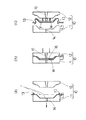
このオーバーレイ成形の従来方法は、図3(a)に示すように、熱可塑性樹脂フィルムFを凹型11と凸型12との間に介在させてフィルムクランプ13で凹型11に固定した状態で、当該フィルムFを加熱軟化させると共に、凹型11の内外に通ずる小孔14から凹型11内の空気をバキュームで抜いて、軟化したフィルム1を真空成形法により凹型11の内面に沿って密着させた形態にセットする。
【0003】次いで、図3(b)に示すように、凹型11及び凸型12の合わせ面を前記熱可塑性樹脂フィルムFの余剰部を両側から挟み付けるように合わせて型締めし、内面に前記フィルムFが密着していない凸型12に穿設された湯道15を通じてその湯口からキャビティ16内に成形材料となる溶融樹脂を射出圧入し、これを冷却固化することにより、プラスチック成形品Wの成形加工と表面加工を同時に行うようにしている。
【0004】この溶融樹脂がキャビティ16内で冷却固化してプラスチック成形品Wの射出成形が完了し、その表面に表皮材となる熱可塑性樹脂フィルムFを上張りするオーバーレイ成形も完了すると、金型10を図3(c)の如く型開きしてプラスチック成形品Wを取り出し、当該成形品Wの周縁部からはみ出したフィルムFの余剰部を切除するトリミング作業を行う。
【0005】
【発明が解決しようとする課題】
ところで、金型10を型開きするときは、図3(c)に示すように、プラスチック成形品Wは湯道15が形成された凸型12側に残った状態で取り出されることになるが、このときに、成形品Wの周縁部にはみ出したフィルムFの余剰部が凹型11のフィルムクランプ13で成形品Wの表面から剥れる方向に引っ張られるので、成形品Wの周縁部でフィルムFが破れて製品不良を生ずるという問題があった。
【0006】そこで本発明は、型開きするときにフィルムが成形品の表面から剥がれる方向に引っ張られても成形品の周縁部でフィルムが破断することがないようにすることを技術的課題としている。
【0007】
【課題を解決するための手段】
この課題を解決するために、本発明は、プラスチック成形品の表皮材となる熱可塑性樹脂フィルムを凹型又は凸型のいずれか一方の型の内面に密着させるように予めセットした状態で、凹型及び凸型の合わせ面が前記熱可塑製樹脂フィルムの余剰部分を両側から挟み付けるように合わされて型締めされ、内面に前記フィルムが密着していない他方の型に穿設された湯道を通じてその湯口からキャビティ内に成形材料となる溶融樹脂が射出圧入される射出成形金型において、前記他方の型に、キャビティ内に湯口を開口した主湯道と、当該主湯道に連通せられて前記フィルムの余剰部を挟み付ける前記合わせ面に湯口を開口した副湯道が穿設されていることを特徴とする。
【0008】本発明によれば、フィルムが密着されていない方の型に、キャビティ内に湯口を開口した主湯道と、当該主湯道に連通して形成せられて前記フィルムの余剰部を挟み付ける合わせ面に湯口を開口した副湯道が穿設されているので、前記副湯道へ圧入される溶融樹脂をその湯口から前記フィルムの余剰部表面に供給して冷却固化させることにより、その余剰部表面に固着されたダミーランナが形成される。
そして、これを型開きするときに、フィルムが成形品の表面から剥される方向に引っ張られても、そのフィルムはダミーランナの部分で破断することとなり、したがって、少なくともフィルムが破断しやすい部分にダミーランナを形成しておけば、型開きのときにフィルムが成形品の周縁部で破断する製品不良を生じない。
【0009】
【発明の実施の形態】
以下、本発明の実施の形態を図面に基づいて具体的に説明する。
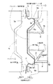
図1は本発明に係る射出成形金型を示す断面図、図2は本発明方法で形成されたプラスチック成形品を示す図である。
【0010】本例に係る射出成形金型1は、型締めしたときにその内部に所定形状のキャビティ2が形成される左右一対の凹型3と凸型4とからなり、プラスチック成形品Wの表皮材となる熱可塑性樹脂フィルムFを凹型3の表面にフィルムクランプ5で固定し、これを加熱軟化させると共に凹型3内の空気をバキュームで抜いてその内面に密着させるように予めセットした状態で、凹型3及び凸型4の合わせ面3a,4aが前記熱可塑性樹脂フィルムFの余剰部分を両側から挟み付けるように合わされて型締めされるように形成されている。
【0011】また、凸型4には、キャビティ2内に湯口6aを開口した複数の主湯道6,6と、当該主湯道6に連通せられて前記フィルムFの余剰部を挟み付ける前記合わせ面3aに湯口7aを開口した複数の副湯道7が穿設されると共に、背面側に射出ノズル(図示せず)を装着するスプルーブシュ8aを開口した注入湯道8が形成され、当該注入湯道8が一の副湯道7に連通されている。
また、副湯道7は、その湯口7aから主湯道6に向かって直線的に、且つ、その内径が徐々に細くなるように形成されると共に、主湯道6との合流点7bが最も細く形成され、溶融樹脂が冷却固化したときに僅かな力が加わるだけでその合流点7vで折れるように成されている。
【0012】
以上が本発明に係る射出成形金型の一例構成であって、次にこれを用いた射出成形方法について説明する。
まず、プラスチック成形品Wの表皮材となる熱可塑性樹脂フィルムFをフィルムクランプ5で固定し、凹型3の内面に密着させるように予めセットした状態で、凹型3及び凸型4の合わせ面3a,4aを前記熱可塑性樹脂フィルムFの余剰部を両側から挟み付けるように合わせて型締めする。
そして、凸型4の注入湯道8に形成されたスプルーブシュ8aから成形材料となる溶融樹脂を射出圧入する。
このとき、溶融樹脂は、一の副湯道7の湯口7aから前記フィルムFの余剰部表面に供給されると共に、当該副湯道7を介してこれに連通した主湯道6内に圧入され、その湯口6aからキャビティ2内に射出圧入される。
そして、キャビティ2を介して他の主湯道6の湯口6aからこれに連通する他の副湯道7に圧入されて、その湯口7aから前記フィルムFの余剰部表面に供給される。
そして、この溶融樹脂が冷却固化すると、キャビティ2内で表面にフィルムFが上張りされたプラスチック成形品が成形されると共に、当該フィルムFの余剰部表面にダミーランナDが固着形成される。
【0013】
ここで、凹型3と凸型4を型開きすると、プラスチック成形品Wは各湯道6,7が形成されている凸型4側に残った状態で取り出される。このときに、成形品Wの周縁部にはみ出したフィルムFの余剰部が凹型3のフィルムクランプ5で引っ張られるが、成形品Wの余剰部表面にはダミーランナDが形成されいてるので、フィルムFが破断するとしてもそのダミーランナDの部分で破断し、成形品Wの周縁部で破断することはない。
そして、副湯道7は、主湯道6に向かって直線的に、且つ、その内径が徐々に細くなるように形成されると共に、主湯道6との合流点7bが最も細く形成されており、その合流点7bに作用する僅かな力で副湯道7内に形成されたダミーランナDと主湯道6内で形成されたランナの接続部が折れて分離されるので、凸型4からプラスチック成形品Wを取り出す際に何ら支障となることはない。
【0014】
なお、上述の説明では、注入湯道8を一の副湯道7に連通した場合について説明したが、本発明はこれに限らず主湯道6に連通させる場合であってもよい。
【0015】
【発明の効果】
以上述べたように、本発明によれば、プラスチック成形品の表皮材となる熱可塑性樹脂フィルムの余剰部表面にダミーランナが形成されるので、型開きするときにフィルムが成形品の表面から剥がれる方向に引っ張られて破断することがあっても、当該フィルムはダミーランナの部分で破断するので、成形品の周縁部でフィルムが破断する製品不良を起こすことがなく、生産効率が向上するという大変優れた効果を奏する。
【図面の簡単な説明】
【図1】本発明に係る射出成形金型を示す断面図。
【図2】本発明方法で形成されたプラスチック成形品を示す図。
【図3】(a)〜(c)は従来のオーバーレイ成形方法を示す説明図。
【符号の説明】
1・・・・・射出成形金型
2・・・・・キャビティ
3・・・・・凹型
4・・・・・凸型
3a,4a・合わせ面
W・・・・・プラスチック成形品
F・・・・・熱可塑性樹脂フィルム
6・・・・・主湯道
6a・・・・湯口
7・・・・・副湯道
7a・・・・湯口[0001]
[Prior art]
The present invention relates to an injection mold in which a thermoplastic resin film is overlaid on the surface of a plastic molded article and an overlay molding method using the same.
[0002]
[Prior art]
In order to bring out a high-class appearance, plastic molded products such as instrument panels that are installed in the interior of automobiles are molded into the injection mold when molded with molding materials such as ABS resin and polycarbonate. Overlay molding is performed in which a thermoplastic resin film on which a pattern or the like is printed is set in advance, and this is overlaid on the surface of a part molded in a mold.
As shown in FIG. 3 (a), the conventional method of overlay molding is such that the thermoplastic resin film F is interposed between the concave mold 11 and the convex mold 12 and fixed to the concave mold 11 with a film clamp 13. The film F is heated and softened, and the air in the concave mold 11 is vacuumed from the small holes 14 communicating with the inside and outside of the concave mold 11 so that the softened film 1 is brought into close contact with the inner surface of the concave mold 11 by vacuum forming. set.
Next, as shown in FIG. 3 (b), the mating surfaces of the concave mold 11 and the convex mold 12 are matched and clamped so that the excess portion of the thermoplastic resin film F is sandwiched from both sides, and the inner surface is clamped. A molten resin as a molding material is injected and injected into the cavity 16 from the gate through the runner 15 formed in the convex mold 12 to which the film F is not in close contact, and is cooled and solidified. Molding and surface processing are performed at the same time.
When the molten resin is cooled and solidified in the cavity 16 to complete the injection molding of the plastic molded product W, and the overlay molding for overlaying the thermoplastic resin film F as the skin material on the surface is completed, the mold is completed. The mold 10 is opened as shown in FIG. 3C, the plastic molded product W is taken out, and a trimming operation for cutting off the excess portion of the film F protruding from the peripheral edge of the molded product W is performed.
[0005]
[Problems to be solved by the invention]
By the way, when the mold 10 is opened, as shown in FIG. 3C, the plastic molded product W is taken out while remaining on the convex mold 12 side where the runner 15 is formed. At this time, since the surplus portion of the film F that protrudes from the peripheral edge of the molded product W is pulled in the direction of peeling from the surface of the molded product W by the film clamp 13 of the concave mold 11, the film F is formed at the peripheral edge of the molded product W. There was a problem that it broke and caused product defects.
Therefore, the present invention has a technical problem to prevent the film from being broken at the periphery of the molded product even when the film is pulled in the direction of peeling from the surface of the molded product when the mold is opened. .
[0007]
[Means for Solving the Problems]
In order to solve this problem, in the present invention, in a state where the thermoplastic resin film as the skin material of the plastic molded product is set in advance so as to be in close contact with the inner surface of either the concave mold or the convex mold, The mating surface of the convex mold is fitted and clamped so that the excess portion of the thermoplastic resin film is sandwiched from both sides, and the sprue is formed through a runner drilled in the other mold where the film does not adhere to the inner surface. In the injection mold in which a molten resin as a molding material is injected and injected into the cavity from the main mold with the other mold connected to the main runner with an opening in the cavity, and the film connected to the main runner A secondary runner having a gate is opened in the mating surface that sandwiches the surplus portion.
According to the present invention, the mold having no film adhered thereto is provided with a main runner having a gate open in the cavity, and an excess portion of the film formed in communication with the main runner. Since a secondary runner opening a sprue is formed in the mating surface to be sandwiched, by supplying the molten resin press-fitted into the secondary runner from the sprue to the surplus portion surface of the film, cooling and solidifying, A dummy runner fixed to the surplus portion surface is formed.
When the mold is opened, even if the film is pulled in the direction in which the film is peeled off from the surface of the molded product, the film is broken at the dummy runner portion. If the film is formed, there will be no product defect in which the film breaks at the periphery of the molded product when the mold is opened.
[0009]
DETAILED DESCRIPTION OF THE INVENTION
Hereinafter, embodiments of the present invention will be described in detail with reference to the drawings.
FIG. 1 is a cross-sectional view showing an injection mold according to the present invention, and FIG. 2 is a view showing a plastic molded product formed by the method of the present invention.
An injection mold 1 according to the present embodiment comprises a pair of left and right concave molds 3 and convex molds 4 in which a cavity 2 having a predetermined shape is formed when the mold is clamped. In a state where the thermoplastic resin film F as a material is fixed to the surface of the concave mold 3 with a film clamp 5 and is preliminarily set so as to heat and soften it and to draw out the air in the concave mold 3 by vacuuming and closely contacting the inner surface thereof. The mating surfaces 3a and 4a of the concave mold 3 and the convex mold 4 are formed so as to be fitted and clamped so as to sandwich the excess portion of the thermoplastic resin film F from both sides.
The convex mold 4 has a plurality of main runners 6 and 6 having a gate 6a opened in the cavity 2 and the surplus portion of the film F sandwiched between the main runners 6 and the main runner 6. A plurality of secondary runners 7 having a spout 7a opened on the mating surface 3a are formed, and an injection runner 8 having an open sprue bush 8a for mounting an injection nozzle (not shown) is formed on the back side. The injection runner 8 communicates with the one secondary runner 7.
The secondary runner 7 is formed linearly from the gate 7a toward the main runner 6 so that the inner diameter gradually decreases, and the junction 7b with the main runner 6 is the most. When the molten resin is cooled and solidified, it is formed so as to be broken at the junction 7v only by applying a slight force.
[0012]
The above is an example configuration of the injection mold according to the present invention. Next, an injection molding method using the mold will be described.
First, the thermoplastic resin film F, which is the skin material of the plastic molded product W, is fixed with the film clamp 5 and set in advance so as to be in close contact with the inner surface of the concave mold 3. 4a is clamped in such a way that the excess part of the thermoplastic resin film F is sandwiched from both sides.
Then, a molten resin as a molding material is injected and injected from a sprue bush 8 a formed in the pouring channel 8 of the convex mold 4.
At this time, the molten resin is supplied to the surplus portion surface of the film F from the sprue 7a of the one secondary runner 7 and is press-fitted into the main runner 6 communicating therewith via the secondary runner 7. The injection hole 6a is injected into the cavity 2.
Then, it is press-fitted from the sprue 6a of the other main runner 6 through the cavity 2 to another sub runner 7 communicating therewith, and is supplied to the surplus portion surface of the film F from the sprue 7a.
When the molten resin is cooled and solidified, a plastic molded product having the film F overlaid on the surface is formed in the cavity 2, and the dummy runner D is fixedly formed on the surplus surface of the film F.
[0013]
Here, when the concave mold 3 and the convex mold 4 are opened, the plastic molded product W is taken out while remaining on the convex mold 4 side where the runners 6 and 7 are formed. At this time, the surplus portion of the film F that protrudes from the peripheral portion of the molded product W is pulled by the film clamp 5 of the concave mold 3, but the dummy runner D is formed on the surplus portion surface of the molded product W. Even if it breaks, it breaks at the dummy runner D and does not break at the peripheral edge of the molded product W.
The secondary runner 7 is formed linearly toward the main runner 6 so that its inner diameter gradually decreases, and the junction 7b with the main runner 6 is formed the thinnest. The connecting portion between the dummy runner D formed in the sub runner 7 and the runner formed in the main runner 6 is broken and separated by a slight force acting on the junction 7b. There is no hindrance when taking out the plastic molded product W.
[0014]
In the above description, the case where the injection runner 8 communicates with one sub runner 7 has been described. However, the present invention is not limited to this, and the case where the injection runner 8 communicates with the main runner 6 may be used.
[0015]
【The invention's effect】
As described above, according to the present invention, since the dummy runner is formed on the surface of the surplus portion of the thermoplastic resin film that becomes the skin material of the plastic molded product, the direction in which the film is peeled off from the surface of the molded product when the mold is opened. Even if the film is broken by being pulled by the film, the film breaks at the dummy runner part, so that the film breaks at the peripheral part of the molded product without causing a product failure, and the production efficiency is improved. There is an effect.
[Brief description of the drawings]
FIG. 1 is a cross-sectional view showing an injection mold according to the present invention.
FIG. 2 is a view showing a plastic molded article formed by the method of the present invention.
FIGS. 3A to 3C are explanatory views showing a conventional overlay molding method. FIGS.
[Explanation of symbols]
DESCRIPTION OF SYMBOLS 1 ... Injection molding die 2 ... Cavity 3 ... Concave die 4 ... Convex die 3a, 4a, Mating surface W ... Plastic molding F ... ... Thermoplastic resin film 6 ... Main runner 6a ... Tuyu 7 ... Second runner 7a ... Tupo