JP3625525B2 - Flat cable terminal forming method - Google Patents
Flat cable terminal forming method Download PDFInfo
- Publication number
- JP3625525B2 JP3625525B2 JP14317595A JP14317595A JP3625525B2 JP 3625525 B2 JP3625525 B2 JP 3625525B2 JP 14317595 A JP14317595 A JP 14317595A JP 14317595 A JP14317595 A JP 14317595A JP 3625525 B2 JP3625525 B2 JP 3625525B2
- Authority
- JP
- Japan
- Prior art keywords
- conductor
- flat cable
- cut
- longitudinal direction
- exposed portion
- Prior art date
- Legal status (The legal status is an assumption and is not a legal conclusion. Google has not performed a legal analysis and makes no representation as to the accuracy of the status listed.)
- Expired - Lifetime
Links
Images


Landscapes
- Coupling Device And Connection With Printed Circuit (AREA)
- Multi-Conductor Connections (AREA)
Description
【0001】
【産業上の利用分野】
本発明は、フラットケーブルの端末部形成方法に関するものである。
【0002】
【従来の技術】
従来、フラットケーブルの導体の端末部と撚り電線等の導体の端末部の接続は、互いに柔らかい素材の端末部であり、互いに直接接続するには不安定要素を多分に含んでいるため、次に例示するような比較的固い中継導電材を介して接続していた。
【0003】
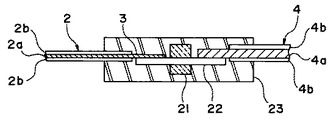
例えば、図3は、フラットケーブル2と撚り電線4とを中継導電材22を介して接続する場合であり、アルミや銅等の導電性の板で形成された中継導電材22の一端に、フラットケーブル2の端末部の絶縁被覆材2bを剥離加工して露出した導体2aを接続し、また中継導電材22の他端に、撚り電線4の絶縁被覆材4bを剥離加工して露出した導体4aを接続したものである。
フラットケーブル2の導体2aや撚り電線4の導体4aは通常複数であるので、中継導電材22も複数個並列に並べられて絶縁樹脂で形成された連結部材21によって、一体に固定されている。
【0004】
また、この接続箇所全体を不慮の外力等から保護するために樹脂ケースや樹脂モールド等の保護部材23で覆っている。
【0005】
図4は、図3に示した撚り電線4に代えて、L字型の端子7を使用した場合であり、L字型の端子7は、中継導電材22の他端に溶接や圧着等で接続されている。なお、図4において、図3と同一部分には同一符号を付して説明を省略する。
【0006】
【発明が解決しようとする課題】
しかしながら、上記のように中継導電材を使用してフラットケーブルと撚り電線等を接続すると、中継導電材という接続部品が必要となり、直接的な接続に比べて部品点数および接続に伴う加工工数が増えるため、部品費や加工費が嵩み、製品のコスト高につながるという問題があった。
【0007】
【発明の目的】
本発明は、かかる点に鑑みてなされたものであり、部品点数を削減し、より生産効率を向上させた安価なフラットケーブルの端末部形成方法を提供することを目的としている。
【0008】
【課題を解決するための手段】
請求項1に係る発明は、フラットケーブルの長手方向に導体露出部を設け、次に該導体露出部の導体に、導体露出部の長手方向のほぼ中央部でフラットケーブルを切断した際に該切断した導体露出部の導体にそれぞれ他の導体が接続されているように他の導体を接続し、しかる後、導体露出部の長手方向のほぼ中央部でフラットケーブルを切断することを特徴とするフラットケーブルの端末部形成方法である。
【0009】
また請求項2に係る発明は、フラットケーブルの長手方向に導体露出部を設け、次に該導体露出部の一面側に補強板を取付け、次に導体露出部の導体に、導体露出部の長手方向のほぼ中央部でフラットケーブルを切断した際に該切断した導体露出部の導体にそれぞれ他の導体が接続されているように他の導体を接続し、しかる後、導体露出部の長手方向のほぼ中央部でフラットケーブルを切断することを特徴とするフラットケーブルの端末部形成方法である。
【0010】
【作用】
請求項1のように、フラットケーブルの長手方向に導体露出部を設け、次に該導体露出部の導体に、導体露出部の長手方向のほぼ中央部でフラットケーブルを切断した際に該切断された導体露出部の導体にそれぞれ他の導体が接続されているように他の導体を接続すると、導体露出部の長手方向のほぼ中央部でフラットケーブルを切断した際には、2個のフラットケーブルの端末部を同時に得ることができる。
【0011】
また、請求項2のように、フラットケーブルの長手方向に導体露出部を設け、次に該導体露出部の一面側に補強板を取付けると、フラットケーブルの導体露出部の強度が向上するために該導体に直接他の導体を接続する作業が容易となる。また、前記導体露出部の導体に、導体露出部の長手方向のほぼ中央部でフラットケーブルを切断した際に該切断された導体露出部の導体にそれぞれ他の導体が接続されているように他の導体を接続すると、導体露出部の長手方向のほぼ中央部でフラットケーブルを切断した際には、2個のフラットケーブルの端末部を同時に得ることができる。
【0012】
【実施例】
以下に本発明を実施例により詳細に説明する。
(実施例1)
図1は本発明の一実施例を示すもので、(a)は縦断面図、(b)は(a)を切り離した状態の縦断面図である。
本発明のフラットケーブルの端末部形成方法においては、まず、フラットケーブル2の長手方向の所定位置において、絶縁被覆材2bを剥離して導体2aを露出し、導体露出部1を設ける。実施例いおいては、導体2aの両面の絶縁被覆材2bを剥離して導体露出部1を設けている。
【0013】
次に、該露出した導体2aの上面側に、撚り電線4を接続する。すなわち撚り電線4はその絶縁被覆材4bを剥離して導体4aを露出し、該露出した導体4aをフラットケーブル2の導体2aに半田等で接続することにより両者を接続する。実施例においては、撚り電線4は、2本使用されており、それぞれがフラットケーブル2の長手方向に沿って配置されている。該フラットケーブル2の長手方向に沿って配置された2本の撚り電線4はその導体4aがフラットケーブル2の導体2aの両側にそれぞれ接続されている。撚り電線4の導体4aをフラットケーブル2の導体2aに接続する位置は、導体露出部1の長手方向のほぼ中央部でフラットケーブルを切断した際に該切断した導体露出部1の導体にそれぞれ他の導体が接続されているような位置である。
【0014】
最後に、フラットケーブル2の導体露出部1の長手方向のほぼ中央部すなわち、A−A線部でフラットケーブル2を切断する。これによって、図1(b)に示すようなフラットケーブルの端末部を2個同時に得ることができる。
【0015】
なお、フラットケーブルの導体を露出する際には、一面側の絶縁被覆材のみを剥離し、他方側の絶縁被覆材は残しておいてもよい。このように構成すると、導体露出部の導体の強度を向上させることができるので、該位置に他の導体を接続する作業が容易になる。
また、A−A線部でフラットケーブル2を切断する際には、切断部分に沿え板(図示せず)を配置し、該沿え板と共にフラットケーブルを切断するようにすると、切断が容易となる。
更に、フラットケーブルの導体と撚り電線の導体とを接続する際には、撚り電線がフラットケーブル上を動かないように、撚り電線を接着材等でフラットケーブルに固定しておくことが好ましい。
更に、フラットケーブル2の導体2aに接続する他の導体は撚り電線でなく端子であってもよい。
更に、実施例においては、フラットケーブルの導体と撚り電線の導体の接続部を1箇所示してあるが、このような接続部は通常並列して複数箇所存在しているものである。
【0016】
(実施例2)
図2は本発明の他の実施例を示すもので、(a)平面図、(b)は側面図、(c)は端子を接続した状態の側面図である。
本発明においては、まず図2(a)(b)に示すように、フラットケーブル2の長手方向の所定位置において、絶縁被覆材2bを剥離して導体2aを露出し、導体露出部1を設ける。実施例においては片面側のみの絶縁被覆材2bを剥離して導体露出部1を設けてある。
【0017】
次に、該導体露出部1の一面側に補強板10を取付ける。この補強板10は導体露出部1の絶縁被覆材2bを剥離してない側の絶縁被覆材2b上に設けてある。
【0018】
次に導体2aにそれぞれL字型の端子7を接続する。L字型の端子7をフラットケーブル2の導体2aに接続する位置は、導体露出部1の長手方向のほぼ中央部でフラットケーブル2を切断した際、該切断した導体露出部1の導体にそれぞれL字型の端子が接続されるような位置である。
最後に、フラットケーブル2の導体露出部1の長手方向のほぼ中央部でフラットケーブル2を切断する。これによって、L字型の端子7が付いたフラットケーブルの端末部を2個の同時に得ることができる。
【0019】
なお、L字型の端子7を導体2aに接続する前に、図2(b)に示すように導体2aを所定長L切断しておいてもよい。このように導体2aを所定長L切断しておくと、導体露出部1の強度が若干落ちるが、補強板10があることから、L字型の端子7の接続に問題はなく、またフラットケーブル2の導体露出部1の長手方向のほぼ中央部でフラットケーブル2を切断した際に、フラットケーブル2の導体2aが端子7の端部から長く露出しなくなるという利点がある。
また、端子の形状はL字型に限られるものではなく、例えば雌型の端子であってもよい。
更に、端子に代えて撚り電線を使用してもよい。
更に、フラットケーブル2の絶縁被覆材2bは導体2aの両側を剥離してもよい。
更に、フラットケーブルを切断する際には、切断部分に沿え板を配置し、該沿え板と共にフラットケーブルを切断するようにしてもよい点は前記実施例を同様である。
【0020】
【発明の効果】
以上、説明した如く、請求項1の発明であるフラットケーブルの端末部形成方法によれば、従来必要であった中継導電材を介さずにフラットケーブルの導体端末と他の導体を容易に接続することができるため、部品点数が削減できるとともに、一度に2個の端末部を得ることができるから、生産効率が向上し、より安価なフラットケーブルの端末部を得ることができる。
また、請求項2の発明であるフラットケーブルの端末部形成方法によれば、前述した請求項1の発明の効果に加え、フラットケーブルの導体露出部の強度が向上するために該導体に直接他の導体を接続する作業が容易となる。
【図面の簡単な説明】
【図1】図1は本発明の一実施例を示すもので、(a)は縦断面図、(b)は(a)を切り離した状態の縦断面図である。
【図2】図2は本発明の他の実施例を示すもので、(a)は平面図、(b)は側面図、(c)は端子を接続した状態の側面図である。
【図3】従来の接続構造の一実施例を示す説明図である。
【図4】従来の接続構造の他の実施例を示す説明図である。
【符号の説明】
1 導体露出部
2 フラットケーブル
2a 導体
2b 絶縁被覆材
4a 他の導体
7 L字型の端子
10 補強板[0001]
[Industrial application fields]
The present invention relates to a method for forming a terminal portion of a flat cable.
[0002]
[Prior art]
Conventionally, the connection between the end portion of the conductor of the flat cable and the end portion of the conductor such as the twisted electric wire is a soft end portion of the material, and since it includes many unstable elements to connect directly to each other, The connection is made through a relatively hard relay conductive material as illustrated.
[0003]
For example, FIG. 3 shows a case where the
Since there are usually a plurality of
[0004]
Further, in order to protect the entire connected portion from an unexpected external force or the like, it is covered with a
[0005]
FIG. 4 shows a case where an L-
[0006]
[Problems to be solved by the invention]
However, when connecting a flat cable and a twisted wire using a relay conductive material as described above, a connection component called a relay conductive material is required, and the number of parts and the number of processing steps associated with the connection increase compared to direct connection. For this reason, there is a problem that the parts cost and the processing cost increase and the cost of the product increases.
[0007]
OBJECT OF THE INVENTION
This invention is made | formed in view of this point, and it aims at providing the terminal part formation method of the cheap flat cable which reduced the number of parts and improved the production efficiency more.
[0008]
[Means for Solving the Problems]
According to the first aspect of the present invention, the conductor exposed portion is provided in the longitudinal direction of the flat cable, and then the conductor is exposed when the flat cable is cut at the substantially central portion in the longitudinal direction of the conductor exposed portion. The flat conductor is characterized in that another conductor is connected to the conductor of the exposed conductor portion so that the other conductor is connected to the conductor, and then the flat cable is cut at substantially the center in the longitudinal direction of the exposed conductor portion. This is a method for forming a cable terminal.
[0009]
In the invention according to
[0010]
[Action]
As in claim 1, the conductor exposed portion is provided in the longitudinal direction of the flat cable, and then the conductor is exposed when the flat cable is cut at the substantially central portion in the longitudinal direction of the conductor exposed portion. When other conductors are connected such that other conductors are connected to the conductors of the exposed conductor portions, two flat cables are cut when the flat cable is cut at the substantially central portion in the longitudinal direction of the exposed conductor portions. Can be obtained at the same time.
[0011]
Further, as described in
[0012]
【Example】
Hereinafter, the present invention will be described in detail with reference to examples.
Example 1
1A and 1B show an embodiment of the present invention, in which FIG. 1A is a longitudinal sectional view, and FIG. 1B is a longitudinal sectional view in a state where FIG.
In the flat cable terminal portion forming method of the present invention, first, at a predetermined position in the longitudinal direction of the
[0013]
Next, the twisted
[0014]
Finally, the
[0015]
When exposing the conductor of the flat cable, only the insulation coating material on one side may be peeled off and the insulation coating material on the other side may be left. If comprised in this way, the intensity | strength of the conductor of a conductor exposed part can be improved, Therefore The operation | work which connects another conductor to this position becomes easy.
Further, when the
Furthermore, when connecting the conductor of the flat cable and the conductor of the twisted wire, it is preferable to fix the twisted wire to the flat cable with an adhesive or the like so that the twisted wire does not move on the flat cable.
Furthermore, the other conductor connected to the
Further, in the embodiment, one connection portion of the conductor of the flat cable and the conductor of the stranded wire is shown, but such a connection portion usually exists in parallel at a plurality of locations.
[0016]
(Example 2)
2A and 2B show another embodiment of the present invention, in which FIG. 2A is a plan view, FIG. 2B is a side view, and FIG. 2C is a side view with terminals connected.
In the present invention, first, as shown in FIGS. 2A and 2B, at a predetermined position in the longitudinal direction of the
[0017]
Next, the reinforcing
[0018]
Next, an L-shaped
Finally, the
[0019]
Before connecting the L-shaped
Further, the shape of the terminal is not limited to the L shape, and may be a female terminal, for example.
Furthermore, a twisted electric wire may be used instead of the terminal.
Furthermore, the
Furthermore, when the flat cable is cut, a plate along the cut portion may be arranged, and the flat cable may be cut together with the plate along the same as in the above embodiment.
[0020]
【The invention's effect】
As described above, according to the flat cable terminal portion forming method according to the first aspect of the present invention, the flat cable conductor terminal and other conductors can be easily connected without using the relay conductive material which has been conventionally required. Therefore, since the number of parts can be reduced and two terminal portions can be obtained at a time, the production efficiency can be improved, and a cheaper flat cable terminal portion can be obtained.
According to the flat cable terminal portion forming method of the invention of
[Brief description of the drawings]
1A and 1B show an embodiment of the present invention, in which FIG. 1A is a longitudinal sectional view, and FIG. 1B is a longitudinal sectional view in a state where FIG.
2A and 2B show another embodiment of the present invention, in which FIG. 2A is a plan view, FIG. 2B is a side view, and FIG. 2C is a side view with terminals connected.
FIG. 3 is an explanatory view showing an embodiment of a conventional connection structure.
FIG. 4 is an explanatory view showing another embodiment of a conventional connection structure.
[Explanation of symbols]
DESCRIPTION OF SYMBOLS 1 Conductor exposed
Claims (2)
Priority Applications (1)
| Application Number | Priority Date | Filing Date | Title |
|---|---|---|---|
| JP14317595A JP3625525B2 (en) | 1995-06-09 | 1995-06-09 | Flat cable terminal forming method |
Applications Claiming Priority (1)
| Application Number | Priority Date | Filing Date | Title |
|---|---|---|---|
| JP14317595A JP3625525B2 (en) | 1995-06-09 | 1995-06-09 | Flat cable terminal forming method |
Publications (2)
| Publication Number | Publication Date |
|---|---|
| JPH08339846A JPH08339846A (en) | 1996-12-24 |
| JP3625525B2 true JP3625525B2 (en) | 2005-03-02 |
Family
ID=15332661
Family Applications (1)
| Application Number | Title | Priority Date | Filing Date |
|---|---|---|---|
| JP14317595A Expired - Lifetime JP3625525B2 (en) | 1995-06-09 | 1995-06-09 | Flat cable terminal forming method |
Country Status (1)
| Country | Link |
|---|---|
| JP (1) | JP3625525B2 (en) |
Families Citing this family (1)
| Publication number | Priority date | Publication date | Assignee | Title |
|---|---|---|---|---|
| JP3803897B2 (en) * | 1998-05-06 | 2006-08-02 | アルプス電気株式会社 | Manufacturing method of rotating connector |
-
1995
- 1995-06-09 JP JP14317595A patent/JP3625525B2/en not_active Expired - Lifetime
Also Published As
| Publication number | Publication date |
|---|---|
| JPH08339846A (en) | 1996-12-24 |
Similar Documents
| Publication | Publication Date | Title |
|---|---|---|
| EP0894347B1 (en) | A shielded cable and connector assembly | |
| US6083034A (en) | Connecting structure for coaxial cable connector and method for connecting the same | |
| JPH03236112A (en) | Flat type multiconductor cable and forming method thereof | |
| EP0614247B1 (en) | Electric wire joining method | |
| US4799899A (en) | Connective structure for conductive wires and a method of manufacturing the same | |
| JP3011041B2 (en) | Flat multi-core wire | |
| JP3625525B2 (en) | Flat cable terminal forming method | |
| JP3259219B2 (en) | Signal cable device | |
| JPH034464A (en) | Flat cable connector | |
| JP2003045241A (en) | Shield flat cable and its manufacturing method | |
| JPH05190247A (en) | Method for connecting insulated wire | |
| JP3039281B2 (en) | Wire harness with shield | |
| JP2000152465A (en) | Wire connecting structure | |
| JP2005317473A (en) | Pressure-welded grounding terminal and wire harness using the same | |
| JPH0737437A (en) | Pressure adhering shield wire | |
| JP3049472B2 (en) | Cable track | |
| JP2022118803A (en) | Connection structure between bus bar and cable | |
| JPH069063U (en) | Connection structure of conductors in electrical junction box | |
| JPH01195608A (en) | Shielded flat cable, flat cable for shielded flat cable and manufacture thereof | |
| JPH0311764Y2 (en) | ||
| JP2000323201A (en) | Waterproofing structure of shield wire end portion | |
| JPS5919346Y2 (en) | Branch connection between terminal fitting and electric wire | |
| JPH09115572A (en) | Wiring structure for wire haness branch connection box | |
| JP3098662U (en) | Flat cable | |
| JP2940423B2 (en) | Electrical junction box |
Legal Events
| Date | Code | Title | Description |
|---|---|---|---|
| A977 | Report on retrieval |
Free format text: JAPANESE INTERMEDIATE CODE: A971007 Effective date: 20040816 |
|
| A131 | Notification of reasons for refusal |
Free format text: JAPANESE INTERMEDIATE CODE: A131 Effective date: 20040827 |
|
| A521 | Written amendment |
Free format text: JAPANESE INTERMEDIATE CODE: A523 Effective date: 20041013 |
|
| TRDD | Decision of grant or rejection written | ||
| A01 | Written decision to grant a patent or to grant a registration (utility model) |
Free format text: JAPANESE INTERMEDIATE CODE: A01 Effective date: 20041116 |
|
| A61 | First payment of annual fees (during grant procedure) |
Free format text: JAPANESE INTERMEDIATE CODE: A61 Effective date: 20041130 |
|
| FPAY | Renewal fee payment (event date is renewal date of database) |
Free format text: PAYMENT UNTIL: 20071210 Year of fee payment: 3 |
|
| FPAY | Renewal fee payment (event date is renewal date of database) |
Free format text: PAYMENT UNTIL: 20081210 Year of fee payment: 4 |
|
| FPAY | Renewal fee payment (event date is renewal date of database) |
Free format text: PAYMENT UNTIL: 20081210 Year of fee payment: 4 |
|
| FPAY | Renewal fee payment (event date is renewal date of database) |
Free format text: PAYMENT UNTIL: 20091210 Year of fee payment: 5 |
|
| FPAY | Renewal fee payment (event date is renewal date of database) |
Free format text: PAYMENT UNTIL: 20101210 Year of fee payment: 6 |
|
| FPAY | Renewal fee payment (event date is renewal date of database) |
Free format text: PAYMENT UNTIL: 20101210 Year of fee payment: 6 |
|
| FPAY | Renewal fee payment (event date is renewal date of database) |
Free format text: PAYMENT UNTIL: 20111210 Year of fee payment: 7 |
|
| FPAY | Renewal fee payment (event date is renewal date of database) |
Free format text: PAYMENT UNTIL: 20111210 Year of fee payment: 7 |
|
| FPAY | Renewal fee payment (event date is renewal date of database) |
Free format text: PAYMENT UNTIL: 20121210 Year of fee payment: 8 |
|
| FPAY | Renewal fee payment (event date is renewal date of database) |
Free format text: PAYMENT UNTIL: 20121210 Year of fee payment: 8 |
|
| FPAY | Renewal fee payment (event date is renewal date of database) |
Free format text: PAYMENT UNTIL: 20131210 Year of fee payment: 9 |
|
| EXPY | Cancellation because of completion of term |