JP3624768B2 - Parallel parking assistance device - Google Patents
Parallel parking assistance device Download PDFInfo
- Publication number
- JP3624768B2 JP3624768B2 JP36745699A JP36745699A JP3624768B2 JP 3624768 B2 JP3624768 B2 JP 3624768B2 JP 36745699 A JP36745699 A JP 36745699A JP 36745699 A JP36745699 A JP 36745699A JP 3624768 B2 JP3624768 B2 JP 3624768B2
- Authority
- JP
- Japan
- Prior art keywords
- vehicle
- steering
- target point
- parallel parking
- point
- Prior art date
- Legal status (The legal status is an assumption and is not a legal conclusion. Google has not performed a legal analysis and makes no representation as to the accuracy of the status listed.)
- Expired - Fee Related
Links
Images


Landscapes
- Traffic Control Systems (AREA)
- Steering Control In Accordance With Driving Conditions (AREA)
- Image Processing (AREA)
- Closed-Circuit Television Systems (AREA)
Description
【0001】
【発明の属する技術分野】
この発明は、縦列駐車支援装置に係り、特に画像処理により目標となる駐車枠を認識する装置に関する。
【0002】
【従来の技術】
従来、車両の後進時に運転者が車両の死角により目標とする場所が見えなくなった場合に、モニタに車両の後方視界を写し出すようにした装置が提案されている。例えば、特公平2−36417号公報には、車両後方を撮影するテレビカメラと、このテレビカメラのとらえた映像を写し出すモニタテレビと、タイヤ操舵角に係る情報信号を出力するセンサと、このセンサからの情報信号に応じてマーカー信号を発生し、テレビ画面上にマーカーを重畳表示させる回路とからなる車両の後方監視モニタ装置が開示されている。この装置では、タイヤの操舵角データとその操舵角に対応する車両の後進方向に沿ったマーカー位置データがROMに蓄積されており、そのときの操舵角に応じた車両の予想後進軌跡がマーカーの列としてテレビ画面上にテレビカメラで撮影された映像に重畳して表示される。
【0003】
このような装置によれば、車両の後進時に後方の道路の状況等の視界と共に操舵角に応じた車両の予想後進軌跡がモニタテレビの画面上に表示されるため、運転者は、後方を振り向くことなくテレビ画面を見たままでハンドルを操作して車両を後退させることができる。
【0004】
【発明が解決しようとする課題】
縦列駐車する場合には、例えば道路と平行に車両を後退させ、適当な位置でハンドルを切って駐車スペースへ進入し、さらにハンドルを逆方向へ切り返して目標とする駐車位置へ車両を誘導する必要がある。しかしながら、従来の後方監視モニタ装置では、運転者はテレビ画面上で後方の視界と車両の予想後進軌跡とを見ただけでは、どこでハンドルを切り始めたり、切り返せばよいのか、また操舵量をどの程度にすればよいのか判断し難く、縦列駐車の十分な支援を行うことができないという問題点があった。
この発明はこのような問題点を解消するためになされたもので、運転者が縦列駐車する際の操舵のタイミングと操舵量とを容易に把握することができる縦列駐車支援装置を提供することを目的とする。
【0005】
【課題を解決するための手段】
この発明の請求項1に係る縦列駐車支援装置は、車両の後方を撮影するカメラと、車両の運転席に配置され且つ車両の後退時にカメラによる映像を表示するモニタと、ハンドルの操舵角を検出するステアリングセンサと、縦列駐車時に車両の運転を支援するためのガイド表示をモニタの画面上に重畳表示するスーパーインポーズ部と、カメラによる映像を画像処理することにより駐車枠に含まれる2本の直線を認識してそれらの交点を目標点とし、車両の後退に伴う映像の移動に応じて目標点を追跡し、目標点とガイド表示との位置関係に基づいて縦列駐車するために必要な操舵のタイミングと操舵量とを出力する画像処理部とを備えたものである。
【0006】
請求項2に係る縦列駐車支援装置は、請求項1の装置において、画像処理部が、車両の後退に伴う目標点の動きが大きくずれた場合に目標点の位置を予測して修正するものである。
【0007】
請求項3に係る縦列駐車支援装置は、請求項1または2の装置において、画像処理部から出力された操舵のタイミングと操舵量とに対応した音声を発して運転者に操舵の案内を行う音声選択部をさらに備えたものである。
請求項4に係る縦列駐車支援装置は、請求項3の装置において、画像処理部が、操舵のタイミングと操舵量を音声選択部と共にスーパーインポーズ部にも出力して操舵の案内に対応した表示をモニタの画面上に行わせるものである。
請求項5に係る縦列駐車支援装置は、請求項1〜4のいずれか一項の装置において、車両の運転席に配置された縦列駐車モードスイッチをさらに備え、縦列駐車モードスイッチを投入したときにスーパーインポーズ部によりモニタの画面上にガイド表示が表示されるものである。
また、請求項6に係る縦列駐車支援装置は、車両の後方を撮影するカメラと、車両の運転席に配置され且つ車両の後退時にカメラによる映像を表示するモニタと、ハンドルの操舵角を検出するステアリングセンサと、縦列駐車時に車両の運転を支援するためのガイド表示をモニタの画面上に重畳表示するスーパーインポーズ部と、カメラによる映像を画像処理して駐車のための目標点を認識すると共に目標点とガイド表示との位置関係に基づいて縦列駐車するために必要な操舵のタイミングと操舵量とを出力する画像処理部とを備え、ガイド表示は、ステアリングセンサで検出されたハンドルの操舵角に応じてモニタの画面上に移動表示されるハンドルマークを含み、駐車のための停止位置からモニタの画面上においてハンドルマークと駐車のための目標点とが一致するまでハンドルを操作した状態で車両を後退させ、その後ハンドルを反対方向にいっぱい切って後退することにより縦列駐車を行うものである。
さらに、請求項7に係る縦列駐車支援装置は、請求項6の装置において、ガイド表示は、車両に対して特定の位置に固定表示されるアイマークを含み、このアイマークは、モニタの画面上においてハンドルマークと駐車のための目標点とが一致するまでハンドルを操作した状態で車両を後退させたときに、駐車のための目標点がアイマークと一致することにより車両のハンドルを反対方向にいっぱい切る位置への到達を示すものである。
【0008】
請求項1に記載の縦列駐車支援装置では、画像処理部が、駐車枠に含まれる2本の直線の交点を目標点として求め、車両の後退に伴ってこの目標点を追跡し、この目標点とスーパーインポーズ部によってモニタの画面上に重畳表示されたガイド表示との位置関係に基づいて縦列駐車に必要な操舵のタイミングと操舵量とを出力する。
請求項2に記載の縦列駐車支援装置では、請求項1の装置において、画像処理部が、目標点の動きが大きくずれたときに目標点の位置を予測して修正する。
請求項3に記載の縦列駐車支援装置では、請求項1または2の装置において、音声選択部が画像処理部から出力された操舵のタイミングと操舵量とに対応した音声を発して操舵の案内を行う。
請求項4に記載の縦列駐車支援装置では、請求項3の装置において、画像処理部が、操舵のタイミングと操舵量をスーパーインポーズ部にも出力して操舵の案内に対応した表示をモニタの画面上に行わせる。
請求項5に記載の縦列駐車支援装置では、請求項1〜4のいずれか一項の装置において、縦列駐車モードスイッチを投入したときにモニタの画面上にガイド表示が表示される。
請求項6に記載の縦列駐車支援装置では、画像処理部がカメラによる映像を画像処理して駐車のための目標点を認識し、この目標点とスーパーインポーズ部によってモニタの画面上に重畳表示されたガイド表示との位置関係に基づいて縦列駐車に必要な操舵のタイミングと操舵量とを出力し、駐車のための停止位置からモニタの画面上においてハンドルの操舵角に応じて移動表示されたハンドルマークと駐車のための目標点とが一致するまでハンドルを操作した状態で車両を後退させた後ハンドルを反対方向にいっぱい切って後退することにより縦列駐車が行われる。
請求項7に記載の縦列駐車支援装置では、請求項6の装置において、モニタの画面上でハンドルマークと駐車のための目標点とが一致するまでハンドルを操作した状態で車両を後退させたときに、駐車のための目標点がアイマークと一致することにより車両のハンドルを反対方向にいっぱい切る位置への到達が示される。
【0009】
【発明の実施の形態】
以下、この発明の実施の形態を添付図面に基づいて説明する。
実施の形態1.
図1に示されるように、車両1の後部に車両1の後方の視界を撮影するカメラ2が取り付けられている。カメラ2の視界範囲の近接側端部に車両1の後部バンパー3が入っている。車両1の運転席にはカラータイプの液晶ディスプレイからなるモニタ4が配置されており、通常はナビゲーション装置の表示装置として使用され、運転席に設けられたシフトレバー5がR(後退位置)に操作されるとカメラ2による映像が表示されるようになっている。操舵輪としての前輪6はハンドル7の操作により操舵される。
【0010】
図2にモニタ4上の描画の形態を示す。車両1は路側8と平行に停車させる。縦列ガイドライン9はハンドル操作を開始する位置を案内し、これと目標点TPが重なる様に車両1を真直ぐ後退させる。縦列ガイドライン9と目標点TPが重なったら停止し、ハンドル7の操舵量に応じて縦列ガイドライン9上を移動するハンドルマーク10と目標点TPが重なるまでハンドル7を操作する。ハンドルマーク10と目標点TPが重なったらそのままの位置でハンドル7を保持し、アイマーク11と目標点TPが一致するまで後退する。アイマーク11と目標点TPが一致したら、ハンドル7を反対方向にいっぱい切って後退する。後方に注意しながら後退し、車両1が路側8と平行になったところで縦列駐車が完了する。
【0011】
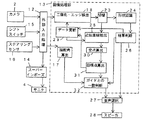
図3にこの発明の実施の形態1に係る縦列駐車支援装置の構成を示す。カメラ2によって撮影された後方映像は外部入力処理部12から画像処理部13とスーパーインポーズ部14へと出力される。スーパーインポーズ部14では図2に示すようなガイド表示をスーパーインポーズし、後方映像と共にモニタ4に出力する。また、外部入力処理部12はシフトスイッチ15からシフトポジションに対応した信号を受け取り、R(後退位置)であればスーパーインポーズ部14に後方映像の表示を指示すると共に画像処理部13に画像処理を行うように信号を出力する。R以外になった時は、これらを停止するように信号を出力する。ステアリングセンサ16はハンドル7を操作した時にパルスを出力する。外部入力処理部12ではこれを受けてカウントし、画像処理部13の操舵角算出部17に出力する。
【0012】
車両1が路側8と平行に駐車した状態からスタートする。停車画像処理部13では、まず、二値化・エッジ検出部18で後方画像を二値化し、エッジの検出を行う。図4に示すように、ほぼ台形状の駐車枠19の縦方向の白線20が縦に横切る位置にヒストグラム領域21を設定し、ヒストグラムを求める。図5に示されるように、得られたヒストグラムの最大濃度レベル側からp%の画素数を初めて超える濃度レベルを二値化の閾値Thとする。二値化は、図6に示されるように、駐車枠19の手前の横方向のラインを含まない、指定された処理領域22のみで行う。二値化された画像から、縦・横方向それぞれのエッジを求め、それらを合成してエッジ画像を得る。図6に示すように限定された処理領域22のみで処理を行うため、画像全体を処理するのに比べて処理が軽くなる。この処理領域22は、縦列駐車を開始する際に駐車枠19が画面の上部に位置することから、図6に示すように画面の上部に設定することができる。
また、図7のように、処理領域22を少なくとも駐車枠19の隅Aが含まれる小さな領域とすることもできる。ただし、車両1の前後位置に拘わらず、横方向の直線の傾きはほぼ一定であるものとする。
【0013】
切替部23ではエッジ画像の出力先の切替えを行う。処理開始から、例えば第1フレームから第10フレームまでは形状認識部24へ出力し、それ以後は近似直線抽出部25へ出力する。形状認識部24は、処理開始時にできるだけ確実に目標点TPの検出を行うためのものであり、駐車枠19の形状を認識して目標点TPを検出する。図8の点P1〜P4の処理領域22内での位置は、路側8からの車両1の距離によって異なる。そこで、予め複数の状態を学習させておき、処理画像がどの状態に近いかを判断することで目標点TPの検出を行なう。
【0014】
次に、具体的な処理について説明する。処理画像は図8に黒線で示されているエッジ部分が白、その他の部分が黒の二値画像である。まず、点P1及びP2を探索する。処理領域22の原点Oから右方向に白画素を探索し、最初に見つけたところを点P1とする。同様に、原点Oから上方向に白画素を探索し、点P2を見つける。路側8からの車両1の距離により、予め点P1及びP2の位置並びに点P1とP3を結んだ直線の傾きm1、点P2とP4を結んだ直線の傾きm2、これら傾きm1とm2の平均mcを求めて例えば図9のように形状No.1〜3として学習させておく。そして、検出された点P1及びP2の位置からどの形状に近いかを判断する。ここでは仮にNo.2の形状とする。
【0015】
次に、点P3及びP4を探索する。まず、点P1と原点Oとの中点をPcとし、そこから傾きM2cの方向に白画素を探していく。白画素を発見したら、その点Pc’のy座標を記憶しておく。点P1から左へ画素数sだけずれた点をP1’とし、そこから傾きM21の方向に白画素を探索して点P3’を求める。同様に、点P2から右へ画素数tだけずれた点P2’から傾きM22の方向に白画素を探索し、点P4’を求める。このとき、点P3’及びP4’のy座標と点Pc’のy座標との差が大きい場合は、何らかのノイズがあったと判断して再び探索を始める。そして、点P3’から右へ画素数sだけずれた点をP3、点P4’から左へ画素数tだけずれた点をP4とする。この処理を10フレーム分繰返す。図10に形状認識部24と結果判断部26のフローチャートを示す。ここで、検出が正常に行われた場合は、各点の座標と、点P1とP3を結ぶ直線の傾きm1、点P3とP4を結ぶ直線の傾きをデータとして出力する。10フレーム分の全ての処理において各点P1〜P4、P1’〜P4’、Pc及びPc’のうち検出できないものがあった場合は、結果判断部26がエラーとしてその旨を音声で案内するための信号を音声選択部27へ出力し、スピーカ28から音声を発する。
【0016】
次に、近似直線抽出部25は、形状認識部24による形状認識処理が全て終了した後、すなわち第11フレーム目以降の画像に対して図11にそのフローチャートを示すような近似直線抽出処理を行う。ここでは、点P1とP3を結ぶ直線L0及び点P3とP4を結ぶ直線L1の近似直線が抽出される。まず、入力されたエッジ画像から輪郭線の抽出を行う。図12に示すように輪郭線の始点SPとなる白画素(例えば濃度レベル255)をスキャンして探索する。始点SPを発見したら、横方向に輪郭線を辿っていく。このとき輪郭線は濃度レベル255以外の値でラベリングされ、輪郭線上の各点に対して、矢印で示されるようにその点より下方に位置する白画素(濃度レベル255)を消去していく。横方向が終わったら、同様に縦方向の輪郭線も濃度レベル255以外の値でラベリングし、輪郭線の右側に位置する白画素を消去する。次に、抽出した輪郭線に対して、処理領域22内の座標系でHough(ハフ)変換により、その輪郭線の近似直線を求める。この後、いま求めた始点SPの位置から再び始点SPの探索を開始するが、輪郭線は濃度レベル255以外の値でラベリングされ、その輪郭線の下及び右側の白画素は消去されているため、このエッジ上の点が始点SPとして検出されることはない。この処理を始点SPの探索位置が処理領域22の右下の隅に来るまで続ける。
【0017】
続いて、Hough変換について説明する。一つの直線は原点からの距離rとx軸からの傾きθを用いて
r=x・sinθ+y・cosθ (1)
で表される。ある直線上の複数の点についてこの(1)式を用いて(r、θ)空間へ写像すると、(r、θ)空間での曲線は一点で交わる。この交点(r、θ)はその直線の傾きと原点からの距離を表す。この性質を用いて、輪郭線上の点を(r、θ)空間へ写像し、(r、θ)空間での曲線の交点を求めることで輪郭線の近似直線のパラメータを求めることができる。
【0018】
実際には、θとrに対応する二次元配列を用意する。これが(r、θ)空間になる。予め、すべての(r、θ)の位置に例えば「0」を入れておき、(1)式でθを変え、そのときのrを求め、その(r、θ)の位置に例えば「1」を加えてカウントしていく。輪郭線上の点全てに対してこの処理を行うと、交点となる(r、θ)の位置のカウント値が他よりも大きくなるため、この点を直線のパラメータとして抽出すればよい。このとき、データ更新部29から前回の近似直線抽出処理において得られた角度を基準角度として受け取り、その角度から前後数度の範囲内で交点を求める。つまり、カウント値が最大となる(r、θ)がその角度範囲内にある時のみ直線のパラメータを抽出する。このようにすることにより、白線の傾きに近いものだけが抽出される。
【0019】
2本の近似直線L0及びL1が抽出されると、交点算出部30では、これら近似直線の交点P(図2の点Aに対応)を算出する。ここでは処理領域22の座標系であるため、全画像の座標系に変換する必要がある。処理領域22の座標系を(x、y)、全画像の座標系を(X、Y)とすると、図13から、関係式
X=spx+x
Y=spy+y
R=X・sinθ+Y・cosθ
r=x・sinθ+y・cosθ
を用いて、交点や直線のパラメータをそれぞれの座標系に変換することができる。交点と直線のデータは目標点算出部31に出力される。もし近似直線が抽出できず、交点が得られなかった場合は、その情報を目標点算出部31に出力する。
【0020】
目標点算出部31では、得られた交点Pから図2に示される目標点TPを算出する。図14(a)に示すように、交点Pから縦方向の近似直線L0上の点POLを求め、これらの点P及びPOLを図14(b)のように路面上に座標変換する。路面上では、点Pから、点Pと点POLとを結ぶ直線に対して直角の方向に駐車枠19の幅Wだけ並行移動した点を目標点TPとして求める。路面上の目標点TPを再び座標変換して図14(a)のように画面上の目標点TPを求める。この処理において、目標点TPが図2の縦列ガイドライン9に重なるまでは点POLは求めずに、交点Pだけを利用して目標点TPを求める。これは、この部分では車両1は路側8と平行であるため、図14(b)の角φが0となるからである。
目標点TPが算出されたら、その座標データをガイドとの一致判断部32へ出力する。さらに、近似直線L0及びL1のパラメータと共にデータ更新部29へも出力される。もし、交点算出部30から交点なしの情報を受けている場合はその情報をデータ更新部29へ出力する。
【0021】
データ更新部29は、過去のデータを記憶しており、交点Pの移動量にしたがって処理領域22の位置とサイズを変更し、二値化・エッジ検出部18に出力する。また、データ更新部29は、近似直線の傾きを近似直線抽出部25に出力する。これは次の直線抽出処理における基準角度となる。目標点算出部31から交点Pが検出されなかった旨の情報を受け取ったときは、各データは更新されずに引き続き使用される。形状認識処理の結果判断部26からは図7の点P1、P3、P4の座標を受け取り、点P1とP3を結ぶ直線の傾き及び点P3とP4を結ぶ直線の傾きを求める。これらの平均値を求めて、近似直線抽出時の基準角度の初期値とする。
【0022】
ガイドとの一致判断部32は、算出された目標点TPと各種ガイドとの距離を求めることにより、目標点TPの各種ガイドへの接近及び一致を判断する。このとき、外部入力処理部12からのカウント値に基づいて操舵角算出部17が操舵角を算出し、ガイドとの一致判断部32は操舵角算出部17から入力した操舵角を用いてハンドルマークの位置を計算する。ハンドル7を操作するとハンドルマーク10が縦列ガイドライン9上を動いて目標点TPに近づいていく。縦列ガイドライン9、アイマーク11については、図15に示されるように、目標点TPがそれぞれに近づいていく。目標点TPと各種ガイドとの距離に応じて音声選択部27に信号を送り、音声選択部27がスピーカ28から対応した音声を出力する。
【0023】
図16に音声ガイドの出力タイミングを示す。(a)は目標点TPが縦列ガイドライン9に重なるまでの状態で、S1、S2、S3の順に目標点TPが縦列ガイドライン9に近づいていき、順次「ポ〜ンポ〜ン」(音1とする)、「ポンポン」(音2とする)、「ポーン」(音3とする)のように、音の高さ及び/または長さを変えて接近の度合いがわかるように出力する。S3では音声ガイドとして「ハンドルマーク(例えば赤色のマーク)が目標点と一致するまでハンドルを回してください」のように、次の操作を案内する音声を出力する。(b)はハンドルマーク10を目標点TPに合わせるまでの状態であり、(a)の場合と同様、S4、S5、S6の順にハンドルマーク10が目標点TPに近づくと、その距離に応じて音1、音2、音3を出力する。S6では「アイマーク(例えば黄色のマーク)が目標点と一致するまで後退して下さい」のように次の操作を案内する音声を出力する。(c)は目標点TPがアイマーク11と一致するまでの状態であり、S7、S8、S9の順にアイマーク11が目標点TPに近づくと、その距離に応じて音1、音2、音3を出力する。S9では「ハンドルを反対方向にいっぱい切ってください」のような案内音声を出力する。(d)ではハンドルを反対方向にある角度以上切ったときに「後方に注意しながら後退して下さい」のような案内音声を出力する。この後、駐車枠19の白線が画面から消えたら「後方車両に注意して車を停止させてください」のような案内音声を出力する。
【0024】
実施の形態2.
この実施の形態2は、例えば縦列ガイドライン9からアイマーク11までの間で、目標点TPを見失ったとしても、ある程度は追跡を続けられるように目標点TPの予測方式を導入したものである。図17に実施の形態2に係る縦列駐車支援装置の構成を示す。この装置は、図3に示した実施の形態1の装置において、画像処理部13に代わりに画像処理部33を外部入力処理部12に接続したものであり、それ以外は実施の形態1の装置と同じである。この画像処理部33は、図3の画像処理部13の交点算出部30と目標点算出部31の代わりに目標点予測部34を設けたものである。図18に目標点予測部33のフローチャートを示す。目標点TPが縦列ガイドライン8と重なり、ハンドルマーク10が目標点TPと一致するまでの処理を前半処理とし、その後、目標点TPがアイマーク11と重なるまでの処理を後半処理とする。前半処理では実施の形態1の装置と同様に交点算出及び目標点算出を行う。後半処理に入ったら、目標点予測に切り替える。
【0025】
次に、目標点予測の原理について説明する。図19において、車両1の旋回中心Cはハンドル7の切れ角によって決まる。点P、目標点TP、縦方向の直線上の点POLは、車両1から見た場合に中心Cの回りを回転運動する。最終的に、目標点TPはアイマークEMに、点Pは仮想アイマークVEMに重なる。これらの点P、TP、POLの回転半径は、それぞれRVEM、REM、RPOLである。図20に点Pの修正と推定方法を示す。路面上で点Pは回転運動をするが、画像から検出された点Pを路面上に変換すると必ずしも円周上には乗らない。(a)では、検出された点Pが円周上から大きく外れた場合の修正法を示している。点Piと中心Cとの距離を求め、REMとの差が大きくなったときは、点Piと中心Cとの距離がREMとなるように修正する。このとき、x軸と線分PiCとの角度θiと角度変化φiを求める。(b)では、点Pが検出されなかった場合の推定方法を示している。過去数回の処理から角度変化の平均値φを求めておく。点Pが検出されなかった場合、角度θ=θi+φ、半径REMで点Pを求める。φは次の角度変化平均を求めるために利用する。点TP及び点POLの角度変化は点Pと同じであるため、点Pを検出・推定した結果得られる角度変化を用いて点TP及び点POLを求める。このとき半径はRVEM及びRPOLである。
【0026】
点Pを修正しない場合は、点POLを修正する必要がある。図21に示すように、点Pの中心Cからの距離DPCは半径REMより大きいが修正しない場合、点Bの位置にある点POLを修正しないと、点Pと点POLとを結ぶ白線L1の傾きに誤差を生じてしまう。そこで、点Pと中心Cとの間の距離DPCの半径REMに対する比率をRPOLに掛けて点POLを修正する。すなわち、△ABCを相似変換する。このようにすることによって、点Pと点POLとを結ぶ直線L2の傾きを点Aと点Bとを結ぶ直線L3の傾きに等しくすることができる。
また、図22に示すように、処理を進めていくと、算出された直線Li−1と白線の傾きがずれていく場合がある。これを吸収するため、ほぼ一定間隔でRVEM、RPOLと角度データを更新する。点Piが検出されたら点POLiを算出し、半径をRVEMi、RPOLiに更新する。このとき、x軸からの角度も更新する。
【0027】
図23に目標点予測のフローチャートを示す。後半処理が始まったら、ハンドルの切れ角から旋回中心C、アイマークの回転半径REMを算出する。続いて点POLを算出し、半径RVEM、RPOL、x軸からの角度を初期値として求める。点Pが検出されており且つデータの更新タイミングであれば、点POLの算出、回転半径RVEM、RPOLの算出及びx軸からの角度データの更新を行う。その後、点Pが検出されていれば、点Pの修正を行い、角度データ(角度変化、x軸からの角度)を更新し、目標点TP及び点POLを算出する。点Pが検出されていないときは、点Pを推定し、角度データ(角度変化は平均の角度変化を採用)を更新し、目標点TP及び点POLを推定する。算出された各点をモニタ4の画面上に変換し、傾きデータを求める。この傾きは直線抽出に利用される。この後、次の点Pの検出処理を行う。
図24(a)は点Pの修正のフローチャートであり、修正をしない場合は回転半径の比rateを求め、点POLの修正に利用する。図24(b)は目標点TP及び点POLの算出のフローチャート、図24(c)は点Pの推定のフローチャートである。
【0028】
実施の形態3.
図25に実施の形態3に係る縦列駐車支援装置の構成を示す。この装置は、図3に示した実施の形態1の装置において、縦列モードスイッチ35を付加的に運転席に設けると共に外部入力処理部12に接続したものである。縦列駐車をする時に運転者が縦列モードスイッチ35を投入して縦列モードに入れる。シフトレバー5をR(後退位置)に操作して縦列モードスイッチ35を投入した時に初めてモニタ4の画面上に縦列ガイドライン9が表示され、画像処理が行われる。すなわち、必要な時に必要なもののみ表示するようにする。また、縦列モードに入ったことを知らせるために、画像処理部13は「縦列駐車モードです」というモード案内音声と、「目標点が青色の線と一致するまで後退して下さい」という操作案内音声を音声選択部27を介してスピーカ28から出力させる。
なお、実施の形態2の装置に縦列モードスイッチ35を接続するようにしてもよい。
【0029】
図26に実施の形態4に係る縦列駐車支援装置の構成を示す。この装置は、図3に示した実施の形態1の装置において、画像処理部13がスーパーインポーズ部14に接続されたものである。画像処理部13のガイドとの一致判断部32から目標点TPと各種ガイドの接近情報をスーパーインポーズ部14に送り、音声選択部27で選択される音声と対応した表示がモニタ4の画面上に行われる。例えば、図27に示されるように、場面の下部に接近表示部36を設け、接近に従って音声が順次音1、音2、音3と変わっていくのに対応して青、黄、赤のように色を順次変えて接近表示部36に表示させる。また、これから運転者がするべき操作ステップを文字表示することもできる。例えば、接近表示部36に重ねて「ガイドライン」、「ハンドルマーク」、「アイマーク」のように、注目しなくてはならないガイドの名前を表示する。
なお、実施の形態2の装置の画像処理部33をスーパーインポーズ部14に接続して、同様に音声と対応した表示をモニタ4の画面上に行うようにしてもよい。
【0030】
【発明の効果】
以上説明したように、請求項1に記載の縦列駐車支援装置によれば、画像処理部が画像処理により駐車のための目標点を認識すると共に目標点とガイド表示との位置関係に基づいて縦列駐車に必要な操舵のタイミングと操舵量とを出力するので、運転者は極めて容易に車両の縦列駐車操作を行うことができる。さらに、画像処理部が、車両の後退に伴って駐車枠に含まれる2本の直線の交点からなる目標点を追跡するので、運転者は車両の後退に従って車両が目標点に至るまでの状況を段階的に把握することができる。
請求項2に記載の縦列駐車支援装置によれば、請求項1の装置において、画像処理部が、目標点の動きが大きくずれたときに目標点の位置を予測して修正するので、目標点を一旦見失ったとしても、ある程度は運転操作の支援を続けることができる。
請求項3に記載の縦列駐車支援装置によれば、請求項1または2の装置において、画像処理部から出力された操舵のタイミングと操舵量とに対応した音声を発して操舵の案内を行うので、運転者はモニタを注視する必要がなく、周囲の安全を確認しながら容易に駐車を行うことができる。
請求項4に記載の縦列駐車支援装置によれば、請求項3の装置において、操舵の案内に対応した表示をモニタの画面上に行わせるので、運転者は目で接近状態を確認することができ、また、文字表示により音声を聞き漏らした場合でも現在の操作ステップを目で確認することができる。
請求項5に記載の縦列駐車支援装置によれば、請求項1〜4のいずれか一項の装置において、縦列駐車モードスイッチを投入したときにモニタの画面上にガイド表示が表示されるようにしたので、意識的に縦列駐車とその他の後退運転とを区別することができると共に必要な描画のみを表示でき、画面が見やすくなる。
請求項6に記載の縦列駐車支援装置によれば、ハンドルの操舵角に応じて移動表示されたハンドルマークと駐車のための目標点とを一致させることによりハンドル切り返し前の操舵角を容易に把握することができる。
請求項7に記載の縦列駐車支援装置によれば、請求項6の装置において、モニタの画面上に固定表示されたアイマークと駐車のための目標点とを一致させることによりハンドル切り返し位置を容易に把握することができる。
【図面の簡単な説明】
【図1】この発明の実施の形態1に係る縦列駐車支援装置を搭載した車両を示す側面図である。
【図2】モニタ上の描画の形態を示す図である。
【図3】実施の形態1に係る縦列駐車支援装置の構成を示すブロック図である。
【図4】ヒストグラム領域が表されたモニタ画面を示す図である。
【図5】画像の濃度レベルと画素数との関係を示すグラフである。
【図6】処理領域が表されたモニタ画面を示す図である。
【図7】他の処理領域が表されたモニタ画面を示す図である。
【図8】目標点検出時の処理領域内の様子を示す図である。
【図9】処理領域内の処理画像の複数の形状と各点の位置及び直線の傾きとの関係を示す図である。
【図10】形状認識部と結果判断部の動作を示すフローチャートである。
【図11】近似直線抽出処理を示すフローチャートである。
【図12】輪郭線の抽出方法を示す図である。
【図13】座標変換の方法を示す図である。
【図14】目標点の算出方法を示す図で、(a)はモニタ画面、(b)は路面を示す。
【図15】モニタ画面上の目標点の動きを示す図である。
【図16】音声ガイドの出力タイミングを段階的に示す図である。
【図17】実施の形態2に係る縦列駐車支援装置の構成を示すブロック図である。
【図18】目標点予測部の動作を示すフローチャートである。
【図19】目標点予測の原理を示す図である。
【図20】点Pの修正方法と推定方法を示す図である。
【図21】点POLの修正方法を示す図である。
【図22】データの更新方法を示す図である。
【図23】目標点予測処理を示すフローチャートである。
【図24】(a)は点Pの修正方法、(b)は目標点及び点POLの算出方法、(c)は点Pの推定方法をそれぞれ示すフローチャートである。
【図25】実施の形態3に係る縦列駐車支援装置の構成を示すブロック図である。
【図26】実施の形態4に係る縦列駐車支援装置の構成を示すブロック図である。
【図27】実施の形態4におけるモニタ画面を示す図である。
【符号の説明】
1 車両、2 カメラ、3 後部バンパー、4 モニタ、5 シフトレバー、6 前輪、7 ハンドル、8 路側、9 縦列ガイドライン、10 ハンドルマーク、11 アイマーク、12 外部入力処理部、13,33 画像処理部、14 スーパーインポーズ部、15 シフトスイッチ、16 ステアリングセンサ、17 操舵角算出部、18 二値化・エッジ検出部、19 駐車枠、20 白線、21 ヒストグラム領域、22 処理領域、23 切替部、24 形状認識部、25 近似直線抽出部、26 結果判断部、27 音声選択部、28 スピーカ、29 データ更新部、30 交点算出部、31 目標点算出部、32 ガイドとの一致判断部、34 目標点予測部、35 縦列モードスイッチ、36 接近表示部。[0001]
BACKGROUND OF THE INVENTION
The present invention relates to a parallel parking support apparatus, and more particularly to an apparatus for recognizing a target parking frame by image processing.
[0002]
[Prior art]
2. Description of the Related Art Conventionally, there has been proposed an apparatus that displays a rear view of a vehicle on a monitor when the driver cannot see a target location due to the blind spot of the vehicle when the vehicle is moving backward. For example, Japanese Patent Publication No. 2-36417 discloses a television camera that captures the rear of a vehicle, a monitor television that displays an image captured by the television camera, a sensor that outputs an information signal related to a tire steering angle, A vehicle rear monitoring and monitoring device is disclosed that includes a circuit that generates a marker signal in accordance with the information signal and displays the marker superimposed on a television screen. In this device, the steering angle data of the tire and the marker position data along the reverse direction of the vehicle corresponding to the steering angle are stored in the ROM, and the predicted backward trajectory of the vehicle according to the steering angle at that time is the marker position data. As a row, it is displayed on the television screen in a manner superimposed on the video photographed by the television camera.
[0003]
According to such a device, when the vehicle is moving backward, the predicted backward trajectory of the vehicle according to the steering angle is displayed on the monitor TV screen together with the field of view of the road behind the vehicle, so the driver turns backward. The vehicle can be moved backward by operating the steering wheel while watching the TV screen.
[0004]
[Problems to be solved by the invention]
For parallel parking, for example, the vehicle must be moved backward in parallel with the road, the handlebar must be turned in an appropriate position to enter the parking space, and the handlebar must be turned back in the opposite direction to guide the vehicle to the target parking position. There is. However, in the conventional rear monitoring and monitoring device, the driver can determine where to start or turn the steering wheel, and to determine the steering amount only by looking at the rear view and the expected backward trajectory of the vehicle on the TV screen. It was difficult to determine how much it should be, and there was a problem that sufficient support for parallel parking could not be provided.
This invention was made in order to solve such a problem, and provides the parallel parking assistance apparatus which can grasp | ascertain easily the timing and amount of steering when a driver | operator parks in parallel. Objective.
[0005]
[Means for Solving the Problems]
A parallel parking assist apparatus according to
[0006]
Claim2The parallel parking support device according to claim1In this apparatus, the image processing unit predicts and corrects the position of the target point when the movement of the target point greatly deviates as the vehicle moves backward.
[0007]
Claim3The parallel parking support apparatus according to claim 1Or 2The apparatus further includes a voice selection unit that provides a steering guidance to the driver by emitting a voice corresponding to the steering timing and the steering amount output from the image processing unit.
Claim4The parallel parking support device according to claim3In this apparatus, the image processing unit outputs the steering timing and the steering amount to the superimposing unit together with the voice selection unit, and displays on the monitor screen the display corresponding to the steering guidance.
Claim5The parallel parking support apparatus according to claim 14The apparatus according to any one of the above, further comprising a parallel parking mode switch disposed in the driver's seat of the vehicle, and a guide display is displayed on the monitor screen by the superimposing unit when the parallel parking mode switch is turned on. Is.
According to a sixth aspect of the present invention, there is provided a parallel parking assist apparatus that detects a rear angle of a vehicle, a monitor that is disposed in a driver's seat of the vehicle and that displays an image of the camera when the vehicle moves backward, and detects a steering angle of the steering wheel. A steering sensor, a superimpose section that superimposes and displays on the monitor screen a guide display for assisting driving of the vehicle during parallel parking, and recognizes a target point for parking by image processing of the video from the camera An image processing unit that outputs a steering timing and a steering amount necessary for parallel parking based on the positional relationship between the target point and the guide display, and the guide display indicates the steering angle of the steering wheel detected by the steering sensor. It includes a handle mark that is moved and displayed on the monitor screen in response to the parking mark. Retracting the vehicle while the handle until the target point is coincident for, and performs parallel parking by then full off retracts the handle in the opposite direction.
Furthermore, the parallel parking assist device according to claim 7 is the device according to
[0008]
In the parallel parking assistance device according to
Claim2In the parallel parking support device according to
Claim3In the parallel parking assist device according to
Claim4In the parallel parking support device according to
Claim5In the parallel parking assistance device according to
In the parallel parking assist apparatus according to
The parallel parking assist device according to claim 7, wherein, in the device according to
[0009]
DETAILED DESCRIPTION OF THE INVENTION
Embodiments of the present invention will be described below with reference to the accompanying drawings.
As shown in FIG. 1, a
[0010]
FIG. 2 shows a drawing form on the
[0011]
FIG. 3 shows the configuration of the parallel parking assist apparatus according to
[0012]
Start from a state where the
Further, as shown in FIG. 7, the
[0013]
The switching
[0014]
Next, specific processing will be described. The processed image is a binary image in which the edge portion indicated by the black line in FIG. 8 is white and the other portions are black. First, the points P1 and P2 are searched. A white pixel is searched for in the right direction from the origin O of the
[0015]
Next, the points P3 and P4 are searched. First, a middle point between the point P1 and the origin O is set as Pc, and a white pixel is searched in the direction of the inclination M2c therefrom. If a white pixel is found, the y coordinate of the point Pc ′ is stored. A point shifted by the number of pixels s from the point P1 to the left is defined as P1 ', and a white pixel is searched in the direction of the slope M21 from there to obtain a point P3'. Similarly, a white pixel is searched in the direction of the inclination M22 from a point P2 'that is shifted from the point P2 to the right by the number of pixels t to obtain a point P4'. At this time, if the difference between the y-coordinates of the points P3 'and P4' and the y-coordinate of the point Pc 'is large, it is determined that there is some noise and the search is started again. A point shifted from the point P3 'to the right by the number of pixels s is P3, and a point shifted from the point P4' to the left by the number of pixels t is P4. This process is repeated for 10 frames. FIG. 10 shows a flowchart of the
[0016]
Next, the approximate straight
[0017]
Next, Hough conversion will be described. One straight line uses the distance r from the origin and the inclination θ from the x-axis.
r = x · sin θ + y · cos θ (1)
It is represented by When a plurality of points on a certain straight line are mapped to the (r, θ) space using the equation (1), the curves in the (r, θ) space intersect at one point. This intersection (r, θ) represents the slope of the straight line and the distance from the origin. By using this property, the parameters of the approximate straight line of the contour line can be obtained by mapping the points on the contour line to the (r, θ) space and obtaining the intersection of the curves in the (r, θ) space.
[0018]
Actually, a two-dimensional array corresponding to θ and r is prepared. This becomes the (r, θ) space. In advance, for example, “0” is put at all the positions (r, θ), θ is changed by the expression (1), r at that time is obtained, and “1” is set at the position (r, θ). Add and count. If this process is performed on all points on the contour line, the count value of the position of the intersection (r, θ) becomes larger than the others, so this point may be extracted as a straight line parameter. At this time, the angle obtained in the previous approximate straight line extraction process is received from the
[0019]
When the two approximate lines L0 and L1 are extracted, the
X = spx+ X
Y = spy+ Y
R = X · sin θ + Y · cos θ
r = x · sin θ + y · cos θ
Can be used to convert intersection and straight line parameters to their respective coordinate systems. The intersection and straight line data are output to the target point calculation unit 31. If an approximate straight line cannot be extracted and no intersection point is obtained, the information is output to the target point calculation unit 31.
[0020]
The target point calculation unit 31 calculates the target point TP shown in FIG. 2 from the obtained intersection point P. As shown in FIG. 14A, a point POL on the vertical approximate line L0 is obtained from the intersection point P, and the coordinates of these points P and POL are transformed onto the road surface as shown in FIG. 14B. On the road surface, a point that is translated from the point P by the width W of the
When the target point TP is calculated, the coordinate data is output to the
[0021]
The
[0022]
The
[0023]
FIG. 16 shows the output timing of the voice guide. (A) is a state until the target point TP overlaps with the
[0024]
In the second embodiment, for example, even if the target point TP is lost from the
[0025]
Next, the principle of target point prediction will be described. In FIG. 19, the turning center C of the
[0026]
When the point P is not corrected, the point POL needs to be corrected. As shown in FIG. 21, the distance D from the center C of the point PPCIs radius REMIf it is larger but not corrected, if the point POL at the position of the point B is not corrected, an error occurs in the slope of the white line L1 connecting the point P and the point POL. Therefore, the distance D between the point P and the center CPCRadius REMRatio to RPOLTo correct the point POL. That is, ΔABC is subjected to similarity conversion. By doing so, the inclination of the straight line L2 connecting the point P and the point POL can be made equal to the inclination of the straight line L3 connecting the point A and the point B.
Further, as shown in FIG. 22, as the processing proceeds, the calculated straight line Li-1And the slope of the white line may shift. In order to absorb this, R at almost regular intervals.VEM, RPOLAnd update the angle data. Point PiIf POL is detected, point POLiAnd the radius is RVEMi, RPOLiUpdate to At this time, the angle from the x-axis is also updated.
[0027]
FIG. 23 shows a flowchart of target point prediction. When the latter half of the process starts, the turning center C and the turning radius R of the eye mark from the turning angle of the handleEMIs calculated. Subsequently, the point POL is calculated and the radius RVEM, RPOLThe angle from the x axis is obtained as an initial value. If the point P is detected and the data is updated, the calculation of the point POL and the rotation radius RVEM, RPOLAnd the angle data from the x-axis are updated. Thereafter, if the point P is detected, the point P is corrected, the angle data (angle change, angle from the x axis) is updated, and the target point TP and the point POL are calculated. When the point P is not detected, the point P is estimated, the angle data (an average angle change is adopted as the angle change) is updated, and the target point TP and the point POL are estimated. Each calculated point is converted on the screen of the
FIG. 24A is a flowchart of the correction of the point P. When the correction is not performed, the ratio of the turning radii is obtained and used for the correction of the point POL. FIG. 24B is a flowchart for calculating the target point TP and the point POL, and FIG. 24C is a flowchart for estimating the point P.
[0028]
FIG. 25 shows the configuration of the parallel parking assistance apparatus according to the third embodiment. This apparatus is the apparatus of the first embodiment shown in FIG. 3 in which a
Note that the
[0029]
FIG. 26 shows the configuration of the parallel parking assistance apparatus according to the fourth embodiment. In this apparatus, the
Note that the
[0030]
【The invention's effect】
As described above, according to the tandem parking assistance apparatus of the first aspect, the image processing unit recognizes the target point for parking by image processing and is tandem based on the positional relationship between the target point and the guide display. Since the steering timing and the steering amount necessary for parking are output, the driver can perform the parallel parking operation of the vehicle very easily.further,As the image processing unit tracks the target point consisting of the intersection of two straight lines included in the parking frame as the vehicle retreats, the driver gradually determines the situation until the vehicle reaches the target point as the vehicle retreats. Can grasp.
Claim2According to the parallel parking assistance device described in claim1In this apparatus, the image processing unit predicts and corrects the position of the target point when the movement of the target point is greatly deviated. Therefore, even if the target point is lost, the driving operation support can be continued to some extent. it can.
Claim3According to the parallel parking assistance device according to
Claim4According to the parallel parking assistance device described in claim3In this device, the display corresponding to the steering guidance is displayed on the monitor screen, so that the driver can confirm the approaching state with his eyes, and even if he / she misses the voice through the character display, the current operation step Can be confirmed visually.
Claim5According to the parallel parking assistance device according to
According to the parallel parking assist device of the sixth aspect, the steering angle before the steering wheel is turned back easily by matching the steering wheel mark displayed in accordance with the steering angle of the steering wheel with the target point for parking. can do.
According to the parallel parking support apparatus of the seventh aspect, in the apparatus of the sixth aspect, the handle turning position can be easily achieved by matching the eye mark fixedly displayed on the monitor screen with the target point for parking. Can grasp.
[Brief description of the drawings]
FIG. 1 is a side view showing a vehicle equipped with a parallel parking assistance apparatus according to
FIG. 2 is a diagram showing a form of drawing on a monitor.
3 is a block diagram showing a configuration of a parallel parking assistance apparatus according to
FIG. 4 is a diagram showing a monitor screen on which a histogram area is displayed.
FIG. 5 is a graph showing the relationship between the density level of an image and the number of pixels.
FIG. 6 is a diagram showing a monitor screen showing a processing area.
FIG. 7 is a diagram showing a monitor screen showing other processing areas.
FIG. 8 is a diagram illustrating a state in a processing region when a target point is detected.
FIG. 9 is a diagram illustrating a relationship between a plurality of shapes of a processed image in a processing region, positions of points, and straight line inclinations.
FIG. 10 is a flowchart illustrating operations of a shape recognition unit and a result determination unit.
FIG. 11 is a flowchart showing approximate straight line extraction processing;
FIG. 12 is a diagram showing a contour line extraction method;
FIG. 13 is a diagram illustrating a coordinate conversion method.
14A and 14B are diagrams showing a method for calculating a target point, where FIG. 14A shows a monitor screen, and FIG. 14B shows a road surface.
FIG. 15 is a diagram illustrating movement of a target point on a monitor screen.
FIG. 16 is a diagram showing the output timing of the voice guide in stages.
FIG. 17 is a block diagram showing a configuration of a parallel parking support apparatus according to
FIG. 18 is a flowchart showing the operation of a target point prediction unit.
FIG. 19 is a diagram illustrating the principle of target point prediction.
20 is a diagram illustrating a correction method and an estimation method for a point P. FIG.
FIG. 21 is a diagram illustrating a method for correcting a point POL.
FIG. 22 is a diagram illustrating a data update method.
FIG. 23 is a flowchart showing a target point prediction process.
24A is a flowchart showing a method for correcting a point P, FIG. 24B is a flowchart showing a method for calculating a target point and a point POL, and FIG. 24C is a flowchart showing a method for estimating a point P;
25 is a block diagram showing a configuration of a parallel parking assistance apparatus according to
FIG. 26 is a block diagram showing a configuration of a parallel parking assistance apparatus according to
FIG. 27 is a diagram showing a monitor screen in the fourth embodiment.
[Explanation of symbols]
1 Vehicle, 2 Cameras, 3 Rear bumper, 4 Monitor, 5 Shift lever, 6 Front wheel, 7 Handle, 8 Road side, 9 Column guideline, 10 Handle mark, 11 Eye mark, 12 External input processing unit, 13, 33 Image processing unit , 14 Superimpose section, 15 Shift switch, 16 Steering sensor, 17 Steering angle calculation section, 18 Binarization / edge detection section, 19 Parking frame, 20 White line, 21 Histogram area, 22 Processing area, 23 Switching section, 24 Shape recognition unit, 25 approximate line extraction unit, 26 result determination unit, 27 voice selection unit, 28 speaker, 29 data update unit, 30 intersection calculation unit, 31 target point calculation unit, 32 match determination unit with guide, 34 target point Prediction unit, 35 column mode switch, 36 approach display unit.
Claims (7)
車両の運転席に配置され且つ車両の後退時に前記カメラによる映像を表示するモニタと、
ハンドルの操舵角を検出するステアリングセンサと、
縦列駐車時に車両の運転を支援するためのガイド表示を前記モニタの画面上に重畳表示するスーパーインポーズ部と、
前記カメラによる映像を画像処理することにより駐車枠に含まれる2本の直線を認識してそれらの交点を目標点とし、車両の後退に伴う映像の移動に応じて目標点を追跡し、目標点とガイド表示との位置関係に基づいて縦列駐車するために必要な操舵のタイミングと操舵量とを出力する画像処理部と
を備えたことを特徴とする縦列駐車支援装置。A camera that captures the back of the vehicle,
A monitor arranged in the driver's seat of the vehicle and displaying an image from the camera when the vehicle is retracted;
A steering sensor for detecting the steering angle of the steering wheel;
A superimpose unit that superimposes and displays a guide display for assisting driving of the vehicle during parallel parking on the screen of the monitor;
Recognizing two straight lines included in the parking frame by performing image processing on the video from the camera and using the intersection as a target point, tracking the target point according to the movement of the video as the vehicle moves backward, A parallel parking support apparatus comprising: an image processing unit that outputs a steering timing and a steering amount necessary for parallel parking based on a positional relationship between the vehicle and the guide display.
車両の運転席に配置され且つ車両の後退時に前記カメラによる映像を表示するモニタと、A monitor arranged in the driver's seat of the vehicle and displaying an image from the camera when the vehicle is retracted;
ハンドルの操舵角を検出するステアリングセンサと、A steering sensor for detecting the steering angle of the steering wheel;
縦列駐車時に車両の運転を支援するためのガイド表示を前記モニタの画面上に重畳表示するスーパーインポーズ部と、A superimpose unit that superimposes and displays a guide display for assisting driving of the vehicle during parallel parking on the screen of the monitor;
前記カメラによる映像を画像処理して駐車のための目標点を認識すると共に目標点とガイド表示との位置関係に基づいて縦列駐車するために必要な操舵のタイミングと操舵量とを出力する画像処理部とImage processing for recognizing a target point for parking by image processing the video from the camera and outputting a steering timing and a steering amount necessary for parallel parking based on the positional relationship between the target point and the guide display Department and
を備え、ガイド表示は、前記ステアリングセンサで検出されたハンドルの操舵角に応じて前記モニタの画面上に移動表示されるハンドルマークを含み、The guide display includes a handle mark that is displayed on the monitor screen according to the steering angle of the handle detected by the steering sensor.
駐車のための停止位置から前記モニタの画面上においてハンドルマークと駐車のための目標点とが一致するまでハンドルを操作した状態で車両を後退させ、その後ハンドルを反対方向にいっぱい切って後退することにより縦列駐車を行うことを特徴とする縦列駐車支援装置。From the parking stop position, move the vehicle back while operating the handle until the handle mark matches the target point for parking on the monitor screen, and then turn the handle fully in the opposite direction and move backward. A parallel parking support apparatus characterized by performing parallel parking by means of the above.
このアイマークは、前記モニタの画面上においてハンドルマークと駐車のための目標点とが一致するまでハンドルを操作した状態で車両を後退させたときに、駐車のための目標点がアイマークと一致することにより車両のハンドルを反対方向にいっぱい切る位置への到達を示す請求項6に記載の縦列駐車支援装置。This eye mark indicates that the target point for parking coincides with the eye mark when the vehicle is moved backward with the handle operated until the handle mark coincides with the target point for parking on the monitor screen. The parallel parking assist device according to claim 6, which indicates reaching a position where the steering wheel of the vehicle is fully turned in the opposite direction.
Priority Applications (1)
| Application Number | Priority Date | Filing Date | Title |
|---|---|---|---|
| JP36745699A JP3624768B2 (en) | 1999-12-24 | 1999-12-24 | Parallel parking assistance device |
Applications Claiming Priority (1)
| Application Number | Priority Date | Filing Date | Title |
|---|---|---|---|
| JP36745699A JP3624768B2 (en) | 1999-12-24 | 1999-12-24 | Parallel parking assistance device |
Publications (2)
| Publication Number | Publication Date |
|---|---|
| JP2001180510A JP2001180510A (en) | 2001-07-03 |
| JP3624768B2 true JP3624768B2 (en) | 2005-03-02 |
Family
ID=18489352
Family Applications (1)
| Application Number | Title | Priority Date | Filing Date |
|---|---|---|---|
| JP36745699A Expired - Fee Related JP3624768B2 (en) | 1999-12-24 | 1999-12-24 | Parallel parking assistance device |
Country Status (1)
| Country | Link |
|---|---|
| JP (1) | JP3624768B2 (en) |
Families Citing this family (4)
| Publication number | Priority date | Publication date | Assignee | Title |
|---|---|---|---|---|
| JP4593070B2 (en) * | 2001-12-12 | 2010-12-08 | 株式会社エクォス・リサーチ | Image processing apparatus for vehicle |
| JP4545485B2 (en) * | 2004-05-26 | 2010-09-15 | クラリオン株式会社 | Stop position detection device |
| JP5330444B2 (en) * | 2011-03-28 | 2013-10-30 | 株式会社ホンダアクセス | Hand determination method and determination device in an in-vehicle device operating device of an automobile |
| JP2016148883A (en) * | 2015-02-10 | 2016-08-18 | オムロン株式会社 | Image processor, vehicle dimension calculation method, and vehicle dimension calculation program |
Family Cites Families (4)
| Publication number | Priority date | Publication date | Assignee | Title |
|---|---|---|---|---|
| JPH01173300A (en) * | 1987-12-28 | 1989-07-07 | Daihatsu Motor Co Ltd | Parking advising device |
| JP2741725B2 (en) * | 1993-02-17 | 1998-04-22 | 本田技研工業株式会社 | Parking guidance device indicator |
| JPH11157404A (en) * | 1997-11-26 | 1999-06-15 | Toyota Motor Corp | Parking support device |
| JP3726175B2 (en) * | 1998-05-28 | 2005-12-14 | アイシン精機株式会社 | Parking assistance device |
-
1999
- 1999-12-24 JP JP36745699A patent/JP3624768B2/en not_active Expired - Fee Related
Also Published As
| Publication number | Publication date |
|---|---|
| JP2001180510A (en) | 2001-07-03 |
Similar Documents
| Publication | Publication Date | Title |
|---|---|---|
| JP4561456B2 (en) | Parking support method and parking support device | |
| JP4918200B2 (en) | Parking driving support device | |
| US8340866B2 (en) | Vehicle and steering control device for vehicle | |
| US7969326B2 (en) | Parking assist method and parking assist apparatus | |
| JP6511728B2 (en) | Parking support device and parking support method | |
| US20030045973A1 (en) | Motor vehicle parking support unit and method thereof | |
| US20050074143A1 (en) | Vehicle backing assist apparatus and vehicle backing assist method | |
| JP2003063340A (en) | Drive auxiliary device | |
| US20180057056A1 (en) | Parking assist device | |
| JP2012527681A (en) | Lane departure detection method and apparatus using vehicle periphery image | |
| JP2003063336A (en) | Parking supporting device | |
| JP2012071794A (en) | Parking support apparatus | |
| JP5446139B2 (en) | Parking assistance device and parking assistance method | |
| JP7426174B2 (en) | Vehicle surrounding image display system and vehicle surrounding image display method | |
| JP5309891B2 (en) | Parking assistance device | |
| JP4769631B2 (en) | Vehicle driving support device and vehicle driving support method | |
| JP2003335196A (en) | Parking support device | |
| JP5617396B2 (en) | Driving assistance device | |
| JP2004147083A (en) | Driving support apparatus | |
| JP2009071659A (en) | Parking assistance system | |
| JP3624768B2 (en) | Parallel parking assistance device | |
| JP5083142B2 (en) | Vehicle periphery monitoring device | |
| JP3395725B2 (en) | Steering support device for parallel parking | |
| JP5017191B2 (en) | Device for assisting parking | |
| JP2010019752A (en) | Apparatus for estimating width of vehicle |
Legal Events
| Date | Code | Title | Description |
|---|---|---|---|
| A131 | Notification of reasons for refusal |
Free format text: JAPANESE INTERMEDIATE CODE: A131 Effective date: 20040803 |
|
| A521 | Request for written amendment filed |
Free format text: JAPANESE INTERMEDIATE CODE: A523 Effective date: 20041004 |
|
| TRDD | Decision of grant or rejection written | ||
| A01 | Written decision to grant a patent or to grant a registration (utility model) |
Free format text: JAPANESE INTERMEDIATE CODE: A01 Effective date: 20041109 |
|
| A61 | First payment of annual fees (during grant procedure) |
Free format text: JAPANESE INTERMEDIATE CODE: A61 Effective date: 20041122 |
|
| FPAY | Renewal fee payment (event date is renewal date of database) |
Free format text: PAYMENT UNTIL: 20111210 Year of fee payment: 7 |
|
| FPAY | Renewal fee payment (event date is renewal date of database) |
Free format text: PAYMENT UNTIL: 20111210 Year of fee payment: 7 |
|
| FPAY | Renewal fee payment (event date is renewal date of database) |
Free format text: PAYMENT UNTIL: 20121210 Year of fee payment: 8 |
|
| LAPS | Cancellation because of no payment of annual fees |