JP3621115B2 - Built-in gyro sensor mounting angle variable mechanism - Google Patents
Built-in gyro sensor mounting angle variable mechanism Download PDFInfo
- Publication number
- JP3621115B2 JP3621115B2 JP50841899A JP50841899A JP3621115B2 JP 3621115 B2 JP3621115 B2 JP 3621115B2 JP 50841899 A JP50841899 A JP 50841899A JP 50841899 A JP50841899 A JP 50841899A JP 3621115 B2 JP3621115 B2 JP 3621115B2
- Authority
- JP
- Japan
- Prior art keywords
- gyro sensor
- built
- navigation system
- car navigation
- mounting angle
- Prior art date
- Legal status (The legal status is an assumption and is not a legal conclusion. Google has not performed a legal analysis and makes no representation as to the accuracy of the status listed.)
- Expired - Fee Related
Links
Images


Classifications
-
- G—PHYSICS
- G01—MEASURING; TESTING
- G01C—MEASURING DISTANCES, LEVELS OR BEARINGS; SURVEYING; NAVIGATION; GYROSCOPIC INSTRUMENTS; PHOTOGRAMMETRY OR VIDEOGRAMMETRY
- G01C21/00—Navigation; Navigational instruments not provided for in groups G01C1/00 - G01C19/00
- G01C21/26—Navigation; Navigational instruments not provided for in groups G01C1/00 - G01C19/00 specially adapted for navigation in a road network
-
- G—PHYSICS
- G01—MEASURING; TESTING
- G01C—MEASURING DISTANCES, LEVELS OR BEARINGS; SURVEYING; NAVIGATION; GYROSCOPIC INSTRUMENTS; PHOTOGRAMMETRY OR VIDEOGRAMMETRY
- G01C19/00—Gyroscopes; Turn-sensitive devices using vibrating masses; Turn-sensitive devices without moving masses; Measuring angular rate using gyroscopic effects
-
- G—PHYSICS
- G01—MEASURING; TESTING
- G01C—MEASURING DISTANCES, LEVELS OR BEARINGS; SURVEYING; NAVIGATION; GYROSCOPIC INSTRUMENTS; PHOTOGRAMMETRY OR VIDEOGRAMMETRY
- G01C21/00—Navigation; Navigational instruments not provided for in groups G01C1/00 - G01C19/00
- G01C21/10—Navigation; Navigational instruments not provided for in groups G01C1/00 - G01C19/00 by using measurements of speed or acceleration
- G01C21/12—Navigation; Navigational instruments not provided for in groups G01C1/00 - G01C19/00 by using measurements of speed or acceleration executed aboard the object being navigated; Dead reckoning
- G01C21/16—Navigation; Navigational instruments not provided for in groups G01C1/00 - G01C19/00 by using measurements of speed or acceleration executed aboard the object being navigated; Dead reckoning by integrating acceleration or speed, i.e. inertial navigation
- G01C21/166—Mechanical, construction or arrangement details of inertial navigation systems
-
- Y—GENERAL TAGGING OF NEW TECHNOLOGICAL DEVELOPMENTS; GENERAL TAGGING OF CROSS-SECTIONAL TECHNOLOGIES SPANNING OVER SEVERAL SECTIONS OF THE IPC; TECHNICAL SUBJECTS COVERED BY FORMER USPC CROSS-REFERENCE ART COLLECTIONS [XRACs] AND DIGESTS
- Y10—TECHNICAL SUBJECTS COVERED BY FORMER USPC
- Y10T—TECHNICAL SUBJECTS COVERED BY FORMER US CLASSIFICATION
- Y10T74/00—Machine element or mechanism
- Y10T74/12—Gyroscopes
- Y10T74/1218—Combined
-
- Y—GENERAL TAGGING OF NEW TECHNOLOGICAL DEVELOPMENTS; GENERAL TAGGING OF CROSS-SECTIONAL TECHNOLOGIES SPANNING OVER SEVERAL SECTIONS OF THE IPC; TECHNICAL SUBJECTS COVERED BY FORMER USPC CROSS-REFERENCE ART COLLECTIONS [XRACs] AND DIGESTS
- Y10—TECHNICAL SUBJECTS COVERED BY FORMER USPC
- Y10T—TECHNICAL SUBJECTS COVERED BY FORMER US CLASSIFICATION
- Y10T74/00—Machine element or mechanism
- Y10T74/12—Gyroscopes
- Y10T74/1229—Gyroscope control
- Y10T74/1232—Erecting
- Y10T74/1243—Erecting by weight
-
- Y—GENERAL TAGGING OF NEW TECHNOLOGICAL DEVELOPMENTS; GENERAL TAGGING OF CROSS-SECTIONAL TECHNOLOGIES SPANNING OVER SEVERAL SECTIONS OF THE IPC; TECHNICAL SUBJECTS COVERED BY FORMER USPC CROSS-REFERENCE ART COLLECTIONS [XRACs] AND DIGESTS
- Y10—TECHNICAL SUBJECTS COVERED BY FORMER USPC
- Y10T—TECHNICAL SUBJECTS COVERED BY FORMER US CLASSIFICATION
- Y10T74/00—Machine element or mechanism
- Y10T74/12—Gyroscopes
- Y10T74/1229—Gyroscope control
- Y10T74/1257—Damping
-
- Y—GENERAL TAGGING OF NEW TECHNOLOGICAL DEVELOPMENTS; GENERAL TAGGING OF CROSS-SECTIONAL TECHNOLOGIES SPANNING OVER SEVERAL SECTIONS OF THE IPC; TECHNICAL SUBJECTS COVERED BY FORMER USPC CROSS-REFERENCE ART COLLECTIONS [XRACs] AND DIGESTS
- Y10—TECHNICAL SUBJECTS COVERED BY FORMER USPC
- Y10T—TECHNICAL SUBJECTS COVERED BY FORMER US CLASSIFICATION
- Y10T74/00—Machine element or mechanism
- Y10T74/12—Gyroscopes
- Y10T74/1289—Horizontal gyroscopes
Landscapes
- Engineering & Computer Science (AREA)
- Radar, Positioning & Navigation (AREA)
- Remote Sensing (AREA)
- Physics & Mathematics (AREA)
- General Physics & Mathematics (AREA)
- Automation & Control Theory (AREA)
- Gyroscopes (AREA)
- Navigation (AREA)
Description
発明の属する技術分野
この発明は、カーナビゲーションシステムの車体への取付角度に関係なく、内蔵ジャイロセンサーユニットの取付角度を水平にすることができる内蔵ジャイロセンサーユニット装置、および取付角度可変機構の取付方法に関するものである。
従来の技術
従来の内蔵ジャイロセンサーの取付角度可変機構の取付方法として、カーナビゲーションシステム内に固定する方式が提案されている。
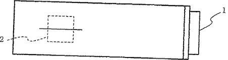
このような従来のカーナビゲーションシステムに取り付けられた内蔵ジャイロセンサーを第1図および第2図に示す。この第1図は内蔵ジャイロセンサーを有するカーナビゲーションシステムを簡略化した図、第2図は第1図のカーナビゲーションシステムを傾斜した状態で装着したときの、内蔵ジャイロセンサーの状態を示す図である。
第1図において、1は例えば、ダッシュボード内に装着されたカーナビゲーションシステム、2はカーナビゲーションシステム1に固定された内蔵ジャイロセンサーである。この内蔵ジャイロセンサー2は車体に対して水平に保持設置することが望ましく、特に水平周り(レート)の角度の絶対値もしくは変化量を検出するジャイロセンサにおいては必要なことであった。
次に動作について説明する。
内蔵ジャイロセンサーユニット装置2はカーナビゲーションシステム1に固定されて装着されているため、内蔵ジャイロセンサー2を車体に対して水平に保持するためには、カーナビゲーションシステム1の車体への搭載的に、カーナビゲーションシステム1自体を水平に設置できる箇所を選ぶ必要があった。
従来の内蔵ジャイロセンサーの取付角度可変機構の取付方法は以上のように構成されているので、カーナビゲーションシステム1を車体に対して水平に装着できない場合、すなわち、内蔵ジャイロセンサー2を車体に対して水平に装着できない場合、内蔵ジャイロセンサー2を傾斜した状態で使用しなければならないため、内蔵ジャイロセンサー2の精度が低下するという課題があった。
この発明は上記のような課題を解決するためになされたもので、カーナビゲーションシステム本体1に内蔵ジャイロセンサー2を取り付ける際、車体搭載時のカーナビゲーションシステム本体1の取付角度に依存することなく、内蔵ジャイロセンサー2の取付角度を水平に調整し、理想的な状態で使用することができる内蔵ジャイロセンサーの取付角度可変機構、および取付角度可変機構の取付方法を得ることを目的とする。
また、水平調節が容易な内蔵ジャイロセンサーの取付角度可変機構、および取付角度可変機構の取付方法を得ることを目的とする。
さらに、手動による水平調整の必要性を省くことができる内蔵ジャイロセンサーの取付角度可変機構、および取付角度可変機構の取付方法を得ることを目的とする。
さらに、車体走行時に生じる加減速Gが内蔵ジャイロセンサーの可動機構に作用することを防止することができる内蔵ジャイロセンサーの取付角度可変機構、および取付角度可変機構の取付方法を得ることを目的とする。
課題を解決するため手段
請求の範囲第1項記載の発明に係る内蔵ジャイロセンサーの取付角度可変機構は、カーナビゲーションシステムに装着され、車体における水平周りの角度の絶対値もしくは変化量を検出する内蔵ジャイロセンサーを車体に対して水平に支持するために、カーナビゲーションシス テム本体の筐体に対し可動自在に支持され、上記カーナ ビゲーションシステム本体の取付角度に応じて、内蔵ジ ャイロセンサーを所定位置または任意位置で固定する内 蔵ジャイロセンサーの取付角度可変機構であって、カー ナビゲーションシステム本体の筐体に形成される取付孔 と、円周部に複数の切込みが形成され、上記取付孔の円 周に沿って回動自在に支持され、内蔵ジャイロセンサー が装着される回転板と、上記カーナビゲーションシステ ム本体の筐体に摺動自在に支持され、上記回転板に形成 される切込みに嵌合し、上記回転板の回動を係止する回 転板ストッパと、この回転板ストッパを上記回転板の方 向に付勢するバネ材とを備えたようにしたものである。
_このことによって、内蔵ジャイロセンサーの精度を低下させない理想的な状態で使用できる、また、切込みの 角度間隔を車種に合わせて形成すれば、市販品として購 入した製品を使用者の車両に容易に装着することができ るなどの効果がある。
請求の範囲第2項記載の範囲に係る内蔵ジャイロセン サーの取付角度可変機構は、カーナビゲーションシステ ムに装着され、車体における水平周りの角度の絶対値も しくは変化量を検出する内蔵ジャイロセンサーを車体に 対して水平に支持するために、カーナビゲーションシス テム本体の筐体に対し可動自在に支持され、上記カーナ ビゲーションシステム本体の取付角度に応じて、内蔵ジ ャイロセンサーを所定位置または任意位置で固定する内 蔵ジャイロセンサーの取付角度可変機構であって、カー ナビゲーションシステム本体の筐体に形成される取付孔 と、この取付孔の円周に沿って回動自在に支持され、内 蔵ジャイロセンサーが装着される回転板と、上記カーナ ビゲーションシステム本体の筐体に摺動自在に支持さ れ、上記回転板の円周部に当接し、上記回転板の回動を 係止する回転板ストッパと、この回転板ストッパを上記 回転板の方向に付勢するバネ材とを備えたようにしたも のである。
このことによって、内蔵ジャイロセンサーの精度を低 下させない理想的な状態で使用できるなどの効果を得る ことができるとともに、微妙な調整を可能にすることが できる効果がある。
発明の実施の形態
以下、この発明をより詳細に説明するために、この発明を実施するための最良の形態について、添付の図面に従って説明する。
参考例1.
第3図はこの発明の参考例1による内蔵ジャイロセンサーの取付角度可変機構を装着したカーナビゲーションシステムを側面から示す図、第4図はこの発明の参考例 1による内蔵ジャイロセンサーの取付角度可変機構を装着したカーナビゲーションシステムを傾斜した状態で装着したときの内蔵ジャイロセンサーの状態を側面から示す図、第5図はこの発明の参考例1による内蔵ジャイロセンサーの取付角度可変機構を装着したカーナビゲーションシステムを傾斜した状態で装着したときの内蔵ジャイロセンサーの状態を正面から示す図である。図において、21はカーナビゲーションシステム、22はカーナビゲーションシステム11に固定された保持凹部23と内蔵ジャイロセンサー31の球形部32から構成される可動機構(取付角度可変機構)、23は内蔵ジャイロセンサー31の球形部32を可動自在に保持する保持凹部、31は上部に腕部を介して球形部32を形成し、レート方位を検出する内蔵ジャイロセンサーである。
次に動作について説明する。
従来のカーナビゲーションシステム1の内蔵ジャイロセンサー2では、第1図および第2図に示す通り、カーナビゲーションシステム1が車体に対して水平ではない状態で設置された場合、内蔵ジャイロセンサー2はカーナビゲーションシステム1に固定されているため、内蔵ジャイロセンサー2の取付角度も車体に対して水平ではなかった。
しかし、この発明の参考例1による内蔵ジャイロセンサー31は、球形部32を介して可動機能22の保持凹部23に可動自在に保持されている。これにより、第4図および第5図に示すように、カーナビゲーションシステム21の本体が車体に対して水平ではない状態で装着された場合でも、内蔵ジャイロセンサー31を車体に対して水平に保持することが可能である。
以上のように、この参考例1によれば、内蔵ジャイロセンサー31の保持角度は、カーナビゲーションシステム21の取付角度に依存することなく、車体に対して水平に保つことができ、内蔵ジャイロセンサー31の精度を一定に保つことができるなどの効果がある。
参考例2.
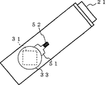
第6図はこの発明の参考例2による内蔵ジャイロセンサーの取付角度可変機構を装着したカーナビゲーションシステムを示す斜視図、第7図はこの発明の参考例2による内蔵ジャイロセンサーの取付角度可変機構を装着したカーナビゲーションシステムを示す側面図、第8図はこの発明の参考例2による内蔵ジャイロセンサーの取付角度可変機構を装着したカーナビゲーションシステムを傾斜した状態で装着したときの内蔵ジャイロセンサーの状態を側面から示す図である。図において、参考例1と同一の符号については同一または相当部分を示すので説明を省略する。24はカーナビゲーションシステム21の側面の筐体部に形成された取付孔(取付角度可変機構)、33はこの取付孔24の円周に沿って回転自在に保持される回転板(取付角度可変機構)であり、この回転板33の内側に内蔵ジャイロセンサー31が装着されている。
次に動作について説明する。
回転板33の内側に内蔵ジャイロセンサー31を装着し、カーナビゲーションシステム21の側面の筐体部に形成された取付孔24に一軸を中心に取付孔24の円周に沿って回転動作が可能なように取り付ける。これにより、第8図に示すように、カーナビゲーションシステム21の本体が車体に対して水平ではない状態で装着された場合でも、回転板33を回転させることにより、内蔵ジャイロセンサー31の取付角度を車体に対して水平に調整することが可能である。この際、この回転板33を何度回転すればよいかをすぐに把握できるように、回転板33の外面に角度目盛りを印刷したり、車種名を直接印刷することにより角度設定の目安とする。
なお、特に車載用のカーナビゲーションシステム21においては、カーナビゲーションシステム21の筐体のロール軸が傾斜すると、正面に設けられている操作盤25が左右にずれるため、ロール軸を傾斜してカーナビゲーションシステム21の筐体を車体に取り付けることは考えられない。したがって、カーナビゲーションシステム21の筐体のピッチ軸の傾斜を調整するのみで適用することができる。
以上のように、この参考例2によれば、比較的簡易な可動機構で内蔵ジャイロセンサー31の水平調整を行うことができる効果がある。
参考例3.
第9図はこの発明の参考例3による内蔵ジャイロセンサーの取付角度可変機構を装着したカーナビゲーションシステムを示す斜視図、第10図はこの発明の参考例3による内蔵ジャイロセンサーの取付角度可変機構を装着したカーナビゲーションシステムを示す側面図、第11図はこの発明の参考例3による内蔵ジャイロセンサーの取付角度可変機構を装着したカーナビゲーションシステムを傾斜した状態で装着したときの内蔵ジャイロセンサーの状態を側面から示す図である。図において、参考例1および参考例2と同一の符号については同一または相当部分を示すので説明を省略する。25は取付孔24の周りに沿って形成された誘導溝(取付角度可変機構)、34は回転板33に形成された締結ピン用孔(取付角度可変機構)、35はこの締結ピン用孔34および誘導溝25を貫通し、この誘導溝25に沿って回転板33を一定角度に誘導する締結ピン(取付角度可変機構)、36は締結ピン35をカーナビゲーションシステム21の側面の筐体部に保持するナットである。
次に動作について説明する。
回転板33の内側に内蔵ジャイロセンサー31を装着し、カーナビゲーションシステム21の側面の筐体部に形成された取付孔24に挿入する。そして、第11図に示すように、カーナビゲーションシステム21の本体が車体に対して水平ではない状態で装着された場合、回転板33をカーナビゲーションシステムの傾斜角度に応じて回転し、内蔵ジャイロセンサー31の水平線軸が車体と水平になるように保持した後、締結ピン35を回転板33の締結ピン用孔34に挿入し、ナット36によりカーナビゲーションシステム21の側面の筐体部に固定する。
以上のように、この参考例3によれば、比較的簡易な可動機構で内蔵ジャイロセンサー31の水平調整を行うことができるとともに、車体の振動による回転板33の水平線軸の位置の狂いを防止することができる効果がある。
実施の形態1.
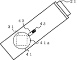
第12図はこの発明の実施の形態1による内蔵ジャイロセンサーの取付角度可変機構を装着したカーナビゲーションシステムを示す図、第13図はこの発明の実施の形態 1による内蔵ジャイロセンサーの取付角度可変機構を装着したカーナビゲーションシステムを右上がり傾斜した状態で装着したときの内蔵ジャイロセンサーの状態を側面から示す図、第14図はこの発明の実施の形態1による内蔵ジャイロセンサーの取付角度可変機構を装着したカーナビゲーションシステムを右下がり傾斜した状態で装着したときの内蔵ジャイロセンサーの状態を側面から示す図である。図において、参考例1から参考例3までと同一の符号については同一または相当部分を示すので説明を省略する。41は複数の切込み41aを形成した回転板(取付角度可変機構)、42はカーナビゲーションシステム21の側面の筐体部に取り付けられ、先端が回転板41の切込み41aに挿入し、回転板41を一定角度に保持する回転板ストッパ(取付角度可変機構)、43は回転板ストッパ42を回転板41側に押圧するバネ材(取付角度可変機構)である。
次に動作について説明する。
回転板41の内側に内蔵ジャイロセンサー31を装着し、カーナビゲーションシステム21の側面の筐体部に形成された取付孔24に挿入する。そして、第13図または第14図に示すように、カーナビゲーションシステム21の本体が車体に対して水平ではない状態で装着された場合、回転板41がカーナビゲーションシステムの傾斜角度に応じて回転し、内蔵ジャイロセンサー31の水平線軸が車体と水平になるように保持した後、回転板ストッパ42の先端を回転板41の切込み41aに挿入し、回転板41を一定角度に保持する。このとき、バネ材43の押圧力により回転板41はカーナビゲーションシステム21の側面の筐体部に固定される。
以上のように、この実施の形態1によれば、比較的簡易な可動機構で内蔵ジャイロセンサー31の水平調整を行うことができるとともに、回転板41の切込み41aの角度間隔を車種に合わせて形成すれば、市販品として購入した製品を使用者の車両に容易に装着することができる効果がある。
実施の形態2.
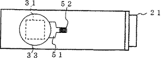
第15図はこの発明の実施の形態2による内蔵ジャイロセンサーの取付角度可変機構を装着したカーナビゲーションシステムを示す図、第16図はこの発明の実施の形態 2による内蔵ジャイロセンサーの取付角度可変機構を装着したカーナビゲーションシステムを右上がり傾斜した状態で装着したときの内蔵ジャイロセンサーの状態を側面から示す図、第17図はこの発明の実施の形態1による内蔵ジャイロセンサーの取付角度可変機構を装着したカーナビゲーションシステムを右下がり傾斜した状態で装着したときの内蔵ジャイロセンサーの状態を側面から示す図である。図において、参考例1から参考例3、及び 実施の形態1までと同一の符号については同一または相当部分を示すので説明を省略する。51は回転板33の円周部と常に当接し、バネ材(取付角度可変機構)52からの圧力により回転板33を所定位置に停止させる抵抗部(取付角度可変機構)であり、回転板33の円周部と抵抗部51との摩擦力により、回転板33を任意の位置に固定させることができる。
次に動作について説明する。
回転板33の内側に内蔵ジャイロセンサー31を装着し、カーナビゲーションシステム21の側面の筐体部に形成された取付孔24に挿入する。そして、第16図または第17図に示すように、カーナビゲーションシステム21の本体が車体に対して水平ではない状態で装着された場合、回転板33をカーナビゲーションシステムの傾斜角度に応じて回転し、内蔵ジャイロセンサー31の水平線軸が車体と水平になるように保持した後、回転板33の円周部と抵抗部51との摩擦力に打ち勝つように回転力を加え回転させ、回転板33を任意の位置に保持する。
以上のように、この実施の形態2によれば、参考例3で使用していた締結ピン用孔34およびナット36による回転板33の解放、及び固定の必要を省略することにより、比較的簡易な可動機構で内蔵ジャイロセンサー31の水平調整を行うことができるとともに、微妙な調整を可能にすることができる効果がある。
参考例4.
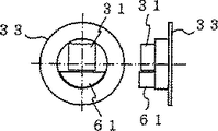
第18図はこの発明の参考例4による内蔵ジャイロセンサーの取付角度可変機構を装着したカーナビゲーションシステムを示す斜視図、第19図はこの発明の参考例4による内蔵ジャイロセンサーの取付角度可変機構の裏面および側面を示す図、第20図はこの発明の参考例4による内蔵ジャイロセンサーの取付角度可変機構を装着したカーナビゲーションシステムを右下がり傾斜した状態で装着したときの内蔵ジャイロセンサーの状態を側面から示す図である。図において、参考例1から参考例3、実施 の形態1、2までと同一の符号については同一または相当部分を示すので説明を省略する。61は取付孔24に回転自在に保持された回転板33の裏面の一端に装着されたバランサー(取付角度可変機構)であり、このバランサー61の重量により回転板33が回転し、内蔵ジャイロセンサー31が車体に対して常に水平状態で保持される。
次に動作について説明する。
回転板33の内側に内蔵ジャイロセンサー31とバランサー61とを装着し、カーナビゲーションシステム21の側面の筐体部に形成された取付孔24に挿入する。この場合、第20図に示すように、カーナビゲーションシステム21の本体が車体に対して水平ではない状態で装着された場合、内蔵ジャイロセンサー31の下面に設けられたバランサー61により、回転板33がカーナビゲーションシステムの傾斜角度に応じて回転し、内蔵ジャイロセンサー31の水平線軸が車体に対して自動的に水平になる。
以上のように、この参考例4によれば、内蔵ジャイロセンサー31の取付角度可変機構の手動による調整を不要にするとともに、内蔵ジャイロセンサー31が常に水平に取り付けられた状態と同程度の精度を保つことができる効果がある。
参考例5.
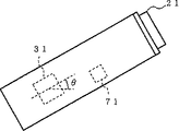
第21図はこの発明の参考例5による内蔵ジャイロセンサーの取付角度可変機構を装着したカーナビゲーションシステムを示す図、第22図はこの発明の参考例5による内蔵ジャイロセンサーの取付角度可変機構を装着したカーナビゲーションシステムを右上がり傾斜した状態で装着したときの内蔵ジャイロセンサーの状態を側面から示す図である。図において、参考例1から参考例4、実施 の形態1、2までと同一の符号については同一または相当部分を示すので説明を省略する。71はカーナビゲーションシステム21の筐体に装着された内蔵ジャイロセンサー31の傾斜θを検出し、カーナビゲーションシステム21の傾斜θに応じて内蔵ジャイロセンサー31からの出力値を補正する傾斜検出機構である。
次に動作について説明する。
第22図に示すように、カーナビゲーションシステム21の本体が車体に対して水平ではない状態で装着された場合、内蔵ジャイロセンサー31の近傍に設けられた傾斜検出機構71がカーナビゲーションシステム21の本体の傾斜θを検出し、カーナビゲーションシステム21の本体の傾斜θに応じて内蔵ジャイロセンサー31からの出力値を、内蔵ジャイロセンサー31が水平に位置したときの値に補正する。
以上のように、この参考例5によれば、カーナビゲーションシステム21の本体が車体に対して水平ではない状態で装着された場合でも、内蔵ジャイロセンサー31からの出力値を内蔵ジャイロセンサー31が水平に位置したときの値に補正することができるため、内蔵ジャイロセンサー31が常に水平に取り付けられた状態と同程度の精度を保つことができる効果がある。
参考例6.
第23図はこの発明の参考例6による内蔵ジャイロセンサーの取付角度可変機構を装着したカーナビゲーションシステムを示す図、図において、参考例1から参考例 5、実施の形態1、2までと同一の符号については同一または相当部分を示すので説明を省略する。81は接触端81aが回転板33に接触し、回転板33の急激な回転力は吸収し、回転板33の緩やかな回転力は吸収しない特性を有する減衰器である。
次に動作について説明する。
カーナビゲーションシステム1が傾斜して車体に取り付けられた場合、バランサー61の重量の重みにより回転板33が比較的低速で回転するため、減衰器81によりその回転力が吸収されることない。したがって、回転板33回転し内蔵ジャイロセンサー31が自動的に水平位置に調整される。一方、車体の走行時には、車体が可加速及び減速を行う度に生じる重力Gがバランサー61に作用し、回転板33を回転させようと作用するが、この時の回転板33の回転力は比較的高速であるため、その回転力は減衰器81によって吸収される。したがって、回転板33はほとんど回転することなく、内蔵ジャイロセンサー31は水平に保持される。
以上のように、この参考例6によれば、内蔵ジャイロセンサー31の取付角度可変機構の手動による調整を不要にし、内蔵ジャイロセンサー31が常に水平に取り付けられた状態と同程度の精度を保つとともに、内蔵ジャイロセンサー31の取付角度可変機構の取付角度が急激に変化することを防止することができる効果がある。
産業上の利用可能性
以上のように、この発明に係る内蔵ジャイロセンサーの取付角度可変機構は、カーナビゲーションシステムにおける内蔵ジャイロセンサーの取付機構として用いるのに適している。
【図面の簡単な説明】
第1図は内蔵ジャイロセンサーを有するカーナビゲーションシステムを簡略化した図である。
第2図は第1図のカーナビゲーションシステムを傾斜した状態で装着したときの、内蔵ジャイロセンサーの状態を示す図である。
第3図はこの発明の参考例1による内蔵ジャイロセンサーの取付角度可変機構を装着したカーナビゲーションシステムを側面から示す図である。
第4図はこの発明の参考例1による内蔵ジャイロセンサーの取付角度可変機構を装着したカーナビゲーションシステムを傾斜した状態で装着したときの内蔵ジャイロセンサーの状態を側面から示す図である。
第5図はこの発明の参考例1による内蔵ジャイロセンサーの取付角度可変機構を装着したカーナビゲーションシステムを傾斜した状態で装着したときの内蔵ジャイロセンサーの状態を正面から示す図である。
第6図はこの発明の参考例2による内蔵ジャイロセンサーの取付角度可変機構を装着したカーナビゲーションシステムを示す斜視図である。
第7図はこの発明の参考例2による内蔵ジャイロセンサーの取付角度可変機構を装着したカーナビゲーションシステムを示す側面図である。
第8図はこの発明の参考例2による内蔵ジャイロセンサーの取付角度可変機構を装着したカーナビゲーションシステムを傾斜した状態で装着したときの内蔵ジャイロセンサーの状態を側面から示す図である。
第9図はこの発明の参考例3による内蔵ジャイロセンサーの取付角度可変機構を装着したカーナビゲーションシステムを示す斜視図である。
第10図はこの発明の参考例3による内蔵ジャイロセンサーの取付角度可変機構を装着したカーナビゲーションシステムを示す側面図である。
第11図はこの発明の参考例3による内蔵ジャイロセンサーの取付角度可変機構を装着したカーナビゲーションシステムを傾斜した状態で装着したときの内蔵ジャイロセンサーの状態を側面から示す図である。
第12図はこの発明の実施の形態1による内蔵ジャイロセンサーの取付角度可変機構を装着したカーナビゲーションシステムを示す図である。
第13図はこの発明の実施の形態1による内蔵ジャイロセンサーの取付角度可変機構を装着したカーナビゲーションシステムを右上がり傾斜した状態で装着したときの内蔵ジャイロセンサーの状態を側面から示す図である。
第14図はこの発明の実施の形態1による内蔵ジャイロセンサーの取付角度可変機構を装着したカーナビゲーションシステムを右下がり傾斜した状態で装着したときの内蔵ジャイロセンサーの状態を側面から示す図である。
第15図はこの発明の実施の形態2による内蔵ジャイロセンサーの取付角度可変機構を装着したカーナビゲーションシステムを示す図である。
第16図はこの発明の実施の形態2による内蔵ジャイロセンサーの取付角度可変機構を装着したカーナビゲーションシステムを右上がり傾斜した状態で装着したときの内蔵ジャイロセンサーの状態を側面から示す図である。
第17図はこの発明の実施の形態1による内蔵ジャイロセンサーの取付角度可変機構を装着したカーナビゲーションシステムを右下がり傾斜した状態で装着したときの内蔵ジャイロセンサーの状態を側面から示す図である。
第18図はこの発明の参考例4による内蔵ジャイロセンサーの取付角度可変機構を装着したカーナビゲーションシステムを示す斜視図である。
第19図はこの発明の参考例4による内蔵ジャイロセンサーの取付角度可変機構の裏面および側面を示す図である。
第20図はこの発明の参考例4による内蔵ジャイロセンサーの取付角度可変機構を装着したカーナビゲーションシステムを右下がり傾斜した状態で装着したときの内蔵ジャイロセンサーの状態を側面から示す図である。
第21図はこの発明の参考例5による内蔵ジャイロセンサーの取付角度可変機構を装着したカーナビゲーションシステムを示す図である。
第22図はこの発明の参考例5による内蔵ジャイロセンサーの取付角度可変機構を装着したカーナビゲーションシステムを右上がり傾斜した状態で装着したときの内蔵ジャイロセンサーの状態を側面から示す図である。
第23図はこの発明の参考例6による内蔵ジャイロセンサーの取付角度可変機構を装着したカーナビゲーションシステムを示す図である。TECHNICAL FIELD OF THE INVENTION
The present invention relates to a built-in gyro sensor unit device capable of leveling a mounting angle of a built-in gyro sensor unit regardless of a mounting angle of a car navigation system to a vehicle body, and a mounting method of a mounting angle variable mechanism.
Conventional technology
As a method of attaching a conventional built-in gyro sensor attachment angle variable mechanism, a method of fixing in a car navigation system has been proposed.
FIG. 1 and FIG. 2 show a built-in gyro sensor attached to such a conventional car navigation system. FIG. 1 is a simplified diagram of a car navigation system having a built-in gyro sensor, and FIG. 2 is a diagram showing a state of the built-in gyro sensor when the car navigation system of FIG. 1 is mounted in an inclined state. .
In FIG. 1,
Next, the operation will be described.
Since the built-in gyro
Since the conventional mounting angle variable mechanism mounting method of the built-in gyro sensor is configured as described above, when the
The present invention has been made to solve the above-described problems. When the built-in
It is another object of the present invention to provide a built-in gyro sensor mounting angle variable mechanism and a mounting angle variable mechanism mounting method that can be easily leveled.
It is another object of the present invention to provide a built-in gyro sensor mounting angle variable mechanism and a mounting angle variable mechanism mounting method that can eliminate the need for manual leveling.
It is another object of the present invention to provide a built-in gyro sensor mounting angle variable mechanism and a mounting angle variable mechanism mounting method capable of preventing acceleration / deceleration G generated during vehicle body travel from acting on the movable mechanism of the built-in gyro sensor. .
Means to solve the problem
The built-in gyro sensor mounting angle variable mechanism according to the first aspect of the present invention is mounted on a car navigation system and includes a built-in gyro sensor for detecting an absolute value or a change amount of a horizontal angle in the vehicle body with respect to the vehicle body. Support horizontallyCar navigation system for The above-mentioned carna Depending on the installation angle of the main body The gyro sensor is fixed in place or at an arbitrary position. This is a variable mounting angle mechanism for the storage gyro sensor. Mounting holes formed in the chassis of the navigation system body And a plurality of cuts are formed in the circumferential portion, and the circle of the mounting hole Built-in gyro sensor supported so as to be rotatable along the circumference And a car navigation system. Is slidably supported by the housing of the main body and formed on the rotating plate A rotation that fits into the cut and locks the rotation of the rotating plate. A rotating plate stopper and this rotating plate stopper And a spring material biased in the direction.
_Thus, it can be used in an ideal state without degrading the accuracy of the built-in gyro sensor.And also of the incision If the angle interval is formed according to the model, it can be purchased as a commercial product. The installed product can be easily mounted on the user's vehicle. There are effects such as.
Built-in gyrocene according to
This reduces the accuracy of the built-in gyro sensor. The effect that it can be used in an ideal state that will not be lowered As well as enabling subtle adjustments. There is an effect that can be done.
BEST MODE FOR CARRYING OUT THE INVENTION
Hereinafter, in order to describe the present invention in more detail, the best mode for carrying out the present invention will be described with reference to the accompanying drawings.
Reference example 1.
FIG. 3 shows the present invention.Reference example 1FIG. 4 is a side view of a car navigation system equipped with a built-in gyro sensor mounting angle variable mechanism according to FIG.Reference example 1FIG. 5 is a side view showing the state of the built-in gyro sensor when the car navigation system equipped with the built-in gyro sensor mounting angle variable mechanism is mounted in an inclined state.Reference example 1It is a figure which shows the state of a built-in gyro sensor when mounting | wearing in the state which inclined the car navigation system which mounted | wore the mounting angle variable mechanism of the built-in gyro sensor by. In the figure, 21 is a car navigation system, 22 is a movable mechanism (mounting angle variable mechanism) composed of a
Next, the operation will be described.
In the built-
But this inventionReference example 1The built-in
As above, thisReference example 1According to the above, the holding angle of the built-in
Reference example 2.
FIG. 6 shows the present invention.Reference example 2FIG. 7 is a perspective view showing a car navigation system equipped with a built-in gyro sensor mounting angle variable mechanism according to FIG.Reference example 2FIG. 8 is a side view showing a car navigation system equipped with a built-in gyro sensor mounting angle variable mechanism according to FIG.Reference example 2It is a figure which shows the state of the built-in gyro sensor when mounting | wearing in the state which inclined the car navigation system which mounted | wore with the mounting angle variable mechanism of the built-in gyro sensor. In the figure,Reference example 1Since the same reference numerals denote the same or corresponding parts, the description thereof will be omitted. 24 is a mounting hole (mounting angle variable mechanism) formed in the casing on the side surface of the
Next, the operation will be described.
The built-
In particular, in the
As above, thisReference example 2According to the above, there is an effect that the horizontal adjustment of the built-in
Reference example 3.
FIG. 9 shows the present invention.Reference example 3FIG. 10 is a perspective view showing a car navigation system equipped with a built-in gyro sensor mounting angle variable mechanism by FIG.Reference example 3FIG. 11 is a side view showing a car navigation system equipped with a built-in gyro sensor mounting angle variable mechanism by FIG.Reference example 3It is a figure which shows the state of the built-in gyro sensor when mounting | wearing in the state which inclined the car navigation system which mounted | wore with the mounting angle variable mechanism of the built-in gyro sensor. In the figure,Reference example 1andReference example 2Since the same reference numerals denote the same or corresponding parts, the description thereof will be omitted.
Next, the operation will be described.
The built-in
As above, thisReference example 3Accordingly, the horizontal adjustment of the built-in
FIG. 12 shows the present invention.Embodiment 1Fig. 13 shows a car navigation system equipped with a variable mounting angle mechanism for the built-in gyro sensor.Embodiment 1Fig. 14 is a side view showing the state of the built-in gyro sensor when the car navigation system equipped with the variable mounting angle mechanism of the built-in gyro sensor is mounted in a state where the built-in gyro sensor is tilted to the right.Embodiment 1It is a figure which shows the state of a built-in gyro sensor from the side, when the car navigation system which mounted | wore the mounting angle variable mechanism of the built-in gyro sensor by mounted | worn in the state which inclined rightward. In the figure,Reference example 1FromReference example 3The same reference numerals as those up to here indicate the same or corresponding parts, and the description thereof will be omitted. 41 is a rotating plate (mounting angle variable mechanism) in which a plurality of cuts 41a are formed, 42 is attached to the casing on the side surface of the
Next, the operation will be described.
The built-in
As above, thisEmbodiment 1According to the above, the horizontal adjustment of the built-in
FIG. 15 shows the present invention.Embodiment 2Fig. 16 shows a car navigation system equipped with a built-in gyro sensor mounting angle variable mechanism according to Fig. 16.Embodiment 2Fig. 17 is a side view showing the state of the built-in gyro sensor when the car navigation system equipped with the built-in gyro sensor mounting angle variable mechanism is mounted in a state where the built-in gyro sensor is tilted to the right.Embodiment 1It is a figure which shows the state of a built-in gyro sensor from the side, when the car navigation system which mounted | wore the mounting angle variable mechanism of the built-in gyro sensor by mounted | worn in the state which inclined rightward. In the figure,Reference Example 1 to Reference Example 3, and Embodiment 1The same reference numerals as those up to here indicate the same or corresponding parts, and the description thereof will be omitted. Reference numeral 51 denotes a resistance portion (mounting angle variable mechanism) that always contacts the circumferential portion of the
Next, the operation will be described.
The built-in
As above, thisEmbodiment 2According toReference example 3By eliminating the need for releasing and fixing the
Reference example 4.
FIG. 18 shows the present invention.Reference example 4FIG. 19 is a perspective view showing a car navigation system equipped with a built-in gyro sensor mounting angle variable mechanism according to FIG.Reference example 4FIG. 20 shows the back and side of the built-in gyro sensor mounting angle variable mechanism by FIG.Reference example 4It is a figure which shows the state of a built-in gyro sensor from the side, when the car navigation system which mounted | wore the mounting angle variable mechanism of the built-in gyro sensor by mounted | worn in the state which inclined rightward. In the figure,Reference example 1 to reference example 3,
Next, the operation will be described.
The built-in
As above, thisReference example 4According to the above, there is an effect that manual adjustment of the mounting angle variable mechanism of the built-in
Reference Example 5.
FIG. 21 shows the present invention.Reference Example 5Fig. 22 shows a car navigation system equipped with a built-in gyro sensor mounting angle variable mechanism according to Fig. 22.Reference Example 5It is a figure which shows the state of a built-in gyro sensor when the car navigation system which mounted | wore the mounting angle variable mechanism of the built-in gyro sensor by mounted | worn in the state which inclined rightward. In the figure,Reference example 1 to reference example 4,
Next, the operation will be described.
As shown in FIG. 22, when the main body of the
As above, thisReference Example 5According to the above, even when the main body of the
Reference Example 6.
FIG. 23 shows the present invention.Reference Example 6In the figure showing a car navigation system equipped with a built-in gyro sensor mounting angle variable mechanism byReference example 1FromReference example 5. Embodiments 1 and 2The same reference numerals as those up to here indicate the same or corresponding parts, and the description thereof will be omitted. Reference numeral 81 denotes an attenuator having a characteristic that the contact end 81a comes into contact with the
Next, the operation will be described.
When the
As above, thisReference Example 6According to the above, it eliminates the need for manual adjustment of the mounting angle variable mechanism of the built-in
Industrial applicability
As described above, the built-in gyro sensor mounting angle variable machine according to the present inventionThe structure isIt is suitable for use as a built-in gyro sensor mounting mechanism in car navigation systems.
[Brief description of the drawings]
FIG. 1 is a simplified diagram of a car navigation system having a built-in gyro sensor.
FIG. 2 is a view showing a state of the built-in gyro sensor when the car navigation system of FIG. 1 is mounted in an inclined state.
FIG. 3 shows the present invention.Reference example 1It is a figure which shows from the side the car navigation system which mounted | wore with the mounting angle variable mechanism of the built-in gyro sensor.
FIG. 4 shows the present invention.Reference example 1It is a figure which shows the state of the built-in gyro sensor when mounting | wearing in the state which inclined the car navigation system which mounted | wore with the mounting angle variable mechanism of the built-in gyro sensor.
FIG. 5 shows the present invention.Reference example 1It is a figure which shows the state of a built-in gyro sensor when mounting | wearing in the state which inclined the car navigation system which mounted | wore the mounting angle variable mechanism of the built-in gyro sensor by.
FIG. 6 shows the present invention.Reference example 2It is a perspective view which shows the car navigation system which mounted | wore the mounting angle variable mechanism of the built-in gyro sensor.
FIG. 7 shows the present invention.Reference example 2It is a side view which shows the car navigation system which mounted | wore the mounting angle variable mechanism of the built-in gyro sensor.
FIG. 8 shows the present invention.Reference example 2It is a figure which shows the state of the built-in gyro sensor when mounting | wearing in the state which inclined the car navigation system which mounted | wore with the mounting angle variable mechanism of the built-in gyro sensor.
FIG. 9 shows the present invention.Reference example 3It is a perspective view which shows the car navigation system which mounted | wore the mounting angle variable mechanism of the built-in gyro sensor.
FIG. 10 shows the present invention.Reference example 3It is a side view which shows the car navigation system which mounted | wore the mounting angle variable mechanism of the built-in gyro sensor.
FIG. 11 shows the present invention.Reference example 3It is a figure which shows the state of the built-in gyro sensor when mounting | wearing in the state which inclined the car navigation system which mounted | wore with the mounting angle variable mechanism of the built-in gyro sensor.
FIG. 12 shows the present invention.Embodiment 1It is a figure which shows the car navigation system which mounted | wore with the mounting angle variable mechanism of the built-in gyro sensor.
FIG. 13 shows the present invention.Embodiment 1It is a figure which shows the state of a built-in gyro sensor when the car navigation system which mounted | wore the mounting angle variable mechanism of the built-in gyro sensor by mounted | worn in the state which inclined rightward.
FIG. 14 shows the present invention.Embodiment 1It is a figure which shows the state of a built-in gyro sensor from the side, when the car navigation system which mounted | wore the mounting angle variable mechanism of the built-in gyro sensor by mounted | worn in the state which inclined rightward.
FIG. 15 shows the present invention.Embodiment 2It is a figure which shows the car navigation system which mounted | wore with the mounting angle variable mechanism of the built-in gyro sensor.
FIG. 16 shows the present invention.Embodiment 2It is a figure which shows the state of a built-in gyro sensor when the car navigation system which mounted | wore the mounting angle variable mechanism of the built-in gyro sensor by mounted | worn in the state which inclined rightward.
FIG. 17 shows the present invention.Embodiment 1It is a figure which shows the state of a built-in gyro sensor from the side, when the car navigation system which mounted | wore the mounting angle variable mechanism of the built-in gyro sensor by mounted | worn in the state which inclined rightward.
FIG. 18 shows the present invention.Reference example 4It is a perspective view which shows the car navigation system which mounted | wore the mounting angle variable mechanism of the built-in gyro sensor.
FIG. 19 shows the present invention.Reference example 4It is a figure which shows the back surface and side surface of the mounting angle variable mechanism of a built-in gyro sensor.
FIG. 20 shows the present invention.Reference example 4It is a figure which shows the state of a built-in gyro sensor from the side, when the car navigation system which mounted | wore the mounting angle variable mechanism of the built-in gyro sensor by mounted | worn in the state which inclined rightward.
FIG. 21 shows the present invention.Reference Example 5It is a figure which shows the car navigation system which mounted | wore with the mounting angle variable mechanism of the built-in gyro sensor.
FIG. 22 shows the present invention.Reference Example 5It is a figure which shows the state of a built-in gyro sensor when the car navigation system which mounted | wore the mounting angle variable mechanism of the built-in gyro sensor by mounted | worn in the state which inclined rightward.
FIG. 23 shows the present invention.Reference Example 6It is a figure which shows the car navigation system which mounted | wore with the mounting angle variable mechanism of the built-in gyro sensor.
Claims (2)
Applications Claiming Priority (1)
| Application Number | Priority Date | Filing Date | Title |
|---|---|---|---|
| PCT/JP1997/002400 WO1999002943A1 (en) | 1997-07-10 | 1997-07-10 | Mechanism for changing attaching angle of built-in gyrosensor and method of mounting mechanism for changing attaching angle |
Publications (1)
| Publication Number | Publication Date |
|---|---|
| JP3621115B2 true JP3621115B2 (en) | 2005-02-16 |
Family
ID=14180829
Family Applications (1)
| Application Number | Title | Priority Date | Filing Date |
|---|---|---|---|
| JP50841899A Expired - Fee Related JP3621115B2 (en) | 1997-07-10 | 1997-07-10 | Built-in gyro sensor mounting angle variable mechanism |
Country Status (4)
| Country | Link |
|---|---|
| US (1) | US6301982B1 (en) |
| EP (1) | EP0995972A4 (en) |
| JP (1) | JP3621115B2 (en) |
| WO (1) | WO1999002943A1 (en) |
Families Citing this family (17)
| Publication number | Priority date | Publication date | Assignee | Title |
|---|---|---|---|---|
| DE19943341A1 (en) * | 1999-09-10 | 2001-03-15 | Nokia Mobile Phones Ltd | Gyro sensor for fitting in vehicles includes a holder for the gyro sensor for determining location and detecting motional components. |
| DE19962823A1 (en) | 1999-12-23 | 2001-06-28 | Mannesmann Vdo Ag | Navigation computer intended for a motor vehicle |
| DE20108649U1 (en) * | 2001-05-23 | 2001-08-30 | Bernstein Ag | Sensor and profile groove housing |
| JP2003227844A (en) | 2002-02-04 | 2003-08-15 | Pioneer Electronic Corp | Sensor device and electronic apparatus for mobile body |
| EP1342620A3 (en) | 2002-02-26 | 2003-12-17 | Lg Electronics Inc. | Front panel operating apparatus and method for an audio device |
| CN100510631C (en) | 2002-05-28 | 2009-07-08 | 多摩川精机株式会社 | Angular velocity sensor |
| JP4108443B2 (en) * | 2002-10-30 | 2008-06-25 | 松下電器産業株式会社 | Positioning device and method for diagnosing installation state of positioning device |
| DE102004041242A1 (en) * | 2004-08-26 | 2006-03-02 | Robert Bosch Gmbh | Method for installing a rotation rate sensor in a navigation unit |
| DE102004060977B3 (en) * | 2004-12-17 | 2006-07-13 | Siemens Ag | Navigation computer with a gyro-sensor |
| CN101365924B (en) | 2006-01-13 | 2012-05-02 | 西铁城控股株式会社 | Vibration body for angular speed sensor |
| JP4871338B2 (en) * | 2008-09-30 | 2012-02-08 | パイオニア株式会社 | Sensor device and mobile electronic device |
| JP4897942B1 (en) * | 2010-09-16 | 2012-03-14 | パイオニア株式会社 | Terminal holding device |
| WO2012035886A1 (en) * | 2010-09-16 | 2012-03-22 | パイオニア株式会社 | Terminal holding device |
| WO2012042606A1 (en) * | 2010-09-29 | 2012-04-05 | パイオニア株式会社 | Terminal holding device |
| JP6569115B2 (en) * | 2016-03-24 | 2019-09-04 | 株式会社三井E&Sマシナリー | Wave power generation apparatus and wave power generation method |
| US11019244B2 (en) * | 2016-05-11 | 2021-05-25 | Ubicquia Iq Llc | Externally viewable orientation indication apparatus and method for an optical sensor |
| CN114867987A (en) | 2020-02-28 | 2022-08-05 | Jvc建伍株式会社 | Navigation device and method for manufacturing navigation device |
Family Cites Families (10)
| Publication number | Priority date | Publication date | Assignee | Title |
|---|---|---|---|---|
| US1282811A (en) * | 1918-05-25 | 1918-10-29 | Louis Goldburg | Damper. |
| US2330955A (en) * | 1940-12-24 | 1943-10-05 | Bliss E W Co | Roll feed auxiliary adjustment |
| US2407696A (en) * | 1945-06-07 | 1946-09-17 | George C Webster | Detent mechanism |
| US3453899A (en) * | 1966-12-23 | 1969-07-08 | Shimano Industrial Co | Exposed speed change mechanism of bicycle |
| JPH08297033A (en) * | 1995-04-27 | 1996-11-12 | Omron Corp | Navigation system |
| JP3296149B2 (en) * | 1995-07-28 | 2002-06-24 | 松下電器産業株式会社 | Angular velocity sensor and navigation device |
| JPH0942979A (en) | 1995-08-03 | 1997-02-14 | Alpine Electron Inc | On-vehicle navigation device |
| KR0153845B1 (en) * | 1995-12-27 | 1998-12-01 | 김광호 | Position controller of gyroscope |
| JP3385851B2 (en) * | 1996-05-31 | 2003-03-10 | アイシン・エィ・ダブリュ株式会社 | Navigation unit |
| US5988654A (en) * | 1997-04-24 | 1999-11-23 | Wix; Michael A. | Automatic leveling system for off-road equipment |
-
1997
- 1997-07-10 JP JP50841899A patent/JP3621115B2/en not_active Expired - Fee Related
- 1997-07-10 WO PCT/JP1997/002400 patent/WO1999002943A1/en active Application Filing
- 1997-07-10 US US09/380,508 patent/US6301982B1/en not_active Expired - Lifetime
- 1997-07-10 EP EP97930755A patent/EP0995972A4/en not_active Withdrawn
Also Published As
| Publication number | Publication date |
|---|---|
| EP0995972A1 (en) | 2000-04-26 |
| US6301982B1 (en) | 2001-10-16 |
| WO1999002943A1 (en) | 1999-01-21 |
| EP0995972A4 (en) | 2003-03-26 |
Similar Documents
| Publication | Publication Date | Title |
|---|---|---|
| JP3621115B2 (en) | Built-in gyro sensor mounting angle variable mechanism | |
| US20050040299A1 (en) | Apparatus and method for universal mounting of a computer system in a vehicle | |
| KR100196807B1 (en) | Inertia sensitive seat belt retractor | |
| JP4897942B1 (en) | Terminal holding device | |
| US4135410A (en) | Inertial locking device | |
| CA2196504C (en) | Acceleration sensor for a vehicle for detecting an acceleration in a predetermined direction | |
| JPH03148350A (en) | Safety belt device with vehicle sensor, of which position is changeable by use of belt winder | |
| JP2003048491A (en) | Angle regulator for on-vehicle camera | |
| JP2001116507A (en) | Angle detecting apparatus | |
| US6435442B1 (en) | Sensor for a belt retractor | |
| KR100501132B1 (en) | Rotation adjusting apparatus of arm rest for automobile | |
| JP2000018938A (en) | On-vehicle type distance measuring apparatus | |
| US5145123A (en) | Seat belt retractor with vehicle sensitive locking mechanism | |
| JP3957111B2 (en) | Acceleration sensor | |
| JPH11326362A (en) | Car-body accelerometer for seat belt | |
| KR19990026743U (en) | Monitor with rear door trim of vehicle | |
| JP3828884B2 (en) | Monitor stand | |
| JPH10175511A (en) | Acceleration sensor device for vehicle | |
| JPH10250530A (en) | Retractor for seat belt | |
| JPH10157569A (en) | Acceleration sensor device for vehicle | |
| JPH02305505A (en) | Arm rest device | |
| JPH1199909A (en) | Vehicle body acceleration sensor for seat belt | |
| JP3740764B2 (en) | Rotation detector mounting structure | |
| JPS6036494Y2 (en) | Back mirror for vehicle | |
| KR100582323B1 (en) | Seat belt retractor |
Legal Events
| Date | Code | Title | Description |
|---|---|---|---|
| A131 | Notification of reasons for refusal |
Free format text: JAPANESE INTERMEDIATE CODE: A131 Effective date: 20040713 |
|
| A521 | Request for written amendment filed |
Free format text: JAPANESE INTERMEDIATE CODE: A523 Effective date: 20040907 |
|
| TRDD | Decision of grant or rejection written | ||
| A01 | Written decision to grant a patent or to grant a registration (utility model) |
Free format text: JAPANESE INTERMEDIATE CODE: A01 Effective date: 20041019 |
|
| A61 | First payment of annual fees (during grant procedure) |
Free format text: JAPANESE INTERMEDIATE CODE: A61 Effective date: 20041117 |
|
| R150 | Certificate of patent or registration of utility model |
Free format text: JAPANESE INTERMEDIATE CODE: R150 |
|
| FPAY | Renewal fee payment (event date is renewal date of database) |
Free format text: PAYMENT UNTIL: 20071126 Year of fee payment: 3 |
|
| FPAY | Renewal fee payment (event date is renewal date of database) |
Free format text: PAYMENT UNTIL: 20081126 Year of fee payment: 4 |
|
| FPAY | Renewal fee payment (event date is renewal date of database) |
Free format text: PAYMENT UNTIL: 20081126 Year of fee payment: 4 |
|
| FPAY | Renewal fee payment (event date is renewal date of database) |
Free format text: PAYMENT UNTIL: 20091126 Year of fee payment: 5 |
|
| FPAY | Renewal fee payment (event date is renewal date of database) |
Free format text: PAYMENT UNTIL: 20091126 Year of fee payment: 5 |
|
| FPAY | Renewal fee payment (event date is renewal date of database) |
Free format text: PAYMENT UNTIL: 20101126 Year of fee payment: 6 |
|
| FPAY | Renewal fee payment (event date is renewal date of database) |
Free format text: PAYMENT UNTIL: 20111126 Year of fee payment: 7 |
|
| FPAY | Renewal fee payment (event date is renewal date of database) |
Free format text: PAYMENT UNTIL: 20121126 Year of fee payment: 8 |
|
| FPAY | Renewal fee payment (event date is renewal date of database) |
Free format text: PAYMENT UNTIL: 20121126 Year of fee payment: 8 |
|
| FPAY | Renewal fee payment (event date is renewal date of database) |
Free format text: PAYMENT UNTIL: 20131126 Year of fee payment: 9 |
|
| LAPS | Cancellation because of no payment of annual fees |