JP3618902B2 - Grid-connected inverter device - Google Patents
Grid-connected inverter device Download PDFInfo
- Publication number
- JP3618902B2 JP3618902B2 JP14569496A JP14569496A JP3618902B2 JP 3618902 B2 JP3618902 B2 JP 3618902B2 JP 14569496 A JP14569496 A JP 14569496A JP 14569496 A JP14569496 A JP 14569496A JP 3618902 B2 JP3618902 B2 JP 3618902B2
- Authority
- JP
- Japan
- Prior art keywords
- temperature
- power
- inverter
- circuit
- fuse
- Prior art date
- Legal status (The legal status is an assumption and is not a legal conclusion. Google has not performed a legal analysis and makes no representation as to the accuracy of the status listed.)
- Expired - Lifetime
Links
Images


Classifications
-
- Y—GENERAL TAGGING OF NEW TECHNOLOGICAL DEVELOPMENTS; GENERAL TAGGING OF CROSS-SECTIONAL TECHNOLOGIES SPANNING OVER SEVERAL SECTIONS OF THE IPC; TECHNICAL SUBJECTS COVERED BY FORMER USPC CROSS-REFERENCE ART COLLECTIONS [XRACs] AND DIGESTS
- Y02—TECHNOLOGIES OR APPLICATIONS FOR MITIGATION OR ADAPTATION AGAINST CLIMATE CHANGE
- Y02E—REDUCTION OF GREENHOUSE GAS [GHG] EMISSIONS, RELATED TO ENERGY GENERATION, TRANSMISSION OR DISTRIBUTION
- Y02E10/00—Energy generation through renewable energy sources
- Y02E10/50—Photovoltaic [PV] energy
- Y02E10/56—Power conversion systems, e.g. maximum power point trackers
Landscapes
- Emergency Protection Circuit Devices (AREA)
- Protection Of Static Devices (AREA)
- Supply And Distribution Of Alternating Current (AREA)
- Inverter Devices (AREA)
Description
【0001】
【発明の属する技術分野】
この発明は、直流電源の直流電力を交流電力に変換し、変換された交流電力を負荷に供給する系統連系インバータ装置の保護に関するものである。
【0002】
【従来の技術】
特開平2−79720号公報に示される太陽光を電源としたインバータ装置では、図12に示すようにインバータの各相の上下アームを構成するスイッチング素子のいずれか一方にヒューズを直列に接続して、スイッチング素子が壊れて短絡した場合、過大な直流短絡電流でヒューズが切れるので、これにより、他の健全なスイッチング素子や制御回路等を保護する方法が提案されている。
【0003】
太陽光を電源とする直流電源は、図13に太陽電池説明図を示すが、電圧−電流特性が一定値Is 以上に上昇することなく、かつ太陽電池を回路内で短絡した場合、すなわち、
太陽電池の出力電圧がゼロとなった場合でも、極端に過大な電流が流れないので、ヒューズが切れず、他の健全なスイッチング素子や制御回路等を保護できないという問題点がある。
このような特性を示す直流電源としては、内部インピーダンスが高い直流電源や電流リミッターを設けている直流電源があるが、このような電源からの出力が短絡等の異常時に検出できず部分的な短絡が長時間続き全体の損傷等につながりかねず、装置の信頼性を著しく損ねるという問題がある。
【0004】
【発明が解決しようとする課題】
本発明は、異常な温度となることを防止し、信頼性の高い装置を得ようというものである。
本発明は、確実な保護の動作を行って安心できるインバータ装置を得ようというものである。
【0005】
【課題を解決するための手段】
交流電力系統と接続され、電圧−電流特性が一定値以上に上昇することなくかつ出力電圧がゼロとなった場合でも極端に過大な電流が流れない直流電源の直流電力を交流電力に変換する電力変換手段と、電力変換手段、制御手段またはこれらを収納するケースの所定箇所の温度が異常となったことを検出する温度検出手段と、検出手段が温度異常を検出した場合に直流電源と電力変換手段とを遮断器により遮断させる制御手段とを有する。
【0017】
【発明の実施の形態】
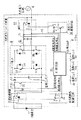
図1は、この発明の実施の形態の一例を示す回路構成図であり、1は太陽電池である直流電源、2は平滑手段のコンデンサ、3A〜3Dはインバータの電力変換を行うスイッチング素子、6は交流電力に変換された電力と連系して図示していない負荷に接続された交流電力系統である。
【0018】
8は各スイッチング素子等を一体にまとめて構成されたスイッチング素子モジュール、9は直流電源と電力変換手段との間に設けられ駆動回路5により直流電力を遮断する直流遮断器、10a〜10cは温度ヒューズ、11は制御回路、12はリアクトルとコンデンサからなり、インバータの交流出力の高周波をカットして波形を改善するフィルター回路、13はインバータ装置と交流電力系統との間に設けられ、系統側異常時にインバータを切り離す等、一方の異常復旧時に他方の影響により感電等しないように連系リレー駆動回路14にて駆動される連系リレーである。
【0019】
15,16,17,18は電流や電圧を検出する検出手段、50は変動する直流電源の電圧を一定に制御する一定電圧制御素子であって、エネルギー蓄積手段51と逆流防止手段52とともに定電圧制御手段を形成している。55は温度ヒューズ10と接続されヒューズの動作を検出し制御回路に伝える検出端子である。
【0020】
このように構成された回路において、太陽電池1は定電圧制御手段を介して系統連系インバータ装置のスイッチング素子3A,3B,3C,3Dに接続され、これらのスイッチング素子等で構成され電力変換を行うインバータ装置は、直流電圧検出手段18及び直流電流検出手段17により入力した電圧、電流より太陽電池1の最適動作点を決定し、その動作点にてPWM制御(パルス幅変調制御)によって、太陽電池1が発電した電力を系統電圧検出手段16及び系統電流検出手段15により系統電圧と同期した正弦波状の電流を交流電力系統6に供給するように制御回路5で制御されるべく構成されている。
【0021】
このような装置において、例えば、スイッチング素子3A,3Dが同時に短絡故障するとスイッチング素子には太陽電池1の短絡電流に略等しい電流が流れる。この短絡電流は従来例で説明した太陽電池の特性により、例えば電流ヒューズの溶断電流より少ないため電流ヒューズにより保護することは困難で短絡が続くとこの電流によりスイッチング素子が高温度になり発熱し損傷等の恐れがあった。
【0022】
このような現象はインバータのスイッチング素子以外にも電解コンデンサ2や、一定電圧制御素子50、各部の接続端子等の電気部品の異常時に発生するし、この回路構成中に示さないトランスやリアクトル等の部品や配線等通電により運転中通常の温度上昇を超えた高温になる箇所が電力変換手段だけでなく制御回路中にもインバータ装置には存在する。
異常時に高温となる箇所にヒューズ10a,10b,10c他を設けることにより異常時の高温を検出することができる。
【0023】
図1の発明の動作を示す回路図において、温度ヒューズ10a,10b,10cが切れていなければ、検出端子55は、グランドに接地されているので、検出端子はLowレベルである。温度ヒューズが切れた場合は、検出端子は、制御回路の制御電源Vcc、すなわちHiレベルとなる。これを検出して、制御回路は、直流遮断器駆動回路のトランジスタを駆動する。これにより、直流遮断器のコイルが動作して、直流遮断器は遮断状態になる。
このように太陽電池は、短絡してもヒューズが切れるような過大な短絡電流が流れないので、回路の保護を行うことができなかったが、インバータ異常時には、インバータ内の温度が上昇するので、これを温度ヒューズにより検出し、直流遮断器を遮断することによりインバータを保護することができ、安全性が向上する。
【0024】
スイッチング素子の保護のために、図2の如くスイッチング素子モジュール8の放熱板23に温度ヒューズを接触させて固定させることにより、確実に異常時の高温と運転時の差が検出でき、この温度差の中間で溶断するヒューズをインバータ装置ケース内に設けるとよい。
【0025】
このヒューズの構造の例を図3に示す。
また、電解コンデンサ2や端子台22等に対してはその近傍で部品よりは上方側にヒューズを近接して設けた例を図2に示す。
【0026】
直流遮断器は通常サービス時には回路の開閉器として用い、保護装置として異常時の遮断にも使用する。
直流遮断器9を駆動動作させる電流が必要であり、直流遮断器駆動回路5にて、制御電源Vcc(例えば12V)にて動作させるとともに、図1において示す如く、直流遮断器9を遮断するためのコイルの電源を交流電力系統6からとる。スイッチング素子が壊れた場合は、直流側からコイルを駆動できるだけの電力がとれるかどうかわからないので、安定している系統から電源をとることにより、直流遮断器を確実に遮断することができて、安全性が向上する。
【0027】
図1、図2において示す如く、温度ヒューズ10をインバータ内に複数個設置し、個々の温度ヒューズを直列接続、片側端をグランドに接地し、もう一方を抵抗を介して制御電源Vccに接続、制御回路は、抵抗と温度ヒューズ間の電圧レベルにより、温度ヒューズの溶断を判定する。
インバータ内の複数箇所の温度上昇を安価な回路で検出でき、インバータ内の複数の箇所の異常温度上昇を検出できるので安全性が向上する。
複数個の温度ヒューズは、スイッチング素子の放熱板とインバータの入力側に設けられた電解コンデンサの近傍、太陽電池とインバータ、交流電力系統とインバータを接続する端子台近傍に設置した例であるが、これにより、スイッチング素子の故障、電解コンデンサの経年劣化故障、端子台の工事不良による異常を直ちに検出でき安全性が向上する。
さらに、スイッチング素子の放熱板に設置する温度ヒューズは溶断温度が120度程度。電解コンデンサの近傍、端子台近傍に設置された温度ヒューズは溶断温度が90度程度のものを使用する。
スイッチング素子の放熱板は、正常時でもある程度の温度上昇がある。一方、電解コンデンサ、端子台は正常であれば、温度上昇がそれほどない。放熱板の温度ヒューズは溶断温度が高いものを使用、電解コンデンサ、端子台は溶断温度が低いものを使用することにより、確実に素早く異常を検出でき、かつ、誤検出を防止できるので、安全性が向上するとともに、信頼性が向上する。
【0028】
なお、ヒューズが放熱板に取り付けられる位置はスイッチング素子の近傍が望ましいが、少々離れていても熱伝導のよい放熱板であれば問題はない。
電解コンデンサは通常、複数設けられており、これらを一括して異常温度が検出できる位置として上部側のコンデンサ近傍に設けている。なお個々のコンデンサの温度異常を検出したければ接触検出させる。端子台は構造上可能であれば接触させてもよい。
【0029】
温度ヒューズ3とヒューズを接続するリード線の接続は、図3の如くカシメにより圧着接続し、かつ、絶縁の為に、耐熱性の透明チューブを被せる。
温度ヒューズをインバータに取り付けられた後でも、ヒューズの溶断を区別できる記号をつけた表示部54を透明チューブの内部に設けるなどにより目視により温度ヒューズの溶断温度を確認でき、複数のヒューズの溶断温度を変えても作業ミスを容易に発見することができ、インバータの信頼性が向上する。さらにこれらのヒューズを後からつけたり取り替えたりする場合でもミスのない作業が可能となる。
【0030】
上記説明では複数のヒューズを直列に設けた例を示したが、ヒューズを並列に設けてもよいことは当然である。但し並列に設けた分だけ検出端子が必要になる。
また、上記は太陽電池の特性から説明したが一定電圧制御素子が故障した場合、例えば、この素子の短絡抵抗は0.1オーム〜10オームレベルという如く故障状況により大巾に変わり短絡電流もこれに応じて流れることになる。このようなケースでは常時温度を計測し、検出された直流電圧と比較して温度が正常か異常かを判断するような直接または間接的に温度を計測する温度検出手段を設けてもよい。
【0031】
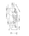
図4,5(図4は立体図、図5は横から見た図)に示す如く、金属部に固定された端子台近傍に温度ヒューズを設置するときは、熱伝導性の悪い取り付け部材で温度ヒューズを金属部に固定する。
これにより、温度ヒューズに加わる熱が金属部に奪われることを防止できるので、端子台の異常による温度上昇を確実に検出でき安全性が向上する。
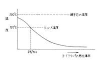
図4、図5の金属板の上に温度ヒューズを設けた例における温度特性図を図6に示す。
コードクリップ34の熱伝導を温度ヒューズ10の温度を示す特性図において、端子台の発熱を温度ヒューズにより検出するためにはコードクリップ34の熱伝導率はおよそ2W/m・K以下である必要がある。コードクリップはフッ素樹脂(四フッ化エチレンポリマー)であり、端子台は熱硬化性樹脂である。
熱伝導率の単位は単位面積、単位長あたりの熱が伝わる割合であり、一般の樹脂の場合は1W/m・K以下程度であ。
【0032】
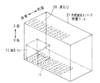
交流電力系統側の異常時やインバータ側の異常時に両者を切り離す連系リレーは、パワーリレーであり、励磁電流が大きい。このリレーが動作を続けると発熱するので動作に余裕を持たせるためインバータ装置のケース内の通風箇所に設けるとよい。図7に示す如く、ケース21の通気口36は上面と下面に設けられ、自然対流を利用して下から上へ空気が流れケース内の発熱を放散している。
特に連系リレーのように発熱が大きくなる可能性のある装置は吸気口である底面の通気口付近に設け、これにより温度上昇を防止してインバータの安全性や信頼性の向上をはかることができる。なおリレー内部を風が下から上へ抜ける構造のものはケース底面に接触させても良いが底面と若干隙間を持たせる方が冷却効果が大きい。
【0033】
図8はスイッチング素子モジュール外形説明図、図9はスイッチング素子モジュール側面図であって、各スイッチング素子とケース内の制御回路との接続をコネクター37を介して行う構成を示す。
なお、ケース内に端子台22を設けているが、これはインバータ装置とケースの外部とを接続する端子であって、コネクター37はスイッチング素子のゲートを制御回路と接続し、スイッチング素子をPWM駆動するゲート信号を伝えている。
図9のモジュール外部に突出するゲート38が回路構成図、図1のスイッチング素子のゲート53である場合は、スイッチング素子基板60の表面に設けたプリント配線でコネクター端子と接続する。
スイッチング素子のゲート端子に、コネクターを取り付けた基板を半田により取り付ける。基板はあらかじめコネクター端子とゲート端子が一対一の関係になるようにプリント配線されている。
このスイッチング素子基板60はゲートに半田により固定しているだけでもよく、また、他の支持手段を追加してモジュールユニット8に設けて支持してもよい。
スイッチング素子は、複数の素子がモジュール化されているので、ゲート端子も複数個あるが、コネクターによりリード線の接続が一括してできるので、作業ミスがなく、かつ、作業性も向上する。
【0034】
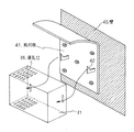
図10,11にインバータ装置を壁に取り付ける構成を示す。インバータ装置のケースは屋内のどこに設けてもよいが、壁に系統連系インバータ装置を取り付ける際に、系統連系インバータのケースに設けられた放熱用の通気口の上部を覆うような逆L字型の取り付け板を壁に設置して、この、逆L字型の取り付け板に系統連系インバータ装置を取り付ける。これにより、インバータ内部に水、埃等の進入を防ぐことができ、かつ、万一インバータ内部が高温になった場合でも、天井のように上部への影響を防ぐことができる。なお、ヒューズ等の温度検出手段の検出温度値は、故障発生が検出できれば装置の信頼性向上につながるため、例えば許容温度以上の温度に設定し、寿命が短くなったとしても検出が確実であれば安全性の高い装置が得られることになる。さらに直列遮断器が遮断されることにより、直流電力の供給が停止されるためインバータ装置が直流電力の不足を検出して連系リレーをオフさせ、これに応じてインバータ装置が連系リレーを動作させて系統から切り離されるので損傷の拡大を防ぐことができる。また上記の説明はヒューズを部品対応で設けることを説明したが、各部の特性から温度を演算する温度検出手段を設け異常を検出してもよいし、あるいはインバータ装置ケースに温度計測素子を設け全体の温度を常時検出し異常温度を検出てもよい。
【0035】
【発明の効果】
この発明は、以上説明したように構成されているので、以下に示すような効果を奏する。
【0036】
電力変換手段または制御手段またはこれらを収納するケースの所定箇所の温度が異常であることを検出して直流遮断器を動作させ直流電流を遮断するので信頼性の高いインバータ装置が得られる。
【0037】
この発明は、遮断器を動作させる電源として交流電力系統からとるので、安全性が一層増すことになる。
【0038】
またこの発明は、温度検出手段を複数箇設置し、少なくとも1個が温度異
常を検出することにより遮断器を動作させるので、安全性を向上させることができる。
【0039】
またこの発明は、ヒューズを直列に接続したので、安価に温度異常を検出できる。
【0040】
またこの発明は、異常時に高温となる箇所に温度検出手段を設けるので、簡単に故障が発見できる。
【0041】
またこの発明は、電気部品の近傍または接触させて温度検出手段を設けるので、確実に故障が発見できる。
【0042】
またこの発明は、複数の温度検出手段の異常を検出する温度を各々個々に設けたので、装置内システム全体の安全性が一層高められる。
【0043】
またこの発明は、スイッチング素子と他の部品との温度検出値を変えたので、誤動作を防止でき信頼性の高い装置が得られる。
【0044】
またこの発明は、異常を検出する温度を検出手段に表示したので、製造途中等のミスを防止でき信頼性が高い装置が得られる。
【0045】
またこの発明は、熱伝導しにくい部材で温度検出手段を固定するので、温度上昇を確実に検出でき、検出不良を防止できる。
【0046】
またこの発明は、発熱の大きくなる連系リレーを放熱のよい位置に配置したので、安全性の高い装置が得られる。
【0047】
またこの発明は、モジュール手段の表面にコネクターを設け接続する構成にしたので、作業性の高い、信頼性のある装置が得られる。
【図面の簡単な説明】
【図1】本発明の実施の形態の一例を示す回路構成図である。
【図2】本発明の実施の形態の一例を示すインバータ装置内部構造説明図である。
【図3】温度ヒューズ構造図である。
【図4】端子台構造斜視図である。
【図5】端子台構造側面説明図である。
【図6】温度特性図である。
【図7】ケース構造図である。
【図8】スイッチング素子モジュール外形説明図である。
【図9】スイッチング素子モジュール側面図である。
【図10】インバータ装置取付説明図である。
【図11】インバータ装置取付側面図である。
【図12】従来の回路構成図である。
【図13】太陽電池特性図である。
【符号の説明】
1 太陽電池、2 電解コンデンサ、3A〜3D スイッチング素子、4A,4B ヒューズ、5 直流遮断器駆動回路、6 交流電力系統、7 負荷、8 スイッチング素子モジュール、9 直流遮断器、10,10a,10b,10c ヒューズ、11 制御回路、12 フィルター、13 連系リレー、14 連系リレー駆動回路、15 電流検出手段、16 電圧検出手段、17 電流検出手段、18 電圧検出手段、21 系統連系インバータ装置ケース、22 端子台、23 放熱板、24 基板、31 リード線、32 カシメ接続部、33 耐熱透明絶縁チューブ、34 コードクリップ、35 金属板、36 通気口、37 コネクター、38 ゲート、39 半田付、40 壁、41 取付板、42 系合手段、50 一定電圧制御素子、51 エネルギー蓄積手段、52 逆流防止手段、53 ゲート、54 表示部、55 検出端子、60 スイッチング素子基板。[0001]
BACKGROUND OF THE INVENTION
The present invention relates to protection of a grid-connected inverter device that converts DC power of a DC power source into AC power and supplies the converted AC power to a load.
[0002]
[Prior art]
In an inverter device using solar power as disclosed in Japanese Patent Laid-Open No. 2-79720, as shown in FIG. 12, a fuse is connected in series to one of the switching elements constituting the upper and lower arms of each phase of the inverter. When the switching element is broken and short-circuited, the fuse is blown by an excessive DC short-circuit current, and thus a method for protecting other healthy switching elements, control circuits, and the like has been proposed.
[0003]
The direct current power source using solar power as shown in FIG. 13 is an explanatory diagram of the solar cell. When the voltage-current characteristic does not rise above a certain value Is and the solar cell is short-circuited in the circuit,
Even when the output voltage of the solar cell becomes zero, an extremely excessive current does not flow, so that there is a problem that the fuse is not blown and other healthy switching elements and control circuits cannot be protected.
DC power supplies exhibiting such characteristics include DC power supplies with high internal impedance and DC power supplies with a current limiter, but the output from such power supplies cannot be detected in the event of an abnormality such as a short circuit, resulting in a partial short circuit. However, there is a problem that the reliability of the apparatus is remarkably deteriorated because it may last for a long time and lead to damage of the entire apparatus.
[0004]
[Problems to be solved by the invention]
The present invention is intended to prevent a temperature from becoming abnormal and to obtain a highly reliable device.
An object of the present invention is to obtain an inverter device that can be relieved by performing a reliable protection operation.
[0005]
[Means for Solving the Problems]
Power that is connected to an AC power system and that converts DC power from a DC power source into AC power that does not cause an excessively large current even when the voltage-current characteristics do not rise above a certain value and the output voltage becomes zero. Conversion means, power conversion means , control means, or temperature detection means for detecting that the temperature at a predetermined location of the case housing them is abnormal, and when the detection means detects a temperature abnormality, a DC power source and power conversion And a control means for interrupting the means with a circuit breaker .
[0017]
DETAILED DESCRIPTION OF THE INVENTION
FIG. 1 is a circuit configuration diagram showing an example of an embodiment of the present invention, where 1 is a DC power source that is a solar cell, 2 is a capacitor of a smoothing means, 3A to 3D are switching elements that perform power conversion of an inverter, 6 Is an AC power system connected to a load (not shown) linked to the power converted to AC power.
[0018]
8 is a switching element module configured by integrating each switching element and the like, 9 is a DC circuit breaker provided between the DC power supply and the power conversion means, and blocking DC power by the drive circuit 5, and 10a to 10c are temperature Fuse, 11 is a control circuit, 12 is a filter circuit that consists of a reactor and a capacitor and cuts the high frequency of the AC output of the inverter to improve the waveform, and 13 is provided between the inverter device and the AC power system. The relay is driven by the relay relay driving circuit 14 so as not to cause an electric shock or the like due to the influence of the other when an abnormality is restored, such as sometimes disconnecting the inverter.
[0019]
[0020]
In the circuit configured as described above, the
[0021]
In such a device, for example, when the switching elements 3A and 3D are short-circuited simultaneously, a current substantially equal to the short-circuit current of the
[0022]
Such a phenomenon occurs when there is an abnormality in the
By providing the fuses 10a, 10b, 10c and the like at locations where the temperature becomes high at the time of abnormality, the high temperature at the time of abnormality can be detected.
[0023]
In the circuit diagram showing the operation of the invention of FIG. 1, if the thermal fuses 10a, 10b, and 10c are not blown, the detection terminal 55 is grounded, so the detection terminal is at the low level. When the thermal fuse is blown, the detection terminal becomes the control power supply Vcc of the control circuit, that is, the Hi level. Upon detecting this, the control circuit drives the transistor of the DC circuit breaker drive circuit. As a result, the coil of the DC circuit breaker operates, and the DC circuit breaker enters a cut-off state.
In this way, the solar cell could not protect the circuit because there was no excessive short-circuit current that would blow the fuse even if short-circuited, but when the inverter is abnormal, the temperature inside the inverter rises, This can be detected by a thermal fuse, and the inverter can be protected by breaking the DC breaker, improving safety.
[0024]
In order to protect the switching element, a temperature fuse is brought into contact with and fixed to the heat radiating plate 23 of the
[0025]
An example of the structure of this fuse is shown in FIG.
Further, FIG. 2 shows an example in which a fuse is provided close to the
[0026]
The DC circuit breaker is used as a circuit switch during normal service, and it is also used as a protective device to shut down when there is an abnormality.
A current for driving the DC circuit breaker 9 is required, and the DC circuit breaker drive circuit 5 is operated with a control power supply Vcc (for example, 12 V), and as shown in FIG. The coil power source is taken from the AC power system 6. If the switching element breaks, it is not known whether or not enough power can be taken to drive the coil from the DC side. By taking power from a stable system, the DC circuit breaker can be shut off reliably and safety Improves.
[0027]
As shown in FIGS. 1 and 2, a plurality of temperature fuses 10 are installed in the inverter, each temperature fuse is connected in series, one end is grounded, and the other is connected to the control power supply Vcc via a resistor. The control circuit determines whether the thermal fuse is blown based on the voltage level between the resistor and the thermal fuse.
Temperature increases at a plurality of locations in the inverter can be detected by an inexpensive circuit, and abnormal temperature increases at a plurality of locations in the inverter can be detected, thus improving safety.
A plurality of thermal fuses is an example installed near the terminal plate connecting the heat sink of the switching element and the electrolytic capacitor provided on the input side of the inverter, the solar cell and the inverter, the AC power system and the inverter, As a result, failure due to switching element failure, aging deterioration failure of the electrolytic capacitor, and malfunction due to poor construction of the terminal block can be immediately detected, and safety is improved.
Furthermore, the thermal fuse installed on the heat sink of the switching element has a fusing temperature of about 120 degrees. Use a thermal fuse with a fusing temperature of about 90 degrees near the electrolytic capacitor and terminal block.
The heat dissipation plate of the switching element has a certain temperature rise even under normal conditions. On the other hand, if the electrolytic capacitor and the terminal block are normal, the temperature does not increase so much. The use of a heat sink with a high fusing temperature and the use of an electrolytic capacitor and terminal block with a low fusing temperature ensure that abnormalities can be detected quickly and reliably, thus preventing safety. And the reliability is improved.
[0028]
It should be noted that the position where the fuse is attached to the heat radiating plate is preferably in the vicinity of the switching element, but there is no problem as long as the heat radiating plate has good heat conduction even if it is a little away.
Usually, a plurality of electrolytic capacitors are provided, and these are provided in the vicinity of the upper capacitor as a position where abnormal temperatures can be detected collectively. If it is desired to detect an abnormal temperature of each capacitor, contact detection is performed. The terminal block may be brought into contact if structurally possible.
[0029]
As shown in FIG. 3, the thermal fuse 3 and the lead wire for connecting the fuse are crimped by caulking and covered with a heat-resistant transparent tube for insulation.
Even after the thermal fuse is attached to the inverter, the fusing temperature of the thermal fuse can be confirmed visually by providing a
[0030]
In the above description, an example in which a plurality of fuses are provided in series has been described, but it is a matter of course that fuses may be provided in parallel. However, as many detection terminals as are provided in parallel are required.
Although the above has been described from the characteristics of the solar cell, when a constant voltage control element fails, for example, the short-circuit resistance of this element varies greatly depending on the failure condition, such as 0.1 ohm to 10 ohm level, and the short-circuit current also changes. Depending on the flow. In such a case, a temperature detecting means for measuring the temperature constantly and measuring the temperature directly or indirectly so as to determine whether the temperature is normal or abnormal compared with the detected DC voltage may be provided.
[0031]
As shown in FIGS. 4 and 5 (FIG. 4 is a three-dimensional view and FIG. 5 is a side view), when installing a thermal fuse in the vicinity of a terminal block fixed to a metal part, use a mounting member with poor thermal conductivity. Fix the thermal fuse to the metal part.
As a result, it is possible to prevent the heat applied to the thermal fuse from being taken away by the metal part, so that an increase in temperature due to an abnormality of the terminal block can be reliably detected, and safety is improved.
FIG. 6 shows a temperature characteristic diagram in an example in which a thermal fuse is provided on the metal plate of FIGS.
In the characteristic diagram showing the thermal conduction of the cord clip 34 indicating the temperature of the thermal fuse 10, the thermal conductivity of the cord clip 34 needs to be about 2 W / m · K or less in order to detect the heat generation of the terminal block by the thermal fuse. is there. The cord clip is a fluororesin (tetrafluoroethylene polymer), and the terminal block is a thermosetting resin.
The unit of thermal conductivity is the rate at which heat per unit area and unit length is transmitted. In the case of a general resin, it is about 1 W / m · K or less.
[0032]
The interconnection relay that disconnects both in the case of an abnormality on the AC power system side or on the inverter side is a power relay and has a large excitation current. Since this relay generates heat when it continues to operate, it is preferable to provide it at a ventilated place in the case of the inverter device in order to allow a sufficient operation. As shown in FIG. 7, the
In particular, devices that generate large amounts of heat, such as interconnected relays, are installed near the bottom vent, which is the inlet, which prevents temperature rise and improves inverter safety and reliability. it can. In addition, the structure in which the wind passes through the relay from the bottom to the top may be brought into contact with the bottom surface of the case, but the cooling effect is greater when a slight gap is provided between the bottom surface and the case.
[0033]
FIG. 8 is an explanatory diagram of the external appearance of the switching element module, and FIG. 9 is a side view of the switching element module, showing a configuration in which each switching element and the control circuit in the case are connected via a connector 37.
The terminal block 22 is provided in the case. This is a terminal for connecting the inverter device and the outside of the case. The connector 37 connects the gate of the switching element to the control circuit, and the switching element is PWM driven. The gate signal is transmitted.
When the
A board with a connector is attached to the gate terminal of the switching element by soldering. The board is printed in advance so that the connector terminals and the gate terminals have a one-to-one relationship.
The switching element substrate 60 may be simply fixed to the gate by soldering, or may be supported by being provided in the
Since a plurality of switching elements are modularized, there are a plurality of gate terminals. However, since lead wires can be connected together by a connector, there is no work mistake and workability is improved.
[0034]
10 and 11 show a configuration in which the inverter device is attached to the wall. The inverter device case can be installed anywhere indoors, but when installing the grid-connected inverter device on the wall, it is an inverted L shape that covers the top of the heat dissipation vent provided in the case of the grid-connected inverter A mold attachment plate is installed on the wall, and the grid-connected inverter device is attached to the inverted L-shaped attachment plate. Thereby, water, dust, etc. can be prevented from entering the inverter, and even if the inverter becomes hot, it is possible to prevent the upper part from being affected like the ceiling. Note that the detection temperature value of the temperature detection means such as a fuse will improve the reliability of the device if the occurrence of a failure can be detected.For example, even if the temperature is set to a temperature higher than the allowable temperature and the life is shortened, the detection can be ensured. In this case, a highly safe device can be obtained. By further blocked series breaker, the inverter device for supplying the DC power is stopped to detect the shortage of the DC power is turned off the interconnection relay, operating the connector relay inverter apparatus according to this Since it is separated from the system, damage can be prevented from spreading. In the above description, the fuse is provided for each part. However, the temperature detection means for calculating the temperature from the characteristics of each part may be provided to detect the abnormality, or the inverter device case may be provided with a temperature measuring element as a whole. Alternatively, the abnormal temperature may be detected by constantly detecting the temperature.
[0035]
【The invention's effect】
Since the present invention is configured as described above, the following effects can be obtained.
[0036]
Since it is detected that the temperature of the power conversion means, the control means, or a predetermined location of the case housing them is abnormal and the DC breaker is operated to cut off the DC current, a highly reliable inverter device can be obtained.
[0037]
Since this invention is taken from an AC power system as a power source for operating the circuit breaker, safety is further increased.
[0038]
Moreover, since this invention installs several temperature detection means and at least 1 detects a temperature abnormality and operates a circuit breaker, it can improve safety | security.
[0039]
Further, according to the present invention, since the fuses are connected in series, the temperature abnormality can be detected at a low cost.
[0040]
Further, according to the present invention, since the temperature detecting means is provided at a location where the temperature becomes high at the time of abnormality, a failure can be easily found.
[0041]
Further, according to the present invention, since the temperature detecting means is provided in the vicinity of or in contact with the electric component, a failure can be reliably detected.
[0042]
Further, according to the present invention, since the temperatures for detecting the abnormality of the plurality of temperature detecting means are individually provided, the safety of the entire system in the apparatus is further enhanced.
[0043]
Further, according to the present invention, since the temperature detection values of the switching element and other components are changed, a malfunction can be prevented and a highly reliable device can be obtained.
[0044]
Further, according to the present invention, the temperature at which the abnormality is detected is displayed on the detection means, so that a mistake in the manufacturing process or the like can be prevented and a highly reliable apparatus can be obtained.
[0045]
Further, according to the present invention, since the temperature detecting means is fixed by a member that is difficult to conduct heat, a temperature rise can be detected reliably and a detection failure can be prevented.
[0046]
Further, according to the present invention, since the interconnection relay that generates a large amount of heat is disposed at a position where heat dissipation is good, a highly safe device can be obtained.
[0047]
Further, according to the present invention, since the connector is provided on the surface of the module means and connected, a highly workable and reliable device can be obtained.
[Brief description of the drawings]
FIG. 1 is a circuit configuration diagram showing an example of an embodiment of the present invention.
FIG. 2 is an explanatory diagram of an internal structure of an inverter device showing an example of an embodiment of the present invention.
FIG. 3 is a structural diagram of a thermal fuse.
FIG. 4 is a perspective view of a terminal block structure.
FIG. 5 is a side view of a terminal block structure.
FIG. 6 is a temperature characteristic diagram.
FIG. 7 is a case structure diagram.
FIG. 8 is an explanatory diagram of a switching element module outer shape.
FIG. 9 is a side view of a switching element module.
FIG. 10 is an explanatory diagram of inverter device attachment.
FIG. 11 is a side view of the inverter device mounting.
FIG. 12 is a conventional circuit configuration diagram.
FIG. 13 is a characteristic diagram of a solar cell.
[Explanation of symbols]
DESCRIPTION OF
Claims (1)
前記電力変換手段、前記制御手段またはこれらを収納するケースの所定箇所の温度が異常となったことを検出する温度検出手段と、
前記検出手段が温度異常を検出した場合に前記直流電源と前記電力変換手段とを遮断器により遮断させる制御手段とを有する系統連系インバータ装置。Power that is connected to an AC power system and that converts DC power from a DC power source into AC power that does not cause an excessively large current even when the voltage-current characteristics do not rise above a certain value and the output voltage becomes zero. Conversion means;
Temperature detecting means for detecting that the pre-Symbol power converting means, the temperature of the predetermined portion of the case for housing the control unit or these is abnormal,
A grid-connected inverter device comprising: a control unit that shuts off the DC power source and the power conversion unit by a circuit breaker when the detection unit detects a temperature abnormality .
Priority Applications (1)
| Application Number | Priority Date | Filing Date | Title |
|---|---|---|---|
| JP14569496A JP3618902B2 (en) | 1996-06-07 | 1996-06-07 | Grid-connected inverter device |
Applications Claiming Priority (1)
| Application Number | Priority Date | Filing Date | Title |
|---|---|---|---|
| JP14569496A JP3618902B2 (en) | 1996-06-07 | 1996-06-07 | Grid-connected inverter device |
Publications (2)
| Publication Number | Publication Date |
|---|---|
| JPH09327178A JPH09327178A (en) | 1997-12-16 |
| JP3618902B2 true JP3618902B2 (en) | 2005-02-09 |
Family
ID=15390949
Family Applications (1)
| Application Number | Title | Priority Date | Filing Date |
|---|---|---|---|
| JP14569496A Expired - Lifetime JP3618902B2 (en) | 1996-06-07 | 1996-06-07 | Grid-connected inverter device |
Country Status (1)
| Country | Link |
|---|---|
| JP (1) | JP3618902B2 (en) |
Families Citing this family (25)
| Publication number | Priority date | Publication date | Assignee | Title |
|---|---|---|---|---|
| JPH11289752A (en) * | 1998-03-31 | 1999-10-19 | Fuji Electric Co Ltd | Device for advance noticing of capacitor end of life to power conversion device |
| JP2000152655A (en) * | 1998-11-09 | 2000-05-30 | Nissin Electric Co Ltd | Power converter |
| JP2001028883A (en) * | 1999-07-12 | 2001-01-30 | Sanyo Electric Co Ltd | Power device |
| JP2001028884A (en) * | 1999-07-12 | 2001-01-30 | Sanyo Electric Co Ltd | Power device |
| JP2001238465A (en) * | 2000-02-25 | 2001-08-31 | Sharp Corp | Inverter device |
| JP2002191190A (en) * | 2000-12-21 | 2002-07-05 | Nippon Densan Corp | Motor control device |
| JP4693256B2 (en) * | 2001-02-02 | 2011-06-01 | シャープ株式会社 | Booster unit |
| JP3651406B2 (en) * | 2001-03-29 | 2005-05-25 | 株式会社日立製作所 | Power converter |
| JP2003204677A (en) * | 2002-01-08 | 2003-07-18 | Toshiba Corp | Power converter |
| JP2003333863A (en) * | 2002-05-15 | 2003-11-21 | Sanyo Electric Co Ltd | Power supply |
| JP3806381B2 (en) * | 2002-08-30 | 2006-08-09 | 三菱重工業株式会社 | Motor control module |
| JP4433817B2 (en) * | 2004-02-10 | 2010-03-17 | パナソニック電工株式会社 | Power converter |
| JP2006042406A (en) * | 2004-07-22 | 2006-02-09 | Fuji Electric Fa Components & Systems Co Ltd | Stack structure of power converter |
| JP4452605B2 (en) * | 2004-11-10 | 2010-04-21 | トヨタ自動車株式会社 | Semiconductor device |
| JP4583283B2 (en) * | 2005-10-05 | 2010-11-17 | 東芝燃料電池システム株式会社 | Inverter for grid connection, control method thereof and interconnected operation system |
| JP2009278774A (en) * | 2008-05-14 | 2009-11-26 | Nissin Electric Co Ltd | Photovoltaic power generating system |
| KR200445517Y1 (en) * | 2009-04-27 | 2009-08-06 | 윤희복 | Module for connection board of photovoltaic power generation device |
| JP2012110109A (en) * | 2010-11-16 | 2012-06-07 | Omron Corp | Output stage film capacitor structure of power conditioner |
| EP2781624A1 (en) * | 2013-03-19 | 2014-09-24 | Siemens Aktiengesellschaft | Electrolysis stack and electrolysing device |
| JP6476912B2 (en) * | 2015-01-26 | 2019-03-06 | 株式会社ノーリツ | Inverter |
| CN115979461A (en) * | 2016-03-23 | 2023-04-18 | 太阳能安吉科技有限公司 | Conductor temperature detector |
| US10658833B2 (en) | 2016-03-23 | 2020-05-19 | Solaredge Technologies Ltd. | Conductor temperature detector |
| JP6677056B2 (en) * | 2016-04-11 | 2020-04-08 | 住友電気工業株式会社 | Power converter |
| JP6665683B2 (en) * | 2016-05-23 | 2020-03-13 | 住友電気工業株式会社 | Power conversion device and solar power generation system |
| JP6277433B2 (en) * | 2016-07-28 | 2018-02-14 | パナソニックIpマネジメント株式会社 | Power converter |
-
1996
- 1996-06-07 JP JP14569496A patent/JP3618902B2/en not_active Expired - Lifetime
Also Published As
| Publication number | Publication date |
|---|---|
| JPH09327178A (en) | 1997-12-16 |
Similar Documents
| Publication | Publication Date | Title |
|---|---|---|
| JP3618902B2 (en) | Grid-connected inverter device | |
| KR101470348B1 (en) | Photovoltaic power generation system having fire prevention apparatus | |
| JP5555249B2 (en) | Electrical circuit connected with thermal switch with three terminals and its connection method | |
| JP6042883B2 (en) | Inverter with moisture status monitoring and method for operating the inverter | |
| US10270317B2 (en) | Motor temperature monitoring | |
| JP2009540550A (en) | Connection box for overheating protection of individual solar panels | |
| JP6094772B2 (en) | Power conversion device, method for manufacturing power conversion device, and electric equipment | |
| US7031132B1 (en) | Short circuit diagnostic tool | |
| US6297573B1 (en) | Three-phase motor | |
| US11486600B2 (en) | Air conditioner | |
| WO2019123545A1 (en) | Air conditioner | |
| KR101684679B1 (en) | Solar Power Plant With Fire-Protection Function By Detecting The State Of Node Bolt's Tension In The Junction Box | |
| KR101550039B1 (en) | Photovoltaic power generation system having fire prevention apparatus | |
| KR101652710B1 (en) | System for monitoring power of junction box | |
| JP2009117535A (en) | Solid-state relay and electronic equipment mounted with the same | |
| KR102138232B1 (en) | Photovoltaic power generation system to prevent fire of connection box in advance | |
| JP6278815B2 (en) | Terminal block and power equipment | |
| JP2005341681A (en) | Lightning arrester | |
| JP2005268258A (en) | Power converter | |
| EP4362256A1 (en) | Aircraft solid state power controller and method of monitoring the temperature of a solid state switch in an aircraft solid state power controller | |
| JP2621075B2 (en) | Protection circuit | |
| KR20070044094A (en) | Power terminal block for preventing overheating | |
| JPH0537137Y2 (en) | ||
| KR200251196Y1 (en) | Overheating check apparatus of leakage of electricity breaker | |
| KR100993553B1 (en) | A battery terminal damage preventing structure in vehicle |
Legal Events
| Date | Code | Title | Description |
|---|---|---|---|
| A521 | Written amendment |
Free format text: JAPANESE INTERMEDIATE CODE: A523 Effective date: 20040705 |
|
| RD01 | Notification of change of attorney |
Free format text: JAPANESE INTERMEDIATE CODE: A7421 Effective date: 20040715 |
|
| A61 | First payment of annual fees (during grant procedure) |
Free format text: JAPANESE INTERMEDIATE CODE: A61 Effective date: 20041111 |
|
| FPAY | Renewal fee payment (event date is renewal date of database) |
Free format text: PAYMENT UNTIL: 20071119 Year of fee payment: 3 |
|
| FPAY | Renewal fee payment (event date is renewal date of database) |
Free format text: PAYMENT UNTIL: 20081119 Year of fee payment: 4 |
|
| FPAY | Renewal fee payment (event date is renewal date of database) |
Free format text: PAYMENT UNTIL: 20081119 Year of fee payment: 4 |
|
| FPAY | Renewal fee payment (event date is renewal date of database) |
Free format text: PAYMENT UNTIL: 20091119 Year of fee payment: 5 |
|
| FPAY | Renewal fee payment (event date is renewal date of database) |
Free format text: PAYMENT UNTIL: 20091119 Year of fee payment: 5 |
|
| FPAY | Renewal fee payment (event date is renewal date of database) |
Free format text: PAYMENT UNTIL: 20101119 Year of fee payment: 6 |
|
| FPAY | Renewal fee payment (event date is renewal date of database) |
Free format text: PAYMENT UNTIL: 20111119 Year of fee payment: 7 |
|
| FPAY | Renewal fee payment (event date is renewal date of database) |
Free format text: PAYMENT UNTIL: 20121119 Year of fee payment: 8 |
|
| FPAY | Renewal fee payment (event date is renewal date of database) |
Free format text: PAYMENT UNTIL: 20121119 Year of fee payment: 8 |
|
| FPAY | Renewal fee payment (event date is renewal date of database) |
Free format text: PAYMENT UNTIL: 20131119 Year of fee payment: 9 |
|
| R250 | Receipt of annual fees |
Free format text: JAPANESE INTERMEDIATE CODE: R250 |
|
| EXPY | Cancellation because of completion of term |