JP3616640B2 - Support legs - Google Patents
Support legs Download PDFInfo
- Publication number
- JP3616640B2 JP3616640B2 JP50429894A JP50429894A JP3616640B2 JP 3616640 B2 JP3616640 B2 JP 3616640B2 JP 50429894 A JP50429894 A JP 50429894A JP 50429894 A JP50429894 A JP 50429894A JP 3616640 B2 JP3616640 B2 JP 3616640B2
- Authority
- JP
- Japan
- Prior art keywords
- platform
- support
- upright
- fixing
- elongated
- Prior art date
- Legal status (The legal status is an assumption and is not a legal conclusion. Google has not performed a legal analysis and makes no representation as to the accuracy of the status listed.)
- Expired - Fee Related
Links
- 230000000087 stabilizing effect Effects 0.000 claims description 14
- 230000000712 assembly Effects 0.000 claims description 2
- 238000000429 assembly Methods 0.000 claims description 2
- 239000007787 solid Substances 0.000 claims 1
- 239000000463 material Substances 0.000 description 8
- 239000011120 plywood Substances 0.000 description 4
- 239000000853 adhesive Substances 0.000 description 2
- 230000001070 adhesive effect Effects 0.000 description 2
- 238000003466 welding Methods 0.000 description 2
- 230000008878 coupling Effects 0.000 description 1
- 238000010168 coupling process Methods 0.000 description 1
- 238000005859 coupling reaction Methods 0.000 description 1
- 238000010586 diagram Methods 0.000 description 1
- 239000003292 glue Substances 0.000 description 1
- 239000002184 metal Substances 0.000 description 1
- 230000004048 modification Effects 0.000 description 1
- 238000012986 modification Methods 0.000 description 1
- 230000006641 stabilisation Effects 0.000 description 1
- 238000011105 stabilization Methods 0.000 description 1
- 239000002023 wood Substances 0.000 description 1
Images


Classifications
-
- E—FIXED CONSTRUCTIONS
- E04—BUILDING
- E04G—SCAFFOLDING; FORMS; SHUTTERING; BUILDING IMPLEMENTS OR AIDS, OR THEIR USE; HANDLING BUILDING MATERIALS ON THE SITE; REPAIRING, BREAKING-UP OR OTHER WORK ON EXISTING BUILDINGS
- E04G1/00—Scaffolds primarily resting on the ground
- E04G1/28—Scaffolds primarily resting on the ground designed to provide support only at a low height
- E04G1/32—Other free-standing supports, e.g. using trestles
-
- E—FIXED CONSTRUCTIONS
- E04—BUILDING
- E04G—SCAFFOLDING; FORMS; SHUTTERING; BUILDING IMPLEMENTS OR AIDS, OR THEIR USE; HANDLING BUILDING MATERIALS ON THE SITE; REPAIRING, BREAKING-UP OR OTHER WORK ON EXISTING BUILDINGS
- E04G1/00—Scaffolds primarily resting on the ground
- E04G1/36—Scaffolds for particular parts of buildings or buildings of particular shape, e.g. for stairs, cupolas, domes
- E04G1/365—Scaffolds for particular parts of buildings or buildings of particular shape, e.g. for stairs, cupolas, domes specially adapted for staircases or stairs
Landscapes
- Engineering & Computer Science (AREA)
- Architecture (AREA)
- Mechanical Engineering (AREA)
- Civil Engineering (AREA)
- Structural Engineering (AREA)
- Movable Scaffolding (AREA)
- Ladders (AREA)
- Floor Finish (AREA)
- Tents Or Canopies (AREA)
- Legs For Furniture In General (AREA)
- Seal Device For Vehicle (AREA)
- Flanged Joints, Insulating Joints, And Other Joints (AREA)
- Prostheses (AREA)
- Supports For Pipes And Cables (AREA)
- Magnetic Resonance Imaging Apparatus (AREA)
- Orthopedics, Nursing, And Contraception (AREA)
Abstract
Description
技術分野
本発明は、支持脚に関する。
技術背景
左官業者や建築業者には、しばしば、例えば天井等に手を届かせるために何らかの形態のプラットホームを必要とする。
この目的のためにいろいろな形態のプラットホームが使用されており、例えば、作業者がその上に立つことができるトレッスル(架台)を使用したり、あるいはトレッスルを利用できない場合には、例えば木枠や木の板材を用いて間に合わせのプラットホームを組み立てることができる。しかしながら、そのような構造は、不安定で、強度に欠けるので満足なものではない。
発明の開示
本発明の目的は、従来技術のこれらの欠点を解消又は軽減することにある。
本発明の一側面によれば、直立部材と、細長部材を該直立部材に固定するための固定手段とから成り、細長部材を該直立部材に固定すれば、プラットホームの少くとも一部分を画定するためのプラットホーム部材を該細長部材上に支持することができるようになされており、該固定手段は、前記細長部材を直立部材に固定するための固定位置と、細長部材を該直立部材から外すことを許す非固定位置との間で移動自在であることを特徴とするプラットホームが提供される。
前記固定手段は、それが前記固定位置にもたらされたときプラットホーム部材に係合してプラットホーム部材を前記細長部材上に保持するようになされた突出部材から成るものであることが好ましい。この突出部材は、細長い部材とし、固定手段が固定位置にもたらされたとき前記直立部材から横断方向に突出させることができるようになされている。
前記固定手段は、前記細長部材を受容するように構成することが好ましく、細長部材の一端部分を受容するようにU字形部材の形とすることができる。例えば、このU字形部材は、実質的に断面円筒形の細長部材を受容するように湾曲した形状とすることができる。あるいは、このU字形部材のU字形は、実質的に正方形又は長方形の断面形状を有する細長部材を受容するように正方形又は長方形とすることもできる。
U字形部材には、該U字形部材に受容された前記細長部材に係合して該細長部材を固定するためのボルトと螺合するねじ孔を形成することができる。このボルトは、第1ねじ付き部分と、第1ねじ付き部分から横断方向に延長した第2部分を有する形状とし、第2部分が前記突出部材を構成するようにすることができる。このボルトは、実質的にL字形であることが好ましい。
本発明は、例えば断面円筒形又は長方形のバーの形の細長部材と組み合わせて使用するのに特に適している。
プラットホーム部材の少くとも1つの一方の側縁には、前記突出部材を受容することができる複数の孔を形成し、該突出部材をプラットホーム部材の該孔に挿入することによってプラットホーム部材を前記細長部材上に保持することができるように構成することができる。あるいは別法として、プラットホーム部材の少くとも1つ上面に、前記突出部材を受容することができる複数のスリーブを付設し、該突出部材をプラットホーム部材の該スリーブに挿入することによってプラットホーム部材を前記細長部材上に保持することができるように構成することができる。
前記U字形部材は、その両端を好ましくは溶接によって実質的に平坦なプレートに取り付けることができ、その平坦プレートをやはり好ましくは溶接によって前記直立部材に取り付けることができる。
前記直立部材の一端は、地面係合手段に取り付けることが好ましい。前記固定手段は、該直立部材の他端に取り付けらることができる。
別法として、前記支持脚は、第1直立部材と、該第1直立部材内に摺動自在に受容された第2直立部材とで構成し、第1直立部材を地面係合手段に取り付け、第2直立部材は、その長手に沿っての所望の数の位置のうちの任意の1つの位置において第1直立部材に錠止することができるように構成する。その目的のために、第1直立部材部材に1対の互いに対向した孔を形成し、第2直立部材を前記任意の1つの位置に保持するための保持部材を第1直立部材の該1対の孔を通して挿通することができるようにすることができる。この保持部材は、ピンの形とすることができる。第2直立部材には、その長手に沿って間隔を置いて複数対の孔を形成し、各対の孔は、前記ピンを挿通することができるように互いに対向させる。かくして、第2直立部材を所望に応じて昇降させ、第2直立部材の所望の1対の孔が第1直立部材の孔に整列するように選択的に位置ぎめすることができ、それによって、ピンを第1及び第2直立部材の孔に挿通して両直立部材を錠止することができる。このピンには、それを第1直立部材に固定するためのばねクリップを設けることができる。
第1直立部材は、断面長方形とし、第2直立部材は、断面円形とすることが好ましい。第1直立部材の上端縁は、第2直立部材を安定化させるために(安定的に保持するために)半径方向内方へ折り曲げて(クリンプして)おくことができる。
使用中前記支持脚を安定化させるための安定化手段を設けることができる。好ましくは、この安定化手段は、前記直立部材の上下両端間の中央部分に取り付けた第2(別の)固定手段によって構成する。安定化手段は、互いに隣接した2個の第2固定手段によって構成することが好ましく、それらの第2固定手段追加の細長部材を挿通する。
本発明の別の側面によれば、上述した支持脚を2対設け、その第1対の支持脚と第2対の支持脚との間に細長部材を延設し、それらの細長部材の間に少くとも1つのプラットホーム部材を架け渡すことによって構成されるプラットホームを提供する。細長部材は、前記固定手段によって支持脚に固定する。
このプラットホームは、互いに隣接して配置した複数のプラットホーム部材で構成することができ、各プラットホーム部材に、それぞれ対応する孔と突起から成る協同手段を設け、各プラットホーム部材の該孔が隣接するプラットホーム部材の突起と協同してそれらのプラットホーム部材を結合状態に保持することができるように構成することができる。
各プラットホーム部材の一側縁に沿って間隔をおいて第1及び第2孔を形成し、他側縁に沿って間隔をおいて第1及び第2突起を形成し、各プラットホーム部材の該突起が隣接するプラットホーム部材の孔に受容されるように構成することができる。
別法として、支持脚に隣接して配置すべきプラットホーム部材の上面に前記固定手段の一部を受容するためのスリーブを設けることができる。
プラットホーム部材は、例えば板材のような細長い平面状部材の形とすることができる。
本発明の更に別の側面によれば、階段上にプラットホームを形成するのに使用するための支持組立体が提供される。この支持組立体は、上述した支持脚と、一端において階段の1つの段に係合するようになされている段係合部材と、該段係合部材をその一端から離隔した位置で支持するために該段係合部材に調節自在に固定されるようになされた支柱のような細長部材とから成る。
支持脚の前記直立部材は、段係合部材の一端と他端の間の部位において該段係合部材から延長させることができる。段係合部材の他端には前記支柱を固定するための第2固定手段を設けることが好ましい。この第2固定手段は、支柱を受容するように構成することができる。
この支持組立体には、安定化部材を構成する第3細長部材を前記直立部材に固定するための第3固定手段を設け、該安定化部材を該支持組立体から隣接する同様な支持組立体へ延長させることができるようにする。プレートに取り付けらることができる2つの第3固定手段を設けることが好ましい。
支持脚の直立部材に、控え部材を固定することができる。この控え部材は、直立部材から前記段にまで延長させることができる。控え部材は、細長い部材であることが好ましく、第4固定手段によって直立部材に固定するのが便利である。この第4固定手段は、控え部材を直立部材から10゜〜80゜、好ましくは30゜〜60゜の角度で延長させるように斜めに配置することができる。支持組立体は、上述した第1直立部材と第2直立部材を含むものとすることができる。
前記固定手段及び第2、第3及び第4固定手段は、それぞれ対応する前記細長部材を受容するように円形、正方形又は長方形等のU字形であることが好ましい。
各固定手段のU字形部材は、ボルトを受容するためのねじ孔を有しており、該ボルトは、L字形とすることができ、対応する前記細長部材に係合するように構成することが好ましい。
【図面の簡単な説明】
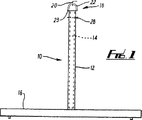
図1は、本発明による支持脚の側面図である。
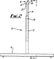
図2は、図1に示された支持脚の側面図であり、固定手段の高さを調節することができる態様を示す。
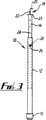
図3は、図2の線III−IIIに沿ってみた図である。
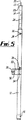
図4は、図1と同様の本発明の別の実施例の図1と同様の図である。
図5は、図3の線V−Vに沿ってみた図である。
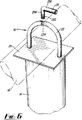
図6は、本発明の固定手段の拡大図である。
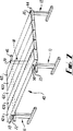
図7は、図1に示された複数の支持脚を組み入れたプラットホームの透視図である。
図8は、図7に示されたものの変型プラットホームの図である。
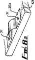
図8aは、図8の実施例に使用されるスリーブの拡大図である。
図9は、いろいろな高さの足場を有する図1及び2に示された支持システム(支持構造体)の側面図である。
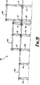
図10及び10Aは、階段に使用するための複数の支持脚から成る組立体の側面図である。
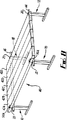
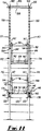
図11は、図10に示された支持組立体の正面図である。
実施例の説明
図1〜3を参照すると、第1直立部材12と該第1直立部内に摺動自在に受容された第2直立部材14とで構成された支持手段と、横部材16の形とした地面係合手段とから成る本発明の第1実施例による支持脚10が示されている。図1及び2に示されるように、支持脚10は逆T字の形である。支持脚10の高さは、図1のでは例えば、500mmと800mmの間で、又は、800mmと1400mmの間で調節することができるが、支持脚10は他の任意の適当な高さとすることができる。
支持脚10は、又、L字形ボルト20とU字形部材22とで構成した固定手段18(図6参照)を備えている。U字形部材22は、平坦プレート23に溶接され、平坦プレート23は第2直立部材14の上端に溶接されている。
別の実施例として、第2直立部材を省除してもよく、その場合は、平坦プレート23第1直立部材12の上端に溶接する。そのような実施例の支持脚10の高さは、例えば、500mm又は800mmとすることができるが、他の任意の適当な高さとすることができる。
図6にみられるように、L字形ボルト20は、第1部分20Aと第2部分20Bを有し、第2部分20Bの端部にねじ20Cが刻設されている。ボルト20のねじ付端部20Cは、U字形部材22に形成された対応するねじ穴22Aに螺入することができる。所望ならば、ボルト20のねじ付端部20Cを初めてねじ穴22Aに螺入する際、U字形部材22からのボルト20の抜けを防止するためにボルトの先行ねじ山を変形させることができる。
使用においては、細長部材又はバー44をU字形部材22のU字開口に通した後、ねじ付きボルト20をU字形部材22のねじ穴22Aにねじ込んでバー44に圧接させることによりバー44を固定手段18に固定する。バー44は、隣接する支持脚110の安定化手段29にまで延長させてそれに固定し、それによって両支持脚110を結合してそれらを安定化させることができる。
第2直立部材14は、上下方向に隔置された複数対の孔24を有している。各対の孔24は、互いに対向しているが、図3には各対の孔24の一方だけしか示されていない。第1直立部材12は、互いに対向した1対の孔26を有している。第2直立部材14の複数対の孔24のうちの所望の1対を第1直立部材12の1対の孔26に整列させれば、ピン28を4つの孔24,26のすべてに通すことができ、それによって第1直立部材12を第2直立部材14に錠止することができる。かくして、異なる対の孔24を孔26に整列させ、ピン28を用いて第1直立部材12を複数の異なる高さのうちの任意の高さで第2直立部材14に錠止することができ、したが、地面からの固定手段18の高さを調節することができる。
図4及び5を参照すると、本発明の第2実施例による支持脚110が示されている。この支持脚は、その第1直立部材12が図1〜3の第1実施例のものより長く、安定化手段29を備えているという点を除いては第1実施例の支持脚とほぼ同じである。安定化手段29は、直立部材12の上下両端間の中間部分に溶接されたプレート30と、プレート30に溶接された第2及び第3U字形部材32,34と、第2及び第3U字形部材32,34にそれぞれ螺入させることができる第2及び第3L字形ねじ付きボルト36,38とで構成されている。図から分かるように、U字形部材32,34及びL字形ねじ付きボルト36,38は、U字形部材22及びL字形ねじ付きボルト20と同様のものであり、同様の態様で機能する。
図7を参照すると、複数の支持脚10と、それらの支持脚によって支持された複数の板材即ちプラットホーム部材42A〜42Eとから成るプラットホーム40が示されている。第1板材42Aは他の板材42B〜42Eより厚い。支持脚10は、プラットホーム40の4隅に配置され、図7でみて手前側の1対の支持脚10の間にバー44が延設され、向う側の1対の支持脚10の間にバー46が延設される。バー44,46は、先に述べた固定手段18(図7には示されていない)によって各支持脚10に固定される。即ち、バー44,46の両端を支持脚10の対応するU字形部材22に通し、L字形ボルト20をU字形部材22にねじ込んでバー44,46に係合させ、それらのバーをそれぞれの支持脚10に固定する。
次いで、第1板材42Aをバー44,46の上に架け渡す。図7にみられるように、第1板材42Aの先行側縁に1対の孔50が穿設されている。これらの孔50には、それぞれ第1板材42Aを所定位置に固定するのに用いられるフェルール(金環)が嵌められている。先にバー44,46を支持脚10に固定する際、L字形ボルト20の第1部分20Aがプラットホームに向けて内側を指すようにU字形部材22に締め付けておく。かくして、第1板材42Aをバー44,46の上に載せて図7でみて左方へ滑らせると、各ボルト20の水平な第1部分20Aが摺動する第1板材42Aの先行側縁の孔50に嵌められたフェルールに受容される。次いで、残りの板材42B〜42Eを図7に示されるようにバー44,46の上に載せる。
残りの板材42B〜42Eを所定位置に保持するために、各板材の一方の側縁に第1及び第2孔が形成され、反対側の他方の側縁に第1及び第2突起が形成されている。1つの板材の第1及び第2突起をそれと隣接する板材の第1及び第2孔に挿入して両板材を結合することができるようになされている。バー44,46上の最終(図7でみて最右端)の板材42Eは、L字形ボルト20の第1部分20Aによって所定位置に保持される。即ち、板材42Eを所定位置に配置したならば、L字形ボルト20を締め付けてその第1部分20Aをプラットホーム40の方に内方に向け、板材42Eの上面に係合させる。プラットホーム40の使用者は、必要なだけの数の板材42を用いることができる。
図8及び8aは、図7に示されたプラットホームの変型例である。この変型例では、第1板材42Aも、他の板材42B〜42Eと同じ厚さとする。そして、第1板材42Aをの先行側縁に孔50を穿設する代わりに、第1板材42Aの上面にL字形ボルト20の第1部分20Aを受容するための1対のスリーブ50Aを設ける。スリーブ50Aの1つが図8に詳細に示されている。各スリーブ50Aは、例えばねじ51のような適当な締着手段又は接着剤によって板材42Aに取り付けることができる。
別法として、複数の板材42A〜42Eの代わりに、適当な幅の単一のプラットホーム部材を用いてることもできる。
図9は、バー44,46をいろいろな異なる高さに支持するように配置された複数の支持脚10から成る支持システム60を示す。バー46は、バー44(符号44A,44B,44Cで示されている)の真後にあるので図9ではみられない。この支持システム60は、例えば、座席を必要とする野外コンサートやショーに用いることができる。図9でみて左側の支持脚10Aは、最も低い座席を提供する。バー44A及び46A(図示せず)は、図7、8に示されるように板材のための支持部材を構成する。中央の支持脚10Bは、中間の高さの座席を提供し、バー44B及び46B(図示せず)は板材のための支持部材を構成する。図9でみて右側の支持脚10Cは、最も高い座席を提供し、バー44C及び46C(図示せず)は板材のための支持部材を構成する。バー44A,46Aは、支持脚10Aから支持脚10B及び10Cの安定化手段29を通して延設され、支持システム60の中央及び右側部分を安定化させる。
図9の左側の支持脚10Aは、図1、2に示されるような支持脚であり、その第2直立部材14を最下位置にしてある。中央の支持脚10Bは、図4、5に示されるような支持脚であり、その第2直立部材14をやはり最下位置にしてある。図9の右側の支持脚10Cは、図4、5に示されるような支持脚であり、その第2直立部材14を上昇位置にセットしてある。バー44,46の上に載せられる板材は、図を簡略するために省略されている。
本発明の範囲から逸脱することなくいろいろな変型が可能である。例えば、上述したU字形部材のU字形は、ほぼ正方形であってもよい。
変型実施例の更に別の1例は、例えば壁紙張り作業に適するようなベンチの一部として支持脚10を用いる例である。そのような例では、支持脚10の間に複数の板材42の代わりに単一のボード(板)を配設する。例えば壁紙張り作業に使用するには、そのようなボードは、幅2.5ft(76.2cm)、長さ5ft(152.4cm)とすることができる。ボードは、例えば3/4in(1.905cm)の厚さの合板で形成することができる。ボードの一方の面にその一方の長手側縁に近接したところにボードと同じ長さのフレーム材を接着剤又はねじによって付設する。フレーム材の厚さは2in(5.08cm)、幅は5in(12.7cm)とすることができる。ボードの該一方の面にその他方の長手側縁に近接したところにボードと同じ長さの合板ストリップを付設することができる。この合板ストリップの厚さは3/4in(1.905cm)、幅は3in(7.62cm)とすることができる。かくして、ボードの一方の面に、そのフレーム材と合板ストリップとの間に凹部が形成される。この凹部は、幅約22in(55.88cm)であり、壁紙のロールをそれに糊を塗布するために受容するのに十分な幅である。
ボードの一方の長手側縁には、L字形ボルト20の水平な第1部分20Aを受容するフェルールを嵌めるための2つの穴を穿設することができる。あるいは別法として、図8に示されるように、ボードの上面に一方の長手側縁に近接したところで、L字形ボルトの水平な第1部分20Aを受容するスリーブを取り付けてもよい。
図10、10A及び11を参照すると、本発明の更に別の変型例として、プラットホームを階段上に設置することを可能にする支持組立体110が示されている。支持組立体110は、前側(図10、10Aでみて右側)に配置される1対の支持脚112,114と、後側(図10、10Aでみて左側)に配置される1対の支持脚162,164とから成る。各支持脚112,114,162,164は、第1直立部材116と該第1直立部内に摺動自在に受容された第2直立部材117とから成る。第1直立部材116は、階段の1つの段120に係合するための横断部材又は段係合部材118に連結されている。各横断部材118の一端には、該横断部材を階段の段120に係合するための大きな表面を提供するプレート122が取り付けられている。
図から分かるように、各第1直立部材116は、その横断部材118が係合する段120の上方位置で該横断部材118から立上るように横断部材118の中心から偏倚した位置で横断部材118から延長している。
各第1直立部材116の、プレート122のある側とは反対側の端部には、支柱126を受容するようになされたU字形部材124が設けられている。(U字形部材124のU字形は、正方形又は円形であってもよい。)U字形部材124は、先に説明したU字形部材と同じであり、やはり先に説明したようになL字形とすることができるボルト128を受容するねじ孔を備えている。ボルト128は、U字形部材124のねじ孔にねじ込むことによって支柱126に係合させて支柱を横断部材118に固定することができ、それによってそれぞれの支持脚112,114を支持する。支柱126の側壁には、U字形部材124に追加の支持を与えるためにU字形部材124の下面に係合させることができるピン132を通すための複数の孔130を上下方向に間隔を置いて穿設することができる。
安定化部材134が支持脚112と114の間に延設され、それぞれの支持脚の第1直立部材116に付設されたU字形部材136,138によって各支持脚に固定される。U字形部材136,138は、先に説明したU字形部材32,34と同様のものであり、同様の態様で機能する。
控え部材144が、各直立部材116から斜め下方へ横断部材118によって係合されている段120の上の段146にまで延設されている。直立部材116に対する控え部材144の角度は、30゜〜60゜の範囲である。
各直立部材116には、対応する控え部材144を受容するように斜めに角度を付された第4U字形部材147が付設されており、各控え部材144をそれぞれ対応する第4U字形部材147に固定するためのボルト148が設けられている。
各第2直立部材117は、上下方向に隔置された複数対の対向した孔150を有している。第1直立部材116は、互いに対向した1対の孔152を有している。第2直立部材117の複数対の孔150のうちの所望の1対を第1直立部材116の1対の孔152に整列させて、ピン154をそれらの孔に通すことにより第1直立部材116を第2直立部材117に対して所望の位置に錠止することができる。かくして、第2直立部材117の上端の高さを調節することができる。
図6及び7に示されるバー44と同様の態様で2つの支持脚112と114と間に延設されるバー158を受容するためのU字形部材156が各第2直立部材117の上端に溶接されている。バー158は、先にバー44に関連して説明したのと同様の態様で、L字形ボルト160をU字形部材156のねじ孔に螺入することによって支持脚112,114に固定することができる。
追加の対の支持脚162,164が、段120より高い段166上に立設される。追加の対の支持脚162,164も、支持脚112,114と同じであり、同じ部材は同じ参照番号で示されている。追加の対の支持脚162,164の第2直立部材117の高さは、その上端のU字形部材156が、支持脚112,114の第2直立部材117の上端のU字形部材156と同じ高さとなるように調節される。
第1対の支持脚112,114のバー158と追加の対の支持脚162,164のバー158との間に複数の板材166が架け渡され、図8、8aの実施例の場合と同様に、両側の板材166の上面に付設された適当なスリーブにL字形ボルト160を係合させることによって板材を所定位置に保持する(図10A参照)。
板材166に追加の支持を与えるために更に1対の支持脚10(先に説明した支持脚10と同様のもの)を階段の頂部踊り場170に立設することができる。支持脚10と10の間にバー44を延設し、それらのバーの上に板材166を載せることができる。かくして、階段に設置されたプラットホーム(2つの支持組立体110とそれらの間に架け渡された板材166から成る)へ踊り場170からアクセスすることができる。図10Aの例では、支持脚10と、図10Aでみて最右側の支持組立体110との間に追加の支持組立体110が設けられているが、支持脚10と最右側の支持組立体110との間の距離が余り長くない場合は、支持脚10の最右側の支持組立体110との間の中間に追加の支持組立体110を設ける必要がない。
支持脚10を運ぶために、細長部材44と同様の断面形状の短い管を用いることができる。図8及び8aにみられるように、複数の、例えば4つの支持脚10が設けられる例は多々ある。その場合、短い管を各支持脚10のU字形部材22に挿入し、ボルト20をねじ込んで該短い管に圧着させて固定することができる。かくして、4つの支持脚10をまとめて運ぶためにボルト20をハンドルとして用いることができる。
上述した本発明の支持脚の1つの利点は、多種多様の目的のためのプラットホームを構成することができることである。例えば、本発明の支持脚によって構築されたプラットホームは、作業ベンチ、トレッスル、床、屋台、仮設座席のための棚等として使用することができる。ここに挙げた用途の例は、すべての用途を網羅したものではなく、本発明の支持脚を応用することができる用途は他にも多々存在することは明らかであろう。 TECHNICAL FIELD The present invention relates to a support leg.
Technical background Plasterers and builders often require some form of platform to reach the ceiling, for example.
Various forms of platforms are used for this purpose, such as using a trestle on which an operator can stand, or if a trestle is not available, such as a wooden frame or A ready-to-use platform can be constructed using wood board. However, such a structure is not satisfactory because it is unstable and lacks strength.
DISCLOSURE OF THE INVENTION An object of the present invention is to eliminate or mitigate these disadvantages of the prior art.
In accordance with one aspect of the present invention, it comprises an upright member and a securing means for securing the elongate member to the upright member, wherein the elongate member is secured to the upright member to define at least a portion of the platform. The platform member can be supported on the elongated member, and the fixing means includes a fixing position for fixing the elongated member to the upright member, and removing the elongated member from the upright member. A platform is provided that is movable between an unfixed position allowing.
Preferably, the securing means comprises a projecting member adapted to engage the platform member and hold the platform member on the elongated member when it is brought into the secured position. The projecting member is an elongated member so that it can project transversely from the upright member when the securing means is brought into the secured position.
The securing means is preferably configured to receive the elongate member and may be in the form of a U-shaped member to receive one end portion of the elongate member. For example, the U-shaped member may be curved to receive an elongated member that is substantially cylindrical in cross section. Alternatively, the U-shape of the U-shaped member can be square or rectangular to receive an elongated member having a substantially square or rectangular cross-sectional shape.
The U-shaped member may be formed with a screw hole that engages with the elongated member received in the U-shaped member and is screwed with a bolt for fixing the elongated member. The bolt may have a shape having a first threaded portion and a second portion extending in a transverse direction from the first threaded portion, and the second portion may constitute the protruding member. The bolt is preferably substantially L-shaped.
The present invention is particularly suitable for use in combination with elongate members, for example in the form of cylindrical bars or rectangular bars.
At least one side edge of the platform member is formed with a plurality of holes capable of receiving the protruding member, and the platform member is inserted into the hole of the platform member by inserting the protruding member into the elongated member. It can be configured to be held on top. Alternatively, a plurality of sleeves capable of receiving the projecting member are attached to at least one upper surface of the platform member, and the platform member is inserted into the sleeve of the platform member by inserting the projecting member into the sleeve. It can comprise so that it can hold | maintain on a member.
The U-shaped member can be attached to the substantially flat plate at both ends, preferably by welding, and the flat plate can also be attached to the upright member, preferably also by welding.
One end of the upright member is preferably attached to the ground engaging means. The fixing means can be attached to the other end of the upright member.
Alternatively, the support leg comprises a first upright member and a second upright member slidably received in the first upright member, and the first upright member is attached to the ground engaging means, The second upright member is configured such that it can be locked to the first upright member at any one of a desired number of positions along its length. For that purpose, a pair of mutually opposing holes is formed in the first upright member member, and the holding member for holding the second upright member in the arbitrary one position is the pair of first upright members. It can be made to be able to be inserted through the hole. This holding member can be in the form of a pin. A plurality of pairs of holes are formed in the second upright member at intervals along the length thereof, and each pair of holes is opposed to each other so that the pin can be inserted therethrough. Thus, the second upright member can be raised and lowered as desired, and selectively positioned so that the desired pair of holes in the second upright member are aligned with the holes in the first upright member, thereby The pins can be inserted through the holes of the first and second upright members to lock both upright members. The pin can be provided with a spring clip for securing it to the first upright member.
The first upright member is preferably rectangular in cross section, and the second upright member is preferably circular in cross section. The upper edge of the first upright member can be bent (crimped) radially inward to stabilize (stablely hold) the second upright member.
Stabilization means may be provided for stabilizing the support legs during use. Preferably, the stabilizing means is constituted by a second (another) fixing means attached to a central portion between the upper and lower ends of the upright member. The stabilizing means is preferably constituted by two second fixing means adjacent to each other, and an elongated member in addition to the second fixing means is inserted.
According to another aspect of the present invention, two pairs of the above-described support legs are provided, an elongated member is extended between the first pair of support legs and the second pair of support legs, and the elongated members are interposed between them. A platform constructed by spanning at least one platform member. The elongated member is fixed to the support leg by the fixing means.
The platform can be composed of a plurality of platform members arranged adjacent to each other, and each platform member is provided with cooperative means comprising corresponding holes and protrusions, and the platform members in which the holes of each platform member are adjacent to each other. The platform members can be configured to be held in a coupled state in cooperation with the projections.
First and second holes are formed at intervals along one side edge of each platform member, and first and second protrusions are formed at intervals along the other side edge, and the protrusions of each platform member are formed. Can be configured to be received in the holes of adjacent platform members.
Alternatively, a sleeve for receiving a portion of the securing means may be provided on the upper surface of the platform member to be placed adjacent to the support leg.
The platform member may be in the form of an elongated planar member such as a plate.
According to yet another aspect of the invention, a support assembly is provided for use in forming a platform on a staircase. The support assembly supports the above-described support leg, a step engagement member that is engaged with one step of the step at one end, and the step engagement member at a position spaced from the one end. And an elongated member such as a column that is adjustably fixed to the step engaging member.
The upright member of the support leg can be extended from the step engagement member at a portion between one end and the other end of the step engagement member. It is preferable to provide the 2nd fixing means for fixing the said support | pillar at the other end of the step engaging member. The second securing means can be configured to receive the struts.
The support assembly is provided with third fixing means for fixing the third elongated member constituting the stabilizing member to the upright member, and the similar supporting assembly is adjacent to the supporting assembly. It can be extended to. It is preferred to provide two third securing means that can be attached to the plate.
The stay member can be fixed to the upright member of the support leg. The retaining member can be extended from the upright member to the step. The holding member is preferably an elongated member, and is conveniently fixed to the upright member by the fourth fixing means. The fourth fixing means can be disposed obliquely so that the retaining member extends from the upright member at an angle of 10 ° to 80 °, preferably 30 ° to 60 °. The support assembly may include the first upright member and the second upright member described above.
The fixing means and the second, third and fourth fixing means are preferably U-shaped such as circular, square or rectangular so as to receive the corresponding elongated members.
The U-shaped member of each securing means has a threaded hole for receiving a bolt, which may be L-shaped and configured to engage the corresponding elongated member. preferable.
[Brief description of the drawings]
FIG. 1 is a side view of a support leg according to the present invention.
FIG. 2 is a side view of the support leg shown in FIG. 1 and shows a mode in which the height of the fixing means can be adjusted.
FIG. 3 is a view taken along line III-III in FIG.
4 is a view similar to FIG. 1 of another embodiment of the present invention similar to FIG.
FIG. 5 is a view taken along line VV in FIG.
FIG. 6 is an enlarged view of the fixing means of the present invention.
FIG. 7 is a perspective view of a platform incorporating the plurality of support legs shown in FIG.
FIG. 8 is a diagram of a modified platform of that shown in FIG.
FIG. 8a is an enlarged view of the sleeve used in the embodiment of FIG.
FIG. 9 is a side view of the support system (support structure) shown in FIGS. 1 and 2 having scaffolds of various heights.
10 and 10A are side views of an assembly of a plurality of support legs for use in stairs.
FIG. 11 is a front view of the support assembly shown in FIG.
Description of the embodiment Referring to Figs. 1-3, a support means comprising a
The
As another example, the second upright member may be omitted, in which case the
As shown in FIG. 6, the L-shaped
In use, after passing the elongated member or
The
4 and 5, a
Referring to FIG. 7, there is shown a
Next, the
In order to hold the remaining
8 and 8a are variations of the platform shown in FIG. In this modified example, the
Alternatively, a single platform member with an appropriate width may be used in place of the plurality of
FIG. 9 shows a
The
Various modifications are possible without departing from the scope of the invention. For example, the U-shape of the U-shaped member described above may be substantially square.
Yet another example of a variant embodiment is an example in which the
Two longitudinal holes for receiving a ferrule for receiving the horizontal
Referring to FIGS. 10, 10A and 11, as yet another variation of the present invention, a
As can be seen, each first
A
A stabilizing
A retaining
Each
Each of the second
A
Additional pairs of
A plurality of
An additional pair of support legs 10 (similar to the
In order to carry the
One advantage of the support legs of the present invention described above is that a platform for a wide variety of purposes can be constructed. For example, a platform constructed with the support legs of the present invention can be used as a work bench, trestle, floor, stall, shelf for temporary seats, and the like. It will be apparent that the examples of applications listed here are not exhaustive and that there are many other applications where the support legs of the present invention can be applied.
Claims (35)
支持脚は、支持手段と、細長部材を支持手段に固定するための固定手段とを備え、
固定手段は、細長部材を支持手段に固定する固定位置と、細長部材が支持手段から外され得る非固定位置との間を移動自在であり、
固定手段は、該固定手段が固定位置にある際、プラットホーム部材に係合して該プラットホーム部材を細長部材上に保持し得るようになされた突出部を備えることを特徴とするプラットホーム。A platform comprising a support leg, an elongate member that can be secured to the support leg, and a platform member that can be supported on the elongate member,
The support leg includes support means and fixing means for fixing the elongated member to the support means,
The fixing means is movable between a fixing position for fixing the elongated member to the supporting means and an unfixed position where the elongated member can be removed from the supporting means,
The platform comprises a protrusion adapted to engage the platform member to hold the platform member on the elongated member when the securing means is in the locked position.
固定手段は、細長部材を受け入れる成形部材を含み、
成形部材は、細長部材の周囲に延長する部分を有し、
固定手段は、ボルトを更に含み、
成形部材は、該成形部材に受け入れられた細長部材に係合する前記ボルトを受け入れるねじ孔をも規定し、
前記ボルトは、細長部材及びプラットホーム部材を支持脚に固定する固定位置と、細長部材及びプラットホーム部材が支持脚から外され得る非固定位置との間を移動自在であり、
前記ボルトは、第1ねじ部分と該第1ねじ部分から横断方向に伸長する第2部分とを備え、
第2部分は、細長部材上方において伸長する突出部を成し、かつ、該突出部は、ボルトが固定位置にある際、プラットホーム部材に係合して該プラットホーム部材を細長部材上に保持し得ることを特徴とするプラットホーム。A platform comprising a support leg, an elongate member that can be fixed to the support leg, a platform member that can be supported on the elongate member, and a fixing means for fixing the elongate member and the platform member to the support leg,
The securing means includes a molded member that receives the elongated member,
The molded member has a portion extending around the elongated member,
The fixing means further includes a bolt,
The molded member also defines a screw hole for receiving the bolt that engages an elongated member received in the molded member;
The bolt is movable between a fixed position for fixing the elongated member and the platform member to the support leg and a non-fixed position where the elongated member and the platform member can be detached from the support leg,
The bolt includes a first threaded portion and a second portion extending transversely from the first threaded portion,
The second portion comprises a protrusion that extends above the elongate member, and the protrusion may engage the platform member to hold the platform member on the elongate member when the bolt is in a fixed position. A platform characterized by that.
複数の支持組立体と、第1及び第2細長部材と、複数のプラットホーム部材とを備え、
各支持組立体は、支持手段と、細長部材を支持手段に固定するための固定手段とを含み、
細長部材が支持手段に固定される際、プラットホーム部材は、プラットホームの少なくとも一部を形成するため、細長部材上に支持され得、
固定手段は、細長部材を支持手段に固定する固定位置と、細長部材が支持手段から外され得る非固定位置との間を移動可能であり、
各支持組立体は、そこから支持手段が伸長する段係合部材を含み、
段係合部材は、第1及び第2端部を有し、第1端部は階段に係合するようになされ、
支持組立体は、段係合部材を、その第1端部から離隔した位置で支持するため、段係合部材に調節自在に固定されるようになされた支柱を更に含むことを特徴とするプラットホーム。A platform for use on stairs,
A plurality of support assemblies, first and second elongated members, and a plurality of platform members;
Each support assembly includes support means and securing means for securing the elongated member to the support means;
When the elongate member is secured to the support means, the platform member may be supported on the elongate member to form at least a portion of the platform;
The fixing means is movable between a fixing position for fixing the elongated member to the supporting means and an unfixed position where the elongated member can be removed from the supporting means,
Each support assembly includes a step engagement member from which support means extends,
The step engaging member has first and second ends, and the first end is adapted to engage the step.
The support assembly further includes a strut adapted to be adjustably secured to the step engagement member for supporting the step engagement member at a position spaced from the first end thereof. .
Applications Claiming Priority (3)
| Application Number | Priority Date | Filing Date | Title |
|---|---|---|---|
| GB929215594A GB9215594D0 (en) | 1992-07-22 | 1992-07-22 | Improvements in or relating to supports |
| GB9215594.4 | 1992-07-22 | ||
| PCT/GB1993/001546 WO1994002698A1 (en) | 1992-07-22 | 1993-07-22 | Improvements in or relating to support legs |
Publications (2)
| Publication Number | Publication Date |
|---|---|
| JPH07509293A JPH07509293A (en) | 1995-10-12 |
| JP3616640B2 true JP3616640B2 (en) | 2005-02-02 |
Family
ID=10719121
Family Applications (1)
| Application Number | Title | Priority Date | Filing Date |
|---|---|---|---|
| JP50429894A Expired - Fee Related JP3616640B2 (en) | 1992-07-22 | 1993-07-22 | Support legs |
Country Status (7)
| Country | Link |
|---|---|
| EP (1) | EP0653008B1 (en) |
| JP (1) | JP3616640B2 (en) |
| AT (1) | ATE158373T1 (en) |
| AU (1) | AU678984B2 (en) |
| DE (1) | DE69314039T2 (en) |
| GB (1) | GB9215594D0 (en) |
| WO (1) | WO1994002698A1 (en) |
Families Citing this family (3)
| Publication number | Priority date | Publication date | Assignee | Title |
|---|---|---|---|---|
| WO1996004442A1 (en) * | 1994-08-01 | 1996-02-15 | David Ian Seale | Improvements in or relating to connectors |
| US10061323B2 (en) * | 2016-12-22 | 2018-08-28 | Advanced Construction Robotics, Inc. | Autonomous apparatus and system for repetitive tasks in construction project |
| DE202017006416U1 (en) | 2017-12-13 | 2017-12-19 | Thomas Haak | small frame |
Family Cites Families (8)
| Publication number | Priority date | Publication date | Assignee | Title |
|---|---|---|---|---|
| FR559494A (en) * | 1922-12-07 | 1923-09-15 | Scaffolding support | |
| US2299823A (en) * | 1941-08-14 | 1942-10-27 | Juculano Theodor Charles | Adjustable scaffolding |
| GB737637A (en) * | 1953-10-31 | 1955-09-28 | Joshua Roscoe Marsden | Improvements in builders scaffolding trestles |
| US3080015A (en) * | 1961-06-28 | 1963-03-05 | Howard Van Devender | Demountable bench |
| US3175642A (en) * | 1961-12-28 | 1965-03-30 | Perry E Neeley | Knockdown scaffold |
| US3547227A (en) * | 1969-08-25 | 1970-12-15 | Herbert F Trevino | Sawhorse trestle |
| AU7878775A (en) * | 1974-03-15 | 1976-09-09 | Preston J C | Scaffolding system |
| US4371057A (en) * | 1980-12-16 | 1983-02-01 | 100426 Canada Ltee. | Telescopic scaffold |
-
1992
- 1992-07-22 GB GB929215594A patent/GB9215594D0/en active Pending
-
1993
- 1993-07-22 JP JP50429894A patent/JP3616640B2/en not_active Expired - Fee Related
- 1993-07-22 DE DE69314039T patent/DE69314039T2/en not_active Expired - Lifetime
- 1993-07-22 WO PCT/GB1993/001546 patent/WO1994002698A1/en not_active Ceased
- 1993-07-22 AU AU47148/93A patent/AU678984B2/en not_active Ceased
- 1993-07-22 AT AT93917890T patent/ATE158373T1/en not_active IP Right Cessation
- 1993-07-22 EP EP93917890A patent/EP0653008B1/en not_active Expired - Lifetime
Also Published As
| Publication number | Publication date |
|---|---|
| DE69314039T2 (en) | 1998-02-12 |
| EP0653008B1 (en) | 1997-09-17 |
| EP0653008A1 (en) | 1995-05-17 |
| AU4714893A (en) | 1994-02-14 |
| JPH07509293A (en) | 1995-10-12 |
| AU678984B2 (en) | 1997-06-19 |
| WO1994002698A1 (en) | 1994-02-03 |
| DE69314039D1 (en) | 1997-10-23 |
| ATE158373T1 (en) | 1997-10-15 |
| GB9215594D0 (en) | 1992-09-02 |
Similar Documents
| Publication | Publication Date | Title |
|---|---|---|
| US3229790A (en) | Tensioned frame structure | |
| US5954156A (en) | Adjustable saw horse | |
| US4638604A (en) | Staging structure | |
| US6123209A (en) | Rack | |
| US5845795A (en) | Storage rack and bracket for same | |
| US9814308B2 (en) | Leg assembly | |
| US6419204B1 (en) | Outside conversion corner for form work | |
| US3934676A (en) | Scaffold structure | |
| US5086875A (en) | Folding scaffold | |
| US10905234B1 (en) | Overhead storage system and method | |
| US10646035B1 (en) | Overhead storage system and method | |
| US2988181A (en) | Scaffolds | |
| JP3616640B2 (en) | Support legs | |
| US2297316A (en) | Scaffolding support | |
| US3186668A (en) | Shelf unit support | |
| US6761249B2 (en) | Support such as a trestle or a stepladder | |
| US3858682A (en) | Saw horse construction | |
| US3613832A (en) | Scaffolding | |
| WO2012064204A2 (en) | A scaffold and method for construction of same | |
| US20050077108A1 (en) | Horizontal support member for tube and clamp scaffold assembly | |
| US3265155A (en) | Extensible ladder and support | |
| WO1992020886A1 (en) | Scaffold planking stabilizer | |
| CN214885305U (en) | Scaffold with adjustable base | |
| WO1996032553A1 (en) | Working platform assembly | |
| US5868220A (en) | Support legs |
Legal Events
| Date | Code | Title | Description |
|---|---|---|---|
| A711 | Notification of change in applicant |
Free format text: JAPANESE INTERMEDIATE CODE: A711 Effective date: 20040720 |
|
| TRDD | Decision of grant or rejection written | ||
| A01 | Written decision to grant a patent or to grant a registration (utility model) |
Free format text: JAPANESE INTERMEDIATE CODE: A01 Effective date: 20041012 |
|
| A61 | First payment of annual fees (during grant procedure) |
Free format text: JAPANESE INTERMEDIATE CODE: A61 Effective date: 20041108 |
|
| R150 | Certificate of patent or registration of utility model |
Free format text: JAPANESE INTERMEDIATE CODE: R150 |
|
| FPAY | Renewal fee payment (event date is renewal date of database) |
Free format text: PAYMENT UNTIL: 20081112 Year of fee payment: 4 |
|
| FPAY | Renewal fee payment (event date is renewal date of database) |
Free format text: PAYMENT UNTIL: 20091112 Year of fee payment: 5 |
|
| FPAY | Renewal fee payment (event date is renewal date of database) |
Free format text: PAYMENT UNTIL: 20101112 Year of fee payment: 6 |
|
| LAPS | Cancellation because of no payment of annual fees |