JP3614583B2 - Shifting operation input device for automatic transmission - Google Patents
Shifting operation input device for automatic transmission Download PDFInfo
- Publication number
- JP3614583B2 JP3614583B2 JP28001796A JP28001796A JP3614583B2 JP 3614583 B2 JP3614583 B2 JP 3614583B2 JP 28001796 A JP28001796 A JP 28001796A JP 28001796 A JP28001796 A JP 28001796A JP 3614583 B2 JP3614583 B2 JP 3614583B2
- Authority
- JP
- Japan
- Prior art keywords
- range
- shift
- shift lever
- ranges
- display
- Prior art date
- Legal status (The legal status is an assumption and is not a legal conclusion. Google has not performed a legal analysis and makes no representation as to the accuracy of the status listed.)
- Expired - Fee Related
Links
Images


Classifications
-
- F—MECHANICAL ENGINEERING; LIGHTING; HEATING; WEAPONS; BLASTING
- F16—ENGINEERING ELEMENTS AND UNITS; GENERAL MEASURES FOR PRODUCING AND MAINTAINING EFFECTIVE FUNCTIONING OF MACHINES OR INSTALLATIONS; THERMAL INSULATION IN GENERAL
- F16H—GEARING
- F16H63/00—Control outputs from the control unit to change-speed- or reversing-gearings for conveying rotary motion or to other devices than the final output mechanism
- F16H63/40—Control outputs from the control unit to change-speed- or reversing-gearings for conveying rotary motion or to other devices than the final output mechanism comprising signals other than signals for actuating the final output mechanisms
- F16H63/42—Ratio indicator devices
Landscapes
- Arrangement And Mounting Of Devices That Control Transmission Of Motive Force (AREA)
- Arrangement Or Mounting Of Control Devices For Change-Speed Gearing (AREA)
- Control Of Transmission Device (AREA)
Description
【0001】
【発明の属する技術分野】
本発明は、自動変速機、特に変速段を自動的に切り換えるDレンジ等の他に、シフトレバーの揺動操作により変速段を切り換えるマニュアルレンジ(以下、Mレンジという)を有する自動変速機の変速操作入力装置に関する。
【0002】
【従来の技術】
近年、車両用の自動変速機として、変速段を自動的に切り換えるDレンジ等の他に手動操作で変速段を切り換えるMレンジを備えたものが実用化されつつあり、このような自動変速機として、例えば特開平4−244655号公報に開示されたものがある。
【0003】
この自動変速機においては、車体前後方向の第1のシフトゲート内でシフトレバーの揺動操作によって、P(駐車)、R(後退)、N(中立)、D(ドライブ)、3(3速)、2(2速)、1(1速)のレンジが選択可能とされていると共に、上記Dレンジの選択位置から横方向に延びるゲートを介してMレンジ用として第1のシフトゲートに平行な第2のシフトゲートが設けられている。そして、この第2のシフトゲート内においてシフトレバーを中立位置に付勢すると共に、この中立位置から前方へ操作すると変速段が1段シフトアップし、後方へ操作すると変速段が1段シフトダウンするように構成されている。
【0004】
ところで、上記のように、通常のレンジ選択用の第1のシフトゲートの横にMレンジ用の第2のシフトゲートを設けた場合、シフトゲートの全体形状ないしシフトレバーの動作領域の幅が広くなると共に、これに伴って変速操作装置の全体としても横方向に寸法が大きくなる。そのため、車体への取り付けに支障を来したり、周辺機器との間のレイアウトを困難にしたりすることになる。
【0005】
これに対しては、車体前後方向に並ぶ各レンジの選択位置の列の一端にMレンジの選択位置を配置し、シフトレバーをこの列の当該端部まで操作したときにMレンジが選択されると共に、このMレンジの選択位置内におけるシフトレバーの前後方向の操作により変速段がシフトアップもしくはシフトダウンされるように構成することが考えられる。これによれば、シフトレバーは前後方向に直線状に移動するだけとなって、該シフトレバーの動作領域の幅が狭くなり、これに伴って変速操作装置の横方向寸法も抑制されることになる。
【0006】
一方、この種の自動変速機の変速操作入力装置においては、シフトレバーの操作線の側方に現在の選択レンジを示す表示機構が設けられるが、この機構は一般に次のように構成される。
【0007】
つまり、図12に示すように、シフトレバーAが車体側に固定されたカバー部材Bの開口部B1内で車体前後方向に揺動操作され、かつ、この開口部B1が、シフトレバーAに取り付けられて上記カバー部材Bの下方で該レバーAの操作方向にスライド可能とされたスライドプレートCによって閉鎖されている構成において、上記スライドプレートCの一側部に選択位置表示用の突出部C1を設けて、該突出部C1に所定の色彩を施すと共に、上記カバー部材Bには、このスライドプレートCの突出部C1を露出させるレンジ数と同数の表示窓Bp,Br,Bn,Bd,Bmを設けて、各表示窓Bp〜Bmに当該レンジを示す文字を付す。そして、図示のように、例えばシフトレバーAがMレンジに操作されている場合には、スライドプレートCの突出部C1がカバー部材BにおけるMレンジ用の表示窓Bmの下方に位置して、このMレンジ用の表示窓Bmに他の表示窓Bp〜Bdとは異なる色彩が表示されるように構成するのである。
【0008】
【発明が解決しようとする課題】
ところで、上記のような選択レンジの表示機構を、前述のようなレンジ選択位置直列配置の自動変速機、即ちシフトレバーの揺動操作によるMレンジを含む複数のレンジの選択位置が一列に配置され、かつ、Mレンジ内でのシフトレバーの揺動操作が上記列の方向に沿って行われるように構成された自動変速機に適用した場合、次のような不具合の発生が考えられる。
【0009】
つまり、図12に示すように、Mレンジでは、変速段をシフトアップまたはシフトダウンさせるためにシフトレバーAが一定範囲xで前後方向に操作されるが、その間、カバー部材AにおけるMレンジ用表示窓Bmの全体に常にスライドプレートCの突出部C1の色彩が表示されるようにするためには、この突出部C1の前後方向の寸法を十分に長くしなければならないことになる。
【0010】
しかし、このようにすると、図Aに鎖線アで示すように、例えばシフトレバーAがNレンジに操作された場合に、Nレンジ用表示窓Bnとこれに隣接するレンジの表示窓Br,Bdとの間隔に対して上記スライドプレートCの突出部C1の前後方向の寸法が大きくなりすぎ、隣接する表示窓Br,Bdの一部に突出部C1の色彩が露出し、見栄えが悪化することになる。また、これを防止しようとして、突出部C1の前後方向の寸法を短くすれば、Mレンジ内での操作時に、Mレンジ用表示窓Bmの一部に突出部C1の着色されている部分が存在しなくなり、この場合も見栄えが悪化することになる。
【0011】
これに対しては、スライドプレートの突出部の前後方向の寸法を長くすると共に、カバー部材における各表示窓間の間隔を十分長くすればよいが、この場合、例えばNレンジとこれに隣接するDレンジやRレンジとの間でのシフトレバーのストロークが長くなり、これに伴って操作性の悪化や当該変速操作入力装置の前後方向寸法の増大等の種々の不都合を招くことになる。
【0012】
本発明に係る変速操作入力装置は、Mレンジを有する自動変速機における上記のような実情に対処するものであり、操作性の悪化や当該変速操作入力装置の前後方向寸法の増大等を招くことなく、Mレンジ及びその他のレンジについての選択表示を良好に行い得るようにすることを課題とする。
【0013】
【課題を解決するための手段】
上記課題を解決するため、本発明では次のような手段を用いる。
【0014】
まず、本願の特許請求の範囲の請求項1に記載した発明(以下、第1発明という)は、シフトレバーを所定方向に揺動させることにより、変速段を手動操作で切り換えるMレンジを含む複数のレンジを有し、シフトレバーによるこれらのレンジの選択位置が一列に配置されていると共に、Mレンジ内での上記手動変速操作が上記列の方向に沿って行われるように構成された自動変速機において、上記シフトレバーに連動して該レバーの操作方向にスライドし、かつ一側部に選択位置表示用突出部が設けられたスライドプレートと、該プレートの上方を覆うように車体側に取り付けられ、かつ上記スライドプレートの突出部を露出させるレンジ数と同数の表示窓がシフトレバーの各レンジ選択位置に対応させて設けられたカバー部材とを備えると共に、該カバー部材における上記Mレンジ用表示窓を他のレンジ用の表示窓の列に対してシフトレバーの操作方向と直交する方向にオフセットし、かつ、上記スライドプレートにおける表示用突出部を、シフトレバー操作方向の寸法が長いMレンジ用突出部と同方向の寸法が短い他のレンジ用の突出部とで構成し、これらの突出部を、上記表示窓のオフセットに対応させてスライドプレートの当該側部に二段に突出させたことを特徴とする。
【0015】
また、請求項2に記載した発明(以下、第2発明という)は、上記第1発明において、複数のレンジの選択位置として、P、R、N、D、Mの各レンジの選択位置をシフトレバーの操作方向に沿って一列に配置すると共に、カバー部材の表示窓を、P、R、N、Dレンジ用のものが一列に、Mレンジ用のものがこれらに対してオフセットされるように設けたことを特徴とする。
【0016】
さらに、請求項3に記載した発明(以下、第3発明という)は、同じく第1発明において、カバー部材における表示窓を、Mレンジ用のものが他のレンジ用のものに対してシフトレバーの操作線に近い方にオフセットすると共に、これに対応させて、スライドプレート側部の表示用突出部もMレンジ用突出部をシフトレバーの操作線に近い方に設けたことを特徴とする。
【0017】
上記の手段を用いることにより、本願各発明はそれぞれ次のように作用する。
【0018】
まず、第1発明〜第3発明のいずれによっても、カバー部材におけるMレンジ用の表示窓と他のレンジ用表示窓とがシフトレバーの操作方向と直交する方向にオフセットされ、かつ、このオフセットに対応させて、スライドプレートのMレンジ用突出部と他のレンジ用の突出部とが該スライドプレートの当該側部に二段に突出させた状態で設けられているから、Mレンジ用突出部は、MレンジにおいてMレンジ用の表示窓に表示される以外、他の表示窓に表示されることがなくなる。そして、このMレンジ用突出部のシフトレバー操作方向の寸法は長いので、Mレンジ内では、シフトレバーのシフトアップまたはシフトダウンの操作を行っても、該Mレンジ用突出部が常にMレンジ用表示窓の全体に表示されている状態が維持されることになる。
【0019】
また、スライドプレートにおけるMレンジ以外の他のレンジ用の突出部はシフトレバー操作方向の寸法が短いので、Mレンジ以外の他のレンジで、当該他のレンジ用表示窓以外の表示窓にも突出部が露出することが防止される。
【0020】
そして、第2発明によれば、上記第1発明の作用が、複数のレンジとして、P、R、N、D、Mの各レンジを有し、これらのレンジの選択位置がシフトレバーの操作方向に沿って一列に配置された自動変速機において得られることになる。
【0021】
さらに、第3発明によれば、カバー部材におけるMレンジ用の表示窓が他のレンジ用の表示窓に対してシフトレバーの操作線に近い方にオフセットされていると共に、これに対応させて、二段に突出されるスライドプレート側部の表示用突出部も、シフトレバー操作方向の寸法が長いMレンジ用突出部がシフトレバーの操作線に近い方に設けられ、したがって、スライドプレートの一側部に、その側辺に沿う方向の寸法が長い突出部が、さらにその外側辺に同方向の寸法が短い突出部が設けられることになって、表示用突出部の全体形状が、基端側が太く、先端側が細い安定した形状となる。
【0022】
【発明の実施の形態】
以下、本発明の実施の形態について説明する。
【0023】
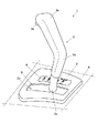
図1は、この実施の形態に係る変速操作入力装置1の外観を示すもので、当該自動車の運転席側方の車体部材Xにはカバー2が取り付けられ、該カバー2に設けられた前後方向に細長い開口部2aからシフトレバー3の上部が突出されている。
【0024】
このシフトレバー3は、上記カバー2の開口部2aに沿って前後方向に操作されて、その操作位置により、前方からPレンジ、Rレンジ、Nレンジ、Dレンジ及びMレンジが選択されるようになっている。また、Mレンジの操作位置には、中立位置を中心として前後にシフトアップ位置及びシフトダウン位置がそれぞれ設けられている。そして、これらの操作位置を示す表示板4が上記カバー2における開口部2aの側方に設けられていると共に、該開口部2aは、シフトレバー3に係合されて該レバー3の操作に従って前後にスライドするスライドプレート5によって閉鎖されている。
【0025】
なお、このシフトレバー3は、パイプ部材3aによって本体が構成されていると共に、その中間部より上方の部分は被覆部材3bで覆われており、また上端の操作部3cには、シフト操作に対する規制を解除するための規制解除ボタン3dが設けられている。
【0026】
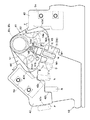
次に、変速操作入力装置1の上記カバー2より下方に配置された部分の構造を説明すると、図2及び図3に示すように、この装置1は、合成樹脂で成形されて、前後4か所のボルト穴11……11に挿通されるボルト(図示せず)により車体に取り付けられるベース部材10を有する。
【0027】
このベース部材10の中央部には下方へ突出する中空箱状の突出部12が設けられ、この突出部12の左右両側面に孔12a,12aが設けられていると共に、上記シフトレバー3を構成するパイプ部材3aの下端部には、逆T字状(図4参照)をなすように横方向に延びる同じくパイプ部材でなる支軸3eが固着されており、この支軸3eの左右両端部が上記突出部12の孔12a,12aにそれぞれ嵌合されて、シフトレバー3が該突出部12ないしベース部材10に前後に揺動可能に支持されている。
【0028】
そして、このベース部材10上には、シフトレバー3の位置決め機構、該シフトレバー3の各レンジ間での操作を規制する操作規制機構、該シフトレバー3がMレンジに操作されたことを検出するMレンジスイッチの操作機構、Mレンジ内におけるシフトレバー3に対する中立付勢機構及びシフトアップ、シフトダウン操作を検出するシフトアップスイッチ及びシフトダウンスイッチの操作機構等が配設されている。
【0029】
上記位置決め機構は、ベース部材10に設けられた位置決め部13と、シフトレバー3に取り付けられた位置決め用板バネ部材14とで構成されている。このうち、位置決め部13は、ベース部材10の上面中央部におけるシフトレバー3の突出部の前方に該ベース部材10に一体的に立設された前後方向の壁によって構成されていると共に、その上縁は上記シフトレバー3の揺動中心を中心とするほぼ円弧面とされ、この円弧面に前方からPレンジ用、Rレンジ用、Nレンジ用、Dレンジ用及びMレンジ用の位置決め凹部13p,13r,13n,13d,13mが設けられている。
【0030】
また、上記板バネ部材14は、シフトレバー3の本体を構成するパイプ部材3aにおける上記カバー2のやや下方位置に固着されたブラケット15に、ボルト16及び回り止めピン17を用いて後端部が固着されて前方へ延びていると共に、その前端部は係合部14aとされて、上記ベース部材10の位置決め部13における各凹部13p,13r,13n,13d,13mのうちのシフトレバー操作位置に対応する凹部に係合され、これにより、該シフトレバー3が各操作位置において位置決めされるようになっている。その場合に、位置決め部13におけるMレンジ用凹部13mは、Mレンジ内でシフトレバー3をシフトアップ及びシフトダウン操作可能なように前後にやや広い凹部とされている。
【0031】
なお、上記ブラケット15には、操作ケーブル18の後端部が連結されている。このケーブル18は、ベース部材10の前端部に取り付けられたケーブルガイド19を通って前方に延びて、図示しないインヒビタスイッチや、コントロールバルブユニットにおけるマニュアルバルブや、パーキング機構等に導かれ、これらにシフトレバー3の操作を伝達するようになっている。
【0032】
一方、シフトレバー3には、前述のレンジ間の操作規制機構、Mレンジスイッチの操作機構、該シフトレバー3に対する中立付勢機構及びシフトアップ、シフトダウンスイッチの操作機構等を構成するシフトピン21が設けられている。
【0033】
このシフトピン21の取り付け構造を図4により説明すると、シフトレバー3の本体を構成するパイプ部材3aにおける上記ブラケット18の固着位置の直下方には、左右両側面に上下に長い長穴3f,3fがそれぞれ設けられていると共に、これらの長穴3f,3fにはシフトピン21が挿通されて、その両端部21a,21bがパイプ部材3aの左右両側に突出されている。ここで、該シフトピン21の左側の端部21aは丸棒の状態であるが、右側の端部21bは扁平に成形されている。
【0034】
このシフトピン21は、パイプ部材3a内に配置されて該パイプ部材3a内を上下に移動可能とされた支持部材22に中央部を支持されて、上記長穴3f,3fの範囲内で、該支持部材22と共に上下移動可能とされていると共に、パイプ部材3a内における支持部材22の下方には、該支持部材22及びシフトピン21を上方に付勢するリターンスプリング23が配設されておいる。また、該支持部材22の上方にはコイルを密に巻いてなるスプリング24がパイプ部材3a内に挿通され、シフトレバー3の上端の操作部3cにおける規制解除ボタン3dの押し込み操作により、該スプリング24を介して上記支持部材22及びシフトピン21が上記リターンスプリング23に抗して下方へ押し下げられるようになっている。
【0035】
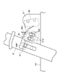
そして、上記ベース部材10におけるシフトレバー3の操作経路の前方に向かって左側の側方には、上記シフトピン21によって操作されるMレンジスイッチの操作機構が備えられている。
【0036】
この機構は、図5に拡大して示すように、シフトレバー3の上記側方におけるMレンジの選択位置の近傍においてベース部材10に立設された支持プレート31と、該支持プレート31のシフトレバー3側の面の上部にピン32を介して中央部が揺動自在に支持された操作レバー33と、上記ピン32に巻き付けられて両端が支持部材31と操作レバー33とにそれぞれ係止されていることにより、該操作レバー33を図5のA方向に付勢するツルマキバネ34とを有すると共に、上記支持プレート31における操作レバー33の後端部33aの下方にMレンジスイッチ35が取り付けられている。 なお、支持プレート31には、上記ツルマキバネ34による操作レバー33のA方向の揺動を所定位置で規制するためのストッパ部31aが設けられている。
【0037】
そして、操作レバー33の前端部33bが、シフトレバー3がMレンジに操作されたときに上記シフトピン21の左側の端部21aに係合し、該シフトピン21が上記ボタン3dの押し込み操作の解除により長穴3fに沿って上方へ移動するときに、該操作レバー33が上記ツルマキバネ34の付勢力に抗して反A方向に揺動され、後端部33aが上記Mレンジスイッチ35をON操作するようになっている。
【0038】
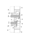
また、ベース部材10におけるシフトレバー3の操作経路の前方に向って右側の側方には、図6に拡大して示すように、その経路に沿ってガイドプレート41が該ベース部材10に一体的に立設され、このガイドプレート41と、シフトレバー3に備えられたシフトピン21とにより、前述のシフト操作規制機構が構成されている。
【0039】
上記ガイドプレート41は、シフトレバー3側の面の前部に設けられた厚肉部42を有し、この厚肉部42に、上記シフトピン21の右側の端部21bと係合することにより、シフトレバー3のPレンジ位置側からRレンジ位置側への操作を規制する第1規制面42aと、Rレンジ位置側からPレンジ位置側への移動を規制する第2規制面42bと、Nレンジ位置側からRレンジ位置側への移動を規制する第3規制面42cとが設けられて、シフトレバー3のこれらのレンジ間での操作を規制するようになっている。そして、上記ボタン3dの押し込み操作により、前述のスプリング24及び支持部材22を介してシフトピン21が下方に押し下げられたときに、この規制が解除されて、シフトレバー3の上記操作が許容されるようになっている。
【0040】
さらに、このガイドプレート41のシフトレバー3側の面には、前部に設けられた上記の厚肉部42に加えて、後部にも厚肉部43が設けられ、これらの厚肉部42,43の間が凹陥部44とされていると共に、この凹陥部44を利用して、Mレンジ内でのシフトレバー3に対する中立付勢機構と、シフトアップ、シフトダウンスイッチの操作機構とが設けられている。
【0041】
これらの機構は、上記凹陥部44内に配置された前後一対の第1,第2カム部材51,52を用いて構成されており、これらのカム部材51,52によってMレンジに操作されたシフトレバー3を中立位置に保持すると共に、該レバー3が中立位置から前後のシフトアップ位置またはシフトダウン位置に操作されたときには、いずれかのカム部材を介してシフトアップスイッチ53もしくはシフトダウンスイッチ54を操作するようになっている。
【0042】
上記一対のカム部材51,52のうち、後方に配置されたシフトダウン用の第2カム部材52の上端部にはガイドプレート41側に突出するピン部52aが一体的に設けられており、また、前方に配置されたシフトアップ用の第1カム部材51の上端部には穴51aが設けられて、上記第2カム部材52のピン部52aが第1カム部材51の穴51aに挿通された上で、ガイドプレート41に設けられた穴に嵌合されて抜け止めされており(図4参照)、これにより、両カム部材51,52が上端部における共通の支点を中心として、下部がそれぞれ前後に揺動可能に支持されている。また、第2カム部材52の上記ピン部52aにはツルマキバネ55が巻き付けられ、その両端部が両カム部材51,52に設けられた係止穴51b,52bにそれぞれ係止されて、これらのカム部材51,52が互いに接近する方向B,C、即ち第1カム部材51は後方、第2カム部材52は前方に付勢されている。
【0043】
そして、ガイドプレート41の凹陥部44内における両カム部材51,52に挟まれた位置には、シフトレバー3側へ突出する中央ストッパ部45が設けられて、該ストッパ部45の前後両面で、上記ツルマキバネ55の付勢力によるカム部材51,52の互いに接近する方向B,Cへの揺動を規制するようになっている。
【0044】
また、第1カム部材51の下端部には、肉盛りにより補強された下方への突出部51cが設けられ、シフトレバー3がDレンジ側からMレンジ側へ操作されたときに、シフトピン21が該突出部51cに当接すると共に、このカム部材51が上記中央ストッパ部45によって後方への揺動が規制されていることにより、シフトレバー3のMレンジ側への操作が阻止されるようになっている。
【0045】
そして、シフトピン21が押し下げられたときに、該シフトピン21と上記第1カム部材51の突出部51cとの当接が回避されて、シフトレバー3のMレンジ側への操作が許容されるようになっており、また、このMレンジ位置でシフトピン21の押し下げ操作を解除すれば、該シフトピン21は中央ストッパ部45により互いに接近する方向への揺動が規制された第1,第2カム部材51,52の間の間隙内に進入し、シフトピン21がこの間隙内に位置する状態が、シフトレバー3のMレンジ内における中立位置とされている。
【0046】
また、シフトレバー3がこの位置から前方に操作されると、シフトピン21を介して前側の第1カム部材51がツルマキバネ55に抗して前方(反B方向)へ揺動されると共に、該カム部材51は前方へ所定量揺動した位置で、ガイドプレート41の前側の厚肉部42の後面に設けられた前側ストッパ部42dに当接し、この位置でシフトレバー3のMレンジ内での前方への操作が規制されるようになっている。
【0047】
また、シフトレバー3が中立位置から後方に操作されると、シフトピン21を介して後側の第2カム部材52が同じくツルマキバネ55に抗して後方(反C方向)へ揺動されると共に、該カム部材52も後方へ所定量揺動した位置で、ガイドプレート41の後側の厚肉部43の前面に設けられた後側ストッパ部43dに当接し、この位置でシフトレバー3のMレンジ内での後方への操作が規制されるようになっている。そして、このシフトレバー3の前後の操作規制位置が、Mレンジ内でのシフトアップ位置及びシフトダウン位置とされている。
【0048】
さらに、図6及び図7に示すように、一対のカム部材51,52のガイドプレート41側の面には棒状のスイッチ操作部51d,52dがそれぞれガイドプレート41に直交する方向に突設され、その先端部がガイドプレート41に設けられた長穴46,47を貫通して該プレート41の背面側に突出している。そして、このガイドプレート41の背面に、シフトレバー3のシフトアップ位置及びシフトダウン位置への操作をそれぞれ検出する前述のシフトアップスイッチ53及びシフトダウンスイッチ54が前後に取り付けられており、シフトレバー3のシフトアップ位置への操作により第1カム部材51が前方へ揺動されたときには、該カム部材51のスイッチ操作部51dの先端がシフトアップスイッチ53の接片53aを押圧して該スイッチ53をONし、シフトレバー3のシフトダウン位置への操作により第2カム部材52が後方へ揺動されたときには、該カム部材52のスイッチ操作部52dの先端がシフトダウンスイッチ54の接片54aを押圧して、該スイッチ54をONするようになっている。
【0049】
ここで、この変速操作入力装置1の動作を説明する。
【0050】
シフトレバー3の上端の操作部3cに備えられた規制解除ボタン3dを押していないときは、該シフトレバー3の下部に設けられたシフトピン21は長穴3f,3fの上方に位置する。この状態では、図6に示すように、DレンジとNレンジとの間ではシフトピン21の移動が規制されないので、シフトレバー3をこれらのレンジ間で自由に操作することができるが、NレンジからRレンジへは、シフトピン21がガイドプレート41における厚肉部42の第3規制面42cに当接することによりシフトレバー3の操作が規制される。また、シフトレバー3がPレンジにあるときも、シフトピン21が上記ガイドプレート41の厚肉部42における第1規制面42aに当接してRレンジやDレンジ側への操作が規制される。
【0051】
また、規制解除ボタン3dを半ば押し込んだ状態では、シフトピン21が長穴3f,3fの中間位置まで押し下げられ、Nレンジ側からRレンジ側への操作が可能となるが、この状態ではシフトピン21が第2規制面42bに当接するので、RレンジからPレンジへの操作は規制される。そして、上記規制解除ボタン3dをさらに押し込んでシフトピン21を長穴3f,3fの下部まで移動させれば、RレンジからPレンジへの操作及びPレンジからRレンジ側への操作も可能となる。
【0052】
一方、シフトピン21が長穴3f,3fの上部に位置する状態では、Dレンジ側からMレンジ側へシフトレバー3を操作したときに、該シフトピン21が前側の第1カム部材51における下方への突出部51cに当接すると共に、このカム部材51はガイドプレート41に設けられた中央ストッパ部45に当接して後方への揺動が阻止されているから、シフトレバー3のMレンジ側への操作が阻止されることになる。これにより、Nレンジ等の前方に位置するレンジからDレンジへの操作時に、シフトレバー3が誤ってMレンジまで操作される、といった誤操作が防止されることになる。
【0053】
そして、Dレンジにおいて規制解除ボタン3dを押し込み操作してシフトピン21を押し下げると、該シフトピン21と上記突出部51cとの当接が回避されるので、シフトレバー3のMレンジ側への操作が可能となる。
【0054】
また、このMレンジの選択位置で上記ボタン3dの押し込み操作を解除すれば、シフトピン21がツルマキバネ55により互いに接近する方向に付勢されている第1,第2カム部材51,52の間の間隙に進入し、この位置で両カム部材51,52間に保持されることにより、シフトレバー3がMレンジの中立位置に保持されることになる。
【0055】
そして、このときシフトピン21の上方への移動により、図5に示すように、該ピン21の左側の端部21aがMレンジスイッチ操作機構における操作レバー33の前端部33bを押し上げる。これにより、該レバー33が反A方向に揺動して、その後端部33aがMレンジスイッチ35をON操作することになり、このスイッチ35からのON信号により、当該自動変速機のコントロールユニットがMレンジに操作されたことを検知する。
【0056】
つまり、シフトレバー3のMレンジへの操作後、規制解除ボタン3dの押し込み操作を解除することにより、Mレンジ内でのシフトレバー3の操作による手動変速が可能な状態となり、したがって、シフトレバー3のMレンジへの操作のみで変速が可能となる場合のような、運転者の意図しない変速が行われるといった不都合が防止され、当該変速操作入力装置1ないし変速機としての信頼性が確保される。
【0057】
さらに、このMレンジの選択位置でシフトレバー3を上記の中立位置から前方のシフトアップ位置に操作すれば、前側の第1カム部材51が前方へ揺動して、該カム部材51の操作部51dがガイドプレート41の背面の前側に配置されたシフトアップスイッチ53をON操作し、逆に後方のシフトダウン位置に操作すれば、後側の第2カム部材52が後方へ揺動して、該カム部材52の操作部52dが同じくガイドプレート41の背面の後側に配置されたシフトダウンスイッチ54をON操作する。そして、これらのスイッチ53,54からの信号が上記コントロールユニットに入力されることにより、該コントロールユニットは変速段を1段、シフトアップまたはシフトダウンするように変速指令を出力する。
【0058】
ところで、この変速操作入力装置1によれば、シフトレバー3の揺動操作面に平行に立設されたガイドプレート41の該シフトレバー3側の面に、該シフトレバー3の揺動面と平行な面上で揺動する一対のカム部材51,52を配置すると共に、このガイドプレート41の背面側にシフトアップスイッチ53とシフトダウンスイッチ54とを配置した構成であるから、シフトレバー3とこれらのスイッチ53,54との干渉が回避され、しかも、ガイドプレート41の両面を有効利用することにより当該スイッチ操作機構の大型化が抑制されることになる。
【0059】
また、一対のカム部材51,52はガイドプレート41における前後の厚肉部42,43の間の凹陥部44に収納された状態で支持されているから、ガイドプレート41の厚さや強度を確保しながら、カム部材51,52を含む中立付勢機構全体の幅方向の寸法を抑制することができ、当該装置1の幅方向寸法も短縮されることになる。
【0060】
そして、本来シフトピン21と協働してシフトレバー3の所定のレンジ間の操作を規制するためのガイドプレート41に上記カム部材51,52を支持させると共に、該ガイドプレート41の前側の厚肉部42の後面及び後側の厚肉部43の前面を利用して、一対のカム部材51,52の前方及び後方への揺動をそれぞれ所定範囲で規制するストッパ部42d,43dを構成したので、上記カム部材51,52の支持やその揺動の規制等をそれぞれ別部材によって行う場合より部品点数が少なくなると共に、構造が簡素化されることになり、また、このガイドプレート41自体が合成樹脂製のベース部材10に一体的に成形されているので、この点でも部品点数が少なくなる。
【0061】
さらに、一対のカム部材51,52によりシフトレバー3をMレンジ内の中立位置に付勢する際に、所定のレンジ間での操作を規制するためのシフトピン21を利用して付勢するようにしたから、カム部材51,52による中立位置への付勢力をシフトレバー3に伝達する部材と、該シフトレバー3の操作を規制する部材とが兼用されることになる。また、上記のように、シフトレバー3を中立位置に付勢する一対のカム部材51,52により、シフトアップスイッチ53及びシフトダウンスイッチ54をそれぞれ操作するようにしたので、Mレンジ内でのシフトレバー3の操作に連動して上記スイッチ53,54を操作するための部材を別途設ける必要がなく、しかも、一対のカム部材51,52は1本のツルマキバネ55によりシフトレバー3の中立位置方向へ付勢されるようになっており、これらの点でも部品点数が削減されて、当該変速操作入力装置1がきわめて簡素に構成されることになる。
【0062】
また、上記シフトピン21はシフトレバー3の左右両側に突出し、Mレンジにおいては、一方の端部21aでMレンジスイッチ35をON操作すると共に、他方の端部21bで中立付勢用のカム部材51,52を介してシフトアップスイッチ53及びシフトダウンスイッチ54を操作するようになっているから、該シフトピン21には両端部に荷重が作用することになる。これにより、一端側にのみ荷重が作用する場合のシフトピン21のこじれ等が防止され、該シフトピン21の耐久性が向上して、良好な操作性が長期にわたって維持されることになる。
【0063】
なお、図8は、Mレンジスイッチ操作機構の他の構成例を示すもので、この例では、ベース部材10′に立設される支持プレート31′が該ベース部材10′に一体的に成形されていると共に、この支持プレート31′の前部に2つの長穴31a′,31a′が設けられ、これらの長穴31a′,31a′に操作部材33′に設けられた2つの突起33a′,33a′がそれぞれ係合されて、該操作部材33′が上下にスライド可能に支持されている。
【0064】
そして、この操作部材33′の前方に延びる係合部33b′が、Mレンジに操作されたシフトレバー3′におけるシフトピン21′の端部に係合され、該シフトピン21′が上方へ移動したときに、操作部材33′も自重に抗して上方へスライドされ、このとき、該操作部材33′により支持プレート31′の後部に取り付けられたMレンジスイッチ35′の接片35a′がON操作されるようになっている。
【0065】
したがって、この操作機構によっても、図5に示すものと同様に、Mレンジスイッチ35′が操作されることになる。
【0066】
次に、前述のカバー2及び該カバー2の開口部2aを閉鎖するスライドプレート5の構造、及びこれらを用いたレンジ選択位置表示機構について説明する。
【0067】
図3、図4に示すように、カバー2は上部カバー61と下部カバー62とで中空状に構成され、上部カバー61における開口部2aの一側方に前述の操作位置表示板4が取り付けられていると共に、その下方には該表示板4を下方から照明するランプ63が備えられている。そして、開口部2aの左右両側部に沿って上下のカバー61,62間に隙間が設けられ、この隙間にスライドプレート5の左右両側部が係合されていると共に、該プレート5の中央に設けられた穴5aにシフトレバー3のパイプ部材3aが挿通され、該シフトレバー3の操作によりスライドプレート5が前後にスライドするようになっている。
【0068】
一方、図9に示すように、上記操作位置表示板4には、シフトレバー3の各レンジ選択位置に応じて「P」、「R」、「N」、「D」、「M」の文字が付されていると共に、これらの文字の開口部2a側の側方には表示窓4p,4r,4n,4d,4mがそれぞれ設けられている。これらの表示窓のうち、「P」〜「D」の文字の側方に設けられた表示窓4p〜4dは前後一列に配列されているのに対し、「M」の側方に設けられた表示窓4mは、上記列に対して開口部2a側にオフセットされた位置に設けられている。
【0069】
また、スライドプレート5における操作位置表示板4側の側部には、前後方向の長さが長い第1段目の突出部5bと、該突出部5bからさらに当該側方へ突出する前後方向の長さが短い第2段目の突出部5cとが設けられて、これらの突出部5b,5cが例えば赤色等に着色されている。そして、第1段目の突出部5bが、左右方向の位置で、操作位置表示板4における「M」の文字の側方の表示窓4mの位置に対応し、第2段目の突出部5cが、「P」〜「D」の文字の側方に設けられた表示窓4p〜4dの列に対応位置するようになっている。
【0070】
したがって、図10に示すように、シフトレバー3がMレンジに操作されているときには、そのレンジ内で該シフトレバー3がシフトアップまたはシフトダウン操作として前後に操作されても、Mレンジ用の第1段目の突出部5bは前後方向に長いので、常に着色部が当該表示窓4mの全体に表示されることになると共に、Mレンジ以外では、この第1段目の突出部5bは、他のレンジの表示窓4p〜4dの列に対してオフセットされているから、これらの表示窓4p〜4dに現れることはない。
【0071】
そして、符号イで示すように、シフトレバー3がMレンジ以外のレンジに操作されているときに、これらのレンジの表示窓4p〜4dのいずれかに、第2段目の突出部5cが現れることになるが、この第2段目の突出部は前後方向の寸法が短いので、各窓4p〜4dの間隔が狭くても、複数の表示窓に同時に着色部が現れることがない。
【0072】
これにより、Mレンジ及びMレンジ以外の他のレンジのいずれにおいても、操作位置表示板4における各表示窓4p〜4mのうちのシフトレバー3によって選択されているレンジの表示窓に、着色部が良好に表示されることになる。
【0073】
なお、図11に示すレンジ選択位置表示機構においては、カバー2′における操作位置表示板4′に、図9、図10に示す表示板4と同様に、シフトレバー3′の各レンジ選択位置に応じて「P」、「R」、「N」、「D」、「M」の文字が付されていると共に、これらの文字の開口部2a′側の側方に表示窓4p′,4r′,4n′,4d′,4m′がそれぞれ設けられているが、これらの表示窓のうち、「P」〜「D」の文字の側方に設けられた表示窓4p′〜4d′の列に対して、「M」の側方に設けられた表示窓4m′が開口部2aと反対側にオフセットされている。
【0074】
また、スライドプレート5′における操作位置表示板4′側の側部には、その側辺に沿って前後方向の長さが短い第1段の突出部5b′が、また、その外側に前後方向の長さが長い第2段の突出部5c′が設けられて、これらの突出部5b′,5c′が全体形状として、T字状をなしている。
【0075】
この例においても、操作位置表示板4′におけるMレンジ用の表示窓4m′に前後方向の長さが長い突出部5c′が、Mレンジ以外のレンジ用の表示窓4p′〜4d′に前後方向の長さが短い突出部5b′がそれぞれ対応することになるから、図9、図10に示す表示機構と同様の作用が得られる。
【0076】
【発明の効果】
以上のように、本発明によれば、変速段を手動によるシフトレバーの揺動操作によって切り換えるMレンジを有すると共に、このMレンジを含む複数のレンジのシフトレバーの揺動操作による選択位置が一列に配置され、かつ、Mレンジ内での上記操作が上記列の方向に沿って行われるように構成された自動変速機において、シフトレバーのカバー部材に該シフトレバーの選択位置を表示するレンジごとの表示窓が設けられる場合に、Mレンジ内でシフトレバーのシフトアップまたはシフトダウンの操作を行っても、Mレンジ用表示窓は、常にその全体が一様に所定の表示状態に維持されると共に、Mレンジ以外の他のレンジでは、当該他のレンジ用の表示窓のみに選択表示が行われて、他の表示窓の一部に選択表示が現れるといったことが防止される。
【0077】
これにより、カバー部材における各表示窓間の間隔を長くして、シフトレバーの操作性を悪化させたり、当該変速操作入力装置の前後方向寸法を増大させたりする等の種々の不都合を招くことなく、Mレンジ及びその他のレンジについての選択表示が良好に行われるようになる。
【0078】
なお、第2発明によれば、上記効果が、複数のレンジとして、P、R、N、D、Mの各レンジを有し、これらのレンジの選択位置がシフトレバーの操作方向に沿って一列に配置された自動変速機において得られることになる。
【0079】
また、第3発明によれば、スライドプレートの一側部に二段に設けられる表示用突出部の全体形状が、基端部が太く、先端部が細い安定した形状となるので、変形や折損等のおそれが少なくなり、耐久性が向上する。
【図面の簡単な説明】
【図1】本発明の実施の形態に係る変速操作入力装置におけるシフトレバー及びその周辺の外観図である。
【図2】同装置の平面図である。
【図3】同じく側面図である。
【図4】図3のa−a線による断面図である。
【図5】Mレンジスイッチ操作機構の拡大側面図である。
【図6】図2のb−b線に沿ってみたガイドプレート及びその周辺の拡大側面図である。
【図7】図6のc−c線に沿う断面図である。
【図8】Mレンジスイッチ操作機構の他の実施の形態を示す側面図である。
【図9】スライドプレートを用いたレンジ選択位置表示機構を示す平面図である。
【図10】同機構の作用を示す平面図である。
【図11】同機構の他の実施の形態を示す平面図である。
【図12】同機構の従来の問題点を示す平面図である。
【符号の説明】
1 変速操作入力装置
2,2′ カバー部材
3,3′ シフトレバー
4p〜4m、4p′〜4m′ 表示窓
5,5′ スライドプレート
5b,5c′ Mレンジ用突出部
5b′,5c 他のレンジ用の突出部[0001]
BACKGROUND OF THE INVENTION
The present invention relates to an automatic transmission, in particular, a shift of an automatic transmission having a manual range (hereinafter referred to as an M range) for switching a shift stage by a swinging operation of a shift lever in addition to a D range for automatically switching a shift stage. The present invention relates to an operation input device.
[0002]
[Prior art]
2. Description of the Related Art In recent years, automatic transmissions for vehicles have been put into practical use with an M range that switches gears by manual operation in addition to a D range that automatically switches gears. For example, there is one disclosed in JP-A-4-244655.
[0003]
In this automatic transmission, P (parking), R (reverse), N (neutral), D (drive), 3 (third speed) are operated by swinging the shift lever in the first shift gate in the longitudinal direction of the vehicle body. 2) (2nd speed), 1 (1st speed) range can be selected, and parallel to the first shift gate for the M range through a gate extending laterally from the selected position of the D range. A second shift gate is provided. In the second shift gate, the shift lever is urged to the neutral position, and when operated forward from the neutral position, the shift stage is shifted up by one stage, and when operated backward, the shift stage is shifted down by one stage. It is configured as follows.
[0004]
By the way, when the second shift gate for M range is provided beside the first shift gate for normal range selection as described above, the overall shape of the shift gate or the width of the operation region of the shift lever is wide. As a result, the overall size of the speed change operation device also increases in the lateral direction. For this reason, the mounting on the vehicle body is hindered, and the layout with peripheral devices becomes difficult.
[0005]
In response to this, the M range selection position is arranged at one end of the row of the selection positions of the ranges arranged in the longitudinal direction of the vehicle body, and the M range is selected when the shift lever is operated to the end of the row. At the same time, it is conceivable that the gear position is shifted up or down by operating the shift lever in the front-rear direction within the selected position of the M range. According to this, the shift lever only moves linearly in the front-rear direction, the width of the operation area of the shift lever is narrowed, and accordingly, the lateral dimension of the speed change operating device is also suppressed. Become.
[0006]
On the other hand, in this type of shift operation input device for an automatic transmission, a display mechanism that indicates the current selection range is provided on the side of the operation line of the shift lever, and this mechanism is generally configured as follows.
[0007]
That is, as shown in FIG. 12, the shift lever A is swung in the longitudinal direction of the vehicle body in the opening B1 of the cover member B fixed to the vehicle body side, and the opening B1 is attached to the shift lever A. In the configuration closed by the slide plate C that is slidable in the operation direction of the lever A below the cover member B, a projection C1 for displaying the selected position is provided on one side of the slide plate C. The cover member B is provided with the same number of display windows Bp, Br, Bn, Bd, Bm as the number of ranges for exposing the protrusion C1 of the slide plate C. It is provided and characters indicating the range are attached to the display windows Bp to Bm. As shown in the figure, for example, when the shift lever A is operated to the M range, the projecting portion C1 of the slide plate C is located below the display window Bm for the M range in the cover member B, and this The display window Bm for the M range is configured to display a color different from that of the other display windows Bp to Bd.
[0008]
[Problems to be solved by the invention]
By the way, the selected range display mechanism as described above is arranged in a row with a plurality of range selection positions including the automatic transmission in the range selection position serial arrangement as described above, that is, the M range by the swing operation of the shift lever. In addition, when the present invention is applied to an automatic transmission that is configured such that the swinging operation of the shift lever within the M range is performed along the direction of the row, the following problems may occur.
[0009]
That is, as shown in FIG. 12, in the M range, the shift lever A is operated in the front-rear direction within a certain range x in order to shift up or down the gear position. In order to always display the color of the projecting portion C1 of the slide plate C over the entire window Bm, the size of the projecting portion C1 in the front-rear direction must be sufficiently long.
[0010]
However, if this is done, as shown by the chain line A in FIG. A, for example, when the shift lever A is operated to the N range, the N range display window Bn and the adjacent display windows Br and Bd The dimension in the front-rear direction of the projecting portion C1 of the slide plate C becomes too large with respect to the interval, and the color of the projecting portion C1 is exposed in a part of the adjacent display windows Br and Bd, which deteriorates the appearance. . In order to prevent this, if the length in the front-rear direction of the protrusion C1 is shortened, a portion where the protrusion C1 is colored is present in a part of the display window Bm for M range during operation in the M range. In this case, the appearance is also deteriorated.
[0011]
For this, the length in the front-rear direction of the protruding portion of the slide plate may be increased and the interval between the display windows in the cover member may be sufficiently increased. In this case, for example, the N range and the D adjacent thereto are used. The stroke of the shift lever between the range and the R range becomes longer, which causes various inconveniences such as deterioration in operability and increase in the longitudinal dimension of the speed change operation input device.
[0012]
The speed change operation input device according to the present invention deals with the above-described situation in the automatic transmission having the M range, which causes deterioration in operability, an increase in the longitudinal dimension of the speed change operation input device, and the like. It is an object of the present invention to make it possible to satisfactorily perform selection display for the M range and other ranges.
[0013]
[Means for Solving the Problems]
In order to solve the above problems, the present invention uses the following means.
[0014]
First, the invention described in
[0015]
The invention described in claim 2 (hereinafter referred to as the second invention) in the first invention shifts the selection positions of the ranges of P, R, N, D, and M as the selection positions of the plurality of ranges. Arranged in a line along the lever operating direction, and the display windows of the cover member are aligned in a row for the P, R, N, and D ranges, and the one for the M range is offset with respect to these. It is provided.
[0016]
Further, the invention described in claim 3 (hereinafter referred to as the third invention) is the same as that of the first invention. In addition to being offset closer to the operation line, the display protrusion on the side of the slide plate is also provided with an M range protrusion closer to the operation line of the shift lever.
[0017]
By using the above-mentioned means, each invention of the present application operates as follows.
[0018]
First, according to any of the first to third inventions, the display window for the M range and the other display window for the range in the cover member are offset in a direction orthogonal to the operation direction of the shift lever, and this offset Correspondingly, the projection for M range of the slide plate and the projection for other range are provided in a state of projecting in two steps on the side of the slide plate. In the M range, except for being displayed on the display window for the M range, it is not displayed on other display windows. Since the M range projection has a long dimension in the shift lever operation direction, the M range projection is always used for the M range even if the shift lever is shifted up or down in the M range. The state displayed on the entire display window is maintained.
[0019]
In addition, since the protruding portion for the other range other than the M range on the slide plate has a short dimension in the shift lever operation direction, it protrudes to a display window other than the other range display window in a range other than the M range. The part is prevented from being exposed.
[0020]
And according to 2nd invention, the effect | action of said 1st invention has each range of P, R, N, D, and M as a plurality of ranges, and the selection position of these ranges is the operation direction of a shift lever. In an automatic transmission arranged in a line along
[0021]
Further, according to the third invention, the display window for the M range in the cover member is offset closer to the operation line of the shift lever with respect to the display window for the other ranges, and correspondingly, The display protrusion on the side of the slide plate that protrudes in two steps is also provided with the M-range protrusion that has a long dimension in the shift lever operation direction closer to the operation line of the shift lever. Protruding part with a long dimension in the direction along the side is provided on the part, and further, a protruding part with a short dimension in the same direction is provided on the outer side. It is thick and has a stable shape with a thin tip.
[0022]
DETAILED DESCRIPTION OF THE INVENTION
Embodiments of the present invention are described below.
[0023]
FIG. 1 shows an appearance of a speed change
[0024]
The
[0025]
The
[0026]
Next, the structure of the portion of the speed change
[0027]
A hollow box-like projecting
[0028]
On the
[0029]
The positioning mechanism includes a
[0030]
Further, the
[0031]
The
[0032]
On the other hand, the
[0033]
The mounting structure of the
[0034]
The
[0035]
An operation mechanism for an M range switch operated by the
[0036]
As shown in an enlarged view in FIG. 5, this mechanism includes a
[0037]
The
[0038]
Further, on the right side of the operation path of the
[0039]
The
[0040]
Further, in addition to the above-described
[0041]
These mechanisms are configured using a pair of front and rear first and
[0042]
Of the pair of
[0043]
A
[0044]
Further, the lower end portion of the
[0045]
When the
[0046]
When the
[0047]
When the
[0048]
Further, as shown in FIGS. 6 and 7, rod-like
[0049]
Here, the operation of the shift
[0050]
When the
[0051]
In the state where the
[0052]
On the other hand, in a state where the
[0053]
When the
[0054]
Further, if the pushing operation of the
[0055]
At this time, due to the upward movement of the
[0056]
That is, after the
[0057]
Further, when the
[0058]
By the way, according to this shift
[0059]
Further, since the pair of
[0060]
Then, the
[0061]
Further, when the
[0062]
The
[0063]
FIG. 8 shows another configuration example of the M range switch operating mechanism. In this example, a
[0064]
When the engaging
[0065]
Therefore, also by this operation mechanism, the M range switch 35 'is operated as in the case shown in FIG.
[0066]
Next, the structure of the
[0067]
As shown in FIGS. 3 and 4, the
[0068]
On the other hand, as shown in FIG. 9, characters “P”, “R”, “N”, “D”, and “M” are displayed on the operation
[0069]
Further, on the side of the
[0070]
Therefore, as shown in FIG. 10, when the
[0071]
Then, as indicated by reference symbol (a), when the
[0072]
Thereby, in any range other than the M range and the M range, the colored portion is formed on the display window of the range selected by the
[0073]
In the range selection position display mechanism shown in FIG. 11, the operation
[0074]
Further, on the side of the slide plate 5 'on the side of the operation position display plate 4', there is a first-
[0075]
Also in this example, the
[0076]
【The invention's effect】
As described above, according to the present invention, the M range is selected by manually shifting the shift stage by the swinging operation of the shift lever, and the selection positions by the swinging operation of the shift levers of a plurality of ranges including the M range are aligned. And an automatic transmission configured so that the operation in the M range is performed along the direction of the row, for each range in which the shift lever cover member displays the selected position of the shift lever. When the display window is provided, even if the shift lever is shifted up or down within the M range, the entire M range display window is always maintained in a predetermined display state. At the same time, in other ranges other than the M range, the selection display is performed only on the display window for the other range, and the selection display appears in a part of the other display window. It is locked.
[0077]
Thereby, the space | interval between each display window in a cover member is lengthened, without causing the various inconveniences, such as deteriorating the operativity of a shift lever and increasing the front-back direction dimension of the said shift operation input device. , The selection display for the M range and other ranges is performed well.
[0078]
According to the second invention, the above effect has a plurality of ranges of P, R, N, D, and M, and the selection positions of these ranges are aligned along the operation direction of the shift lever. It is obtained in an automatic transmission arranged in
[0079]
In addition, according to the third aspect of the invention, the overall shape of the display protrusion provided in two steps on one side of the slide plate is a stable shape with a thick base end and a thin tip. Etc., and the durability is improved.
[Brief description of the drawings]
FIG. 1 is an external view of a shift lever and its surroundings in a shift operation input device according to an embodiment of the present invention.
FIG. 2 is a plan view of the apparatus.
FIG. 3 is a side view of the same.
4 is a cross-sectional view taken along line aa in FIG.
FIG. 5 is an enlarged side view of an M range switch operating mechanism.
6 is an enlarged side view of the guide plate and its periphery as viewed along the line bb in FIG. 2;
7 is a cross-sectional view taken along the line cc of FIG.
FIG. 8 is a side view showing another embodiment of the M range switch operating mechanism.
FIG. 9 is a plan view showing a range selection position display mechanism using a slide plate.
FIG. 10 is a plan view showing the operation of the mechanism.
FIG. 11 is a plan view showing another embodiment of the mechanism.
FIG. 12 is a plan view showing a conventional problem of the mechanism.
[Explanation of symbols]
1 Shifting operation input device
2,2 'cover member
3, 3 'shift lever
4p-4m, 4p'-4m 'display window
5,5 'slide plate
5b, 5c 'Protrusion for M range
5b ', 5c Protrusion for other ranges
Claims (3)
Priority Applications (1)
| Application Number | Priority Date | Filing Date | Title |
|---|---|---|---|
| JP28001796A JP3614583B2 (en) | 1996-09-30 | 1996-09-30 | Shifting operation input device for automatic transmission |
Applications Claiming Priority (1)
| Application Number | Priority Date | Filing Date | Title |
|---|---|---|---|
| JP28001796A JP3614583B2 (en) | 1996-09-30 | 1996-09-30 | Shifting operation input device for automatic transmission |
Publications (2)
| Publication Number | Publication Date |
|---|---|
| JPH10100724A JPH10100724A (en) | 1998-04-21 |
| JP3614583B2 true JP3614583B2 (en) | 2005-01-26 |
Family
ID=17619148
Family Applications (1)
| Application Number | Title | Priority Date | Filing Date |
|---|---|---|---|
| JP28001796A Expired - Fee Related JP3614583B2 (en) | 1996-09-30 | 1996-09-30 | Shifting operation input device for automatic transmission |
Country Status (1)
| Country | Link |
|---|---|
| JP (1) | JP3614583B2 (en) |
-
1996
- 1996-09-30 JP JP28001796A patent/JP3614583B2/en not_active Expired - Fee Related
Also Published As
| Publication number | Publication date |
|---|---|
| JPH10100724A (en) | 1998-04-21 |
Similar Documents
| Publication | Publication Date | Title |
|---|---|---|
| JP3725634B2 (en) | Shifting operation input device for automatic transmission | |
| US7966905B2 (en) | Shift apparatus | |
| US20050223834A1 (en) | Inline automatic/manual shifter | |
| JP3614583B2 (en) | Shifting operation input device for automatic transmission | |
| JP3592859B2 (en) | Shift operation input device for automatic transmission | |
| JP3592858B2 (en) | Shift operation input device for automatic transmission | |
| JP3705315B2 (en) | Shifting operation input device for automatic transmission | |
| JP3592857B2 (en) | Shift operation input device for automatic transmission | |
| JP3636841B2 (en) | Shifting operation input device for automatic transmission | |
| JP3636840B2 (en) | Shifting operation input device for automatic transmission | |
| JP3725664B2 (en) | Shifting operation input device for automatic transmission | |
| JP3636842B2 (en) | Shifting operation input device for automatic transmission | |
| JP3724081B2 (en) | Automatic transmission control device | |
| JPH10100720A (en) | Shift operation input device of automatic transmission | |
| JP3397701B2 (en) | Shift lever device | |
| JP4036979B2 (en) | Shift lock structure of automatic transmission | |
| JP3751718B2 (en) | Shifting operation input device for automatic transmission | |
| JP3768651B2 (en) | Shifting operation input device for automatic transmission | |
| JP3799686B2 (en) | Control device for automatic transmission | |
| JP3751717B2 (en) | Shifting operation input device for automatic transmission | |
| JP2876089B2 (en) | Shift device with manual speed selection mechanism for automatic transmission for vehicles | |
| JP3742187B2 (en) | Shifting operation input device for automatic transmission | |
| US10871220B2 (en) | Shifter mechanism with manual shift function | |
| JPH106799A (en) | Shift unit of automatic transmission for automobile | |
| JPH10100722A (en) | Control device for automatic transmission |
Legal Events
| Date | Code | Title | Description |
|---|---|---|---|
| A977 | Report on retrieval |
Free format text: JAPANESE INTERMEDIATE CODE: A971007 Effective date: 20040930 |
|
| TRDD | Decision of grant or rejection written | ||
| A01 | Written decision to grant a patent or to grant a registration (utility model) |
Free format text: JAPANESE INTERMEDIATE CODE: A01 Effective date: 20041026 |
|
| A61 | First payment of annual fees (during grant procedure) |
Free format text: JAPANESE INTERMEDIATE CODE: A61 Effective date: 20041027 |
|
| R150 | Certificate of patent or registration of utility model |
Free format text: JAPANESE INTERMEDIATE CODE: R150 |
|
| FPAY | Renewal fee payment (event date is renewal date of database) |
Free format text: PAYMENT UNTIL: 20071112 Year of fee payment: 3 |
|
| FPAY | Renewal fee payment (event date is renewal date of database) |
Free format text: PAYMENT UNTIL: 20081112 Year of fee payment: 4 |
|
| LAPS | Cancellation because of no payment of annual fees |