JP3613195B2 - Alloy hot-dip galvanized steel sheet - Google Patents
Alloy hot-dip galvanized steel sheet Download PDFInfo
- Publication number
- JP3613195B2 JP3613195B2 JP2001114628A JP2001114628A JP3613195B2 JP 3613195 B2 JP3613195 B2 JP 3613195B2 JP 2001114628 A JP2001114628 A JP 2001114628A JP 2001114628 A JP2001114628 A JP 2001114628A JP 3613195 B2 JP3613195 B2 JP 3613195B2
- Authority
- JP
- Japan
- Prior art keywords
- steel sheet
- network structure
- plating
- less
- dip galvanized
- Prior art date
- Legal status (The legal status is an assumption and is not a legal conclusion. Google has not performed a legal analysis and makes no representation as to the accuracy of the status listed.)
- Expired - Fee Related
Links
- 0 CCCC(C)(C1(C2)CC(C)C3C4(C5C6)C56C3C(*3C5(C)C3)C(C)(C)C(C)(C)C)[C@@]3(C)C14C25C3(C)C(*)=C Chemical compound CCCC(C)(C1(C2)CC(C)C3C4(C5C6)C56C3C(*3C5(C)C3)C(C)(C)C(C)(C)C)[C@@]3(C)C14C25C3(C)C(*)=C 0.000 description 3
Images


Landscapes
- Coating With Molten Metal (AREA)
Description
【0001】
【発明の属する技術分野】
この発明は、プレス成形における摺動性に優れた合金化溶融亜鉛めっき鋼板に関するものである。
【0002】
【従来の技術】
合金化溶融亜鉛めっき鋼板は、亜鉛めっき鋼板と比較して塗装性及び溶接性に優れることから、自動車や家電製品等に広く利用されている。
【0003】
このような合金化溶融亜鉛めっき鋼板は、プレス成形を施されて目的の用途に供される。しかし、合金化溶融亜鉛めっき鋼板は、冷延鋼板に比べてプレス成形性が劣るという欠点を有する。これは合金化溶融亜鉛めっき鋼板とプレス金型との摺動抵抗が、冷延鋼板の場合に比較して大きいことが原因である。即ち、ビードと亜鉛系めっき鋼板との摺動抵抗が著しく大きい部分で、合金化溶融亜鉛めっき鋼板がプレス金型に流入しにくくなり、鋼板の破断が起こりやすい。
【0004】
そこで亜鉛系めっき鋼板のプレス成形性を向上させる方法としては、一般に高粘度の潤滑油を塗布する方法が広く用いられている。しかしこの方法では、潤滑油の高粘性のために、塗装工程で脱脂不良による塗装欠陥が発生したり、またプレス時の油切れにより、プレス性能が不安定になる等の問題がある。前記問題を解決するには、潤滑油の塗布量を極力低減できることが必要であり、そのためには、合金化溶融亜鉛めっき鋼板自体のプレス成形性を改善することが必要となる。
【0005】
合金化溶融亜鉛めっき鋼板は、鋼板に亜鉛めっきを施した後、加熱処理を行い、鋼板中のFeとめっき層中のZnが拡散する合金化反応が生じることにより、Fe−Zn合金相を形成させたものである。このFe−Zn合金相は、通常、Γ相、δ1相、ζ相からなる皮膜であり、Fe濃度が低くなるに従い、すなわち、Γ相→δ1相→ζ相の順で、硬度ならびに融点が低下する傾向がある。このため、摺動性の観点からは、高硬度で、融点が高く凝着の起こりにくい高Fe濃度の皮膜が有効であり、プレス成形性を重視する合金化溶融亜鉛めっき鋼板は、皮膜中の平均Fe濃度を高めに製造されている。
【0006】
しかしながら、高Fe濃度の皮膜では、めっき−鋼板界面に硬くて脆いΓ相が形成されやすく加工時に、界面から剥離する現象、いわゆるパウダリングが生じ易い問題を有している。このため、特開平1−319661号公報に示されているように、摺動性と耐パウダリング性を両立するために、上層に第二層として硬質のFe系合金を電気めっきなどの手法により付与する方法がとられている。
【0007】
めっき皮膜を二層とすることは製造コストが余計にかかるという問題も有している。この問題を解決する方法として、特開昭53−60332号公報および特開平2−190483号公報は、亜鉛系めっき鋼板の表面に電解処理、浸漬処理、塗布酸化処理、または加熱処理を施すことにより、ZnOを主体とする酸化膜を形成させて溶接性、または加工性を向上させる技術を開示している。
【0008】
特開平4−88196号公報は、亜鉛系めっき鋼板の表面に、リン酸ナトリウム5〜60g/lを含みpH2〜6の水溶液中にめっき鋼板を浸漬するか、電解処理、また、上記水溶液を散布することによりP酸化物を主体とした酸化膜を形成して、プレス成形性及び化成処理性を向上させる技術を開示している。
【0009】
特開平3−191093号公報は、亜鉛系めっき鋼板の表面に電解処理、浸漬処理、塗布処理、塗布酸化処理、または加熱処理により、Ni酸化物を生成させることによりプレス成形性および化成処理性を向上させる技術を開示している。
【0010】
特開平7−18402号公報は、合金化溶融亜鉛めっき鋼板の表面に凹部を形成させることで、潤滑油を鋼板表面に保持しやすくし、プレス成形性を向上させる技術を開示している。
【0011】
【発明が解決しようとする課題】
しかしながら、上述した先行技術を合金化溶融亜鉛めっき鋼板に適用した場合、プレス成形性の改善効果を安定して得ることはできない。発明者らは、この原因について詳細な検討を行った。その結果、合金化溶融めっき鋼板はAl酸化物が不均一に存在することにより表面の反応性が不均一であること、及びめっき表面の粗さが大きいことが原因であることを見出した。即ち、上述した先行技術を合金化溶融めっき鋼板に適用した場合、表面の反応性が不均一であるため、電解処理、浸漬処理、塗布酸化処理及び加熱処理等を行っても所定の皮膜を表面に均一に形成することは困難であり、反応性の低い(Al酸化物量が多い)部分では膜厚が薄くなってしまう。また、めっき表面は合金化反応の不均一性およびFe−Zn合金相の形状により数ミクロン以上のマクロな凹凸が大きい。プレス成型時にプレス金型と直接接触するのは表面の凸部となるが、凸部のうち膜厚の薄い部分と金型との接触部での摺動抵抗が大きくなり、プレス成形性の改善効果が十分には得られない。
【0012】
また、凹部を形成させる技術についても、これだけでは十分なプレス成形性が得られないことがわかった。これは、凹部には潤滑油が溜まり易いが、逆に摺動性に与える影響が大きい凸部には潤滑油が溜まりにくいという問題があるためと考えられる。
【0013】
この発明は上記の問題点を解決するためになされたもので、プレス成形における摺動性に優れた合金化溶融めっき鋼板を提供することを目的とする。
【0014】
【課題を解決するための手段】
本発明者らは、上述した目的を達成すべく、鋭意研究を重ねた結果、合金化溶融亜鉛めっき鋼板のめっき表面に平坦部を設け、その平坦部に微細な凹凸を形成することで、高度に安定して優れたプレス成形性が得られることを知見した。本発明における粗さは先行文献に示されているめっき表面の粗さとはそのスケールにおいてまったく異質のものである。すなわち、先行文献(例えば特許第2704070号公報)ではめっき表面全体を対象としたマクロ粗さであり(例えば、数10mm×数10mmの範囲内の粗さ、Ra≧1μm)、本発明ではめっき表面上に形成された平坦部(典型的には数μm×数μm)内の微細凹凸(Ra≦10nm)を問題としている。
【0015】
次に本発明を具体的に述べる。合金化溶融亜鉛めっき鋼板は、合金化処理時の鋼板−めっき界面の反応性の差およびFe−Zn合金の角張った形状により、めっき表面にマクロな粗さが存在している。このような合金化溶融亜鉛めっき鋼板に平坦部を設ける。平坦部を設けることによって、めっき表面の凹凸を緩和し表面を平滑にすると同時にめっき表面の凸部を平坦にする。平坦部の形成方法は特に限定されないが、調質圧延と兼ねてもよい。このようにして形成された合金化溶融亜鉛めっき鋼板表面の平坦部は、プレス成形時に金型が直接接触する部分であるため、この平坦部の摺動抵抗を小さくすることが、プレス成形性を安定して改善することにつながるのである。
【0016】
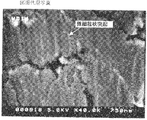
図1は、このような合金化溶融亜鉛めっき鋼板表面の二次電子像である。図中で暗く見えるところが平坦部である。発明者らは平坦部の表面に微細な凹凸を形成させることにより鋼板の摺動抵抗が減少することを知見した。さらに、微細な凹凸の粗さパラメータと摩擦係数との関係を一つの指標として種々の微細凹凸について系統的な研究を行った結果、大きさや形状を制御して平坦部に微細凹凸を付与することが摺動抵抗の減少につながることを知見した。さらに、微細な凹凸のすべてあるいは一部をめっき皮膜のFe−Zn合金よりも高融点の物質、例えばZn主体の酸化物、で構成させることによりさらに優れた摺動抵抗低減効果が得られることがわかった。
【0017】
本発明は、以上の知見に基づいてなされたものである。
【0018】
第1発明は、Fe−Zn合金めっき相を少なくとも鋼板の片面に有し、かつ、めっき面に調質圧延によって平坦にされた平坦部を有するとともに、前記平坦部表面に、凸部と、前記凸部により囲まれる不連続な凹部で構成される網目状構造を有し、前記網目状構造は、粗さ曲線のスキューネス(S k )が0.3以下であり、かつ、前記網目状構造の少なくとも凸部表面に、Zn、または、ZnとFe及び/又はAlを含む酸化物及び/又は水酸化物からなる平均厚さ10nm以上500nm以下の層を有することを特徴とする合金化溶融亜鉛めっき鋼板を提供する。
【0019】
第2発明は、Fe−Zn合金めっき相を少なくとも鋼板の片面に有し、かつ、めっき面に調質圧延によって平坦にされた平坦部を有するとともに、前記平坦部表面に、凸部と、前記凸部により囲まれる不連続な凹部で構成される網目状構造を有し、前記網目状構造は、凹部の平面構造を円と仮定した場合、その平均直径が5nm以上500nm以下であり、かつ、前記網目状構造の少なくとも凸部表面に、Zn、または、ZnとFe及び/又はAlを含む酸化物及び/又は水酸化物からなる平均厚さ10nm以上500nm以下の層を有することを特徴とする合金化溶融亜鉛めっき鋼板を提供する。
【0020】
第3発明は、Fe−Zn合金めっき相を少なくとも鋼板の片面に有し、かつ、めっき面に調質圧延によって平坦にされた平坦部を有するとともに、前記平坦部表面に、凸部と、前記凸部により囲まれる不連続な凹部で構成される網目状構造を有し、前記網目状構造における不連続な凹部の数は、1μm 2 当たり5個以上であり、かつ、前記網目状構造の少なくとも凸部表面に、Zn、または、ZnとFe及び/又はAlを含む酸化物及び/又は水酸化物からなる平均厚さ10nm以上500nm以下の層を有することを特徴とする合金化溶融亜鉛めっき鋼板を提供する。
【0021】
第4発明は、Fe−Zn合金めっき相を少なくとも鋼板の片面に有し、かつ、めっき面に調質圧延によって平坦にされた平坦部を有するとともに、前記平坦部表面に、凸部と、前記凸部により囲まれる不連続な凹部で構成される網目状構造を有し、前記網目状構造は、粗さ曲線の凹凸の平均間隔(S m )は903nm以下であり、かつ、前記網目状構造の少なくとも凸部表面に、Zn、または、ZnとFe及び/又はAlを含む酸化物及び/又は水酸化物からなる平均厚さ10nm以上500nm以下の層を有することを特徴とする合金化溶融亜鉛めっき鋼板を提供する。
【0022】
第5発明は、第1〜第4発明において、前記網目状構造は、針状、繊維状あるいは板状の物質が集まってその隙間に凹部が形成されたものであることを特徴とする合金化溶融亜鉛めっき鋼板を提供する。
【0023】
第6発明は、第1〜第5発明において、めっき面平坦部の前記網目状構造が、平坦部全体に対する面積率として30%以上存在することを特徴とする合金化溶融亜鉛めっき鋼板を提供する。
【0024】
第7発明は、第1〜第6発明において、めっき表面における平坦部の面積率が20%以上、80%以下であることを特徴とする合金化溶融亜鉛めっき鋼板を提供する。
【0029】
【発明の実施の形態】
合金化溶融亜鉛めっき鋼板のプレス成形性を向上させるためには、プレス成形時に金型が直接接触するめっき表面の摺動抵抗を低減することが必要である。めっき表面に平坦部を設けることにより、プレス成形時に金型が接触する表面の大部分をこの平坦部に限定することができる。その上で、この平坦部表面に微細な凹凸を形成させることが、摺動抵抗の低減に非常に有効である。
【0030】
これは、1)微細凸部によりめっき表面の平坦部と金型との接点が分散され実接触面積が減少することによる効果(以下、接触面積分散効果)と、2)微細凹部が平坦部に潤滑油を保持する効果(以下、微小油溜効果)、によって平坦部と金型との摺動抵抗が低減するためと考えられる。従って、めっき鋼板全体が金型との間で滑り易くなり、プレス成型時の摺動性を格段に向上できるものと考えられる。
【0031】
微細凹凸のサイズについては、粗さ曲線の凹凸の平均間隔(Sm)が700nm以下であると摺動抵抗の低減効果が顕著となり、Smは600nm以下であることがより望ましい。Smは基準長さ内の粗さ曲線の凹凸の間隔の平均値であり、次式で表される。
【0032】
【数1】

ここで、Smiは粗さ曲線の凹凸の間隔であり、nは基準長さ内の粗さ曲線の凹凸の間隔の数である。表面粗さの定義に関しては、日本工業規格の「表面粗さ−用語」B−0660に記載されており、(1)式は同B0660−1998より引用したものである。Smが大きくなると摺動抵抗の低減効果が顕著でなくなるのは、微細凹凸が少なく接触面積分散効果および微小油溜効果が低下するためと考えている。Smの下限は明確でないが、発明者らは100nmまでは十分なすべり性向上効果があることを確認した。
【0034】
めっき表面の微細凹凸の形状を、粗さ曲線のスキューネス(Sk)を0.3以下とすることも摺動抵抗の低減効果がある。Skは0.2以下であることが望ましく、0以下であることがさらに望ましい。一方、Skの下限は明確ではないが、Skが−1.0まではすべり性の改善効果があることを確めてある。Skは凹凸の形状に関するパラメータで、粗さ曲線における標高の密度関数のひずみとして次式で与えられる。
【0035】
【数2】
ここで、Rqは粗さ曲線の二乗平均平方根粗さであり、yiは粗さ曲線上の変位である。また、nは粗さ曲線上のデータ点番号である。なお、(2)式は日本工業規格の「表面粗さ−用語」B−0660−1998から引用した。
【0037】
図2は、スキューネス(Sk)と表面形状との関係を模式的に示す図で、(a)はSk<0、(b)はSk>0の状態を示している。(a)では凸部が潰れ、凹部が尖っており、(b)では凸部が尖り、凹部が潰れている。Skが0近傍、望ましくは0以下であることは、図2(a)に示したように、凸部が潰れ、凹部が尖っているような形状であることを示している。このような微細凹凸形状で表面の摺動抵抗が低減するのは、凸部がある程度丸みを持つことで、凸部が金型と接触する際に容易に壊れることを防止でき、凹部の形状が油保持に有利なためと考えられる。
【0038】
本発明におけるめっき平坦部表面の上記以外の粗さパラメータは、典型的な範囲で、粗さ曲線の算術平均粗さ(Ra)が20nm以下、粗さ曲線の局部山頂の平均間隔(S)が200nm以下である。また、本発明で示した粗さのパラメータは、めっき表面を垂直な平面で切断したときに切り口に現れる輪郭、すなわち表面の断面曲線について規定したものである。
【0039】
なお、特許第2704070号公報と特開2000−226646号公報には、合金化溶融亜鉛めっき表面の形状の非対象的な高さ分布が有効であるとの知見が開示されているが、これらはめっき表面の数10mm内のマクロな粗さに関するものであって、例えば特許第2704070号公報では三次元平均粗さ(Sra)>0.7μmであることが開示されている。先に述べたようにめっき表面の平坦部(金型と直接接する)のなかでの微細な凹凸を問題とする本発明とは根本的に異なっている。
【0040】
面内の二次元分布まで含めた微細凹凸の三次元構造については特に限定しない。発明者らは、少なくとも、等方的な形状を有する微細突起物がある表面、非等方的な形状を有する微細突起物が存在する表面、等方的なくぽみが存在する表面などを作製し、摺動抵抗が低減する効果を確認した。めっき表面の平坦部に、上記形状の微細凹凸が単独(1種類)で形成されていても良いし、また、複数の形状の微細凹凸が混在しても摺動抵抗が低減する効果は発揮される。
【0041】
めっき皮膜の平坦部表面の微細凹凸の形態は特に限定されないが、微細凹凸は網目状構造や粒状突起物を主体とする場合、前記微細凹凸の表面凹凸形態を規定することによって、摺動抵抗を低減することができる。この場合、微細凹凸に占める前記微細凹凸の割合は、面積比で50%以上であることが好ましく、その割合は前記範囲でより高い方がより好ましい。
【0042】
網目状構造の微細凹凸とは、凸部が不連続な凹部(網の目)を囲むように配置された構造で、微細で不連続な凹部が分散している。不連続な凹部とは、凹部が周囲の平均高さと5nm以上の高低差で隔てられた窪みのことである。周囲の凸部は同じ高さである必要はなく、ある程度の高さの変動があっても構わない。重要なことは、微細で不連続な凹部が分散していることである。この微細凹部が摺動方向に依存しない微小油溜として働き、凸部の接触面積分散効果と相まって、安定して平坦部の摺動抵抗を低下させる。そのため、めっき皮膜の平坦部表面の微細凹凸を網目状構造とすることで、安定して高い摺動抵抗低減効果を得ることができる。
【0043】
めっき表面平坦部の網目状構造の微細凹凸の電子顕微鏡写真の例を図3(a)〜(c)に示す。網目状構造は、例えば、微細な針状、繊維状あるいは板状の物質が集まってその隙間に窪み(凹部)が形成されたものが含まれる。図3(a)は上から見て針状の物質(明るく見える部分)により網目状構造が形成された一例である。図3(a)で暗く見える部分が窪みである。また、表面に微細な孔が分散した構造も含まれる。図3(b)はその一例である。図3(b)で暗く見える部分が微細孔である。この例に示される網目状構造、特に図3(b)の構造は、微細凹凸の粗さ曲線のスキューネス(Sk)を小さくしやすいという利点もあるので、摺動抵抗の低減効果が特に高い。
【0044】
ただし、すべての凹部が不連続である必要はなく、部分的に隣接する凹部同士が結合していたり、部分的に開放されていても構わない。後者の極端な場合、針状、繊維状あるいは板状の物質が、表面に分散されたように見える。図3(c)はその一例である。図3(c)でやや明るく見える部分が繊維状の物質である。このような微細凹凸でも、前記網目構造よりはやや劣るが、十分な摺動抵抗の低減効果を得ることができる。
【0045】
前記で、不連続な凹部と記載したが、凹部は摺動時に油分子を一時的に保持できればよく、凹部同士に多少のつながりがあってもその影響は少なく、原子、分子レベルで部分的に凹部間がつながっていることは構わない。
【0046】
摺動抵抗低減効果のある網目状構造の典型的な形態は、凹部の平面構造を円と仮定した場合、その平均直径として5nm〜500nmであり、凸部の平均高さは500nm以下である。また、不連続な凹部の数は、1μm2当たり5個以上であることが望ましく、10個以上であることがより望ましい。
【0047】
微細凹凸が微細な粒状突起物の場合、粒状突起物の大きさを規定することによって、摺動抵抗を低減することができる。
【0048】
図4は、合金化溶融亜鉛めっき鋼板のめっき表面の平坦部の電子顕微鏡写真の例である。図4において、明るい灰白色の部分が平坦部表層に形成されている粒状突起物であり、例えば矢印先端には20nm程度の大きさの微細な粒状突起物が形成されている。
【0049】
微細な粒状突起物は、直径が5nm以上、500nm以下、且つ高さが5nm以上、500nm以下の範囲内のものが摺動抵抗の低減効果がより優れる。なお、直径は表面から見たときの直径である。前記範囲内の微細な粒状突起物は、前記接触面積分散効果および微小油溜効果に加えて、粒状突起物の一部がめっき表層から剥がれ、それ自体が転がることによってめっき鋼板が滑り易くなるベアリングのような働きもあるためと考えられる。粒状突起物の高さは、5nm以上、200nm以下であることがより望ましく、さらに望ましくは5nm以上、50nm以下である。また、粒状突起物の直径は、5nm以上、200nm以下であることがより望ましく、さらに望ましくは5nm以上、100nm以下である。
【0050】
めっき表面の平坦部における微細凹凸として網目状構造および粒状突起物について顕微鏡写真の例を示しながら述べた。図5は、調質圧延を施したままのめっき表面における平坦部の電子顕微鏡写真の例である。写真の倍率は図3および図4とほぼ同じである。図5の平坦部は、ロールにより形成されているため、ロールに依存したある程度の粗さは有している。しかし図5には、図3や図4に存在した網目状構造および粒状突起物は見られない。このことから、図3や図4で例示した本発明に係る微細凹凸はめっき表面の平坦部に制御して付与されたものであることが明らかである。
【0051】
ここまで述べてきためっき表面の平坦部における微細凹凸は、微細凹凸が存在する平坦部が、平坦部全体に対する面積率として30%以上(100%を含む)であることが望ましい。その理由は、微細凹凸存在部が30%未満では摺動抵抗の低減効果が十分に得られないためである。このとき、面積率が高ければ高いほどその効果が大きく、50%以上とするのがより望ましい。
【0052】
これまで述べた微細凹凸は、その組成を特に限定するものではないが、微細凹凸の少なくとも凸部表面を、めっき皮膜表層のFe−Zn合金よりも高融点の物質で構成することにより、より摺動抵抗を低減することができる。この理由は金型と接する微細凹凸が高融点であるため、金型と擦れ合う際に融着を防ぐ効果が加わるためと考えられる。微細凹凸の凹凸部あるいは凸部そのものを高融点の物質で形成させても良いし、めっき表面に微細凹凸を形成させその表面に高融点の物質を存在させても良い。微細凹凸のサイズが同程度であれば高融点の物質の部分が多い方が摺動抵抗の低減効果が大きい。めっき皮膜表層のFe−Zn合金より高融点の物質としては、Niなどの金属、多くの酸化物、あるいは水酸化物などで、他のめっき鋼板特性を著しく低下させるものでなければ特に規定されるものではない。
【0053】
そのなかでも微細凹凸の凹凸部あるいは凸部、あるいは少なくとも凸部表面を、ZnまたはZnとFe及び/又はAlを含む酸化物及び/又は水酸化物とすることに、工業上の利点がある。その理由は、他の金属や金属化合物を形成させるためには、新たな工程を追加する必要があるが、上記酸化物であれば、めっき皮膜中に含まれる金属成分を利用できるため、比較的簡便な処理により微細凸部を平坦部表面に形成できるからである。さらに、新たな工程を追加する必要が少ないため、合金化溶融亜鉛めっき鋼板本来の特性を劣化させる心配が少なく、新たな元素を追加する必要がないため添加元素による影響の心配もない。ただし、この場合、十分なすべり性向上を得るためには酸化物及び/又は水酸化物層の平均の厚さを10nm以上であることが望ましい。これは、平均厚さが10nm未満では摺動抵抗の低減効果が十分でないことによる。また、平均厚さが500nmを超えると、この酸化物及び/又は水酸化物が割れ易くなり、めっき表面にキズが付き易くなること、また、化成処理性が劣化するため望ましくない。
【0054】
めっき表面に平坦部を形成させる場合、平坦部の面積率は、20%以上80%以下とするのが望ましい。20%未満では、実際に金型に接触する面積のうち、平坦部を除く部分(マクロな凹部)と金型との接触面積が大きくなり、微細凹凸による摺動性改善効果を発揮できる平坦部と金型との接触面積が小さくなるため、プレス成形性の改善効果が小さくなる。平坦部を除く部分は、プレス成型時に潤滑油を保持する役割を持つ。平坦部を除く部分の面積率が20%未満になる(平坦部の面積率が80%を超える)とプレス成形時に油切れを起こしやすくなり、プレス成形性の改善効果が小さくなる。このなかでも、平坦部の面積率は30%以上、70%以下の範囲がさらに望ましい。
【0055】
本発明において、合金化溶融亜鉛めっき鋼板のめっき皮膜の合金相の構成については特に限定しない。めっき皮膜中鉄濃度が高くめっき皮膜の表面層平坦部にζがほとんど存在しない(ほぼδ層)めっき鋼板に本発明を適用する場合は、硬いδ層の効果と相まって高い摺動抵抗の低減効果を得ることができる。また、めっき皮膜中鉄濃度が低く表面層平坦部にζが存在するめっき鋼板に本発明の第8発明〜第11発明を適用すると、低鉄濃度皮膜の高い成型性と本発明の低摺動抵抗を兼ね備えた、高加工性の合金化溶融亜鉛めっき鋼板を提供することができる。
【0056】
めっきの平坦部に形成させる微細凹凸の粗さパラメータは電子線三次元粗さ解析装置により求めることができる。また、原子間力顕微鏡(AFM)を用いても計測可能である。これらは、電子線あるいは探針を表面に沿って走査し得られた二次(反射)電子信号あるいは探針の変位から、表面と平行方向の高さ分布を求めることができ、その結果から粗さパラメータを計算することができる。鋼板表面に垂直方向から見た微細凹凸の形状、大きさ、分布は上記電子線三次元粗さ解析装置や電界放射型の走査型電子顕微鏡を用いて観察することにより測定できる。
【0057】
微細凹凸の形状や大きさは、高分解能の走査型電子顕微鏡、透過型電子顕微鏡、原子間力顕微鏡などにより観察あるいは測定できる。粒径は、電子顕微鏡写真及び電子間力顕微鏡像を画像処理して粒毎の面積を求め、各粒を円と仮定したときの直径で規定する。高さは、めっき表面からの高さ(但し、微細凹凸の凹部が、めっき皮膜表層のFe−Zn合金よりも高融点の物質、例えば、ZnまたはZnとFe及び/又はAlを含む酸化物及び/又は水酸化物からなる場合は、該凹部表面からの高さ)である。
【0058】
酸化物あるいは水酸化物層の厚さは、Ar+イオンスパッタリングと組み合わせたオージェ電子分光法(AES)や透過型電子顕微鏡による断面観察などにより求めることができる。AESによる方法においては、所定深さまでスパッタした後、測定対象の各元素のピーク強度から相対感度因子補正により、その深さでの組成を求めることができる。酸化物または水酸化物に起因するOの含有率は、ある深さで最大値となった後(これが最表層の場合もある)、減少し一定となる。酸化物層の厚さは、Oの含有率が、最大値より深い位置で、最大値と一定値との和の1/2となるスパッタリング時間を、膜厚既知のSiO2膜などのスパッタレートをもとに、換算して求めることができる。
【0059】
めっき表面の平坦部は、光学顕微鏡あるいは走査型電子顕微鏡等で表面を観察することで容易に識別可能である。めっき表面における平坦部の面積率は、上記顕微鏡写真を画像解析することにより求めることができる。
【0060】
本発明に係る合金化溶融亜鉛めっき鋼板を製造するには、亜鉛めっき浴でめっきし、合金化処理を行い、更に調質圧延を行う。亜鉛めっき浴中にAlが添加されていることが必要であるが、Al以外の添加元素成分は特に限定されない。すなわち、Alの他にFe、Pb、Sb、Si、Sn、Mn、Ni、Ti、Li、Cuなどが含有または添加されていても、本発明の効果が損なわれるものではない。次いでめっき表面に平坦部を形成する。その際、平坦部の面積率を前記で説明した範囲にする。平坦部を形成する方法は特に限定されない。例えば、調質圧延によってめっき表面に平坦部を形成できる。その際、圧延条件を調整し、平坦部の面積率を前記で説明した範囲にする。
【0061】
次いで、めっき表面の平坦部に前記した微細凹凸を形成する。この方法は特に規定するものではないが、機械的あるいは化学的なエッチングなどを用いて微細凹凸を形成する方法が一例としてあげられる。また、物理的、化学的な反応を利用してめっき表面にFe−Zn合金とは異なる物質を付与することにより微細凹凸を形成する方法もある。ZnまたはZnとFe及び/又はAlを含む酸化物及び/又は水酸化物からなる微細凹凸の場合、酸化剤含有の水溶液への浸漬や同水溶液の吹き付けによる方法、あるいは酸化剤含有の水溶液中での陰極電解処理及び陽極電解処理などの方法、温水浸漬や水蒸気吹き付けなどの方法を一例として採用することができる。また、これらの処理を2つ以上組み合わせることもできる。
【0062】
なお、本発明において、ZnまたはZnとFe及び/又はAlを含む酸化物及び/又は水酸化物からなる微細凹凸、及び/あるいは下層酸化物及び/又は水酸化物には、Zn、Fe、Al以外にめっき皮膜に含有または添加されているZn、Fe、Al以外の成分や微細凹凸やその下層を形成する処理液などに含まれるP、Mg、Ca、Sr、Ba、F、S、Cl、C、N、B、Na、MnあるいはSiなどが不可避的に取り込まれていてもよい。このような場合でも、本発明のプレス成形性改善効果が損なわれることはない。
【0063】
【実施例】
次に、本発明を実施例により説明する。
(実施例1)
板厚0.8mmの冷延鋼板上に、常法の合金化溶融亜鉛めっき法によりめっき皮膜を45〜60g/m2形成し、更に調質圧延を行った(一部は行っていない)。この際、調質圧延の圧下荷重を変化させることで、表面における平坦部の面積率を変化させた。次に、pH12.5の水酸化ナトリウム水溶液中に浸漬し、合金化処理時の加熱により生成した酸化物層を除去した(以下、アルカリ処理)。表層におけるAlの量をこの処理時間により調整した。引き続き、平坦部にZnまたはZnとFe及び/又はAlを含む酸化物及び/又は水酸化物からなる微細凹凸を形成するために次の処理を行った。なお、平坦部における微細凹凸が存在する面積率は30%以上であるように調整した。一部の試験材はここで述べた処理を行っていない。
【0064】
上記合金化溶融めっき鋼板を酢酸ソーダ水溶液(pH=1.5〜2.5)に浸漬し、さらに浸漬後,液が付着した状態で放置することにより表面に前記成分からなる微細凹凸を形成する。溶液のpH、温度、放置時間、および放置温度を変化させることにより、微細凹凸の形状、粗さ、酸化物及び/又は水酸化物の層の厚さを制御した。
【0065】
次いで、以上の様に作製した供試体について、めっき皮膜中のFe含有率、平坦部微細凹凸部の形状、粗さ計測、酸化物及び/又は水酸化物の層の平均厚さ、平坦部の面積率の測定及び摩擦係数測定を行なった。微細凹凸の形状は、電界放射型の走査電子顕微鏡(FE−SEM)を用いて観察した。
【0066】
また、比較のために、調質圧延、アルカリ処理、突起物形成処理の何れも施してない合金化亜鉛めっき鋼板を作製(試験材No.1)し、同様の調査を行った。
【0067】
(1)微細凹凸部の粗さ計測
電子線三次元粗さ解析装置(エリオニクス社製ERA−8800FE)を用いた。測定は加速電圧5kV、WD15mmにて行い、測定時の面内方向のサンプリング間隔は1〜5nmとした。平坦部の酸化膜が厚い試料については、電子線照射による帯電を避けるため金蒸着を施した。平坦部一箇所当たり電子線の走査方向およびそれと垂直方向から長さ3μm程度の500本以上の粗さ曲線を切出し、微細凸部の単位長さ当たりの個数、および平均の高さを計測した。測定した平坦部は一試料当たり10箇所である。
【0068】
上記の粗さ曲線から装置に付属の解析ソフトウエアを用いて、粗さ曲線の凹凸の平均間隔(Sm)、スキューネス(Sk)などの表面粗さパラメーターを計算した。電子線を試料表面に照射するとカーボン主体のコンタミネーションが成長し、それが測定データに現れる場合がある。この影響は今回のように測定領域が小さい場合顕著になりやすい。そこでデータ解析に当たっては、測定方向の長さ(2〜3μm)の半分をカットオフ波長とするSplineハイパーフィルターをかけて、この影響を除去した。本装置の較正には、米国の国立研究機関NISTにトレーサブルなVLSIスタンダード社のSHS薄膜段差スタンダード(段差18nm、88nm、450nm)を用いた。なお、一部の試料については、微細凸部の数については(2)の走査型電子顕微鏡を用いて、高さについては透過電子顕微鏡による断面観察を用いてクロスチェックを行った。
【0069】
(2)酸化物層の厚さ測定
走査型オージェ電子顕微鏡を用い、Ar+イオンスパッタリングを併用して表面(平坦部がある場合は平坦部)の深さ方向分析を行なうことで、酸化物及び/又は水酸化物の層の厚さを測定した。酸化物または水酸化物に起因するOの含有率は、ある深さで最大値となった後、減少し一定となる。このとき、Oの含有率が、最大値より長いスパッタ時間で、最大値と一定値との和の1/2となるスパッタ時間を、厚さに換算して酸化物層の厚さとした。スパッタ時間から酸化物及び/又は水酸化物の層の厚さへの換算は、膜厚既知のSiO2膜を測定して求めたスパッタレートにより行なった。
【0070】
(3)プレス成形性評価試験「摩擦係数測定試験」
プレス成形性を評価するために、各供試体の摩擦係数を、以下のようにして測定した。
【0071】
図6は、摩擦係数測定装置を示す概略正面図である。同図に示すように、供試体から採取した摩擦係数測定用試料1が試料台2に固定され、試料台2は、水平移動可能なスライドテーブル3の上面に固定されている。スライドテーブル3の下面には、これに接したローラ4を有する上下動可能なスライドテーブル支持台5が設けられ、これを押上げることにより、ビード6による摩擦係数測定用試料1への押付荷重Nを測定するための第1ロードセル7が、スライドテーブル支持台5に取付けられている。上記押付力を作用させた状態でスライドテーブル3を水平方向へ移動させるための摺動抵抗力Fを測定するための第2ロードセル8が、スライドテーブル3の一方の端部に取付けられている。なお、潤滑油として、日本パーカライジング社製ノックスラスト550HNを試料1の表面に塗布して試験を行った。
【0072】
図7および図8は、使用したビードの形状・寸法を示す概略斜視図である。ビード6の下面が試料1の表面に押しつけられた状態で摺動する。図7に示すビード6の形状は、幅10mm、試料の摺動方向長さ12mm、摺動方向両端の下部は曲率4.5mmRの曲面で構成され、試料が押付けられるビード下面は幅10mm、摺動方向長さ3mmの平面を有する。図8に示すビード6の形状は、幅10mm、試料の摺動方向長さ69mm、摺動方向両端の下部は曲率4.5mmRの曲面で構成され、試料が押付けられるビード下面は幅10mm、摺動方向長さ60mmの平面を有する。
【0073】
摩擦係数測定試験は、以下に示す2条件で行った。
[条件1]図7に示すビードを用い、押付荷重N:400kgf、試料の引き抜き速度(スライドテーブル3の水平移動速度):100cm/minとした。この時、評価は、摩擦係数により行ない、◎:0.140未満、○:0.140以上、0.160未満、△:0.160以上、0.170未満、×:0.170以上、とした。供試体とビードとの間の摩擦係数μは、式:μ=F/Nで算出した。
【0074】
[条件2]図8に示すビードを用い、押付荷重N:400kgf、試料の引き抜き速度:20cm/minとした。この時、評価は、摩擦係数により行ない、◎:0.190未満、○:0.190以上、0.210未満、△:0.210以上、0.230未満、×:0.230以上、とした。
供試体とビードとの間の摩擦係数μは、式:μ=F/Nで算出した。
【0075】
試験結果を表1に示す。
【0076】
【表1】
この試験結果から、表面平坦部に微細凹凸がある本発明例および参考例は、平坦部のない比較例1、平坦部があっても平坦部に微細凹凸のない比較例2、3に比べて、摩擦係数が低減していることがわかる。
【0078】
微細凹凸の粗さ曲線の凹凸の平均間隔Sm、スキューネスSkが本発明範囲内にある参考例3〜8、本発明例1〜6は、平均間隔Sm、スキューネスSkが本発明範囲を外れる参考例1、2に比べて、摩擦係数がより低く、摺動抵抗低減効果がより優れる。
【0079】
参考例5〜8および本発明例1〜2を比較すると、スキューネスSkは0以下である方が有利であることがわかる。平均間隔Sm、スキューネスSkが本発明範囲内にあり、平坦部表面に酸化膜を10nm以上形成した参考例4、7、8および本発明例1〜6は、より低い摩擦係数である。前記の内、スキューネスSkが0以下の本発明例1〜6および参考例8では、摩擦係数がさらに低く、特に良好な摺動特性が得られている。
【0080】
また、微細凹凸の形状が網目状構造の本発明例が低い摩擦係数を有することがわかる。
【0081】
また、本発明例ではめっき皮膜中の鉄濃度の大小に係わらず低い摩擦係数が得られていることがわかる。従って、本発明はめっき皮膜中の鉄濃度に限定されるものではないことがわかる。
【0082】
なお、めっき皮膜の密着性(耐パウダリング性)をドロビード試験により調査したが、本発明例はいずれも耐パウダリング性が良好であり、摺動性の向上によりパウダリング性が低下することはなかった。
【0083】
(参考例)
板厚0.8mmの冷延鋼板上に、常法の合金化溶融亜鉛めっき法により、Alを添加した亜鉛めっき浴でめっき、合金化処理して、めっき付着量60g/m2、所定のFe濃度のめっき皮膜を形成し、更に調質圧延を行った。この際、調質圧延の圧下荷重を変化させることで、表面における平坦部の面積率を変化させた。次に、pH12.0の水酸化ナトリウム水溶液中に浸漬し、合金化処理時の加熱により生成した酸化物層を除去した(以下、アルカリ処理)。めっき表層におけるAlの有無はこの処理時間により調整した。
【0084】
引き続き、平坦部の表層にZn又はZnとAlの酸化物及び/又は水酸化物からなる連続被覆層とその上の粒状突起物を形成するために次の2種類の処理を行った。
【0085】
[形成方法A] 上記合金化溶融めっき鋼板をpH2.5、浴温55℃の硫酸酸性の過酸化水素水溶液中に浸漬し、連続被覆層と粒状突起物からなる微細凹凸を形成した。ここで、濃度を種々の所定値に変化させて、粒状突起物の大きさと面積率、および酸化物層の厚さ(連続被覆層とその上の粒状突起物を合わせた厚さ)を調整した。
【0086】
[形成方法B] 上記合金化溶融めっき鋼板をpH2.5、浴温55℃の硫酸酸性の硝酸ナトリウム水溶液中に浸漬し、陰極電解することで、連続被覆層と粒状突起物からなる微細凹凸を形成した。ここで、通電時間及び電流密度を変化させて、粒状突起物の大きさと面積率、および酸化物層の厚さを調整した。
【0087】
次いで、以上の様に作製した供試体(試験材No.2〜11)について、粒状突起物の大きさ、酸化物層の平均厚さ、平坦部の面積率の測定及びプレス成形性試験を行なった。粒状突起物の大きさ、酸化物層の平均厚さの測定、プレス成形性試験は以下のようにして行った。
【0088】
また、比較のために、調質圧延、アルカリ処理、突起物形成処理の何れも施してない合金化亜鉛めっき鋼板を作製(試験材No.1)し、同様の調査を行った。
【0089】
(1)粒状突起物の大きさ測定
走査型電子顕微鏡(日立製作所製S−4000)および原子間力顕微鏡(Digital Instrument社製Nanoscope2)を用いて、粒状突起物の大きさ(直径と高さ)を測定した。なお、粒径は、粒面積を求め、面積が等価の円の直径から求めた。粒状突起物の高さについては、平坦部に形成された連続被覆層表面(粒状突起物のない場所)を基準としてその高さを求めた。
【0090】
(2)酸化物層の厚さ測定
実施例1と同様の方法で行った。
【0091】
(3)プレス成形性評価試験
摩擦係数測定試験は、以下に示す2条件で行い、供試体とビードとの間の摩擦係数μは、式μ=F/Nで算出した。
[条件1]図7に示すビードを用い、押付荷重N:400kgf、試料の引き抜き速度(スライドテーブル3の水平移動速度):100cm/minとした。この時、評価は、摩擦係数により行ない、◎:0.135未満、○:0.135以上、0.150未満、△:0.150以上、0.160未満、×:0.160以上、とした。
【0092】
[条件2]図8に示すビードを用い、押付荷重N:400kgf、試料の引き抜き速度:20cm/minとした。この時、評価は、摩擦係数により行ない、◎:0.180未満、○:0.180以上、0.200未満、△:0.200以上、0.230未満、×:0.230以上、とした。
【0093】
試験結果を表2に示す。
【0094】
【表2】
この試験結果から、下記事項が明らかである。
(1)比較例1は、調質圧延が施されていないため、平坦部がなく、摩擦係数が高い。
(2)比較例2は、微細な粒状突起物がないため、摩擦係数が高い。
(3)参考例1〜9は、本発明範囲を満足する粒状突起物が形成されているため、比較例に比べて摩擦係数が低く、摺動性が改善されている。本発明例において、平坦部に形成されたZn又はZnとAlの酸化物層の膜厚が10nm以上500nm以下又は平坦部の面積率が20%以上、80%以下の範囲内である場合(参考例2〜5)に摩擦係数がより低く摺動性がより改善され、酸化物層の膜厚が10nm以上500nm以下で平坦部の面積率が20%以上、80%以下の場合(参考例6〜9)に摩擦係数が更に低く摺動性が更に改善されている。
【0096】
【発明の効果】
本発明の合金化溶融亜鉛めっき鋼板はプレス成形時の摺動抵抗が小さく、安定して優れたプレス成形性が得られる。
【図面の簡単な説明】
【図1】合金化溶融亜鉛めっき鋼板のめっき表面の走査型二次電子顕微鏡写真である。
【図2】スキューネス(Sk)と表面形状との関係を模式的に示す図であって、(a)はSk<0、(b)はSk>0の状態を示している。
【図3】合金化溶融亜鉛めっき鋼板のめっき表面の平坦部表層の網目状構造の微細凹凸の例を示す走査型二次電子顕微鏡写真である。
【図4】合金化溶融亜鉛めっき鋼板のめっき表面の平坦部表層の微細な粒状突起物を示す走査型二次電子顕微鏡写真である。
【図5】調質圧延を施したままの合金化溶融亜鉛めっき鋼板のめっき表面の平坦部を示す走査型二次電子顕微鏡写真である。
【図6】摩擦係数測定装置を示す概略正面図である。
【図7】図6中のビード形状・寸法を示す概略斜視図である。
【図8】図6中の別のビード形状・寸法を示す概略斜視図である。
【符号の説明】
1 摩擦係数測定用試料
2 試料台
3 スライドテーブル
4 ローラ
5 スライドテーブル支持台
6 ビード
7 第1ロードセル
8 第2ロードセル
9 レール
N 押付荷重
F 摺動抵抗力
P 引張荷重[0001]
BACKGROUND OF THE INVENTION
The present invention relates to an alloyed hot-dip galvanized steel sheet having excellent slidability in press forming.
[0002]
[Prior art]
Alloyed hot-dip galvanized steel sheets are widely used in automobiles, home appliances, and the like because they are superior in paintability and weldability compared to galvanized steel sheets.
[0003]
Such an alloyed hot-dip galvanized steel sheet is subjected to press forming and provided for the intended use. However, the alloyed hot-dip galvanized steel sheet has a disadvantage that its press formability is inferior to that of a cold-rolled steel sheet. This is because the sliding resistance between the alloyed hot-dip galvanized steel sheet and the press die is larger than that of the cold-rolled steel sheet. That is, at the portion where the sliding resistance between the bead and the galvanized steel sheet is remarkably large, the alloyed hot-dip galvanized steel sheet is less likely to flow into the press die, and the steel sheet tends to break.
[0004]
Therefore, as a method for improving the press formability of the galvanized steel sheet, a method of applying a high viscosity lubricating oil is widely used. However, this method has problems such as a coating defect due to poor degreasing in the coating process due to the high viscosity of the lubricating oil, and unstable press performance due to oil shortage during pressing. In order to solve the above problem, it is necessary to reduce the amount of the lubricating oil applied as much as possible. For this purpose, it is necessary to improve the press formability of the galvannealed steel sheet itself.
[0005]
An alloyed hot-dip galvanized steel sheet is formed by galvanizing the steel sheet and then heat-treating to form an Fe-Zn alloy phase by causing an alloying reaction in which Fe in the steel sheet and Zn in the plating layer diffuse. It has been made. This Fe—Zn alloy phase is usually a Γ phase, δ1Phase and ζ phase, and as the Fe concentration decreases, that is, Γ phase → δ1The hardness and melting point tend to decrease in the order of phase → zeta phase. For this reason, from the viewpoint of slidability, a coating with a high hardness, a high melting point and a high Fe concentration that is difficult to cause adhesion is effective, and an alloyed hot-dip galvanized steel sheet that places importance on press formability Manufactured with high average Fe concentration.
[0006]
However, a film having a high Fe concentration has a problem that a hard and brittle Γ phase is likely to be formed at the plating-steel interface, and that a phenomenon of peeling from the interface during processing, that is, so-called powdering is likely to occur. For this reason, as shown in JP-A-1-319661, in order to achieve both slidability and powdering resistance, a hard Fe-based alloy is used as a second layer on the upper layer by a technique such as electroplating. The method of giving is taken.
[0007]
The two-layered plating film has a problem that the manufacturing cost is excessive. As a method for solving this problem, Japanese Patent Laid-Open No. 53-60332 and Japanese Patent Laid-Open No. 2-190483 disclose that the surface of a zinc-based plated steel sheet is subjected to electrolytic treatment, immersion treatment, coating oxidation treatment, or heat treatment. Discloses a technique for improving weldability or workability by forming an oxide film mainly composed of ZnO.
[0008]
Japanese Patent Laid-Open No. 4-88196 discloses that a plated steel sheet is immersed in an aqueous solution containing 5 to 60 g / l of sodium phosphate and having a pH of 2 to 6 on the surface of a zinc-based plated steel sheet, or an electrolytic treatment, or the above aqueous solution is dispersed. Thus, a technique for forming an oxide film mainly composed of P oxide and improving press formability and chemical conversion treatment is disclosed.
[0009]
Japanese Patent Laid-Open No. 3-191093 discloses press formability and chemical conversion treatment by generating Ni oxide on the surface of a zinc-based plated steel sheet by electrolytic treatment, immersion treatment, coating treatment, coating oxidation treatment, or heat treatment. The technique to improve is disclosed.
[0010]
Japanese Patent Application Laid-Open No. 7-18402 discloses a technique for improving the press formability by forming recesses on the surface of an alloyed hot-dip galvanized steel sheet so that the lubricating oil can be easily retained on the steel sheet surface.
[0011]
[Problems to be solved by the invention]
However, when the above-described prior art is applied to an alloyed hot dip galvanized steel sheet, the effect of improving press formability cannot be stably obtained. The inventors conducted a detailed study on this cause. As a result, it was found that the galvannealed steel sheet was caused by non-uniformity of surface reactivity due to non-uniform presence of Al oxide and large roughness of the plating surface. That is, when the above-described prior art is applied to an alloyed hot dip plated steel sheet, the surface reactivity is non-uniform, so that even if electrolytic treatment, immersion treatment, coating oxidation treatment, heat treatment, etc. It is difficult to form the film uniformly, and the film thickness becomes thin in a portion with low reactivity (a large amount of Al oxide). Further, the plating surface has large macro unevenness of several microns or more due to the heterogeneity of the alloying reaction and the shape of the Fe—Zn alloy phase. The direct contact with the press mold during press molding is a convex part on the surface, but the sliding resistance at the contact part between the thin part of the convex part and the mold is increased, improving the press moldability. The effect cannot be obtained sufficiently.
[0012]
Further, it has been found that sufficient press formability cannot be obtained only with this technique for forming recesses. This is considered to be because the lubricating oil is likely to accumulate in the concave portion, but conversely, there is a problem that the lubricating oil is difficult to accumulate in the convex portion having a large influence on the slidability.
[0013]
The present invention has been made to solve the above-described problems, and an object thereof is to provide an alloyed hot-dip galvanized steel sheet having excellent slidability in press forming.
[0014]
[Means for Solving the Problems]
As a result of intensive studies to achieve the above-mentioned object, the present inventors have provided a flat portion on the plating surface of the alloyed hot-dip galvanized steel sheet, and formed fine irregularities on the flat portion. It has been found that excellent press formability can be obtained stably. The roughness in the present invention is completely different from the plating surface roughness shown in the prior art in terms of scale. That is, in prior literature (for example, Japanese Patent No. 2704070), it is macro roughness for the entire plating surface (for example, roughness within a range of several tens mm × several tens mm, Ra ≧ 1 μm). The problem is the fine irregularities (Ra ≦ 10 nm) in the flat part (typically several μm × several μm) formed on the top.
[0015]
Next, the present invention will be specifically described. The alloyed hot-dip galvanized steel sheet has macro roughness on the plating surface due to the difference in reactivity at the steel sheet-plating interface during the alloying treatment and the angular shape of the Fe-Zn alloy. A flat part is provided in such an alloyed hot-dip galvanized steel sheet. By providing a flat part, the unevenness | corrugation of the plating surface is relieve | moderated, the surface is smoothed, and the convex part of the plating surface is made flat. Although the formation method of a flat part is not specifically limited, You may serve as temper rolling. Since the flat part of the surface of the galvannealed steel sheet formed in this way is the part where the mold comes into direct contact during press forming, reducing the sliding resistance of the flat part can improve the press formability. It leads to stable improvement.
[0016]
FIG. 1 is a secondary electron image of the surface of such a galvannealed steel sheet. In the figure, the dark part is the flat part. The inventors have found that the sliding resistance of the steel sheet is reduced by forming fine irregularities on the surface of the flat portion. In addition, as a result of systematic research on various fine irregularities using the relationship between the roughness parameter of fine irregularities and the coefficient of friction as an index, it is possible to give fine irregularities to flat parts by controlling the size and shape Has been found to lead to a decrease in sliding resistance. Furthermore, it is possible to obtain a further excellent sliding resistance reduction effect by constituting all or part of the fine irregularities with a material having a melting point higher than that of the Fe—Zn alloy of the plating film, for example, an oxide mainly composed of Zn. all right.
[0017]
The present invention has been made based on the above findings.
[0018]
The first invention has an Fe-Zn alloy plating phase on at least one surface of a steel plate, and has a flat portion flattened by temper rolling on the plating surface, and a convex portion on the flat portion surface, A mesh structure composed of discontinuous recesses surrounded by the projections, the mesh structure having a skewness (S k ) Is 0.3 or less, and the average thickness of Zn or an oxide and / or hydroxide containing Zn and Fe and / or Al on at least the convex surface of the network structure is 10 nm or more. An alloyed hot-dip galvanized steel sheet having a layer of 500 nm or less is provided.
[0019]
The second invention has an Fe-Zn alloy plating phase on at least one surface of a steel plate, and has a flat portion flattened by temper rolling on the plating surface, and a convex portion on the flat portion surface, It has a network structure composed of discontinuous recesses surrounded by projections, and the network structure has an average diameter of 5 nm or more and 500 nm or less, assuming that the planar structure of the recesses is a circle, and It has a layer having an average thickness of 10 nm or more and 500 nm or less made of an oxide and / or hydroxide containing Zn or Zn and Fe and / or Al on at least the convex surface of the network structure. An alloyed hot-dip galvanized steel sheet is provided.
[0020]
The third invention has an Fe-Zn alloy plating phase on at least one surface of a steel plate, and has a flat portion flattened by temper rolling on the plating surface, and a convex portion on the flat portion surface, It has a network structure composed of discontinuous recesses surrounded by projections, and the number of discontinuous recesses in the mesh structure is 1 μm 2 And the average thickness of Zn or an oxide and / or hydroxide containing Zn and Fe and / or Al on at least the convex surface of the network structure is 5 to 500 nm. An alloyed hot-dip galvanized steel sheet is provided.
[0021]
4th invention has an Fe-Zn alloy plating phase on at least one side of a steel plate, and has a flat part flattened by temper rolling on the plating surface, and a convex part on the flat part surface, It has a network structure composed of discontinuous recesses surrounded by projections, and the network structure has an average interval (S m ) Is 903 nm or less, and the average thickness of Zn or an oxide and / or hydroxide containing Zn and Fe and / or Al on at least the convex surface of the network structure is 10 nm to 500 nm. An alloyed hot-dip galvanized steel sheet is provided.
[0022]
A fifth aspect of the invention is the alloying according to any one of the first to fourth aspects of the invention, wherein the network structure is a material in which needle-like, fibrous or plate-like substances are gathered and a recess is formed in the gap. A hot dip galvanized steel sheet is provided.
[0023]
A sixth invention provides an alloyed hot-dip galvanized steel sheet according to any one of the first to fifth inventions, wherein the network structure of the flat portion of the plating surface is 30% or more as an area ratio relative to the entire flat portion. .
[0024]
7th invention provides the galvannealed steel plate characterized by the area ratio of the flat part in a plating surface being 20% or more and 80% or less in 1st-6th invention.
[0029]
DETAILED DESCRIPTION OF THE INVENTION
In order to improve the press formability of the alloyed hot-dip galvanized steel sheet, it is necessary to reduce the sliding resistance of the plating surface with which the mold is in direct contact during press forming. By providing a flat portion on the plating surface, most of the surface with which the mold contacts during press molding can be limited to this flat portion. In addition, it is very effective to reduce the sliding resistance to form fine irregularities on the surface of the flat portion.
[0030]
This is because 1) the contact between the flat part of the plating surface and the mold is dispersed by the fine protrusions and the actual contact area is reduced (hereinafter referred to as contact area dispersion effect), and 2) the fine recesses are flat. This is because the sliding resistance between the flat portion and the mold is reduced due to the effect of retaining the lubricating oil (hereinafter referred to as the micro oil reservoir effect). Therefore, it is considered that the entire plated steel sheet is easily slipped between the molds, and the slidability during press molding can be remarkably improved.
[0031]
As for the size of the fine irregularities, the average interval (Sm) Is 700 nm or less, the effect of reducing sliding resistance becomes remarkable, and Sm is more preferably 600 nm or less. SmIs the average value of the unevenness of the roughness curve within the reference length, and is expressed by the following equation.
[0032]
[Expression 1]
Where SmiIs the interval between the irregularities of the roughness curve, and n is the number of intervals between the irregularities of the roughness curve within the reference length. The definition of surface roughness is described in Japanese Industrial Standard “Surface Roughness—Terminology” B-0660, and the formula (1) is quoted from B0660-1998. SmIt is considered that the effect of reducing the sliding resistance is not significant when the thickness is increased because there are few fine irregularities and the contact area dispersion effect and the fine oil reservoir effect are reduced. SmAlthough the lower limit of is not clear, the inventors have confirmed that there is a sufficient slip improvement effect up to 100 nm.
[0034]
The shape of the fine irregularities on the plating surface is determined by the skewness (Sk) Of 0.3 or less also has an effect of reducing sliding resistance. SkIs preferably 0.2 or less, and more preferably 0 or less. On the other hand, SkThe lower limit of is not clear, but SkHowever, it is confirmed that there is an effect of improving slipperiness up to -1.0. SkIs a parameter related to the shape of the unevenness, and is given by the following equation as the strain of the density function of the elevation in the roughness curve.
[0035]
[Expression 2]
Where RqIs the root mean square roughness of the roughness curve and yiIs the displacement on the roughness curve. N is a data point number on the roughness curve. In addition, (2) Formula was quoted from "Surface roughness-terminology" B-0660-1998 of Japanese Industrial Standards.
[0037]
FIG. 2 shows the skewness (Sk) And the surface shape schematically showing (a) Sk<0, (b) is SkA state of> 0 is shown. In (a), the convex portion is crushed and the concave portion is sharp, and in (b), the convex portion is sharp and the concave portion is crushed. Sk2 is in the vicinity of 0, preferably 0 or less, as shown in FIG. 2A, it indicates that the convex portion is crushed and the concave portion is pointed. The surface sliding resistance is reduced by such a fine uneven shape because the convex portion is rounded to some extent, so that the convex portion can be prevented from being easily broken when it comes into contact with the mold, and the shape of the concave portion is reduced. This is considered to be advantageous for oil retention.
[0038]
The roughness parameters other than the above on the surface of the plating flat portion in the present invention are in a typical range, the arithmetic mean roughness (Ra) of the roughness curve is 20 nm or less, and the average interval (S) between the local peaks of the roughness curve is 200 nm or less. The roughness parameter shown in the present invention is defined for the contour that appears at the cut surface when the plating surface is cut along a vertical plane, that is, the cross-sectional curve of the surface.
[0039]
In addition, although patent 2704070 gazette and Unexamined-Japanese-Patent No. 2000-226646 have disclosed the knowledge that the non-target height distribution of the shape of the galvannealed surface is effective, these are For example, Japanese Patent No. 2704070 discloses that the three-dimensional average roughness (Sra)> 0.7 μm. As described above, the present invention is fundamentally different from the present invention in which fine irregularities in the flat portion of the plating surface (in direct contact with the mold) are a problem.
[0040]
There is no particular limitation on the three-dimensional structure of fine irregularities including the in-plane two-dimensional distribution. The inventors prepared at least a surface having a microprojection having an isotropic shape, a surface having a microprojection having an anisotropic shape, a surface having an isotropic non-uniformity, etc. The effect of reducing sliding resistance was confirmed. In the flat part of the plating surface, fine irregularities of the above shape may be formed singly (one type), and even if multiple irregularities of multiple shapes are mixed, the effect of reducing sliding resistance is exhibited. The
[0041]
The shape of the fine irregularities on the surface of the flat part of the plating film is not particularly limited, but when the fine irregularities are mainly composed of a network structure or granular projections, the sliding resistance is reduced by defining the surface irregularities of the fine irregularities. Can be reduced. In this case, the ratio of the fine irregularities in the fine irregularities is preferably 50% or more in terms of area ratio, and the ratio is more preferably higher in the range.
[0042]
The fine unevenness of the network structure is a structure in which the convex portions are arranged so as to surround the discontinuous concave portions (mesh), and the fine and discontinuous concave portions are dispersed. The discontinuous recess is a recess in which the recess is separated by a height difference of 5 nm or more from the average height around the periphery. The surrounding convex portions need not have the same height, and there may be some variation in height. What is important is that fine and discontinuous recesses are dispersed. This fine concave portion acts as a fine oil reservoir independent of the sliding direction, and in combination with the contact area dispersion effect of the convex portion, the sliding resistance of the flat portion is stably reduced. Therefore, by making the fine irregularities on the surface of the flat portion of the plating film into a network structure, a high sliding resistance reduction effect can be obtained stably.
[0043]
3A to 3C show examples of electron micrographs of fine irregularities of the network structure on the plating surface flat part. The network structure includes, for example, a structure in which fine needle-like, fibrous or plate-like substances are gathered and a depression (concave part) is formed in the gap. FIG. 3A shows an example in which a network structure is formed by needle-like substances (parts that appear bright) as viewed from above. The portion that appears dark in FIG. 3A is a depression. Further, a structure in which fine pores are dispersed on the surface is also included. FIG. 3B is an example. The portion that appears dark in FIG. 3B is a micropore. The network structure shown in this example, particularly the structure shown in FIG. 3B, has a skewness (Sk) Is easily reduced, and the effect of reducing sliding resistance is particularly high.
[0044]
However, all the recesses need not be discontinuous, and the partially adjacent recesses may be joined together or partially open. In the latter extreme case, needle-like, fibrous or plate-like substances appear to be dispersed on the surface. FIG. 3C is an example. The portion that appears slightly brighter in FIG. 3C is a fibrous substance. Even with such fine irregularities, the sliding structure is sufficiently inferior to the network structure, but a sufficient sliding resistance reduction effect can be obtained.
[0045]
In the above description, discontinuous recesses are described, but the recesses only need to be able to temporarily hold oil molecules when sliding, and even if there are some connections between the recesses, there is little effect, and partially at the atomic and molecular level. It does not matter if the recesses are connected.
[0046]
A typical form of the network structure having an effect of reducing sliding resistance is 5 nm to 500 n as an average diameter when the planar structure of the recess is assumed to be a circle.mYes, the average height of the protrusions is 500 nm or less. The number of discontinuous recesses is 1 μm2It is desirable that the number is 5 or more, more desirably 10 or more.
[0047]
In the case of a granular projection having fine irregularities, the sliding resistance can be reduced by defining the size of the granular projection.
[0048]
FIG. 4 is an example of an electron micrograph of the flat portion of the plated surface of the galvannealed steel sheet. In FIG. 4, bright grayish white portions are granular protrusions formed on the surface of the flat portion. For example, a fine granular protrusion having a size of about 20 nm is formed at the tip of the arrow.
[0049]
A fine granular projection having a diameter of 5 nm or more and 500 nm or less and a height of 5 nm or more and 500 nm or less is more excellent in reducing the sliding resistance. In addition, a diameter is a diameter when it sees from the surface. In addition to the contact area dispersion effect and the fine oil reservoir effect, the fine granular protrusions within the above range are bearings that make the plated steel sheet slip easily when a part of the granular protrusions are peeled off from the plating surface layer and roll themselves. This is thought to be due to the work like The height of the granular protrusion is more preferably 5 nm or more and 200 nm or less, and further preferably 5 nm or more and 50 nm or less. The diameter of the granular protrusion is more preferably 5 nm or more and 200 nm or less, and further preferably 5 nm or more and 100 nm or less.
[0050]
The network structure and the granular projections were described as fine irregularities on the flat portion of the plating surface while showing examples of micrographs. FIG. 5 is an example of an electron micrograph of a flat portion on the plating surface as it is subjected to temper rolling. The magnification of the photograph is almost the same as in FIGS. Since the flat part of FIG. 5 is formed of a roll, it has a certain degree of roughness depending on the roll. However, FIG. 5 does not show the net-like structure and the granular protrusions existing in FIG. 3 and FIG. From this, it is clear that the fine irregularities according to the present invention illustrated in FIG. 3 and FIG. 4 are imparted by controlling the flat portion of the plating surface.
[0051]
As for the fine unevenness | corrugation in the flat part of the plating surface described so far, it is desirable that the flat part in which the fine unevenness exists is 30% or more (including 100%) as an area ratio with respect to the entire flat part. The reason is that the effect of reducing the sliding resistance cannot be sufficiently obtained when the fine unevenness portion is less than 30%. At this time, the higher the area ratio, the greater the effect, and more preferably 50% or more.
[0052]
The composition of the fine irregularities described so far is not particularly limited, but at least the convex surface of the fine irregularities is made of a material having a melting point higher than that of the Fe—Zn alloy on the surface of the plating film, thereby making it more smooth. Dynamic resistance can be reduced. The reason for this is considered to be that since the fine irregularities in contact with the mold have a high melting point, the effect of preventing fusion is added when rubbing against the mold. The uneven portions of the fine unevenness or the convex portions themselves may be formed of a high melting point material, or fine unevenness may be formed on the plating surface and a high melting point material may be present on the surface. If the size of the fine irregularities is approximately the same, the effect of reducing sliding resistance is greater when there are more high melting point materials. Substances having a melting point higher than that of the Fe-Zn alloy on the surface of the plating film are specified unless they are other metals such as Ni, many oxides, hydroxides, or the like that significantly deteriorate the properties of other plated steel sheets. It is not a thing.
[0053]
Among these, it is industrially advantageous to use Zn or Zn and Fe and / or Al-containing oxides and / or hydroxides for the uneven portions or protrusions of fine unevenness, or at least the surface of the protrusions. The reason is that in order to form other metals and metal compounds, it is necessary to add a new process, but since the metal component contained in the plating film can be used with the above oxide, it is relatively This is because the fine convex portions can be formed on the flat portion surface by a simple process. Furthermore, since there is little need to add a new process, there is little fear of deteriorating the original characteristics of the alloyed hot-dip galvanized steel sheet, and there is no need to add a new element, so there is no concern about the influence of added elements. However, in this case, in order to obtain a sufficient improvement in slipperiness, it is desirable that the average thickness of the oxide and / or hydroxide layer is 10 nm or more. This is because if the average thickness is less than 10 nm, the effect of reducing sliding resistance is not sufficient. On the other hand, when the average thickness exceeds 500 nm, the oxide and / or hydroxide is liable to be cracked, the surface of the plating is easily scratched, and the chemical conversion treatment property is deteriorated.
[0054]
When forming a flat part on the plating surface, the area ratio of the flat part is desirably 20% or more and 80% or less. If the area is less than 20%, the contact area between the mold and the part excluding the flat part (macro concave part) and the mold out of the actual contact area with the mold is increased, and the flat part that can exhibit the effect of improving the slidability due to fine unevenness. Since the contact area between the mold and the mold becomes small, the effect of improving press formability becomes small. The portion excluding the flat portion has a role of holding lubricating oil during press molding. When the area ratio of the part excluding the flat part is less than 20% (the area ratio of the flat part exceeds 80%), it becomes easy to run out of oil at the time of press molding, and the effect of improving the press formability becomes small. Among these, the area ratio of the flat portion is more preferably in the range of 30% to 70%.
[0055]
In this invention, it does not specifically limit about the structure of the alloy phase of the plating film of a galvannealed steel plate. When the present invention is applied to a plated steel sheet with a high iron concentration in the plating film and almost no ζ on the surface layer flat part of the plating film (almost δ layer), the effect of reducing the high sliding resistance combined with the effect of the hard δ layer Can be obtained. In addition, when the eighth to eleventh aspects of the present invention are applied to a plated steel sheet in which the iron concentration in the plating film is low and ζ is present in the flat portion of the surface layer, the high formability of the low iron concentration film and the low sliding of the present invention are achieved. A highly workable galvannealed steel sheet having both resistance and resistance can be provided.
[0056]
The roughness parameter of the fine irregularities formed on the flat portion of the plating can be obtained by an electron beam three-dimensional roughness analyzer. It can also be measured using an atomic force microscope (AFM). The height distribution in the direction parallel to the surface can be obtained from the secondary (reflected) electron signal obtained by scanning the electron beam or the probe along the surface or the displacement of the probe. Parameter can be calculated. The shape, size, and distribution of fine irregularities seen from the direction perpendicular to the steel sheet surface can be measured by observing with the electron beam three-dimensional roughness analyzer or a field emission scanning electron microscope.
[0057]
The shape and size of the fine irregularities can be observed or measured with a high-resolution scanning electron microscope, transmission electron microscope, atomic force microscope, or the like. The particle size is defined by the diameter when an electron micrograph and an electron force microscope image are subjected to image processing to determine the area of each particle and each particle is assumed to be a circle. The height is the height from the plating surface (provided that the concave and convex portions having fine irregularities have a melting point higher than that of the Fe-Zn alloy on the surface of the plating film, for example, an oxide containing Zn or Zn and Fe and / or Al) In the case of being made of hydroxide, the height from the surface of the concave portion).
[0058]
The thickness of the oxide or hydroxide layer is Ar+It can be determined by Auger electron spectroscopy (AES) combined with ion sputtering, cross-sectional observation with a transmission electron microscope, or the like. In the AES method, after sputtering to a predetermined depth, the composition at that depth can be obtained by correcting the relative sensitivity factor from the peak intensity of each element to be measured. The O content due to oxides or hydroxides decreases and becomes constant after reaching a maximum value at a certain depth (this may be the outermost layer). As for the thickness of the oxide layer, the sputtering time when the O content rate is deeper than the maximum value is ½ of the sum of the maximum value and the constant value is set to a known SiO 2 thickness.2It can be obtained by conversion based on the sputtering rate of the film or the like.
[0059]
The flat portion of the plating surface can be easily identified by observing the surface with an optical microscope or a scanning electron microscope. The area ratio of the flat portion on the plating surface can be obtained by image analysis of the above micrograph.
[0060]
In order to produce the alloyed hot-dip galvanized steel sheet according to the present invention, plating is performed in a galvanizing bath, alloying treatment is performed, and temper rolling is further performed. Al needs to be added to the galvanizing bath, but the additive element components other than Al are not particularly limited. That is, even if Fe, Pb, Sb, Si, Sn, Mn, Ni, Ti, Li, Cu or the like is contained or added in addition to Al, the effect of the present invention is not impaired. Next, a flat portion is formed on the plating surface. At that time, the area ratio of the flat portion is set to the range described above. The method for forming the flat portion is not particularly limited. For example, a flat part can be formed on the plating surface by temper rolling. At that time, the rolling conditions are adjusted so that the area ratio of the flat portion is in the range described above.
[0061]
Next, the fine irregularities described above are formed on the flat portion of the plating surface. Although this method is not particularly defined, a method of forming fine irregularities using mechanical or chemical etching is an example. There is also a method of forming fine irregularities by applying a material different from the Fe—Zn alloy to the plating surface using physical and chemical reactions. In the case of fine irregularities made of an oxide and / or hydroxide containing Zn or Zn and Fe and / or Al, a method by immersion in an aqueous solution containing an oxidizing agent or a spraying of the aqueous solution, or an aqueous solution containing an oxidizing agent Examples of the method such as cathodic electrolysis and anodic electrolysis, and methods such as hot water immersion and steam spraying can be employed. Two or more of these processes can be combined.
[0062]
In the present invention, Zn, Fe, Al, and the fine irregularities made of an oxide and / or hydroxide containing Zn or Zn and Fe and / or Al, and / or a lower oxide and / or hydroxide are included. In addition to Zn, Fe, Al contained in or added to the plating film, P, Mg, Ca, Sr, Ba, F, S, Cl, contained in components other than Zn, Fe, Al, and processing liquid for forming fine irregularities and the lower layers thereof C, N, B, Na, Mn, Si, or the like may be inevitably taken in. Even in such a case, the press formability improving effect of the present invention is not impaired.
[0063]
【Example】
Next, an example explains the present invention.
(Example 1)
On a cold-rolled steel sheet having a thickness of 0.8 mm, a plating film of 45-60 g / m is formed by a conventional alloying hot dip galvanizing method.2Formed and further temper-rolled (some are not performed). Under the present circumstances, the area ratio of the flat part in the surface was changed by changing the rolling load of temper rolling. Next, it was immersed in an aqueous solution of sodium hydroxide having a pH of 12.5, and the oxide layer produced by heating during the alloying treatment was removed (hereinafter referred to as alkali treatment). The amount of Al in the surface layer was adjusted by this treatment time. Subsequently, the following treatment was performed to form fine irregularities made of an oxide and / or hydroxide containing Zn or Zn and Fe and / or Al on the flat portion. In addition, it adjusted so that the area ratio in which the fine unevenness | corrugation in a flat part exists was 30% or more. Some test materials were not treated as described here.
[0064]
The alloyed hot-dip steel sheet is dipped in a sodium acetate aqueous solution (pH = 1.5 to 2.5), and after dipping, it is allowed to stand with the liquid attached to form fine irregularities made of the above components on the surface. . By changing the pH, temperature, standing time, and standing temperature of the solution, the shape and roughness of fine irregularities, the thickness of the oxide and / or hydroxide layer were controlled.
[0065]
Next, for the specimen prepared as described above, the Fe content in the plating film, the shape of the flat fine irregularities, the roughness measurement, the average thickness of the oxide and / or hydroxide layer, The area ratio and the coefficient of friction were measured. The shape of the fine irregularities was observed using a field emission type scanning electron microscope (FE-SEM).
[0066]
For comparison, an alloyed galvanized steel sheet that was not subjected to any temper rolling, alkali treatment, or protrusion formation process was prepared (test material No. 1), and the same investigation was performed.
[0067]
(1) Measuring roughness of fine irregularities
An electron beam three-dimensional roughness analyzer (ERA-8800FE manufactured by Elionix) was used. The measurement was performed at an acceleration voltage of 5 kV and a WD of 15 mm, and the sampling interval in the in-plane direction during measurement was 1 to 5 nm. The sample with a thick oxide film in the flat part was subjected to gold vapor deposition in order to avoid charging by electron beam irradiation. 500 or more roughness curves having a length of about 3 μm were cut out from the scanning direction of the electron beam per flat portion and the direction perpendicular thereto, and the number of fine convex portions per unit length and the average height were measured. The measured flat part is 10 places per sample.
[0068]
From the above roughness curve, using the analysis software attached to the device, the average interval (Sm), Skewness (Sk) And other surface roughness parameters were calculated. When an electron beam is irradiated on the sample surface, carbon-based contamination grows and may appear in the measurement data. This effect is likely to be noticeable when the measurement area is small as in this case. Therefore, in the data analysis, a Spline hyperfilter having a cut-off wavelength half of the length in the measurement direction (2 to 3 μm) was applied to remove this influence. For the calibration of this apparatus, SHS thin film step standard (steps 18 nm, 88 nm, 450 nm) of VLSI Standard, traceable to the National Research Institute NIST in the United States, was used. For some samples, the number of fine protrusions was cross-checked using the scanning electron microscope of (2), and the height was checked using cross-sectional observation with a transmission electron microscope.
[0069]
(2) Measurement of oxide layer thickness
Using a scanning Auger electron microscope, Ar+The thickness of the oxide and / or hydroxide layer was measured by analyzing the depth direction of the surface (the flat portion when there is a flat portion) using ion sputtering. The O content caused by oxides or hydroxides decreases and becomes constant after reaching a maximum value at a certain depth. At this time, the sputtering time in which the O content is longer than the maximum value and becomes a half of the sum of the maximum value and the constant value is converted into the thickness to obtain the thickness of the oxide layer. Conversion from the sputtering time to the thickness of the oxide and / or hydroxide layer is based on the known thickness of SiO.2This was performed at the sputtering rate obtained by measuring the film.
[0070]
(3) Press formability evaluation test "Friction coefficient measurement test"
In order to evaluate press formability, the friction coefficient of each specimen was measured as follows.
[0071]
FIG. 6 is a schematic front view showing the friction coefficient measuring apparatus. As shown in the figure, a friction coefficient measurement sample 1 collected from a specimen is fixed to a sample table 2, and the sample table 2 is fixed to the upper surface of a slide table 3 that can move horizontally. A slide table support 5 having a roller 4 in contact with the slide table 3 is provided on the lower surface of the slide table 3, and when this is pushed up, a pressing load N applied to the friction coefficient measurement sample 1 by the
[0072]
7 and 8 are schematic perspective views showing the shape and dimensions of the used beads. The
[0073]
The friction coefficient measurement test was performed under the following two conditions.
[Condition 1] Using the bead shown in FIG. 7, the pressing load N was 400 kgf, and the sample drawing speed (horizontal moving speed of the slide table 3) was 100 cm / min. At this time, the evaluation is performed based on the friction coefficient, ◎: less than 0.140, ◯: 0.140 or more, less than 0.160, Δ: 0.160 or more, less than 0.170, x: 0.170 or more. did. The coefficient of friction μ between the specimen and the bead was calculated by the formula: μ = F / N.
[0074]
[Condition 2] Using the bead shown in FIG. 8, the pressing load N was 400 kgf, and the sample drawing speed was 20 cm / min. At this time, the evaluation is performed based on the friction coefficient. A: Less than 0.190, O: 0.190 or more, less than 0.210, Δ: 0.210 or more, less than 0.230, x: 0.230 or more did.
The coefficient of friction μ between the specimen and the bead was calculated by the formula: μ = F / N.
[0075]
The test results are shown in Table 1.
[0076]
[Table 1]
From this test result, the present invention example has fine irregularities on the surface flat partAnd reference examplesIt can be seen that the friction coefficient is reduced as compared with Comparative Example 1 having no flat part and Comparative Examples 2 and 3 having no flat irregularities even if there is a flat part.
[0078]
FineThe average spacing Sm and skewness Sk of the roughness curve of the fine irregularities are within the scope of the present invention.Reference Examples 3-8, Invention Examples 1-6Mean spacing Sm and skewness Sk are outside the scope of the present invention.Reference examples 1 and 2Compared to the above, the friction coefficient is lower, and the sliding resistance reduction effect is more excellent.
[0079]
Reference Examples 5-8 and Invention Examples 1-2When the skewness Sk is 0 or less, it is advantageous. The average interval Sm and skewness Sk are within the range of the present invention, and an oxide film of 10 nm or more is formed on the flat portion surface.Reference Examples 4, 7, 8 and Invention Examples 1-6Is a lower coefficient of friction. Of these, the skewness Sk is 0 or less.Invention Examples 1 to 6 and Reference Example 8Then, the friction coefficient is even lower, and particularly good sliding characteristics are obtained.
[0080]
Moreover, it turns out that the example of this invention whose fine uneven | corrugated shape has a network structure has a low friction coefficient.
[0081]
In addition, it can be seen that in the present invention example, a low friction coefficient is obtained regardless of the iron concentration in the plating film. Therefore, the present inventionIsIt turns out that it is not limited to the iron concentration in a plating film.
[0082]
In addition, although the adhesion (powdering resistance) of the plating film was investigated by a lobby test, all of the examples of the present invention have good powdering resistance, and the powdering ability is reduced by improving the slidability. There wasn't.
[0083]
(Reference example)
A cold-rolled steel sheet with a thickness of 0.8 mm is plated and alloyed in a zinc plating bath to which Al is added by a conventional alloying hot dip galvanizing method, and the coating weight is 60 g / m.2Then, a plating film having a predetermined Fe concentration was formed, and further temper rolling was performed. Under the present circumstances, the area ratio of the flat part in the surface was changed by changing the rolling load of temper rolling. Next, it was immersed in an aqueous solution of sodium hydroxide having a pH of 12.0, and the oxide layer produced by heating during the alloying treatment was removed (hereinafter referred to as alkali treatment). The presence or absence of Al in the plating surface layer was adjusted by this treatment time.
[0084]
Subsequently, in order to form a continuous coating layer made of an oxide and / or hydroxide of Zn or Zn and Al on the surface layer of the flat portion and the granular projections thereon, the following two types of treatments were performed.
[0085]
[Formation Method A] The alloyed hot-dip galvanized steel sheet was immersed in a sulfuric acid acidic hydrogen peroxide aqueous solution having a pH of 2.5 and a bath temperature of 55 ° C. to form fine irregularities composed of a continuous coating layer and granular protrusions. Here, the concentration was changed to various predetermined values to adjust the size and area ratio of the granular projections and the thickness of the oxide layer (the total thickness of the continuous coating layer and the granular projections thereon). .
[0086]
[Formation method B] The above-mentioned alloyed hot-dip steel sheet is immersed in a sulfuric acid-sodium nitrate aqueous solution having a pH of 2.5 and a bath temperature of 55 ° C., and is subjected to cathodic electrolysis, thereby forming fine irregularities composed of a continuous coating layer and granular projections. Formed. Here, the energization time and the current density were changed to adjust the size and area ratio of the granular protrusions and the thickness of the oxide layer.
[0087]
Next, for the specimens (test materials Nos. 2 to 11) produced as described above, the size of the granular protrusions, the average thickness of the oxide layer, the area ratio of the flat portion, and the press formability test were performed. It was. The size of the granular protrusions, the measurement of the average thickness of the oxide layer, and the press formability test were performed as follows.
[0088]
For comparison, an alloyed galvanized steel sheet that was not subjected to any temper rolling, alkali treatment, or protrusion formation process was prepared (test material No. 1), and the same investigation was performed.
[0089]
(1) Measuring the size of granular projections
The size (diameter and height) of the granular projections was measured using a scanning electron microscope (S-4000 manufactured by Hitachi, Ltd.) and an atomic force microscope (Nanoscope 2 manufactured by Digital Instrument). In addition, the particle size was obtained from the diameter of a circle whose particle area was obtained and whose area was equivalent. About the height of a granular protrusion, the height was calculated | required on the basis of the continuous coating layer surface (location without a granular protrusion) formed in the flat part.
[0090]
(2) Measurement of oxide layer thickness
The same method as in Example 1 was used.
[0091]
(3) Press formability evaluation test
The friction coefficient measurement test was performed under the following two conditions, and the friction coefficient μ between the specimen and the bead was calculated by the formula μ = F / N.
[Condition 1] Using the bead shown in FIG. 7, the pressing load N was 400 kgf, and the sample drawing speed (horizontal moving speed of the slide table 3) was 100 cm / min. At this time, the evaluation is performed based on the friction coefficient. did.
[0092]
[Condition 2] Using the bead shown in FIG. 8, the pressing load N was 400 kgf, and the sample drawing speed was 20 cm / min. At this time, the evaluation is performed based on the friction coefficient. did.
[0093]
The test results are shown in Table 2.
[0094]
[Table 2]
From the test results, the following matters are clear.
(1) Since temper rolling is not performed in Comparative Example 1, there is no flat portion and the friction coefficient is high.
(2) Since the comparative example 2 does not have a fine granular protrusion, a friction coefficient is high.
(3)Reference exampleIn Nos. 1 to 9, since granular projections satisfying the scope of the present invention are formed, the coefficient of friction is lower than that of the comparative example, and the slidability is improved. In the example of the present invention, when the film thickness of the Zn or Zn and Al oxide layer formed in the flat part is in the range of 10 nm to 500 nm or the area ratio of the flat part is 20% to 80% (Reference example2-5) in which the friction coefficient is lower and the slidability is further improved, the thickness of the oxide layer is 10 nm or more and 500 nm or less, and the area ratio of the flat portion is 20% or more and 80% or less (Reference exampleIn 6-9), the friction coefficient is lower and the slidability is further improved.
[0096]
【The invention's effect】
The alloyed hot-dip galvanized steel sheet of the present invention has a low sliding resistance at the time of press forming and can stably provide excellent press formability.
[Brief description of the drawings]
FIG. 1 is a scanning secondary electron micrograph of the plated surface of a galvannealed steel sheet.
FIG. 2 shows skewness (Sk) And the surface shape schematically showing the relationship between (a) and Sk<0, (b) is SkA state of> 0 is shown.
FIG. 3 is a scanning secondary electron micrograph showing an example of fine irregularities in the network structure of the surface portion of the flat portion of the plated hot-dip galvanized steel sheet.
FIG. 4 is a scanning secondary electron micrograph showing fine granular protrusions on the surface of the flat portion of the plated surface of the galvannealed steel sheet.
FIG. 5 is a scanning secondary electron micrograph showing the flat portion of the plated surface of the galvannealed steel sheet as it is subjected to temper rolling.
FIG. 6 is a schematic front view showing a friction coefficient measuring apparatus.
7 is a schematic perspective view showing a bead shape / dimension in FIG. 6. FIG.
FIG. 8 is a schematic perspective view showing another bead shape / dimension in FIG. 6;
[Explanation of symbols]
1 Friction coefficient measurement sample
2 Sample stage
3 Slide table
4 Laura
5 Slide table support
6 beads
7 First load cell
8 Second load cell
9 rails
N Pushing load
F Sliding resistance
P Tensile load
Claims (7)
Priority Applications (1)
| Application Number | Priority Date | Filing Date | Title |
|---|---|---|---|
| JP2001114628A JP3613195B2 (en) | 2000-03-07 | 2001-03-07 | Alloy hot-dip galvanized steel sheet |
Applications Claiming Priority (3)
| Application Number | Priority Date | Filing Date | Title |
|---|---|---|---|
| JP2000110004 | 2000-03-07 | ||
| JP2000-110004 | 2000-03-07 | ||
| JP2001114628A JP3613195B2 (en) | 2000-03-07 | 2001-03-07 | Alloy hot-dip galvanized steel sheet |
Related Child Applications (2)
| Application Number | Title | Priority Date | Filing Date |
|---|---|---|---|
| JP2004255935A Division JP2005002477A (en) | 2000-03-07 | 2004-09-02 | Galvannealed steel sheet |
| JP2004255934A Division JP4826078B2 (en) | 2000-03-07 | 2004-09-02 | Alloy hot-dip galvanized steel sheet |
Publications (3)
| Publication Number | Publication Date |
|---|---|
| JP2001323358A JP2001323358A (en) | 2001-11-22 |
| JP2001323358A5 JP2001323358A5 (en) | 2004-12-09 |
| JP3613195B2 true JP3613195B2 (en) | 2005-01-26 |
Family
ID=26589895
Family Applications (1)
| Application Number | Title | Priority Date | Filing Date |
|---|---|---|---|
| JP2001114628A Expired - Fee Related JP3613195B2 (en) | 2000-03-07 | 2001-03-07 | Alloy hot-dip galvanized steel sheet |
Country Status (1)
| Country | Link |
|---|---|
| JP (1) | JP3613195B2 (en) |
Cited By (1)
| Publication number | Priority date | Publication date | Assignee | Title |
|---|---|---|---|---|
| US11359872B2 (en) | 2017-08-04 | 2022-06-14 | Hieta Technologies Limited | Heat exchanger |
Families Citing this family (12)
| Publication number | Priority date | Publication date | Assignee | Title |
|---|---|---|---|---|
| WO2004094683A1 (en) * | 2003-04-18 | 2004-11-04 | Jfe Steel Corporation | Zinc hot dip galvanized steel plate excellent in press formability and method for production thereof |
| US8025980B2 (en) | 2003-08-29 | 2011-09-27 | Jfe Steel Corporation | Hot dip galvanized steel sheet and method for manufacturing same |
| JP4539256B2 (en) * | 2003-09-17 | 2010-09-08 | Jfeスチール株式会社 | Alloy hot-dip galvanized steel sheet |
| JP4849501B2 (en) * | 2003-10-17 | 2012-01-11 | Jfeスチール株式会社 | Hot-dip galvanized steel sheet excellent in press formability and manufacturing method thereof |
| JP2005226159A (en) * | 2004-01-16 | 2005-08-25 | Jfe Steel Kk | Galvanized steel sheet |
| JP2006193776A (en) * | 2005-01-12 | 2006-07-27 | Nisshin Steel Co Ltd | STEEL SHEET PLATED WITH Zn-Al-Mg ALLOY SUPERIOR IN SLIDABILITY, AND SLIDING MEMBER |
| JP5540459B2 (en) * | 2006-03-01 | 2014-07-02 | Jfeスチール株式会社 | Alloy hot-dip galvanized steel sheet |
| JP5239570B2 (en) * | 2007-09-04 | 2013-07-17 | Jfeスチール株式会社 | Galvanized steel sheet |
| JP5581706B2 (en) * | 2010-01-28 | 2014-09-03 | 三菱マテリアル株式会社 | Manufacturing method and manufacturing apparatus of sintered metal |
| JP5874437B2 (en) * | 2012-02-24 | 2016-03-02 | Jfeスチール株式会社 | Method for producing galvanized steel sheet and galvanized steel sheet |
| KR101830549B1 (en) * | 2016-12-14 | 2018-02-20 | 주식회사 포스코 | Method for manufacturing galvanized steel sheet having excellent press moldability and image clarity and galvanized steel sheet produced using same |
| JP7252506B2 (en) * | 2021-03-25 | 2023-04-05 | 日本製鉄株式会社 | pre-coated metal sheet |
-
2001
- 2001-03-07 JP JP2001114628A patent/JP3613195B2/en not_active Expired - Fee Related
Cited By (1)
| Publication number | Priority date | Publication date | Assignee | Title |
|---|---|---|---|---|
| US11359872B2 (en) | 2017-08-04 | 2022-06-14 | Hieta Technologies Limited | Heat exchanger |
Also Published As
| Publication number | Publication date |
|---|---|
| JP2001323358A (en) | 2001-11-22 |
Similar Documents
| Publication | Publication Date | Title |
|---|---|---|
| JP3613195B2 (en) | Alloy hot-dip galvanized steel sheet | |
| JP6011724B2 (en) | Alloyed hot-dip galvanized steel sheet and method for producing the same | |
| JP4329387B2 (en) | Hot-dip galvanized steel sheet with excellent press formability and manufacturing method thereof | |
| JP3675313B2 (en) | Method for producing alloyed hot-dip galvanized steel sheet with excellent slidability | |
| JP2014136815A (en) | Production method of galvanized steel sheet | |
| JP3797478B2 (en) | Alloy hot-dip galvanized steel sheet | |
| JP4826078B2 (en) | Alloy hot-dip galvanized steel sheet | |
| JP5540459B2 (en) | Alloy hot-dip galvanized steel sheet | |
| JP2007231375A (en) | Galvannealed steel sheet | |
| JP2005002477A (en) | Galvannealed steel sheet | |
| JP2003138361A (en) | Galvannealed steel sheet | |
| JP2005139557A (en) | Hot dip galvannealed steel sheet, and its production method | |
| JP4930182B2 (en) | Alloy hot-dip galvanized steel sheet | |
| JP4849501B2 (en) | Hot-dip galvanized steel sheet excellent in press formability and manufacturing method thereof | |
| JP3644402B2 (en) | Alloy hot-dip galvanized steel sheet | |
| JP4826486B2 (en) | Method for producing galvannealed steel sheet | |
| JP3575390B2 (en) | Galvannealed steel sheet with excellent press formability | |
| JP2004256838A (en) | Hot-dip galvannealed steel sheet of excellent press formability | |
| JP4696376B2 (en) | Alloy hot-dip galvanized steel sheet | |
| JP3575391B2 (en) | Galvannealed steel sheet with excellent press formability | |
| JP4826017B2 (en) | Alloy hot-dip galvanized steel sheet | |
| JP2003171751A (en) | Galvannealed steel sheet | |
| JP5045231B2 (en) | Alloy hot-dip galvanized steel sheet | |
| JP2003138362A (en) | Galvannealed steel sheet | |
| JP2004068141A (en) | Galvannealed steel sheet |
Legal Events
| Date | Code | Title | Description |
|---|---|---|---|
| A977 | Report on retrieval |
Free format text: JAPANESE INTERMEDIATE CODE: A971007 Effective date: 20040107 |
|
| A521 | Written amendment |
Free format text: JAPANESE INTERMEDIATE CODE: A523 Effective date: 20040526 |
|
| A871 | Explanation of circumstances concerning accelerated examination |
Free format text: JAPANESE INTERMEDIATE CODE: A871 Effective date: 20040601 |
|
| A521 | Written amendment |
Free format text: JAPANESE INTERMEDIATE CODE: A821 Effective date: 20040526 |
|
| A131 | Notification of reasons for refusal |
Free format text: JAPANESE INTERMEDIATE CODE: A131 Effective date: 20040706 |
|
| A975 | Report on accelerated examination |
Free format text: JAPANESE INTERMEDIATE CODE: A971005 Effective date: 20040712 |
|
| A521 | Written amendment |
Free format text: JAPANESE INTERMEDIATE CODE: A523 Effective date: 20040903 |
|
| TRDD | Decision of grant or rejection written | ||
| A01 | Written decision to grant a patent or to grant a registration (utility model) |
Free format text: JAPANESE INTERMEDIATE CODE: A01 Effective date: 20041005 |
|
| A61 | First payment of annual fees (during grant procedure) |
Free format text: JAPANESE INTERMEDIATE CODE: A61 Effective date: 20041018 |
|
| R150 | Certificate of patent or registration of utility model |
Ref document number: 3613195 Country of ref document: JP Free format text: JAPANESE INTERMEDIATE CODE: R150 Free format text: JAPANESE INTERMEDIATE CODE: R150 |
|
| FPAY | Renewal fee payment (event date is renewal date of database) |
Free format text: PAYMENT UNTIL: 20071105 Year of fee payment: 3 |
|
| FPAY | Renewal fee payment (event date is renewal date of database) |
Free format text: PAYMENT UNTIL: 20081105 Year of fee payment: 4 |
|
| FPAY | Renewal fee payment (event date is renewal date of database) |
Free format text: PAYMENT UNTIL: 20091105 Year of fee payment: 5 |
|
| FPAY | Renewal fee payment (event date is renewal date of database) |
Free format text: PAYMENT UNTIL: 20101105 Year of fee payment: 6 |
|
| FPAY | Renewal fee payment (event date is renewal date of database) |
Free format text: PAYMENT UNTIL: 20111105 Year of fee payment: 7 |
|
| FPAY | Renewal fee payment (event date is renewal date of database) |
Free format text: PAYMENT UNTIL: 20111105 Year of fee payment: 7 |
|
| FPAY | Renewal fee payment (event date is renewal date of database) |
Free format text: PAYMENT UNTIL: 20121105 Year of fee payment: 8 |
|
| FPAY | Renewal fee payment (event date is renewal date of database) |
Free format text: PAYMENT UNTIL: 20131105 Year of fee payment: 9 |
|
| LAPS | Cancellation because of no payment of annual fees |