JP3611796B2 - Ultrasonic transducer, manufacturing method of ultrasonic transducer, and ultrasonic flowmeter - Google Patents
Ultrasonic transducer, manufacturing method of ultrasonic transducer, and ultrasonic flowmeter Download PDFInfo
- Publication number
- JP3611796B2 JP3611796B2 JP2001056051A JP2001056051A JP3611796B2 JP 3611796 B2 JP3611796 B2 JP 3611796B2 JP 2001056051 A JP2001056051 A JP 2001056051A JP 2001056051 A JP2001056051 A JP 2001056051A JP 3611796 B2 JP3611796 B2 JP 3611796B2
- Authority
- JP
- Japan
- Prior art keywords
- ultrasonic transducer
- ultrasonic
- acoustic matching
- matching layer
- piezoelectric body
- Prior art date
- Legal status (The legal status is an assumption and is not a legal conclusion. Google has not performed a legal analysis and makes no representation as to the accuracy of the status listed.)
- Expired - Lifetime
Links
Images


Classifications
-
- G—PHYSICS
- G01—MEASURING; TESTING
- G01F—MEASURING VOLUME, VOLUME FLOW, MASS FLOW OR LIQUID LEVEL; METERING BY VOLUME
- G01F1/00—Measuring the volume flow or mass flow of fluid or fluent solid material wherein the fluid passes through a meter in a continuous flow
- G01F1/66—Measuring the volume flow or mass flow of fluid or fluent solid material wherein the fluid passes through a meter in a continuous flow by measuring frequency, phase shift or propagation time of electromagnetic or other waves, e.g. using ultrasonic flowmeters
- G01F1/662—Constructional details
-
- G—PHYSICS
- G10—MUSICAL INSTRUMENTS; ACOUSTICS
- G10K—SOUND-PRODUCING DEVICES; METHODS OR DEVICES FOR PROTECTING AGAINST, OR FOR DAMPING, NOISE OR OTHER ACOUSTIC WAVES IN GENERAL; ACOUSTICS NOT OTHERWISE PROVIDED FOR
- G10K11/00—Methods or devices for transmitting, conducting or directing sound in general; Methods or devices for protecting against, or for damping, noise or other acoustic waves in general
- G10K11/02—Mechanical acoustic impedances; Impedance matching, e.g. by horns; Acoustic resonators
-
- Y—GENERAL TAGGING OF NEW TECHNOLOGICAL DEVELOPMENTS; GENERAL TAGGING OF CROSS-SECTIONAL TECHNOLOGIES SPANNING OVER SEVERAL SECTIONS OF THE IPC; TECHNICAL SUBJECTS COVERED BY FORMER USPC CROSS-REFERENCE ART COLLECTIONS [XRACs] AND DIGESTS
- Y10—TECHNICAL SUBJECTS COVERED BY FORMER USPC
- Y10T—TECHNICAL SUBJECTS COVERED BY FORMER US CLASSIFICATION
- Y10T29/00—Metal working
- Y10T29/42—Piezoelectric device making
-
- Y—GENERAL TAGGING OF NEW TECHNOLOGICAL DEVELOPMENTS; GENERAL TAGGING OF CROSS-SECTIONAL TECHNOLOGIES SPANNING OVER SEVERAL SECTIONS OF THE IPC; TECHNICAL SUBJECTS COVERED BY FORMER USPC CROSS-REFERENCE ART COLLECTIONS [XRACs] AND DIGESTS
- Y10—TECHNICAL SUBJECTS COVERED BY FORMER USPC
- Y10T—TECHNICAL SUBJECTS COVERED BY FORMER US CLASSIFICATION
- Y10T29/00—Metal working
- Y10T29/49—Method of mechanical manufacture
- Y10T29/49002—Electrical device making
- Y10T29/49007—Indicating transducer
Description
【0001】
【発明の属する技術分野】
本発明は、超音波の送受信を行う超音波送受波器、並びに該超音波送受波器の製造方法及び該超音波送受波器を使用した超音波流量計に関するものである。
【0002】
【従来の技術】
近年、超音波が伝搬路伝達する時間を計測し、流体の移動速度を測定して流量を計測する超音波流計がガスメータ等に利用されつつある。
【0003】
図10は超音波流量計の測定原理を示したものである。図10に示すように、管内には流体が速度Vにて図に示す方向に流れている。管壁103には、一対の超音波送受波器101、102が相対して設置されている。超音波送受波器101、102は、電気エネルギー/機械エネルギー変換素子として圧電セラミック等の圧電振動子を用いて構成されていて、圧電ブザー、圧電発振子と同様に共振特性を示す。ここでは超音波送受波器101を超音波送波器として用い、超音波送受波器102を超音波受波器として用いる。
【0004】
その動作は、超音波送波器101の共振周波数近傍の周波数の交流電圧を圧電振動子に印加すると、超音波送波器101は外部の流体中に同図中のL1で示す伝搬経路に超音波を放射し、超音波受波器102が伝搬してきた超音波を受けて電圧に変換する。続いて、反対に超音波送受波器102を超音波送波器として用い、超音波送受波器101を超音波受波器として用いる。超音波送波器102の共振周波数近傍の周波数の交流電圧を圧電振動子に印加することにより、超音波送波器102は外部の流体中に同図中のL2で示す伝搬経路に超音波を放射し、超音波受波器101は伝搬してきた超音波を受けて電圧に変換する。このように、超音波送波器101,102は、受波器としての役目と送波器としての役目を果たすので、一般に超音波送受波器と呼ばれる。
【0005】
また、このような超音波流量計では、連続的に交流電圧を印加すると超音波送受波器から連続的に超音波が放射されて伝搬時間を測定することが困難になるので、通常はパルス信号を搬送波とするバースト電圧信号を駆動電圧として用いる。以下、測定原理についてさらに詳細な説明を行う。駆動用のバースト電圧信号を超音波送受波器101に印加して超音波送受波器101から超音波バースト信号を放射すると、この超音波バースト信号は距離がLの伝搬経路L1を伝搬してt時間後に超音波送受波器102に到達する。超音波送受波器102では伝達して来た超音波バースト信号のみを高いS/N比で電気バースト信号に変換することができる。この電気バースト信号を電気的に増幅して、再び超音波送受波器101に印加して超音波バースト信号を放射する。この装置をシング・アラウンド装置と呼び、超音波パルスが超音波送受波器101から放射され伝搬路を伝搬して超音波送受波器102に到達するのに要する時間をシング・アラウンド周期といい、その逆数をシング・アラウンド周波数という。
【0006】
図10において、管の中を流れる流体の流速をV、流体中の超音波の速度をC、流体の流れる方向と超音波パルスの伝搬方向の角度をθとする。超音波送受波器101を送波器、超音波送受波器102を受波器として用いたときに、超音波送受波器101から出た超音波パルスが超音波送受波器102に到達する時間であるシング・アラウンド周期をt1、シング・アラウンド周波数f1とすれば、次式(1)が成立する。
【0007】
f1=1/t1=(C+Vcosθ)/L ・・・(1)
【0008】
逆に、超音波送受波器102を送波器として、超音波送受波器101を受波器として用いたときのシング・アラウンド周期をt2、シング・アラウンド周波数f2とすれば、次式(2)の関係が成立する。
【0009】
f2=1/t2=(C−Vcosθ)/L ・・・(2)
【0010】
したがって、両シング・アラウンド周波数の周波数差Δfは、 次式(3)となり、超音波の伝搬経路の距離Lと周波数差Δfから流体の流速Vを求めることができる。
Δf=f1−f2=2Vcosθ/L ・・・(3)
【0011】
すなわち、超音波の伝搬経路の距離Lと周波数差Δfから流体の流速Vを求めることができ、その流速Vから流量を調べることができる。
【0012】
このような超音波流量計では、精度が要求されるが、精度を向上させるためには、気体に超音波を送波、または気体を伝搬して来た超音波を受波する超音波送受波器を構成している圧電振動子における超音波の送受波面に形成される整合層の音響インピーダンスが重要となる。その超音波振動を発生する圧電振動子の音響インピーダンスは約30×106程度であり、空気の音響インピーダンスは400程度で、音響整合層の音響インピーダンスの理想値は、0.11×10⁶程度である。また、音響インピーダンスは次式(4)で定義される。
【0013】
音響インピーダンス=(密度)×(音速)
【0014】
したがって、音響インピーダンスを低く抑えるのに音響整合層には密度が小さな材料、例えばガラスバルーンやプラスチックバルーンを樹脂材料で固めた材料が使用されている。また、中空ガラス球を熱圧縮、あるいは、溶融材料を発泡させる等の方法が採用されていた。これは、例えば特許第2559144号公報等で知ることができる。
【0015】
【発明が解決しようとする課題】
しかしながら、超音波流量計に使用している従来の超音波送受波器に使用している音響整合層は、上述したように中空ガラス球を熱圧縮したり、溶融材料を発泡する等の方法が採られていた。このため、圧力によるガラス球の破損、圧力不足による分離、剥離溶融材料の発泡等の原因によって媒質が不均質になり易く、特性にバラツキが生じ、これが機器精度のバラツキを発生させているという問題があった。また、音響整合層が気体中に露出しているため、湿度で表面が崩壊したり、化学活性物質による劣化が早く、耐久性が悪いという問題等もあった。
【0016】
本発明はこのような問題を解決するためになされたもので、その目的は特性のバラツキを少なくして精度を安定化させることができるとともに、耐久性の向上等を図ることができる高感度な超音波送受波器、超音波送受波器の製造方法及び超音波流量計を提供するものである。
【0017】
【課題を解決するための手段】
本発明の超音波送受波器は、圧電体と音響整合層を含む超音波送受波器であって、前記音響整合層が無機酸化物または有機高分子の乾燥ゲルからなり、前記乾燥ゲルの固体骨格部が疎水化され、前記圧電体と前記音響整合層が化学結合してなる構成を有している。別の構成としては、前記圧電体が密閉容器の内面に配置されてなり、前記音響整合層が前記密閉容器の前記圧電体の配置位置に対向した外面に配置されてなる構成を有している。これらの構成によれば、疎水化されている乾燥ゲルの固体骨格部により低音響インピーダンスの音響整合層を有する超音波送受波器が得られる。また、前記乾燥ゲルの均質性の高さから特性バラツキの少ないものとなる。
【0018】
また、本発明の超音波送受波器は、次のようにして具体化すると、より好ましい超音波送受波器が得られる。
・第1に、前記密閉容器が、前記圧電体の配置位置に対向した外面の位置に超音波発振波長の4分の1深さの凹形状の音響整合層配置部を有してなり、前記音響整合層配置部に無機酸化物または有機高分子の乾燥ゲルが充填されてなる構成にすること。
・第2に、前記密閉容器と前記音響整合層が化学結合してなる構成にすること。
・第3に、前記密閉容器が導電性材料である構成にすること。
・第4に、前記導電性材料が金属材料である構成にすること。
・第5に、前記音響整合層を構成する乾燥ゲルが、密度が500kg/m3以下であり、平均細孔直径が100nm以下である構成にすること。
・第6に、前記乾燥ゲルの固体骨格部が、少なくとも酸化ケイ素または酸化アルミニウムを成分として有する構成にすること。
・第7に、前記音響整合層の表面に、密度800kg/m3以上であり、厚みが10μm以下の保護層が形成されてなる構成すること。
・第8に、前記保護層が、金属材料、無機材料、高分子材料のいずれかである構成にすること。
・第9に、前記保護層が、アルミニウム、酸化ケイ素、酸化アルミニウム、非晶質炭素、ポリパラキシレンのいずれかである構成にすること。
【0019】
本発明の超音波送受波器の製造方法は、固体骨格部が疎水化された無機酸化物または有機高分子の乾燥ゲルからなる音響整合層と圧電体とを含む超音波送受波器の製造方法であって、前記圧電体または前記圧電体を内面に配置した気体遮蔽性容器に前記乾燥ゲルをロウ付けしてなるようにしたものである。この製造方法を用いて得られる超音波送受波器は、低音響インピーダンスの音響整合層により高感度化ならびに特性の安定化を図ることができる。
【0020】
本発明の超音波送受波器の製造方法は、固体骨格部が疎水化された無機酸化物または有機高分子の乾燥ゲルからなる音響整合層と圧電体とを含む超音波送受波器の製造方法であって、圧電体または前記圧電体を内面に配置した気体遮蔽性容器にゲル原料液を塗布する成膜工程、前記ゲル原料液より湿潤ゲルを得る固体化工程、前記湿潤ゲル中の溶媒を除去して乾燥ゲルを得る乾燥工程を含んで前記音響整合層を形成してなるようにしたものである。この製造方法を用いて得られる超音波送受波器は、低音響インピーダンスの音響整合層により高感度化ならびに特性の安定化を図ることができる。
【0021】
また、本発明の超音波送受波器の製造方法は、次のようにして具体化すると、より好ましい超音波送受波器が得られる。
・第1に、前記圧電体が密閉容器の内面に配置されてなる超音波送受波器において、前記密閉容器の前記圧電体の配置位置に対向した外面の位置に超音波発振波長の4分の1深さの凹形状の音響整合層配置部を有しており、前記音響整合層配置部にゲル原料液を塗布してなるようにすること。
・第2に、前記音響整合層の表面に、保護層を乾式成膜法で形成してなること。
【0022】
また、本発明の超音波流量計は、被測定流体が流れる流量測定部と、前記流量測定部に設けられ超音波信号を送受信する一対の超音波送受波器と、前記超音波送受波器間の超音波伝搬時間を計測する計測回路と、前記計測回路からの信号に基づいて流量を算出する流量演算手段とを備えてなり、前記超音波送受波器が前記測定流体と圧電体とを遮断した密閉容器で構成されてなる構成としたものである。この超音波流量計は、前記超音波送受波器が高感度および特性バラツキが少ないことから流量計測の安定性の向上が図れる。
【0023】
【発明の実施の形態】
(第1の実施の形態)
図1は本発明の第1の実施の形態で、超音波流量計に用いる超音波送受波器の圧電振動子の断面図である。図1において、電気−超音波相互変換を行う圧電振動子1は、圧電体2と音響整合層3で構成されている。圧電体2は、超音波振動を発生するもので、圧電セラミックや圧電単結晶等からなり、厚さ方向に分極され、上下面に電極を有している。音響整合層3は、気体に超音波を送波、または気体を伝搬して来た超音波を受波するためのもので、駆動交流電圧により励振される圧電体2の機械的振動が外部の媒体に超音波として効率よく出ていき、到来した超音波が効率よく電圧に変換される役目を有し、圧電体2における超音波の送受波面を形成する状態にして圧電体2の片側に化学結合により貼り合わされている。また、音響整合層3は無機酸化物または有機高分子の乾燥ゲルでなり、乾燥ゲルの固体骨格部が疎水化され、その密度が500kg/m3以下で、平均の細孔直径が100nm以下のナノ多孔体乾燥ゲル(ナノ多孔質乾燥ゲル)として形成されている。なお、無機酸化物の乾燥ゲルの固体骨格部は、少なくとも酸化ケイ素(シリカ)または酸化アルミニウム(アルミナ)を成分としている。また、有機高分子の乾燥ゲルの固体骨格部は、一般的な熱硬化性樹脂、熱可塑性樹脂により構成することができる。例えば、ポリウレタン、ポリウレア、フェノール硬化樹脂、ポリアクリルアミド、ポリメタクリル酸メチルなどを適用することができる。
【0024】
(第2の実施の形態)
図2は、本発明の第2の実施の形態で、図1の圧電振動子1を用いた超音波送受波器の断面図である。図2において図1と同一符号を付したものは、図1と同一の材料で、また同じ役目を持って形成されたものを示している。圧電振動子1は、概略筒状をした導電材材料、例えば外部の流体に対して信頼性が確保できる金属等の材料で作られているケース4の内側に貼り付けられている。そのケース4の上面開口は圧電振動子1における音響整合層3の上面と共に保護層5で覆われ、外部流体と遮断された状態になっているとともに、下面は同じく金属等の導電材料で作られている蓋板7で覆われて完全に封止され、ケース4は蓋板7と共に気体遮蔽性容器として作られている。また、蓋板7には駆動端子6a,6bが取り付けられている。2つの駆動端子6a,6bのうち、一方の駆動端子6aは蓋板7及びケース4を介して圧電体2の上面電極に電気的に接続されている。他方の駆動端子6bは、絶縁材8で蓋板7と電気的に絶縁されているとともに、ケース4内で圧電体2の下面電極に電気的に接続されている。
【0025】
保護層5は、密度が800kg/m3 以上、厚みが10μm以下で、金属材料、無機材料、高分子材料等を用いてなる層であり、具体的にはアルミニウム、酸化ケイ素、酸化アルミニウム、低融点ガラス、非晶質炭素、高分子(ポリパラキシレン、ポリイミド)等の他に、コーティング樹脂、UV(紫外線)硬化樹脂、熱硬化樹脂等が使用される。また、アルミニウムを用いた場合は蒸着あるいはスパッタ処理で設けられ、酸化ケイ素、酸化アルミニウムを用いた場合は蒸着処理あるいはスパッタ処理、CVD( Chemical Vapor Deposition:化学的気相成長法)処理等で設けられる。低融点ガラスを用いた場合はコーティング処理で設けられ、非晶質炭素を用いた場合はプラズマCVD処理で設けられ、高分子(ポリパラキシレン、ポリイミド)を用いた場合は蒸着重合処理等で設けられる。
【0026】
このように構成されている超音波送受波器では、駆動端子6a,6bに超音波送受波器の共振周波数近傍の周波数の交流信号成分を持つバースト信号電圧を印加すると、圧電振動子1は厚み振動モードで振動し、気体または液体中等の流体中にバースト状の超音波を放射することになる。
【0027】
(第3の実施の態様)
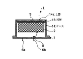
図3は、本発明の第3の実施の形態で、図1の圧電振動子1に若干の変更を加えて、その圧電振動子1をケース14に組み込んだ超音波送受波器の断面図である。図3において図1及び図2と同一符号を付したものは、図1と同一の材料で、また同じ役目を持って形成されているものであるので、その重複説明は省略し、異なる点だけ説明する。ケース14は上面14aに音響整合層配置部としての凹所15を設けて上面14aの全体が閉じられ、概略筒状をしたケースとして形成されているとともに、下面は蓋板7で閉じられて、気体遮蔽性容器として形成されている。なお、凹所15の深さは、超音波発振波長の4分の1深さで形成されており、そのケース14は第1の実施の形態のケース4と同様に、導電材材料、例えば外部の流体に対して信頼性が確保できる金属等の材料で作らている。そして、圧電振動子1は、ケース14の内部で上面14aに圧電体2を貼り付け、外部の凹部15内に音響整合層3を貼り付けた構造になっている。このように構成されている超音波送受波器でも、駆動端子6a,6bに超音波送受波器の共振周波数近傍の周波数の交流信号成分を持つバースト信号電圧を印加すると、圧電振動子1は厚み振動モードで振動し、気体または液体中等の流体中にバースト状の超音波を放射することになる。
【0028】
(第4の実施の態様)
図4は、本発明の第4の実施の形態で、図3に示した超音波送受波器における音響整合層3の上面全体を覆った状態にして保護層5を設け、音響整合層3を音響層配置部である凹所15内に封止した構造にしたもので、それ以外の構造は図3に示した第3の実施の形態の超音波送受波器の構造と同じである。このように構成されている超音波送受波器でも、駆動端子6a,6bに超音波送受波器の共振周波数近傍の周波数の交流信号成分を持つバースト信号電圧を印加すると、圧電振動子1は厚み振動モードで振動し、気体または液体中等の流体中にバースト状の超音波を放射することになる。
【0029】
次に、図1乃至図4に示した音響整合層3を製造し、それを圧電体2あるいはケース14に貼り付ける方法の実施例について説明する。
(実施例1)
図5は第1の実施例で、音響整合層3を製造し、それを圧電子2に貼り付ける方法を工程順に示している説明図である。その第1の実施例を工程1〜工程6の順に説明する。
・工程1:ケイ酸ソーダの電気透析を行い、pH9〜10のケイ酸水溶液を作る。
・工程2:ケイ酸水溶液のpHを5.5に調整し、それを型に流し込む(注型)。そうすると、ケイ酸水溶液が時間と共にゲル化された水性湿潤ゲルブロックを得る。
・工程3:ゲル化されたケイ酸水溶液をトリメチルクロルシラン(TMSC)のアセトン溶液にて疎水化し、脱水処理を行い、湿潤ゲルブロックを作る。
・工程4:湿潤ゲルブロックを二酸化炭素を使用して超臨界乾燥させ、シリカ乾燥ゲルブロックを作る。
・工程5:シリカ乾燥ゲルブロックをλ/4の厚みにカッティングし、所定の音響整合層3を形成する。
・工程6:工程5でカッティングされた音響整合層3を圧電体2の一面あるいはケース14の上面14aに、銀ロウ付けあるいは接着剤で貼り付けると圧電振動子1が出来上がる。
【0030】
(実施例2)
図6は第2の実施例で、音響整合層3を製造し、それを金属密封型のケース14に貼り付ける方法を工程順に示している説明図である。その第2の実施例を工程1〜工程7の順に説明する。
・工程1:テトラエトキシシランとアルミニウム−sec−ブトキシド、エタノールからゾル溶液を形成する。
・工程2:ゾル溶液にゲル化触媒、または酸または塩基を加え、ケース14に増粘状態で塗布するための、ゲル化開始前の塗布原料液を作る。
・工程3:ケース14の塗布面に塗布原料液を塗布し、ケース(密閉容器)14との複合化を図る。
・工程4:塗布原料液の塗布後、ゲル化されるときに、ケース14の表面のOH基と原料のアルコキシ基が反応して化学結合し、ケース14の表面に湿潤ゲル膜を形成する。
・工程5:エタノールで洗浄し、洗浄後に超臨界乾燥した後に、トリメチルクロルシランの蒸気にて疎水処理して、ケース14の表面にアルミノシリカ乾燥ゲル膜を形成する。
・工程6:ケース14の表面に作られたアルミノシリカ乾燥ゲル膜の上に、真空中で乾式の保護膜(保護層5)を形成する。この保護膜5は、酸化ケイ素の蒸着、スパッタリング、あるいはCVDなどにより形成する。
・工程7:その後、ケース14に圧電体2、蓋板7、駆動端子6a,6b等を組み付けると圧電振動子1が出来上がる。
【0031】
(実施例3)
図7は第3の実施例で、音響整合層3を製造し、それを金属密封型のケース14、特にそのケース14をステンレス製のケースとした場合に、そのケース14に音響整合層3を貼り付ける方法を工程順に示している説明図である。その第3の実施例を工程1〜工程6の順に説明する。
・工程1:ケイ酸ソーダの電気透析を行い、pH9〜10のケイ酸水溶液を作る。
・工程2:ケイ酸水溶液のpHを5.5に調整し、それをケース14上に滴下して塗布し、ケイ酸水溶液とケース14との複合化を図る。
・工程3:塗布原料液の塗布後、その塗布原料液がゲル化されるときに、ケース14の表面のOH基と原料のアルコキシ基が反応して化学結合し、ケース14の表面に湿潤ゲル膜が形成される。
・工程4:ゲル化されたケイ酸水溶液をトリメチルクロルシラン(TMSC)のアセトン溶液にて疎水化し、脱水処理を行う。また、ヘキサンに溶媒置換後、100℃に維持した容器中で乾燥し、酸化ケイ素のシリカ乾燥ゲル膜を形成する。
・工程5:ケース14の表面に作られたシリカ乾燥ゲル膜の上に、高周波プラズマCVDによる非結晶炭素(ダイヤモンドライクカーボン)膜の保護膜(保護層5)を形成する。この保護膜5は、硬くて傷が付きにくく、耐薬品性が高い。また、ガスバリア性に優れ、低収着性を有して化学物質が付きにくい。
・工程6:その後、ケース14に圧電体2、蓋板7、駆動端子6a,6b等を組み付けると圧電振動子1が出来上がる。
【0032】
(実施例4)
図8は第4の実施例で、音響整合層3を製造し、それを金属密封型のケース14、特にそのケース14をアルミ製のケースとした場合に、そのケース14に音響整合層3を貼り付ける方法を工程順に示している説明図である。その第4の実施例を工程1〜工程7の順に説明する。
・工程1:トリレンジイソシアネート(TDI)とトルエンジアミン(TDA)をアセトンやテトラヒドロフラン等の非プロトン系溶媒中で混合し、ポリウレア構造を持つ水溶液を作る。この場合の溶媒は、原料と反応しない溶媒を用意することが重要である。
・工程2:水溶液をケース14上に滴下して塗布し、ケース14との複合化を図る。
・工程3:塗布原料液の塗布後、その塗布原料液がゲル化されるときに、ケース14の表面のOH基と原料が反応して化学結合し、ケース14の表面に湿潤ゲル膜が形成される。
・工程4:ゲル化された塗布原料液をターシャルプチルアルコールに溶媒置換後、25℃以下で凍結し、その後、41Torr以下に減圧状態で加熱して乾燥し、有機乾燥ゲル膜を形成する。この有機乾燥ゲル膜は撥水性を有する。
・工程5:ケース14の表面に作られた有機乾燥ゲル膜の上にウレタン系紫外線(UV)硬化樹脂をコーティングして硬化し、保護膜(保護層5)を形成する。・工程6:その後、ケース14に圧電体2、蓋板7、駆動端子6a,6b等を組み付けると圧電振動子1が出来上がる。
【0033】
図9は、本発明の超音波送受波器を用いた超音波流量計を示すブロック図である。図9における超音波流量計は、流量測定部51である管内を被測定流体が速度Vにて図に示す方向に流れるようにして設置される。その流量測定部51の管壁には、本発明の超音波送受波器としての圧電振動子1(1a,1b)が相対して配置されている。ここでは、圧電振動子1aを超音波送波器(以下、「超音波送波器1a」という)として用い、圧電振動子1bを超音波受波器(以下、「超音波受波器1b」という)として用いている。また、超音波送波器1aと超音波受波器1bには、これらの送受信を切り替える切替回路55を介して、超音波送受波器1a,1bを駆動する駆動回路54と、超音波パルスを検知する受信検知回路56、超音波パルスの伝搬時間を計測するタイマ57、該タイマ57の出力より流量を演算する演算部58、駆動回路54とタイマ57に制御信号を出力する制御部59が接続されている。
【0034】
このように構成された超音波流量計の動作を次に説明する。非測定流体を例えばLPガス、超音波送受波器1a,1bの駆動周波数を約500kHzとする。制御部59では駆動回路54に送信開始信号を出力すると同時に、タイマ7の時間計測を開始させる。駆動回路54は送信開始信号を受けると超音波送受波器1aを駆動し、超音波パルスを送信する。送信された超音波パルスは流量測定内を伝搬し、超音波送受波器1bで受信される。受信された超音波パルスは超音波送受波器1bで電気信号に変換され、受信検知回路56に出力される。受信検知回路56では受信信号の受信タイミングを決定し、タイマ57を停止させ、演算部58で伝搬時間t1を演算する。
【0035】
引き続き切替回路55で駆動部54と受信検知回路56に接続する超音波送受波器1a,1bを切り替え、再び制御部59では駆動回路54に送信開始信号を出力すると同時に、タイマ57の時間計測を開始させる。伝搬時間t1の測定と逆に、超音波送受波器1bで超音波パルスを送信し、超音渡送受波器1aで受信し、演算部58で伝搬時間t2を演算する。
【0036】
ここで、超音波送受波器1aと超音渡送受波器1bの中心を結ぶ距離をL、LPガスの無風状態での音速をC、流量測定部51内での流速をV、非測定流体の流れの方向と超音波送受波器1a,1bの中心を結ぶ線との角度をθとすると、伝搬時間t1,t2はそれぞれ求められる。また、距離Lは既知であるので時間t1とt2を測定すれば流速Vが求められ、その流速Vから流量を調べることができることとなる。
【0037】
【発明の効果】
以上説明したように、本発明は、音響整合層が無機酸化物または有機高分子の乾燥ゲルからなり、 乾燥ゲルの固体骨格部が疎水化され、圧電体と音響整合層が化学結合してなる構成を有しているので、疎水化されている乾燥ゲルの固体骨格部により極めて軽量で音響インピーダンスの小さな音響整合層を有する超音波送受波器が得られる。また、乾燥ゲルの均質性の高さから特性バラツキが少ない安定した超音波送受波器が得られる。さらに、無機酸化物または有機高分子の乾燥ゲル形成時に、圧電体表面または容器(ケース)表面のOH基と原料の成分が反応して化学的に結合されて貼り付けられるので、接着層の無い、いわゆる接着層レスの超音波送受波器が得られるという優れた効果も期待できる。
【図面の簡単な説明】
【図1】本発明の第1の形態として示す超音波受波器の断面図
【図2】本発明の第2の形態として示す超音波受波器の断面図
【図3】本発明の第3の形態として示す超音波受波器の断面図
【図4】本発明の第4の形態として示す超音波受波器の断面図
【図5】本発明の超音波受波器における製造方法の第1実施例を説明する工程図
【図6】本発明の超音波受波器における製造方法の第2実施例を説明する工程図
【図7】本発明の超音波受波器における製造方法の第3実施例を説明する工程図
【図8】本発明の超音波受波器における製造方法の第3実施例を説明する工程図
【図9】本発明の超音波送受波器を用いた超音波流量計を示すブロック図
【図10】一般的な超音波流量計の測定原理を示す断面図
【符号の説明】
1 圧電振動子
2 圧電体
3 音響整合層
4 ケース
5 保護層
6a,6b 駆動端子
7 蓋板
14 ケース
14a 上面
15 凹所(音響整合層配置部)
51 流量測定部
54 駆動回路
55 切替回路
56 受信検知回路
57 タイマ(計測回路)
58 演算部
59 制御部[0001]
BACKGROUND OF THE INVENTION
The present invention relates to an ultrasonic transducer for transmitting and receiving ultrasonic waves, a method for manufacturing the ultrasonic transducer, and an ultrasonic flowmeter using the ultrasonic transducer.
[0002]
[Prior art]
2. Description of the Related Art In recent years, ultrasonic flowmeters that measure the time during which ultrasonic waves propagate through a propagation path, measure the moving speed of a fluid, and measure the flow rate are being used in gas meters and the like.
[0003]
FIG. 10 shows the measurement principle of the ultrasonic flowmeter. As shown in FIG. 10, the fluid flows in the pipe at a velocity V in the direction shown in the figure. A pair of
[0004]
The operation is as follows. When an AC voltage having a frequency near the resonance frequency of the
[0005]
Also, in such an ultrasonic flow meter, if an alternating voltage is applied continuously, it is difficult to measure the propagation time because the ultrasonic wave is continuously emitted from the ultrasonic transducer, so it is usually a pulse signal. A burst voltage signal having a carrier wave as a carrier voltage is used as a drive voltage. Hereinafter, the measurement principle will be described in more detail. When a driving burst voltage signal is applied to the
[0006]
In FIG. 10, the flow velocity of the fluid flowing in the pipe is V, the velocity of the ultrasonic wave in the fluid is C, and the angle between the direction of flow of the fluid and the propagation direction of the ultrasonic pulse is θ. When the
[0007]
f1 = 1 / t1 = (C + Vcos θ) / L (1)
[0008]
On the other hand, when the
[0009]
f2 = 1 / t2 = (C−Vcos θ) / L (2)
[0010]
Therefore, the frequency difference Δf between the two sing-around frequencies is expressed by the following equation (3), and the fluid flow velocity V can be obtained from the ultrasonic propagation path distance L and the frequency difference Δf.
Δf = f1-f2 = 2V cos θ / L (3)
[0011]
That is, the flow velocity V of the fluid can be obtained from the distance L of the ultrasonic propagation path and the frequency difference Δf, and the flow rate can be examined from the flow velocity V.
[0012]
In such an ultrasonic flowmeter, accuracy is required, but in order to improve accuracy, an ultrasonic transmission / reception wave that transmits an ultrasonic wave to a gas or receives an ultrasonic wave that has propagated through the gas is received. The acoustic impedance of the matching layer formed on the transmission / reception surface of the ultrasonic wave in the piezoelectric vibrator constituting the container is important. The acoustic impedance of the piezoelectric vibrator generating the ultrasonic vibration is about 30 × 10 6, the acoustic impedance of air is about 400, and the ideal value of the acoustic impedance of the acoustic matching layer is about 0.11 × 10 6. . The acoustic impedance is defined by the following equation (4).
[0013]
Acoustic impedance = (density) x (sound speed)
[0014]
Therefore, in order to keep the acoustic impedance low, the acoustic matching layer is made of a material having a low density, for example, a material obtained by hardening a glass balloon or a plastic balloon with a resin material. In addition, methods such as thermal compression of a hollow glass sphere or foaming of a molten material have been adopted. This can be known from, for example, Japanese Patent No. 2559144.
[0015]
[Problems to be solved by the invention]
However, the acoustic matching layer used in the conventional ultrasonic transducer used in the ultrasonic flowmeter has a method of thermally compressing the hollow glass sphere or foaming the molten material as described above. It was taken. For this reason, there is a problem that the medium tends to be non-homogeneous due to breakage of the glass sphere due to pressure, separation due to insufficient pressure, foaming of the peeled molten material, etc., causing variations in characteristics, which causes variations in equipment accuracy. was there. In addition, since the acoustic matching layer is exposed in the gas, there are problems that the surface collapses due to humidity, deterioration due to a chemically active substance is quick, and durability is poor.
[0016]
The present invention has been made in order to solve such a problem, and the object thereof is to reduce the variation in characteristics, to stabilize the accuracy, and to improve the durability and the like. An ultrasonic transducer, a method for manufacturing the ultrasonic transducer, and an ultrasonic flowmeter are provided.
[0017]
[Means for Solving the Problems]
The ultrasonic transducer of the present invention is an ultrasonic transducer including a piezoelectric body and an acoustic matching layer, wherein the acoustic matching layer is made of a dry gel of an inorganic oxide or an organic polymer, and the solid of the dry gel The skeleton is hydrophobized The piezoelectric body and the acoustic matching layer are chemically bonded. It has the composition which becomes. As another configuration, the piezoelectric body is disposed on the inner surface of the sealed container, and the acoustic matching layer is disposed on the outer surface of the sealed container facing the position of the piezoelectric body. . these According to the configuration, an ultrasonic transducer having an acoustic matching layer with a low acoustic impedance can be obtained by the solid skeleton portion of the dried gel that has been hydrophobized. In addition, due to the high homogeneity of the dried gel, there is little characteristic variation.
[0018]
Moreover, when the ultrasonic transducer of the present invention is embodied as follows, a more preferable ultrasonic transducer is obtained.
・ First Further, the closed container has a concave acoustic matching layer arrangement portion having a quarter depth of the ultrasonic oscillation wavelength at a position of the outer surface facing the arrangement position of the piezoelectric body, and the acoustic matching layer The arrangement part is filled with a dry gel of an inorganic oxide or an organic polymer.
・ No. 2 In addition, the airtight container and the acoustic matching layer are chemically bonded.
・ No. 3 Further, the sealed container is made of a conductive material.
・ No. 4 In addition, the conductive material is a metal material.
・ No. 5 In addition, the dry gel constituting the acoustic matching layer has a density of 500 kg / m 3 or less and an average pore diameter of 100 nm or less.
・ No. 6 In addition, the solid skeleton portion of the dry gel has at least silicon oxide or aluminum oxide as a component.
・ No. 7 And a protective layer having a density of 800 kg / m 3 or more and a thickness of 10 μm or less is formed on the surface of the acoustic matching layer.
・ No. 8 In addition, the protective layer may be a metal material, an inorganic material, or a polymer material.
・ No. 9 In addition, the protective layer is made of any one of aluminum, silicon oxide, aluminum oxide, amorphous carbon, and polyparaxylene.
[0019]
A method for manufacturing an ultrasonic transducer according to the present invention is a method for manufacturing an ultrasonic transducer including an acoustic matching layer made of a dry gel of an inorganic oxide or an organic polymer having a solid skeleton made hydrophobic, and a piezoelectric body. The dry gel is brazed to the piezoelectric body or a gas shielding container having the piezoelectric body disposed on the inner surface. An ultrasonic transducer obtained by using this manufacturing method can achieve high sensitivity and stabilization of characteristics by an acoustic matching layer with low acoustic impedance.
[0020]
A method for manufacturing an ultrasonic transducer according to the present invention is a method for manufacturing an ultrasonic transducer including an acoustic matching layer made of a dry gel of an inorganic oxide or an organic polymer having a solid skeleton made hydrophobic, and a piezoelectric body. A film forming step of applying a gel raw material liquid to a piezoelectric body or a gas shielding container having the piezoelectric body arranged on an inner surface thereof, a solidifying step of obtaining a wet gel from the gel raw material liquid, and a solvent in the wet gel. The acoustic matching layer is formed by including a drying step of removing to obtain a dry gel. An ultrasonic transducer obtained by using this manufacturing method can achieve high sensitivity and stabilization of characteristics by an acoustic matching layer with low acoustic impedance.
[0021]
Moreover, if the manufacturing method of the ultrasonic transducer of the present invention is embodied as follows, a more preferable ultrasonic transducer can be obtained.
First, in the ultrasonic wave transmitter / receiver in which the piezoelectric body is disposed on the inner surface of the sealed container, a quarter of the ultrasonic oscillation wavelength is placed on the outer surface of the sealed container facing the position of the piezoelectric body. It has a concave acoustic matching layer arrangement part having a depth of 1, and the gel raw material liquid is applied to the acoustic matching layer arrangement part.
Second, a protective layer is formed on the surface of the acoustic matching layer by a dry film forming method.
[0022]
The ultrasonic flowmeter according to the present invention includes a flow rate measurement unit through which a fluid to be measured flows, a pair of ultrasonic transducers provided in the flow rate measurement unit to transmit and receive an ultrasonic signal, and the ultrasonic transducer A measurement circuit for measuring the ultrasonic propagation time of the sensor and a flow rate calculation means for calculating a flow rate based on a signal from the measurement circuit, and the ultrasonic transducer cuts off the measurement fluid and the piezoelectric body. It is set as the structure comprised by the sealed container which was made. This ultrasonic flowmeter can improve the stability of flow measurement because the ultrasonic transducer has high sensitivity and little variation in characteristics.
[0023]
DETAILED DESCRIPTION OF THE INVENTION
(First embodiment)
FIG. 1 is a sectional view of a piezoelectric vibrator of an ultrasonic transducer used in an ultrasonic flowmeter according to the first embodiment of the present invention. In FIG. 1, a
[0024]
(Second Embodiment)
FIG. 2 is a sectional view of an ultrasonic transducer using the
[0025]
The protective layer 5 has a density of 800 kg / m. 3 The above is a layer having a thickness of 10 μm or less and made of a metal material, an inorganic material, a polymer material, or the like. Specifically, aluminum, silicon oxide, aluminum oxide, low-melting glass, amorphous carbon, polymer ( In addition to polyparaxylene and polyimide), a coating resin, a UV (ultraviolet) curable resin, a thermosetting resin, and the like are used. Further, when aluminum is used, it is provided by vapor deposition or sputtering, and when silicon oxide or aluminum oxide is used, it is provided by vapor deposition or sputtering, CVD (Chemical Vapor Deposition), etc. . When low-melting glass is used, it is provided by coating, when amorphous carbon is used, it is provided by plasma CVD, and when polymer (polyparaxylene, polyimide) is used, it is provided by vapor deposition polymerization. It is done.
[0026]
In the ultrasonic transducer configured as described above, when a burst signal voltage having an AC signal component having a frequency in the vicinity of the resonance frequency of the ultrasonic transducer is applied to the
[0027]
(Third embodiment)
FIG. 3 is a cross-sectional view of an ultrasonic transducer according to the third embodiment of the present invention, in which the
[0028]
(Fourth embodiment)
FIG. 4 shows a fourth embodiment of the present invention, in which a protective layer 5 is provided so as to cover the entire top surface of the acoustic matching layer 3 in the ultrasonic transducer shown in FIG. The structure is sealed in the
[0029]
Next, an embodiment of a method for manufacturing the acoustic matching layer 3 shown in FIGS. 1 to 4 and attaching the acoustic matching layer 3 to the
Example 1
FIG. 5 is an explanatory diagram showing a method of manufacturing the acoustic matching layer 3 and affixing the acoustic matching layer 3 to the piezoelectric 2 in order of steps in the first embodiment. The 1st Example is demonstrated in order of the process 1-the process 6. FIG.
Step 1: Electrodialyze sodium silicate to make a silicate aqueous solution having a pH of 9-10.
Step 2: Adjust the pH of the aqueous silicic acid solution to 5.5 and pour it into a mold (casting). Then, an aqueous wet gel block is obtained in which the aqueous silicic acid solution is gelled with time.
Step 3: Hydrophobizing the gelled silicic acid aqueous solution with an acetone solution of trimethylchlorosilane (TMSC) and performing dehydration treatment to make a wet gel block.
Step 4: Supercritical dry the wet gel block using carbon dioxide to make a silica dry gel block.
Step 5: A silica dry gel block is cut to a thickness of λ / 4 to form a predetermined acoustic matching layer 3.
Step 6: When the acoustic matching layer 3 cut in Step 5 is attached to one surface of the
[0030]
(Example 2)
FIG. 6 is an explanatory diagram showing a method of manufacturing the acoustic matching layer 3 and affixing the acoustic matching layer 3 to the metal sealed
Step 1: A sol solution is formed from tetraethoxysilane, aluminum-sec-butoxide, and ethanol.
Step 2: Add a gelation catalyst, or acid or base to the sol solution, and prepare a coating raw material solution before the start of gelation to be applied to the
Step 3: A coating raw material solution is applied to the application surface of the
Step 4: When gelation is performed after the application raw material liquid is applied, the OH group on the surface of the
Step 5: Washing with ethanol, supercritical drying after washing, and hydrophobic treatment with vapor of trimethylchlorosilane to form an aluminosilica dry gel film on the surface of the
Step 6: A dry protective film (protective layer 5) is formed in vacuum on the aluminosilica dry gel film formed on the surface of the
Step 7: After that, when the
[0031]
Example 3
FIG. 7 shows a third embodiment in which the acoustic matching layer 3 is manufactured. When the acoustic matching layer 3 is made of a metal-sealed
Step 1: Electrodialyze sodium silicate to make a silicate aqueous solution having a pH of 9-10.
Step 2: The pH of the aqueous silicic acid solution is adjusted to 5.5, which is dropped onto the
Step 3: After the application raw material liquid is applied, when the application raw material liquid is gelled, the OH group on the surface of the
Step 4: Gelled silicic acid aqueous solution is hydrophobized with acetone solution of trimethylchlorosilane (TMSC) and dehydrated. In addition, after replacing the solvent with hexane, it is dried in a container maintained at 100 ° C. to form a silica dry gel film of silicon oxide.
Step 5: Forming a protective film (protective layer 5) of an amorphous carbon (diamond-like carbon) film by high-frequency plasma CVD on the silica dry gel film formed on the surface of the
Step 6: After that, when the
[0032]
Example 4
FIG. 8 shows a fourth embodiment in which the acoustic matching layer 3 is manufactured. When the acoustic matching layer 3 is made of a metal-sealed
Step 1: Tolylene diisocyanate (TDI) and toluenediamine (TDA) are mixed in an aprotic solvent such as acetone or tetrahydrofuran to prepare an aqueous solution having a polyurea structure. In this case, it is important to prepare a solvent that does not react with the raw material.
Step 2: An aqueous solution is dropped onto the
Step 3: After coating the coating raw material liquid, when the coating raw material liquid is gelled, the OH group on the surface of the
Step 4: After replacing the gelated coating raw material solution with tarpyl alcohol, the solution is frozen at 25 ° C. or lower, and then dried by heating under reduced pressure to 41 Torr or lower to form an organic dry gel film. This organic dry gel film has water repellency.
Step 5: A urethane-based ultraviolet (UV) curable resin is coated on the organic dry gel film formed on the surface of the
[0033]
FIG. 9 is a block diagram showing an ultrasonic flowmeter using the ultrasonic transducer of the present invention. The ultrasonic flowmeter in FIG. 9 is installed so that the fluid to be measured flows at a velocity V in the direction shown in FIG. The piezoelectric vibrator 1 (1a, 1b) as the ultrasonic transducer according to the present invention is disposed on the tube wall of the flow
[0034]
Next, the operation of the ultrasonic flowmeter configured as described above will be described. The non-measurement fluid is, for example, LP gas, and the drive frequency of the ultrasonic transducers 1a and 1b is about 500 kHz. The
[0035]
Subsequently, the switching
[0036]
Here, L is the distance connecting the centers of the ultrasonic transducer 1a and the ultrasonic transducer 1b, C is the velocity of sound in the absence of LP gas, V is the flow velocity in the
[0037]
【The invention's effect】
As described above, in the present invention, the acoustic matching layer is made of a dry gel of an inorganic oxide or an organic polymer, and the solid skeleton portion of the dry gel is hydrophobized. The piezoelectric body and the acoustic matching layer are chemically bonded. Therefore, an ultrasonic transducer having an acoustic matching layer that is extremely lightweight and has a small acoustic impedance can be obtained by the solid skeleton portion of the dried gel that has been hydrophobized. In addition, a stable ultrasonic transducer with little variation in characteristics due to the high homogeneity of the dried gel can be obtained. Furthermore, when forming a dry gel of inorganic oxide or organic polymer, the OH group on the surface of the piezoelectric body or the surface of the container (case) reacts with the components of the raw material and is bonded and bonded, so there is no adhesive layer Also, an excellent effect of obtaining a so-called adhesive layer-less ultrasonic transducer can be expected.
[Brief description of the drawings]
FIG. 1 is a cross-sectional view of an ultrasonic receiver shown as a first embodiment of the present invention.
FIG. 2 is a sectional view of an ultrasonic receiver shown as a second embodiment of the present invention.
FIG. 3 is a cross-sectional view of an ultrasonic receiver shown as a third embodiment of the present invention.
FIG. 4 is a cross-sectional view of an ultrasonic receiver shown as a fourth embodiment of the present invention.
FIG. 5 is a process diagram for explaining a first embodiment of a manufacturing method in an ultrasonic wave receiver according to the present invention.
FIG. 6 is a process diagram for explaining a second embodiment of the manufacturing method in the ultrasonic receiver according to the present invention.
FIG. 7 is a process chart for explaining a third embodiment of the manufacturing method for the ultrasonic receiver according to the present invention.
FIG. 8 is a process diagram for explaining a third embodiment of a manufacturing method for an ultrasonic wave receiver according to the present invention.
FIG. 9 is a block diagram showing an ultrasonic flowmeter using the ultrasonic transducer of the present invention.
FIG. 10 is a cross-sectional view showing the measurement principle of a general ultrasonic flowmeter
[Explanation of symbols]
1 Piezoelectric vibrator
2 Piezoelectric material
3 Acoustic matching layer
4 cases
5 Protective layer
6a, 6b Drive terminal
7 Lid
14 cases
14a upper surface
15 recess (acoustic matching layer arrangement part)
51 Flow measurement unit
54 Drive circuit
55 switching circuit
56 Reception detection circuit
57 Timer (measurement circuit)
58 Calculation unit
59 Control unit
Claims (16)
Priority Applications (6)
| Application Number | Priority Date | Filing Date | Title |
|---|---|---|---|
| JP2001056051A JP3611796B2 (en) | 2001-02-28 | 2001-02-28 | Ultrasonic transducer, manufacturing method of ultrasonic transducer, and ultrasonic flowmeter |
| EP02004663A EP1237148A3 (en) | 2001-02-28 | 2002-02-28 | Ultrasonic transducer, method of manufacture, and use in a ultrasonic flowmeter |
| CNB021066760A CN1293371C (en) | 2001-02-28 | 2002-02-28 | Ultrasonic sensor, method for mfg. same and ultrasonic flowmeter |
| KR1020020010904A KR20020070874A (en) | 2001-02-28 | 2002-02-28 | Ultrasonic transducer, method for manufacturing ultrasonic transducer, and ultrasonic flowmeter |
| US10/084,249 US6776051B2 (en) | 2001-02-28 | 2002-02-28 | Ultrasonic transducer and ultrasonic flowmeter using same |
| US10/836,240 US7087264B2 (en) | 2001-02-28 | 2004-05-03 | Ultrasonic transducer, method for manufacturing ultrasonic transducer, and ultrasonic flowmeter |
Applications Claiming Priority (1)
| Application Number | Priority Date | Filing Date | Title |
|---|---|---|---|
| JP2001056051A JP3611796B2 (en) | 2001-02-28 | 2001-02-28 | Ultrasonic transducer, manufacturing method of ultrasonic transducer, and ultrasonic flowmeter |
Publications (2)
| Publication Number | Publication Date |
|---|---|
| JP2002262394A JP2002262394A (en) | 2002-09-13 |
| JP3611796B2 true JP3611796B2 (en) | 2005-01-19 |
Family
ID=18916135
Family Applications (1)
| Application Number | Title | Priority Date | Filing Date |
|---|---|---|---|
| JP2001056051A Expired - Lifetime JP3611796B2 (en) | 2001-02-28 | 2001-02-28 | Ultrasonic transducer, manufacturing method of ultrasonic transducer, and ultrasonic flowmeter |
Country Status (5)
| Country | Link |
|---|---|
| US (2) | US6776051B2 (en) |
| EP (1) | EP1237148A3 (en) |
| JP (1) | JP3611796B2 (en) |
| KR (1) | KR20020070874A (en) |
| CN (1) | CN1293371C (en) |
Families Citing this family (69)
| Publication number | Priority date | Publication date | Assignee | Title |
|---|---|---|---|---|
| DE10133395A1 (en) * | 2001-07-13 | 2003-01-23 | Flowtec Ag | Ultrasonic flow meter sensor has heat conducting moulded mount |
| DK200101780A (en) * | 2001-11-30 | 2002-11-27 | Danfoss As | An ultrasonic transducer |
| EP1382943A1 (en) * | 2002-01-28 | 2004-01-21 | Matsushita Electric Industrial Co., Ltd. | Acoustic matching layer, ultrasonic transmitter-receiver, their manufacturing methods, and ultrasonic flowmeter |
| WO2003064979A1 (en) | 2002-01-28 | 2003-08-07 | Matsushita Electric Industrial Co., Ltd. | Ultrasonic transmitter-receiver and ultrasonic flowmeter |
| JP3602112B2 (en) * | 2002-06-04 | 2004-12-15 | 東京電力株式会社 | Doppler ultrasonic flowmeter, flow measurement method using Doppler ultrasonic flowmeter, and flow measurement program |
| CN1729716A (en) * | 2002-12-20 | 2006-02-01 | 松下电器产业株式会社 | Ultrasonic transmitter/receiver, process for producing the same, and ultrasonic flowmeter |
| EP1610587B1 (en) * | 2003-04-28 | 2011-06-15 | Panasonic Corporation | Ultrasonic sensor |
| US7062972B2 (en) * | 2003-07-21 | 2006-06-20 | Horiba Instruments, Inc. | Acoustic transducer |
| WO2005020631A1 (en) * | 2003-08-22 | 2005-03-03 | Matsushita Electric Industrial Co., Ltd. | Sound matching body, process for producing the same, ultrasonic sensor and ultrasonic wave transmitting/receiving system |
| DE10356114A1 (en) * | 2003-11-27 | 2005-06-23 | Endress + Hauser Flowtec Ag, Reinach | Device for determining and / or monitoring the volume and / or mass flow rate of a measuring medium |
| WO2005068537A1 (en) * | 2004-01-15 | 2005-07-28 | Matsushita Electric Industrial Co., Ltd. | Porous body and method for producing same |
| US6895825B1 (en) * | 2004-01-29 | 2005-05-24 | The Boeing Company | Ultrasonic transducer assembly for monitoring a fluid flowing through a duct |
| JP2005218641A (en) * | 2004-02-05 | 2005-08-18 | Honda Electronic Co Ltd | Ultrasonic probe |
| EP1615203A1 (en) * | 2004-07-07 | 2006-01-11 | Nederlandse Organisatie Voor Toegepast-Natuurwetenschappelijk Onderzoek Tno | Ultrasonic transducer system |
| JP4513596B2 (en) * | 2004-08-25 | 2010-07-28 | 株式会社デンソー | Ultrasonic sensor |
| DE102005003398A1 (en) * | 2005-01-24 | 2006-08-03 | Endress + Hauser Flowtec Ag | Device for determining and / or monitoring volume and / or mass flow |
| JP4873966B2 (en) * | 2006-03-09 | 2012-02-08 | パナソニック株式会社 | Ultrasonic transducer |
| DE102006062706B4 (en) * | 2006-03-30 | 2012-12-06 | Krohne Ag | ultrasonic flowmeter |
| JP2008085413A (en) * | 2006-09-26 | 2008-04-10 | Nippon Dempa Kogyo Co Ltd | Ultrasonic probe and manufacturing method thereof |
| EP1921600A1 (en) * | 2006-11-08 | 2008-05-14 | Nederlandse Organisatie Voor Toegepast-Natuurwetenschappelijk Onderzoek Tno | Ultrasonic transducer |
| JP4888112B2 (en) * | 2006-12-28 | 2012-02-29 | パナソニック株式会社 | Ultrasonic transducer and ultrasonic flowmeter |
| JP4983282B2 (en) * | 2007-02-07 | 2012-07-25 | パナソニック株式会社 | Acoustic matching member |
| US20080236286A1 (en) * | 2007-03-29 | 2008-10-02 | Clive Chemo Lam | Non-destructive tubular testing |
| JP2008263419A (en) * | 2007-04-12 | 2008-10-30 | Matsushita Electric Ind Co Ltd | Acoustic matching body, ultrasonic transmitter/receiver and ultrasonic flow rate flow meter |
| US8042398B2 (en) * | 2007-05-30 | 2011-10-25 | Panasonic Corporation | Ultrasonic receiver |
| JP4702345B2 (en) * | 2007-09-28 | 2011-06-15 | パナソニック株式会社 | Ultrasonic transducer and fluid flow measurement device using it |
| JP4702349B2 (en) * | 2007-10-24 | 2011-06-15 | パナソニック株式会社 | Ultrasonic transducer and ultrasonic flow measuring device using it |
| JP5098790B2 (en) * | 2008-05-08 | 2012-12-12 | コニカミノルタエムジー株式会社 | Organic piezoelectric film, ultrasonic transducer using the same, manufacturing method thereof, ultrasonic probe, and ultrasonic medical diagnostic imaging apparatus |
| JP4806431B2 (en) * | 2008-08-04 | 2011-11-02 | パナソニック株式会社 | Ultrasonic transducer |
| US20110264012A1 (en) * | 2009-10-23 | 2011-10-27 | Frans Lautzenhiser | Compliant couplant with liquid reservoir for transducer |
| US20130072802A1 (en) * | 2010-05-31 | 2013-03-21 | Shin-Etsu Polymer Co., Ltd. | Lens for Ultrasonic Diagnosis Apparatus and Probe for Ultrasonic Diagnosis Apparatus |
| FR2977377B1 (en) * | 2011-06-30 | 2015-04-24 | Commissariat Energie Atomique | HIGH TEMPERATURE ULTRASONIC TRANSLATOR USING BRONZE LITHIUM NIOBATE CRYSTAL WITH GOLD AND INDIUM |
| US8783099B2 (en) * | 2011-07-01 | 2014-07-22 | Baker Hughes Incorporated | Downhole sensors impregnated with hydrophobic material, tools including same, and related methods |
| DE102011120391A1 (en) * | 2011-12-06 | 2013-06-06 | Valeo Schalter Und Sensoren Gmbh | Ultrasonic sensor for a motor vehicle, motor vehicle and method for producing an ultrasonic sensor |
| US9170140B2 (en) * | 2012-05-04 | 2015-10-27 | Cameron International Corporation | Ultrasonic flowmeter with internal surface coating and method |
| US9804126B2 (en) * | 2012-09-04 | 2017-10-31 | Veeco Instruments Inc. | Apparatus and method for improved acoustical transformation |
| DE102012108254A1 (en) | 2012-09-05 | 2014-03-06 | systec Controls Meß- und Regeltechnik GmbH | Ultrasonic transducer and method of making an ultrasonic transducer |
| EP2759807B1 (en) * | 2013-01-29 | 2020-01-15 | Itron Global SARL | Ultrasonic flow meter |
| WO2014136221A1 (en) * | 2013-03-06 | 2014-09-12 | 三菱電機株式会社 | Obstruction detection device |
| CN104395704B (en) * | 2013-03-25 | 2017-05-31 | 株式会社又进 | For the ultrasonic sensor and its manufacture method of high temperature |
| DE102013109349A1 (en) * | 2013-08-29 | 2015-03-05 | Endress + Hauser Flowtec Ag | Ultrasonic transducer and ultrasonic flowmeter |
| CN103471633A (en) * | 2013-09-30 | 2013-12-25 | 江苏德易普传感科技有限公司 | Ultrasonic sensor with heating function |
| CN103743423A (en) * | 2013-12-20 | 2014-04-23 | 常州波速传感器有限公司 | Novel high-frequency ultrasonic sensor |
| CN112893067B (en) | 2014-07-11 | 2022-07-08 | 微创医学科技有限公司 | Multi-cell transducer |
| DE112015003719T5 (en) * | 2014-08-11 | 2017-04-27 | Veeco Instruments Inc. | IMPROVED HOUSING FOR ACOUSTIC GAS CONCENTRATION SENSORS AND FLOW CONTROL |
| US9621973B2 (en) * | 2014-09-22 | 2017-04-11 | Samsung Electronics Company, Ltd | Wearable audio device |
| GB2528338B (en) * | 2014-11-28 | 2016-07-13 | 168 Ultrasound Pte Ltd | Ultrasound apparatus and method |
| US9506790B2 (en) * | 2015-03-24 | 2016-11-29 | Daniel Measurement And Control, Inc. | Transducer mini-horn array for ultrasonic flow meter |
| CA2895361C (en) * | 2015-06-19 | 2023-08-01 | Accutron Instruments Inc. | Method and system for ultrasonic airflow measurements |
| CN105047188A (en) * | 2015-07-13 | 2015-11-11 | 北京信息科技大学 | Piezoelectric composite high-frequency energy transducer with matching layer |
| CN105170436A (en) * | 2015-09-25 | 2015-12-23 | 无锡市博阳超声电器有限公司 | Novel ultrasonic transducer |
| KR101890300B1 (en) * | 2016-12-30 | 2018-09-28 | 공주대학교 산학협력단 | Fuel level and Diameter change instrument use ultrasonic wave |
| EP3471438B1 (en) | 2016-06-09 | 2023-09-27 | Panasonic Intellectual Property Management Co., Ltd. | Laminate, ultrasonic transducer, and ultrasonic flowmeter |
| CN106092230B (en) * | 2016-06-17 | 2022-04-08 | 济南新盛电子科技有限公司 | Ultrasonic gas meter with double acoustic path transducers |
| US10518293B2 (en) | 2016-12-09 | 2019-12-31 | Sensus USA, Inc. | Thickness-planar mode transducers and related devices |
| US10850308B2 (en) | 2017-02-24 | 2020-12-01 | Sensus Spectrum, Llc | Ultrasonic device including acoustically matched regions therein |
| US10551406B2 (en) * | 2017-04-20 | 2020-02-04 | Anemoment Llc | Acoustic structural reflection interference mitigation systems, methods, and devices |
| CN107131653B (en) * | 2017-04-28 | 2020-05-19 | 广东万和新电气股份有限公司 | Control device of gas water heater, gas water heater and calculation method of water flow of gas water heater |
| DE102017010727A1 (en) * | 2017-11-21 | 2019-05-23 | Diehl Metering Gmbh | Measuring device for determining a pressure in a measuring volume |
| CN107990924A (en) * | 2017-12-07 | 2018-05-04 | 广东奥迪威传感科技股份有限公司 | A kind of ultrasonic sensor |
| USD851524S1 (en) | 2018-01-18 | 2019-06-18 | Norgas Metering Technologies, Inc. | Ultrasonic flow meter |
| DE102018206937A1 (en) * | 2018-05-04 | 2019-11-07 | Fraunhofer-Gesellschaft zur Förderung der angewandten Forschung e.V. | An impedance matching device, a converter device, and a method of manufacturing an impedance matching device |
| US11724844B2 (en) | 2018-10-24 | 2023-08-15 | Tetra Laval Holdings & Finance S.A. | Ultrasonic sealing device |
| EP4088122A4 (en) | 2020-01-11 | 2024-01-24 | Li Cor Inc | Wind sensor devices, systems, and methods |
| US11703581B2 (en) * | 2020-04-14 | 2023-07-18 | Honda Electronics Co., Ltd. | Ultrasonic transducer for a measuring device |
| CN114441028B (en) * | 2020-10-30 | 2024-04-23 | 深圳富桂精密工业有限公司 | Stamping abnormality detection system |
| CN112414482A (en) * | 2020-11-10 | 2021-02-26 | 宁波智复物联科技有限公司 | Ultrasonic fluid metering transducer based on digital technology |
| EP4056960B1 (en) * | 2021-03-11 | 2023-11-15 | SICK Engineering GmbH | Ultrasonic transducer for transmitting and / or receiving ultrasonic waves |
| CN115175054A (en) * | 2022-06-30 | 2022-10-11 | 歌尔股份有限公司 | Shell of sound generating device, sound generating device with shell and electronic equipment |
Family Cites Families (19)
| Publication number | Priority date | Publication date | Assignee | Title |
|---|---|---|---|---|
| US3546012A (en) * | 1968-03-27 | 1970-12-08 | Atomic Energy Commission | Lithium sulphate ultrasonic transducer |
| US3487137A (en) * | 1968-04-30 | 1969-12-30 | Hewlett Packard Co | Method of producing ultrasonic energy absorbing material |
| SE451149B (en) * | 1983-01-26 | 1987-09-07 | Mo Och Domsjoe Ab | APPARATUS FOR CONTINUOUS TREATMENT OF WATER-INHALING LIGNOCELLULOSAMATER WITH NITRO OXIDE AND ACID |
| US4523122A (en) * | 1983-03-17 | 1985-06-11 | Matsushita Electric Industrial Co., Ltd. | Piezoelectric ultrasonic transducers having acoustic impedance-matching layers |
| US4701659A (en) * | 1984-09-26 | 1987-10-20 | Terumo Corp. | Piezoelectric ultrasonic transducer with flexible electrodes adhered using an adhesive having anisotropic electrical conductivity |
| JPS6449785A (en) | 1987-08-17 | 1989-02-27 | Takenaka Komuten Co | Displacement absorbing piping structure |
| JP2703295B2 (en) | 1988-11-22 | 1998-01-26 | 株式会社東芝 | Image signal processing device |
| JPH02141194U (en) | 1989-04-27 | 1990-11-27 | ||
| FR2665699A1 (en) * | 1990-08-07 | 1992-02-14 | Thomson Csf | PIEZOELECTRIC CERAMIC WITH CONTROLLED POROSITY. |
| EP0497966B1 (en) * | 1990-08-23 | 1997-10-29 | THE REGENTS OF THE UNIVERSITY OF CALIFORNIA as represented by Lawrence Livermore National Laboratory | A METHOD FOR PRODUCING METAL OXIDE AEROGELS HAVING DENSITIES LESS THAN 0.02 g/cm?3 |
| US5437194A (en) * | 1991-03-18 | 1995-08-01 | Panametrics, Inc. | Ultrasonic transducer system with temporal crosstalk isolation |
| US5311095A (en) * | 1992-05-14 | 1994-05-10 | Duke University | Ultrasonic transducer array |
| US5434827A (en) * | 1993-06-15 | 1995-07-18 | Hewlett-Packard Company | Matching layer for front acoustic impedance matching of clinical ultrasonic tranducers |
| EP0640564A1 (en) * | 1993-08-19 | 1995-03-01 | Siemens Aktiengesellschaft | Process for the preparation of a hydrophobic aerogel |
| EP1754958A1 (en) * | 1995-12-13 | 2007-02-21 | Matsushita Electric Industrial Co., Ltd. | Ultrasonic flowmeter and ultrasonic transducer |
| JP3518268B2 (en) * | 1997-08-20 | 2004-04-12 | 松下電器産業株式会社 | Ultrasonic flow meter |
| US6280388B1 (en) * | 1997-11-19 | 2001-08-28 | Boston Scientific Technology, Inc. | Aerogel backed ultrasound transducer |
| US6106474A (en) * | 1997-11-19 | 2000-08-22 | Scimed Life Systems, Inc. | Aerogel backed ultrasound transducer |
| JP3533941B2 (en) * | 1998-05-08 | 2004-06-07 | 松下電器産業株式会社 | Ultrasonic flow meter |
-
2001
- 2001-02-28 JP JP2001056051A patent/JP3611796B2/en not_active Expired - Lifetime
-
2002
- 2002-02-28 CN CNB021066760A patent/CN1293371C/en not_active Expired - Lifetime
- 2002-02-28 KR KR1020020010904A patent/KR20020070874A/en not_active Application Discontinuation
- 2002-02-28 EP EP02004663A patent/EP1237148A3/en not_active Withdrawn
- 2002-02-28 US US10/084,249 patent/US6776051B2/en not_active Expired - Lifetime
-
2004
- 2004-05-03 US US10/836,240 patent/US7087264B2/en not_active Expired - Lifetime
Also Published As
| Publication number | Publication date |
|---|---|
| EP1237148A3 (en) | 2013-03-06 |
| US20020124662A1 (en) | 2002-09-12 |
| JP2002262394A (en) | 2002-09-13 |
| US6776051B2 (en) | 2004-08-17 |
| EP1237148A2 (en) | 2002-09-04 |
| CN1373348A (en) | 2002-10-09 |
| US7087264B2 (en) | 2006-08-08 |
| CN1293371C (en) | 2007-01-03 |
| KR20020070874A (en) | 2002-09-11 |
| US20040200056A1 (en) | 2004-10-14 |
Similar Documents
| Publication | Publication Date | Title |
|---|---|---|
| JP3611796B2 (en) | Ultrasonic transducer, manufacturing method of ultrasonic transducer, and ultrasonic flowmeter | |
| US7389569B2 (en) | Method for manfacturing an acoustic matching member | |
| JP3552054B2 (en) | Acoustic matching layer and ultrasonic transducer | |
| US11162829B2 (en) | Multilayer body that includes piezoelectric body | |
| JP3764162B2 (en) | Ultrasonic transducer, method of manufacturing the same, and ultrasonic flow meter | |
| JP6032512B1 (en) | Laminate, ultrasonic transducer and ultrasonic flowmeter | |
| US20080163691A1 (en) | Ultrasonic Receiver | |
| JP4080374B2 (en) | Acoustic matching member, ultrasonic transducer, ultrasonic flow meter, and manufacturing method thereof | |
| JP4014940B2 (en) | Acoustic matching member, ultrasonic transducer, ultrasonic flow meter, and manufacturing method thereof | |
| JP2005037219A (en) | Ultrasonic transmitter/receiver and manufacturing method therefor | |
| JP2004029038A (en) | Ultrasonic flowmeter | |
| JP4153796B2 (en) | Ultrasonic transducer and ultrasonic flowmeter | |
| JP6751898B2 (en) | Laminates, ultrasonic transmitters and receivers and ultrasonic flowmeters | |
| JP2006030142A (en) | Ultrasonic flowmeter | |
| JP2003329501A (en) | Acoustic matching member, ultrasonic wave transceiver, and ultrasonic wave flowmeter | |
| JP2003284191A (en) | Acoustic matching member, manufacturing method therefor, ultrasonic wave transceiver employing the same, and ultrasonic wave flowmeter | |
| JP3680635B2 (en) | Ultrasonic sensor, ultrasonic sensing device and ultrasonic flow meter |
Legal Events
| Date | Code | Title | Description |
|---|---|---|---|
| A977 | Report on retrieval |
Free format text: JAPANESE INTERMEDIATE CODE: A971007 Effective date: 20040720 |
|
| A131 | Notification of reasons for refusal |
Free format text: JAPANESE INTERMEDIATE CODE: A131 Effective date: 20040727 |
|
| A521 | Request for written amendment filed |
Free format text: JAPANESE INTERMEDIATE CODE: A523 Effective date: 20040916 |
|
| TRDD | Decision of grant or rejection written | ||
| A01 | Written decision to grant a patent or to grant a registration (utility model) |
Free format text: JAPANESE INTERMEDIATE CODE: A01 Effective date: 20041019 |
|
| A61 | First payment of annual fees (during grant procedure) |
Free format text: JAPANESE INTERMEDIATE CODE: A61 Effective date: 20041020 |
|
| R150 | Certificate of patent or registration of utility model |
Free format text: JAPANESE INTERMEDIATE CODE: R150 Ref document number: 3611796 Country of ref document: JP Free format text: JAPANESE INTERMEDIATE CODE: R150 |
|
| FPAY | Renewal fee payment (event date is renewal date of database) |
Free format text: PAYMENT UNTIL: 20081029 Year of fee payment: 4 |
|
| FPAY | Renewal fee payment (event date is renewal date of database) |
Free format text: PAYMENT UNTIL: 20091029 Year of fee payment: 5 |
|
| FPAY | Renewal fee payment (event date is renewal date of database) |
Free format text: PAYMENT UNTIL: 20091029 Year of fee payment: 5 |
|
| FPAY | Renewal fee payment (event date is renewal date of database) |
Free format text: PAYMENT UNTIL: 20101029 Year of fee payment: 6 |
|
| FPAY | Renewal fee payment (event date is renewal date of database) |
Free format text: PAYMENT UNTIL: 20111029 Year of fee payment: 7 |
|
| FPAY | Renewal fee payment (event date is renewal date of database) |
Free format text: PAYMENT UNTIL: 20121029 Year of fee payment: 8 |
|
| FPAY | Renewal fee payment (event date is renewal date of database) |
Free format text: PAYMENT UNTIL: 20131029 Year of fee payment: 9 |
|
| EXPY | Cancellation because of completion of term |