JP3611692B2 - Mechanical brake mechanism of linear motor traveling shaft - Google Patents
Mechanical brake mechanism of linear motor traveling shaft Download PDFInfo
- Publication number
- JP3611692B2 JP3611692B2 JP28128996A JP28128996A JP3611692B2 JP 3611692 B2 JP3611692 B2 JP 3611692B2 JP 28128996 A JP28128996 A JP 28128996A JP 28128996 A JP28128996 A JP 28128996A JP 3611692 B2 JP3611692 B2 JP 3611692B2
- Authority
- JP
- Japan
- Prior art keywords
- linear motor
- suction
- fixed magnet
- suction member
- mechanical brake
- Prior art date
- Legal status (The legal status is an assumption and is not a legal conclusion. Google has not performed a legal analysis and makes no representation as to the accuracy of the status listed.)
- Expired - Fee Related
Links
Images


Description
【0001】
【発明の属する技術分野】
本発明はリニアモータ走行軸の機械ブレーキ機構に関し、更に詳しく言えば、リニアモータに装備されているマグネットの吸引力を利用したリニアモータ走行軸の機械ブレーキ機構に関する。本発明は、例えば工作機械や産業機械の移動機構に適用して有利なものである。
【0002】
【従来技術】
周知のように、リニアモータには、固定マグネットあるいはコイルを備えた固定スライダを配設した軌道に沿って可動スライダを移動させるような推進力が直接的に得られるという特徴がある。そのため、リニアモータが開発されて以来、工作機械など一般機械の駆動源として広範に採用されることが期待されてきた。ところが、一般機械へのリニアモータの採用は期待されていた程には進んでいない。
【0003】
その一因として、リニアモータで駆動される走行軸について機械ブレーキの導入が遅れているということがあげられる。言うまでもなく、リニアモータは機械ブレーキを用いなくとも電気的に急減速・急停止を行なうことが出来るが、それはリニアモータがコントローラの制御下にある場合に限られる。即ち、リニアモータの動作中に停電・断線等の事故が生じ、リニアモータを制御する信号が途絶えた時には、コントローラによる操作が不能になって可動スライダが惰走を続ける事態に至る可能性が高い。
【0004】
従って、電気的ブレーキ以外に減速・停止手段を持たないリニアモータ走行軸を一般機械に採用した場合、「電源を落とせば止まる」という一般機械にとって基本的に備わっているべき機能が欠如することになり、作業者や周辺機器に対する安全の確保が難かしくなる。この問題の最も一般的な解決手段として、リニアモータ走行軸にエアシリンダで駆動されるブレーキ摩擦部材を設け、これを周辺に配備された外部摩擦係合部材に押し付けることで制動を行なうことが考えれる。
【0005】
しかし、エアシリンダは大きな制動力が容易に得られるという利点が存在する反面、エア移動に要する時間を考慮すると応答性に難がある。また、電気とともにエアが遮断された場合であっても、非常ブレーキだけは必ず作動しなければ信頼性のある安全機構と言えない。これらの理由から、エアシリンダを非常時に作動するブレーキのアクチュアータに採用することには問題がある。
【0006】
その他、電磁石とバネを利用した電磁ブレーキ機構を設ける方法や、油圧機構を用いる方法もあるが、ブレーキ作動時に大きな面圧を保持するとなると走行装置全体の大型化が避けられず、実用化が困難であった。
【0007】
【発明が解決しようとする課題】
本発明の目的は、走行装置全体の大型化を伴うことなく、簡便な構造で応答性良く十分な制動力を得ることが可能なリニアモータ走行軸の機械ブレーキ機構を提供することにある。
【0008】
【課題を解決するための手段】
本発明に従ってリニアモータ走行軸に装備される機械ブレーキ機構は、磁場感応吸引性を有する吸引部材と、リニアモータ走行軸の走行スライダに吸引部材を、リニアモータ走行軸に沿って配設された固定マグネットに対して離接可能に支持する吸引部材支持手段と、吸引部材を固定マグネットに対して離隔した位置に解除可能に保持する吸引部材離隔保持手段と、吸引部材上に設けられた摩擦部材と、リニアモータ走行軸に沿って配設され、摩擦部材と摩擦係合可能な外部摩擦係合部材と、吸引部材を前記固定マグネットから離隔する方向に駆動するための外部アクチュエータ手段を備えている。
【0009】
そして、リニアモータ走行軸の電源遮断時あるいは緊急停止必要時には、吸引部材離隔保持手段の吸引部材離隔保持機能が解除され、吸引部材が固定マグネットに対して近接する位置まで自発的に移動し、吸引部材と前記固定マグネットの間に作用する磁気吸引力によって摩擦部材が前記外部摩擦係合部材に対して押し付けられるようになっている。
【0010】
典型的な実施形態においては、吸引部材支持手段に伸張性の弾性部材が用いられ、吸引部材離隔保持手段には、給電時に吸引部材を固定マグネットに対して離隔した位置に保持し、非給電時に吸引部材離隔保持機能が解除される電磁石手段が用いられる。
【0011】
また、外部アクチュエータ手段はエアシリンダ機構を備えていることが好ましい。そして、吸引部材と固定マグネットの間には、吸引部材と固定マグネットの直接接触を防止するシート部材が介在していることが好ましい。
【0012】
本発明の機械ブレーキ機構は、本来リニアモータの駆動に必要な固定マグネットを制動力を生み出すソースとして兼用するので、これまでのように大きな制動力を得るための外部アクチュエータを設ける必要がない。また、電源遮断時には吸引部材離隔保持手段の吸引部材離隔保持機能が解除され、確実にブレーキを有効化される。
【0013】
【発明の実施の形態】
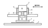
以下、図1〜図4を参照して本発明の一実施形態について説明する。なお、各要素に付されている符号は、図1〜図4を通して共通である。先ず図1及び図2は、本実施形態に係る機械ブレーキ機構を装備したリニアモータ走行軸の走行中の状態を描いた図であり、図1には本体部の概略構造が走行方向に沿った断面図で示され、図2には同じく本体部の概略構造が走行方向に垂直な方向に沿った断面図で示されている。
【0014】
図1あるいは図2において、符号1で指示された走行スライダ(可動スライダ)はリニアガイド7を両側部に備えており、リニアガイド7は設置面上に敷設された2本のガイドレール10の各々に滑働自在に係合している。両ガイドレール10間には、極性を交互にとった多数の永久磁石セグメントで構成される固定マグネット4が配設されている。
【0015】
走行スライダ1の内部には、励磁時に固定マグネット4との相互作用によって走行軸方向(図2では紙面垂直方向)のリニアモータ推力を発生するようにコイル(図示省略)が設けられている。励磁電流は、電源部からコントローラを介して周知の態様で供給される。
【0016】
このような基本構成を持つリニアモータ走行軸に機械ブレーキ機構を装備させるために、走行スライダ1には伸張性のコイルバネ8を介して吸引板3が可動に結合されている。吸引板3はその少なくとも一部は例えば鉄のような磁場感応吸引性(磁場に感応して吸引される性質)を有する材料で構成され、両側部に摩擦部材5が設けられている。そして、走行スライダ1の走行時に摩擦部材5に対向する設置面上の帯状領域には、ブレーキ有効時に摩擦部材5が押し付けられる外部摩擦係合部材11が敷設されている。また、吸引板3と固定マグネット4の一方または双方には、それらを直接接触による損傷から防護するためのシート部材2が設けられている。
【0017】
更に、走行スライダ1は、コイルバネ8に並ぶ位置に吸引板保持用電磁石6を備えている。この吸引板保持用電磁石6は、機械ブレーキ有効時を除き、電源部からコントローラを介して励磁電流の供給を受け、コイルバネ8の伸張力とブレーキユニット全体の重量に打ち勝って吸引板3を引き寄せる力を発生し、吸引板3を固定マグネット4から離隔した位置で吸着保持する。
【0018】
これに応じて摩擦部材5と外部摩擦係合部材11は離隔した状態を維持する。また、吸引板3がこの離隔位置で固定マグネット4から受ける吸引力は非常に弱く、実質的に走行スライダを制動する用は生じない。このようにして、リニアモータ走行時あるいは吸引板保持用電磁石6への給電が維持される通常の停止時には、機械ブレーキは非有効の状態に保たれ、摩擦部材5と外部摩擦係合部材11は離隔した状態を維持する。
【0019】
本実施形態における機械ブレーキ機構は、一旦有効化されたブレーキを解除するためのブレーキ解除手段としてエアシリンダ機構9を備えている。エアシリンダ機構9の要部は、本体部90、ピストン91、並びに空洞92とそれを狭くした肩部94を有するシリンダ部材93で構成されている。本体部90は支持部材12を介して走行スライダ1側にに固定される一方、シリンダ部材93は吸引板3に固定されるとともに、適当な軸受け(図示省略)を介して走行スライダ1に挿嵌されている。本体部90には、圧搾エアで駆動される周知のピストン伸縮機構が内蔵されている。
【0020】
本体部90のピストン伸縮機構がコントローラからのエア供給信号で作動すると、ピストン91が空洞92内を図中上方に滑動する。ピストン91がシリンダ部材93の肩部94に当接して更に滑動を続けると、シリンダ部材93に結合された吸引板3が図中上方へ駆動される(固定マグネット4からの引き離し)。
【0021】
次に、図3及び図4を参照図に加えて本実施形態における機械ブレーキ機構の有効化並びに非有効化(解除)時の動作について説明する。図3は、図1、図2を参照して説明したリニアモータ走行軸の機械ブレーキを有効化した状態を図2と同様の断面図で示したものである。また、図4は図3に示したブレーキ有効状態を解除した状態を図2、図3と同様の断面図で示したものである。なお、図3、図4では、コントローラ/電源との接続関係の記載を省略した。
【0022】
今、図1、図2に示した走行中の状態において、コントローラの故障、断線、停電等の事故、あるいは緊急停止ボタンの押下などによってすべての電源が断たれた場合を考えると、これに応答して次の事象が迅速且つ自発的に生じ、リニアモータ(リニアスライダ1)は直ちに停止に至る。
【0023】
先ず、リニアスライダ1内のコイルへの給電停止に伴いリニア推力が失われ、リニアスライダ1は惰走状態(正確に言えば、若干の制動状態)に入る。これと同時に吸引板保持用電磁石6への給電が断たれるために、吸引板3の吸着機能が失われ、コイルバネ8の伸張力と重力作用によって、吸引板3、摩擦部材5を含むブレーキユット全体が設置面に向けて移動を開始する。
【0024】
吸引板3が固定マグネット4に接近するに従い、磁場感応吸引性を有する吸引板3は固定マグネット4に強く吸引されるようになり、両者の接近運動は加速する。やがて、図3に示されているように、両側部に設けられている摩擦部材5が外部摩擦係合部材11に当接し、次いで強く押し付けられる。これによって、摩擦部材5と外部摩擦係合部材11の間の摩擦に基づく強力な制動作用が発揮され、走行スライダ1は急減速し、短時間の内に停止に至る。
【0025】
走行スライダ1が停止に至った以後も、吸引板3と固定マグネット4の吸引力は維持され、摩擦部材5と外部摩擦係合部材11の間の押し付け状態が保たれるから、ブレーキ有効の状態が自然に維持される。即ち、外部アクチュエータの動作に全く頼ることなく、機械ブレーキが有効化され、且つ、安定的に維持される。
【0026】
図3に示したブレーキ有効状態を解除するには、外部アクチュエータとしてエアシリンダ部材機構が援用される。即ち、ブレーキ解除時には吸引板保持用電磁石6への給電を再開するとともに、エアシリンダ機構9を動作させ、ピストン91を図中上方に駆動する。ピストン91がシリンダ部材93の肩部94に当接して以後は、シリンダ部材93に結合された吸引板3が図中上方へ強く引き上げる力を受け、固定マグネット4からの吸引力に打ち勝って固定マグネット4から引き離され、これと同時に摩擦部材5が外部摩擦係合部材11から離脱し、摩擦係合が解除される。
【0027】
吸引板3が固定マグネット4から十分遠ざかり、吸引板保持用電磁石6の吸引力のみでブレーキユニットを保持出来るようになったならば、エアシリンダ機構9によるピストン91の駆動は停止され、走行スライダ1内のコイルに給電すれえば直ちに走行スライダ1の走行が可能な状態に復帰する。
【0028】
最後に、本実施形態において外部アクチュエータとして使用されているエアシリンダに関連して若干の補足説明をしておく。各図に示されているエアシリンダ機構本体部90はそれ自体完結した駆動機構であり、その他の関連要素91〜94についてエアの出入りはない。ピストン91はエアシリンダ機構本体部90のロッドに直結されており、エアシリンダ機構本体部90内部(シリンダ要素の空洞部)へのエアの出入りによってピストン91が駆動される。
【0029】
また、スライダ走行時(図2参照)には、ピストン91と肩部94の間に空洞92があり、ブレーキ作動時(図3参照)には、吸引板3及び摩擦部材5を含むブレーキユニット全体が設置面に向けて移動した分だけ、ピストン91と吸引板3の間に空洞92が生じると考えることが出来る。
【0030】
スライダ走行時にはピストン91は伸張状態(垂下した状態)としておき、ブレーキが作動してユニット全体が移動する際にピストン91と肩部94が接触しないようにする。そして、上述したように、ブレーキ解除時にはエアシリンダ(本体部90)を動作させて、ピストン91を肩部94に係合させてブレーキユニット全体を引き上げる。
【0031】
電磁石6に通電し、ブレーキユニット全体が保持された後、再度エアシリンダ(本体部90)を動作させてピストン91を伸張させれば、ピストン91が肩部94から離れ、通常動作(走行)の再開可能な状態となる。
【0032】
以上、本発明の一実施形態について説明したが、本発明の眼目はあくまで制動力のソースを吸引部材(上記実施形態では吸引板3)と固定マグネットの間に作用する磁気吸引力に求める点にあり、上記実施形態は本発明を限定するものではない。従って、十分な磁気吸引力が吸引部材(吸引板3)と固定マグネットの間に作用する条件が満たされるのであれば、コイルバネ8は必ずしも伸張性のものである必要はなく、場合によっては吸引部材を固定マグネットに対して離接可能に支持する手段(例えば吸引部材のガイド機構)が採用されても良い。
【0033】
ブレーキ解除のための外部アクチュエータについては、上記実施形態のようにエアシリンダ機構を用いることが好ましいが、他の型のアクチュエータ(例えば吸引部材を駆動する電磁プランジャ)を用いることも可能である。
【0034】
【発明の効果】
本発明によれば、本来リニアモータの駆動に必要な固定マグネットを制動力を生み出すソースに兼用されるので、応答性良く大きな制動力が得られるコンパクトな機械ブレーキ機構を提供することが出来る。また、本発明の機械ブレーキ機構は、電源遮断時に自動的にブレーキを有効化することが出来るので、リニアモータ走行軸を用いた装置の安全性を高めることが出来る。
【図面の簡単な説明】
【図1】本発明の実施形態に係る機械ブレーキ機構を装備したリニアモータ走行軸について、走行時の状態を走行方向に沿った断面図で示した図である。
【図2】本発明の実施形態に係る機械ブレーキ機構を装備したリニアモータ走行軸について、走行時の状態を走行方向に垂直な方向に沿った断面図で示した図である。
【図3】本発明の実施形態に係る機械ブレーキ機構を装備したリニアモータ走行軸について、ブレーキ有効時の状態を走行方向に垂直な方向に沿った断面図で示した図である。
【図4】本発明の実施形態に係る機械ブレーキ機構を装備したリニアモータ走行軸について、ブレーキ解除時の状態を走行方向に垂直な方向に沿った断面図で示した図である。
【符号の説明】
1 走行スライダ
2 シート部材
3 吸引板
4 固定マグネット
5 摩擦部材
6 吸引板保持用電磁石
7 リニアガイド
8 コイルバネ
9 エアシリンダ機構
10 ガイドレール
11 外部摩擦係合部材
12 支持部材
90 エアシリンダ機構本体部
91 ピストン
92 空洞
94 肩部
93 シリンダ部材[0001]
BACKGROUND OF THE INVENTION
The present invention relates to a mechanical brake mechanism for a linear motor travel shaft, and more particularly to a mechanical brake mechanism for a linear motor travel shaft that uses the attractive force of a magnet provided in the linear motor. The present invention is advantageous when applied to a moving mechanism of a machine tool or an industrial machine, for example.
[0002]
[Prior art]
As is well known, a linear motor is characterized in that a propulsive force that directly moves a movable slider along a track on which a fixed slider having a fixed magnet or a coil is disposed can be obtained. Therefore, since the linear motor was developed, it has been expected to be widely used as a drive source for general machines such as machine tools. However, the adoption of linear motors in general machines has not progressed as much as expected.
[0003]
One reason is that the introduction of the mechanical brake is delayed for the traveling shaft driven by the linear motor. Needless to say, the linear motor can be electrically decelerated and stopped without using a mechanical brake, but only when the linear motor is under the control of the controller. That is, when an accident such as a power failure or disconnection occurs during the operation of the linear motor and the signal for controlling the linear motor is interrupted, there is a high possibility that the operation by the controller becomes impossible and the movable slider continues to coast. .
[0004]
Therefore, when a linear motor traveling shaft that does not have a deceleration / stop means other than an electric brake is adopted for a general machine, the function that should be basically provided for a general machine that “stops when the power is turned off” is lacking. Therefore, it is difficult to ensure safety for workers and peripheral devices. As the most general solution to this problem, it is considered to provide a brake friction member driven by an air cylinder on the linear motor traveling shaft and perform braking by pressing it against an external friction engagement member arranged in the vicinity. It is.
[0005]
However, while the air cylinder has an advantage that a large braking force can be easily obtained, the response is difficult in consideration of the time required for air movement. Even if air is shut off together with electricity, the emergency brake alone cannot be said to be a reliable safety mechanism unless it always operates. For these reasons, there is a problem in adopting an air cylinder as an actuator for a brake that operates in an emergency.
[0006]
In addition, there are a method of providing an electromagnetic brake mechanism using an electromagnet and a spring, and a method of using a hydraulic mechanism. However, if a large surface pressure is maintained during brake operation, the overall traveling device is inevitably increased in size and difficult to put into practical use. Met.
[0007]
[Problems to be solved by the invention]
An object of the present invention is to provide a mechanical brake mechanism for a linear motor traveling shaft that can obtain a sufficient braking force with a simple structure and good response without increasing the size of the entire traveling device.
[0008]
[Means for Solving the Problems]
According to the present invention, a mechanical brake mechanism equipped on a linear motor travel shaft includes a suction member having a magnetic field sensitive suction property, a fixed member disposed along the linear motor travel shaft, and a suction member on a travel slider of the linear motor travel shaft. A suction member supporting means for releasably supporting the magnet; a suction member separation holding means for releasably holding the suction member at a position separated from the fixed magnet; and a friction member provided on the suction member; And an external friction engagement member disposed along the linear motor traveling axis and capable of friction engagement with the friction member, and an external actuator means for driving the suction member in a direction away from the fixed magnet.
[0009]
When the power of the linear motor traveling shaft is cut off or when an emergency stop is required, the suction member separation holding function of the suction member separation holding means is released, and the suction member moves spontaneously to a position close to the fixed magnet to perform suction. The friction member is pressed against the external friction engagement member by a magnetic attractive force acting between the member and the fixed magnet.
[0010]
In a typical embodiment, an extensible elastic member is used as the suction member support means, and the suction member separation holding means holds the suction member at a position separated from the fixed magnet during power feeding, and during non-power feeding. Electromagnet means for releasing the suction member separation holding function is used.
[0011]
The external actuator means preferably includes an air cylinder mechanism. It is preferable that a sheet member for preventing direct contact between the suction member and the fixed magnet is interposed between the suction member and the fixed magnet.
[0012]
Since the mechanical brake mechanism of the present invention also serves as a source for generating a braking force by using a fixed magnet that is originally required for driving the linear motor, it is not necessary to provide an external actuator for obtaining a large braking force as in the past. Further, when the power is shut off, the suction member separation and holding function of the suction member separation and holding means is released, and the brake is reliably activated.
[0013]
DETAILED DESCRIPTION OF THE INVENTION
Hereinafter, an embodiment of the present invention will be described with reference to FIGS. In addition, the code | symbol attached | subjected to each element is common throughout FIGS. 1-4. First, FIG. 1 and FIG. 2 are diagrams depicting a traveling state of a linear motor traveling shaft equipped with a mechanical brake mechanism according to the present embodiment. FIG. 1 shows a schematic structure of the main body portion along the traveling direction. 2 is a cross-sectional view, and FIG. 2 also shows a schematic structure of the main body in a cross-sectional view along a direction perpendicular to the traveling direction.
[0014]
1 or 2, the traveling slider (movable slider) indicated by reference numeral 1 includes linear guides 7 on both sides, and each of the two
[0015]
A coil (not shown) is provided inside the travel slider 1 so as to generate a linear motor thrust in the travel axis direction (in the direction perpendicular to the paper surface in FIG. 2) by the interaction with the fixed magnet 4 during excitation. The exciting current is supplied from the power supply unit via the controller in a known manner.
[0016]
In order to equip a linear motor traveling shaft having such a basic structure with a mechanical brake mechanism, a suction plate 3 is movably coupled to the traveling slider 1 via an extensible coil spring 8. At least a part of the suction plate 3 is made of a material having a magnetic field sensitive attractive property (characteristic of being attracted in response to a magnetic field) such as iron, and
[0017]
Furthermore, the travel slider 1 includes an attracting plate holding electromagnet 6 at a position aligned with the coil spring 8. The attracting plate holding electromagnet 6 is supplied with an excitation current from the power supply unit via the controller except when the mechanical brake is effective, and is a force that pulls the attracting plate 3 overcoming the extension force of the coil spring 8 and the weight of the entire brake unit. The suction plate 3 is attracted and held at a position separated from the fixed magnet 4.
[0018]
In response to this, the
[0019]
The mechanical brake mechanism in the present embodiment includes an air cylinder mechanism 9 as brake release means for releasing the brake once activated. The main part of the air cylinder mechanism 9 is composed of a
[0020]
When the piston expansion / contraction mechanism of the
[0021]
Next, in addition to the reference diagrams of FIG. 3 and FIG. 4, the operation at the time of enabling and disabling (releasing) the mechanical brake mechanism in this embodiment will be described. FIG. 3 is a cross-sectional view similar to FIG. 2 showing a state in which the mechanical brake of the linear motor traveling shaft described with reference to FIGS. 1 and 2 is activated. FIG. 4 is a cross-sectional view similar to FIGS. 2 and 3 showing a state where the brake effective state shown in FIG. 3 is released. In FIG. 3 and FIG. 4, the description of the connection relationship with the controller / power supply is omitted.
[0022]
Considering the case where all power is cut off due to controller failure, disconnection, power failure, or pressing the emergency stop button in the running state shown in FIGS. Then, the next event occurs quickly and spontaneously, and the linear motor (linear slider 1) immediately stops.
[0023]
First, the linear thrust is lost as power supply to the coil in the linear slider 1 is stopped, and the linear slider 1 enters a coasting state (more precisely, a slight braking state). At the same time, since the power supply to the suction plate holding electromagnet 6 is cut off, the suction function of the suction plate 3 is lost, and the brake unit including the suction plate 3 and the
[0024]
As the suction plate 3 approaches the fixed magnet 4, the suction plate 3 having magnetic field sensitive attractiveness comes to be strongly attracted by the fixed magnet 4, and the approaching motion of both is accelerated. Eventually, as shown in FIG. 3, the
[0025]
Even after the travel slider 1 has stopped, the attractive force of the suction plate 3 and the fixed magnet 4 is maintained, and the pressing state between the
[0026]
To release the brake effective state shown in FIG. 3, an air cylinder member mechanism is used as an external actuator. That is, when the brake is released, power supply to the suction plate holding electromagnet 6 is resumed, and the air cylinder mechanism 9 is operated to drive the
[0027]
When the suction plate 3 is sufficiently distant from the fixed magnet 4 and the brake unit can be held only by the suction force of the suction plate holding electromagnet 6, the driving of the
[0028]
Finally, some supplementary explanation will be given in relation to the air cylinder used as an external actuator in this embodiment. The air cylinder mechanism
[0029]
When the slider travels (see FIG. 2), there is a
[0030]
When the slider travels, the
[0031]
After the electromagnet 6 is energized and the entire brake unit is held, if the
[0032]
Although one embodiment of the present invention has been described above, the eye of the present invention is that the source of braking force is determined by the magnetic attraction force acting between the attraction member (the attraction plate 3 in the above embodiment) and the fixed magnet. The embodiment described above does not limit the present invention. Therefore, the coil spring 8 does not necessarily have to be extensible as long as the condition that a sufficient magnetic attraction force acts between the attraction member (the attraction plate 3) and the fixed magnet is satisfied. A means (for example, a guide mechanism of a suction member) that supports the magnet in a detachable manner may be employed.
[0033]
As for the external actuator for releasing the brake, an air cylinder mechanism is preferably used as in the above embodiment, but other types of actuators (for example, an electromagnetic plunger for driving a suction member) can also be used.
[0034]
【The invention's effect】
According to the present invention, since the fixed magnet that is originally required for driving the linear motor is also used as a source for generating the braking force, a compact mechanical brake mechanism that can obtain a large braking force with high responsiveness can be provided. Further, the mechanical brake mechanism of the present invention can automatically activate the brake when the power is cut off, so that the safety of the apparatus using the linear motor traveling shaft can be improved.
[Brief description of the drawings]
FIG. 1 is a cross-sectional view of a linear motor traveling shaft equipped with a mechanical brake mechanism according to an embodiment of the present invention in a traveling direction along a traveling direction.
FIG. 2 is a view showing a traveling state of a linear motor traveling shaft equipped with a mechanical brake mechanism according to an embodiment of the present invention in a cross-sectional view along a direction perpendicular to the traveling direction.
FIG. 3 is a cross-sectional view of a linear motor traveling shaft equipped with a mechanical brake mechanism according to an embodiment of the present invention, in a state where the brake is effective, along a direction perpendicular to the traveling direction.
FIG. 4 is a cross-sectional view of a linear motor traveling shaft equipped with a mechanical brake mechanism according to an embodiment of the present invention, showing a state when the brake is released along a direction perpendicular to the traveling direction.
[Explanation of symbols]
DESCRIPTION OF SYMBOLS 1 Traveling slider 2 Sheet member 3 Suction plate 4
Claims (5)
磁場感応吸引性を有する吸引部材と、
前記リニアモータ走行軸の走行スライダに前記吸引部材を、前記リニアモータ走行軸に沿って配設された固定マグネットに対して離接可能に支持する吸引部材支持手段と、
前記吸引部材を前記固定マグネットに対して離隔した位置に解除可能に保持する吸引部材離隔保持手段と、
前記吸引部材上に設けられた摩擦部材と、
前記リニアモータ走行軸に沿って配設され、前記摩擦部材と摩擦係合可能な外部摩擦係合部材と、
前記吸引部材を前記固定マグネットから離隔する方向に駆動するための外部アクチュエータ手段を備え、
前記リニアモータ走行軸の電源遮断時もしくは緊急停止必要時には、前記吸引部材離隔保持手段の吸引部材離隔保持機能が解除され、前記吸引部材が前記固定マグネットに対して近接する位置まで自発的に移動し、前記吸引部材と前記固定マグネットの間に作用する磁気吸引力によって前記摩擦部材が前記外部摩擦係合部材に対して押し付けられるようになっている、前記リニアモータ走行軸の機械ブレーキ機構。A mechanical brake mechanism for a linear motor travel shaft,
A suction member having magnetic field sensitive suction;
A suction member support means for supporting the suction member on the travel slider of the linear motor travel shaft so as to be detachable from a fixed magnet disposed along the linear motor travel shaft;
A suction member separation holding means for releasably holding the suction member at a position separated from the fixed magnet;
A friction member provided on the suction member;
An external friction engagement member disposed along the linear motor travel axis and capable of friction engagement with the friction member;
External actuator means for driving the suction member in a direction away from the fixed magnet;
When the power supply of the linear motor traveling shaft is cut off or when an emergency stop is required, the suction member separation holding function of the suction member separation holding means is released, and the suction member moves spontaneously to a position close to the fixed magnet. A mechanical brake mechanism for the linear motor travel shaft, wherein the friction member is pressed against the external friction engagement member by a magnetic attraction force acting between the attraction member and the fixed magnet.
Priority Applications (1)
| Application Number | Priority Date | Filing Date | Title |
|---|---|---|---|
| JP28128996A JP3611692B2 (en) | 1996-10-03 | 1996-10-03 | Mechanical brake mechanism of linear motor traveling shaft |
Applications Claiming Priority (1)
| Application Number | Priority Date | Filing Date | Title |
|---|---|---|---|
| JP28128996A JP3611692B2 (en) | 1996-10-03 | 1996-10-03 | Mechanical brake mechanism of linear motor traveling shaft |
Publications (2)
| Publication Number | Publication Date |
|---|---|
| JPH10112971A JPH10112971A (en) | 1998-04-28 |
| JP3611692B2 true JP3611692B2 (en) | 2005-01-19 |
Family
ID=17637000
Family Applications (1)
| Application Number | Title | Priority Date | Filing Date |
|---|---|---|---|
| JP28128996A Expired - Fee Related JP3611692B2 (en) | 1996-10-03 | 1996-10-03 | Mechanical brake mechanism of linear motor traveling shaft |
Country Status (1)
| Country | Link |
|---|---|
| JP (1) | JP3611692B2 (en) |
Families Citing this family (5)
| Publication number | Priority date | Publication date | Assignee | Title |
|---|---|---|---|---|
| JP2001136726A (en) | 1999-11-10 | 2001-05-18 | Brother Ind Ltd | Brake for mobile apparatus driven by linear motor |
| DE10252915B3 (en) * | 2002-11-12 | 2004-04-08 | Zimmer GmbH, Technische Werkstätten | Friction clamp with emergency brake function for objects sliding on a rail, such as motor vehicle jacks and sealant cartridges, has spring clamping and pneumatic releasing assistance |
| US7568969B2 (en) | 2003-10-22 | 2009-08-04 | Nippei Toyama Corporation | Locking mechanism of linear motor travel slider and processing machine |
| CN107842567A (en) * | 2017-09-18 | 2018-03-27 | 河南理工大学 | Linear electric motors brake apparatus |
| KR101998604B1 (en) * | 2018-12-31 | 2019-07-10 | 주식회사 인텍오토메이션 | Linear motor system |
-
1996
- 1996-10-03 JP JP28128996A patent/JP3611692B2/en not_active Expired - Fee Related
Also Published As
| Publication number | Publication date |
|---|---|
| JPH10112971A (en) | 1998-04-28 |
Similar Documents
| Publication | Publication Date | Title |
|---|---|---|
| EP1140687B1 (en) | Ropeless governor mechanism for an elevator car | |
| CN105636896B (en) | Emergency safety actuator for elevator | |
| US20180327224A1 (en) | Electronic safety actuator | |
| JP7292230B2 (en) | Emergency stop device and elevator | |
| WO2020110437A1 (en) | Emergency stop device and elevator | |
| CN106715307A (en) | Elevator brake | |
| JP3611692B2 (en) | Mechanical brake mechanism of linear motor traveling shaft | |
| EP3527524B1 (en) | Elevator safety actuator | |
| JPWO2008146383A1 (en) | Brake device for elevator hoisting machine | |
| EP3868696A1 (en) | Elevator brake assembly with electromagnet and permanent magnet that engage one another | |
| JP2005053699A (en) | Step of escalator or driving device for plate of moving sidewalk | |
| EP0763668A1 (en) | Brake mechanism for a machine tool using a linear motor | |
| CN116331991A (en) | Power-losing disc type double-braking brake | |
| KR102022235B1 (en) | Elevator braking system | |
| KR20210070217A (en) | safety function | |
| JPH03197271A (en) | Braking device for vehicle | |
| JPH08251904A (en) | Brake for linear motor | |
| CN115702113A (en) | Elevator device | |
| US11939189B2 (en) | Frictionless electronic safety actuator | |
| JP2005051974A (en) | Control device for linear motor movable body | |
| EP4140931A1 (en) | Safety brake system | |
| JPH06294423A (en) | Brake device and linear motor driving elevator device | |
| US11465884B2 (en) | Combined safety brake and safety actuation mechanism | |
| JP4550602B2 (en) | Electromagnet device, drive device using electromagnet device, and elevator safety device using drive device | |
| JPH05336796A (en) | Moving device |
Legal Events
| Date | Code | Title | Description |
|---|---|---|---|
| A131 | Notification of reasons for refusal |
Free format text: JAPANESE INTERMEDIATE CODE: A131 Effective date: 20040210 |
|
| TRDD | Decision of grant or rejection written | ||
| A01 | Written decision to grant a patent or to grant a registration (utility model) |
Free format text: JAPANESE INTERMEDIATE CODE: A01 Effective date: 20041012 |
|
| A61 | First payment of annual fees (during grant procedure) |
Free format text: JAPANESE INTERMEDIATE CODE: A61 Effective date: 20041020 |
|
| R150 | Certificate of patent or registration of utility model |
Free format text: JAPANESE INTERMEDIATE CODE: R150 |
|
| FPAY | Renewal fee payment (event date is renewal date of database) |
Free format text: PAYMENT UNTIL: 20081029 Year of fee payment: 4 |
|
| FPAY | Renewal fee payment (event date is renewal date of database) |
Free format text: PAYMENT UNTIL: 20081029 Year of fee payment: 4 |
|
| FPAY | Renewal fee payment (event date is renewal date of database) |
Free format text: PAYMENT UNTIL: 20091029 Year of fee payment: 5 |
|
| LAPS | Cancellation because of no payment of annual fees |