JP3609461B2 - Packaging method for image forming apparatus - Google Patents
Packaging method for image forming apparatus Download PDFInfo
- Publication number
- JP3609461B2 JP3609461B2 JP24438394A JP24438394A JP3609461B2 JP 3609461 B2 JP3609461 B2 JP 3609461B2 JP 24438394 A JP24438394 A JP 24438394A JP 24438394 A JP24438394 A JP 24438394A JP 3609461 B2 JP3609461 B2 JP 3609461B2
- Authority
- JP
- Japan
- Prior art keywords
- forming apparatus
- image forming
- transfer
- image
- transfer device
- Prior art date
- Legal status (The legal status is an assumption and is not a legal conclusion. Google has not performed a legal analysis and makes no representation as to the accuracy of the status listed.)
- Expired - Fee Related
Links
Images


Landscapes
- Electrostatic Charge, Transfer And Separation In Electrography (AREA)
- Packaging Of Machine Parts And Wound Products (AREA)
Description
【0001】
【産業上の利用分野】
本発明は、画像形成装置の梱包方法に関するものである。
【0002】
【従来の技術】
像担持体に接離可能に構成された転写装置を有する画像形成装置は、よく知られている。像担持体に接離可能な転写装置としては、ベルト状やローラ状のものがある。このような転写装置は、画像形成装置の停止時にカムなどの揺動手段により像担持体から離間した位置に揺動され、転写時に像担持体に接する位置に揺動される。
【0003】
この画像形成装置は、発泡スチロール製の型の中に入れられて、さらに段ボール箱に入れられて梱包されていた。
【0004】
【発明が解決しようとする課題】
上述の梱包方法には、転写装置の像担持体に対する動きが規制されていないので、画像形成装置に振動や衝撃が加わると、転写装置が像担持体に衝突し、転写装置、像担持体の両者に傷が付いたり、両者を支持する支持部材が破損したりするという問題がある。
【0005】
本発明の目的は、像担持体と転写装置とに傷が付かず、それらの支持部材の破損を防止できる画像形成装置の梱包方法を提供することにある。
【0006】
【課題を解決するための手段】
請求項1記載の発明は、像担持体と、該像担持体に接離可能であって、上記像担持体上の像を転写紙に転写する転写装置とを具備する画像形成装置の梱包方法であって、上記転写装置を支持する支持部材と、画像形成装置の不動部材とに孔をそれぞれ設け、画像形成装置の梱包時に、これら孔に固定部材を挿入して上記転写装置を上記不動部材に固定することを特徴とする。
【0007】
請求項2記載の発明は、上記固定部材が、ピンであることを特徴とする。
【0008】
【作用】
本発明によれば、転写装置が画像形成装置の不動部材に固定され、装置の搬送時の振動や衝撃によっても、像担持体と転写装置とが接触しなくなる。
【0009】
【実施例】
以下、本発明の梱包方法を具体的に実施するための画像形成装置の一例について図面を参照して説明する。
図1において、符号1は像担持体としての感光体を表している。感光体1の周囲には、感光体1の表面を均一に帯電する帯電器20、感光体1の表面に静電潜像を形成する露光手段21、感光体1上の静電潜像をトナーによりトナー像を形成する現像装置22、感光体1上のトナー像を転写紙23に転写した後の感光体1を清掃するクリーニング装置24及び、除電ランプ2がこの順に配置されている。同図において、符号26は感光体1に接触して配置されたブレードを表す。
【0010】
感光体1の下方には、転写装置10が配置されている。転写装置10は、転写ベルト2と、転写ベルト2を感光体1に接離させる揺動手段11とから主になっている。転写ベルト2は、駆動ローラ3と従動ローラ4との間に張架されていて、電気抵抗が中抵抗であるゴム材などからなっている。
【0011】
転写ベルト2の内周面の、感光体1と転写ベルト2とのニップから駆動ローラ3の方へ所定距離だけ離れた位置に、バイアス電圧を印加するバイアスローラ5が当接して配置されている。
【0012】
揺動手段11は、図示しないモータにより回転駆動されるカム12と、カム12に一端が圧接したレバー13と、レバー13の他端に一端が接触し、軸14aに回動自在に支持された加圧レバー14とから構成されている。軸14aは、転写装置10のケーシング6に取り付けられている。加圧レバー14には、加圧レバー14を常時転写ベルト2に当接させる向きに付勢する引張りバネ15が接続されている。
【0013】
転写ベルト2は、感光体1に圧接した位置と感光体1から離間した位置とに、軸3aを中心として、揺動手段11により揺動される。
【0014】
上記構成において、感光体1には、転写動作に先立って、帯電器、露光手段、現像装置等の周知の画像形成手段により、トナー像が形成される。この感光体1上のトナー像は、レジストローラ16から搬送された転写紙23上に転写される。トナー像が転写された転写紙23は、転写ベルト2に静電吸着搬送されて、図示しない定着手段でトナー像を定着される。
【0015】
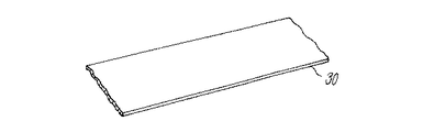
この画像形成装置の梱包に際しては、感光体1と転写ベルト2との間に、図1、図2に示すような弾力性のあるシート30が挾持される。シート30は、発泡ポリエチレン、発泡PURなどにより形成される。
【0016】
なお、ここでは、像担持体として感光体1を用いたが、中間転写ドラムやベルトであっても良い。さらに、転写装置10を接離させる揺動手段11をカム12により構成したがソレノイド等でも良い。
【0017】
図3に示すように、転写ベルト2に代えて、感光体1に対して接離可能な転写ローラ2Aを用いた画像形成装置でも、装置の梱包に際しては、感光体1と転写ローラ2Aとの間にシート30が挾持される。
【0018】
図4に本発明の画像形成装置の梱包方法を実施するための例を示す。以下図1〜図3に示した例に用いた部材と同一部材には同一符号を付し、個々の説明を省略する。
転写ベルト2を支持する支持部材としての転写ベルトフレーム6と、画像形成装置の不動部材としての転写ベルトケース7とには、それぞれ孔6a、7aが設けられている。転写ベルト2は、加圧アーム14Aの回動により、図示しない感光体に接離される。
【0019】
画像形成装置の梱包に際しては、これら孔6a、7aに固定部材としてのピン8を挿入して転写ベルト2を転写ベルトケース7に固定する。なお、本例では、不動部材として転写ベルトケース7を用いが、装置の筐体、感光体1を保持する保持手段などに孔を設けてピンを挿入して、転写装置11を固定しても良い。
【0020】
【発明の効果】
本発明によれば、画像形成装置の梱包時に、転写装置が画像形成装置の不動部材に固定される。よって、画像形成装置の搬送時の振動や衝撃によっても、像担持体と転写装置とが接触しないので、両者に傷が付かず、それらの支持部材の破損を防止できる。
【図面の簡単な説明】
【図1】本発明の画像形成装置の梱包方法を説明する図である。
【図2】像担持体と転写装置との間に挿入するシートを示す斜視図である。
【図3】画像形成装置の別の例を説明する図である。
【図4】本発明の画像形成装置の梱包方法を説明する図である。
【符号の説明】
1 像担持体としての感光体
2 転写ベルト
6 転写ベルトフレーム
7 転写ベルトケース
8 固定部材としてのピン
10 転写装置[0001]
[Industrial application fields]
The present invention relates to a packaging method for an image forming apparatus.
[0002]
[Prior art]
2. Description of the Related Art Image forming apparatuses having a transfer device configured to be able to come into contact with and separate from an image carrier are well known. As a transfer device capable of coming into contact with and separating from the image carrier, there are a belt shape and a roller shape. Such a transfer device is swung to a position separated from the image carrier by a rocking means such as a cam when the image forming apparatus is stopped, and is swung to a position in contact with the image carrier at the time of transfer.
[0003]
This image forming apparatus is placed in a polystyrene foam mold and further packed in a cardboard box.
[0004]
[Problems to be solved by the invention]
In the above-described packing method, the movement of the transfer device relative to the image carrier is not regulated. Therefore, when vibration or impact is applied to the image forming apparatus, the transfer device collides with the image carrier, and the transfer device and the image carrier There is a problem that the both are scratched or the support member that supports both is damaged.
[0005]
An object of the present invention is to provide a method for packing an image forming apparatus in which an image carrier and a transfer device are not damaged and the support members can be prevented from being damaged.
[0006]
[Means for Solving the Problems]
According to a first aspect of the present invention, there is provided a method of packing an image forming apparatus, comprising: an image carrier; and a transfer device that can contact and separate from the image carrier and transfers an image on the image carrier to transfer paper. A hole is provided in each of a support member that supports the transfer device and an immovable member of the image forming apparatus, and when the image forming apparatus is packed, a fixing member is inserted into the holes to attach the transfer device to the immovable member. It is characterized by being fixed to.
[0007]
The invention described in
[0008]
[Action]
According to the present invention, the transfer device is fixed to the immovable member of the image forming apparatus, and the image carrier and the transfer device do not come into contact with each other due to vibration or impact during transportation of the device.
[0009]
【Example】
Hereinafter, an example of an image forming apparatus for specifically carrying out the packing method of the present invention will be described with reference to the drawings.
In FIG. 1, reference numeral 1 denotes a photoconductor as an image carrier. Around the photoreceptor 1, a
[0010]
A transfer device 10 is disposed below the photoreceptor 1. The transfer device 10 is mainly composed of a
[0011]
A bias roller 5 for applying a bias voltage is disposed in contact with the inner peripheral surface of the
[0012]
The oscillating
[0013]
The
[0014]
In the above configuration, a toner image is formed on the photoreceptor 1 by a known image forming unit such as a charger, an exposure unit, and a developing device prior to the transfer operation. The toner image on the photoreceptor 1 is transferred onto the transfer paper 23 conveyed from the
[0015]
When the image forming apparatus is packed, an
[0016]
Here, the photosensitive member 1 is used as the image carrier, but an intermediate transfer drum or a belt may be used. Further, the swinging means 11 for contacting and separating the transfer device 10 is constituted by the
[0017]
As shown in FIG. 3, even in an image forming apparatus using a
[0018]
FIG. 4 shows an example for carrying out the packaging method of the image forming apparatus of the present invention. In the following, the same members as those used in the examples shown in FIGS.
The
[0019]
When packing the image forming apparatus, the
[0020]
【The invention's effect】
According to the present invention, the transfer device is fixed to the immovable member of the image forming apparatus when the image forming apparatus is packed. Therefore, the image carrier and the transfer device do not come into contact with each other even when the image forming apparatus is transported or shocked, so that both of them are not damaged and the support members can be prevented from being damaged.
[Brief description of the drawings]
FIG. 1 is a diagram illustrating a method for packing an image forming apparatus according to the present invention.
FIG. 2 is a perspective view showing a sheet inserted between an image carrier and a transfer device.
FIG. 3 is a diagram illustrating another example of an image forming apparatus.
FIG. 4 is a diagram illustrating a method for packing an image forming apparatus according to the present invention.
[Explanation of symbols]
DESCRIPTION OF SYMBOLS 1 Photoconductor as
Claims (2)
上記転写装置を支持する支持部材と、画像形成装置の不動部材とに孔をそれぞれ設け、画像形成装置の梱包時に、これら孔に固定部材を挿入して上記転写装置を上記不動部材に固定することを特徴とする画像形成装置の梱包方法。 A hole is provided in each of the support member that supports the transfer device and the immovable member of the image forming apparatus, and when the image forming apparatus is packed, a fixing member is inserted into these holes to fix the transfer device to the immovable member. A method for packing an image forming apparatus.
Priority Applications (1)
| Application Number | Priority Date | Filing Date | Title |
|---|---|---|---|
| JP24438394A JP3609461B2 (en) | 1994-10-07 | 1994-10-07 | Packaging method for image forming apparatus |
Applications Claiming Priority (1)
| Application Number | Priority Date | Filing Date | Title |
|---|---|---|---|
| JP24438394A JP3609461B2 (en) | 1994-10-07 | 1994-10-07 | Packaging method for image forming apparatus |
Publications (2)
| Publication Number | Publication Date |
|---|---|
| JPH08113282A JPH08113282A (en) | 1996-05-07 |
| JP3609461B2 true JP3609461B2 (en) | 2005-01-12 |
Family
ID=17117872
Family Applications (1)
| Application Number | Title | Priority Date | Filing Date |
|---|---|---|---|
| JP24438394A Expired - Fee Related JP3609461B2 (en) | 1994-10-07 | 1994-10-07 | Packaging method for image forming apparatus |
Country Status (1)
| Country | Link |
|---|---|
| JP (1) | JP3609461B2 (en) |
Families Citing this family (4)
| Publication number | Priority date | Publication date | Assignee | Title |
|---|---|---|---|---|
| JPH1115292A (en) * | 1997-06-20 | 1999-01-22 | Ricoh Co Ltd | Image forming device |
| JPH10186889A (en) * | 1996-11-01 | 1998-07-14 | Ricoh Co Ltd | Image forming device |
| JP2006350119A (en) * | 2005-06-17 | 2006-12-28 | Ricoh Co Ltd | Image forming apparatus |
| JP6056217B2 (en) * | 2012-06-29 | 2017-01-11 | ブラザー工業株式会社 | Image forming apparatus |
-
1994
- 1994-10-07 JP JP24438394A patent/JP3609461B2/en not_active Expired - Fee Related
Also Published As
| Publication number | Publication date |
|---|---|
| JPH08113282A (en) | 1996-05-07 |
Similar Documents
| Publication | Publication Date | Title |
|---|---|---|
| US7272339B2 (en) | Process cartridge including first and second frames and separating member moving the second frame to a separated position and image forming apparatus detachably mounting the cartridge | |
| US3888577A (en) | Apparatus for packaging and subsequently installing a belt onto a roller assembly | |
| JP2750009B2 (en) | Image forming device | |
| JP3609461B2 (en) | Packaging method for image forming apparatus | |
| JP4092191B2 (en) | Bag materials, packing materials, and image forming unit packages | |
| US5357328A (en) | Ground strip brush cleaner | |
| JPH04138484A (en) | Image forming device | |
| EP0037248A2 (en) | Method and device for recycling developing material | |
| JPH11133730A (en) | Image forming device | |
| JPH09152826A (en) | Printer | |
| JP3567983B2 (en) | Image forming machine | |
| JP3382431B2 (en) | Electrophotographic equipment | |
| JP2002132042A (en) | Image forming machine | |
| JP2001272868A (en) | Image forming apparatus and transferring device | |
| JP4291063B2 (en) | Image forming apparatus | |
| JPH05158387A (en) | Image forming device | |
| JP2002006644A (en) | Transfer device and image forming device having the same | |
| JP3003085B2 (en) | Transfer paper separation device | |
| JPH06242661A (en) | Corona discharging device | |
| JP3306225B2 (en) | Paper transport device | |
| JPH112936A (en) | Electrophotographic device | |
| JPH03101777A (en) | Image forming device | |
| JPH03249781A (en) | Developer leakage preventing device and process cartridge provided therewith | |
| CN115729076A (en) | Image forming apparatus with a toner supply device | |
| JP3235046B2 (en) | Process unit |
Legal Events
| Date | Code | Title | Description |
|---|---|---|---|
| A977 | Report on retrieval |
Free format text: JAPANESE INTERMEDIATE CODE: A971007 Effective date: 20040331 |
|
| A131 | Notification of reasons for refusal |
Free format text: JAPANESE INTERMEDIATE CODE: A131 Effective date: 20040427 |
|
| A521 | Written amendment |
Free format text: JAPANESE INTERMEDIATE CODE: A523 Effective date: 20040610 |
|
| TRDD | Decision of grant or rejection written | ||
| A01 | Written decision to grant a patent or to grant a registration (utility model) |
Free format text: JAPANESE INTERMEDIATE CODE: A01 Effective date: 20041012 |
|
| A61 | First payment of annual fees (during grant procedure) |
Free format text: JAPANESE INTERMEDIATE CODE: A61 Effective date: 20041014 |
|
| R150 | Certificate of patent or registration of utility model |
Free format text: JAPANESE INTERMEDIATE CODE: R150 |
|
| FPAY | Renewal fee payment (event date is renewal date of database) |
Free format text: PAYMENT UNTIL: 20071022 Year of fee payment: 3 |
|
| FPAY | Renewal fee payment (event date is renewal date of database) |
Free format text: PAYMENT UNTIL: 20081022 Year of fee payment: 4 |
|
| FPAY | Renewal fee payment (event date is renewal date of database) |
Free format text: PAYMENT UNTIL: 20081022 Year of fee payment: 4 |
|
| FPAY | Renewal fee payment (event date is renewal date of database) |
Free format text: PAYMENT UNTIL: 20091022 Year of fee payment: 5 |
|
| FPAY | Renewal fee payment (event date is renewal date of database) |
Free format text: PAYMENT UNTIL: 20101022 Year of fee payment: 6 |
|
| FPAY | Renewal fee payment (event date is renewal date of database) |
Free format text: PAYMENT UNTIL: 20111022 Year of fee payment: 7 |
|
| FPAY | Renewal fee payment (event date is renewal date of database) |
Free format text: PAYMENT UNTIL: 20121022 Year of fee payment: 8 |
|
| FPAY | Renewal fee payment (event date is renewal date of database) |
Free format text: PAYMENT UNTIL: 20131022 Year of fee payment: 9 |
|
| LAPS | Cancellation because of no payment of annual fees |