JP3607253B2 - Spinning wheel management system - Google Patents
Spinning wheel management system Download PDFInfo
- Publication number
- JP3607253B2 JP3607253B2 JP2002057380A JP2002057380A JP3607253B2 JP 3607253 B2 JP3607253 B2 JP 3607253B2 JP 2002057380 A JP2002057380 A JP 2002057380A JP 2002057380 A JP2002057380 A JP 2002057380A JP 3607253 B2 JP3607253 B2 JP 3607253B2
- Authority
- JP
- Japan
- Prior art keywords
- sushi
- management system
- food
- dishes
- type
- Prior art date
- Legal status (The legal status is an assumption and is not a legal conclusion. Google has not performed a legal analysis and makes no representation as to the accuracy of the status listed.)
- Expired - Lifetime
Links
- 238000009987 spinning Methods 0.000 title 1
- 238000007726 management method Methods 0.000 claims description 54
- 235000013305 food Nutrition 0.000 claims description 17
- 238000001514 detection method Methods 0.000 claims description 6
- 238000012545 processing Methods 0.000 description 27
- 238000010586 diagram Methods 0.000 description 17
- 238000000034 method Methods 0.000 description 17
- 230000008569 process Effects 0.000 description 15
- 230000008859 change Effects 0.000 description 5
- 230000003287 optical effect Effects 0.000 description 5
- 230000010355 oscillation Effects 0.000 description 5
- 230000000694 effects Effects 0.000 description 4
- 239000000463 material Substances 0.000 description 4
- 238000004364 calculation method Methods 0.000 description 3
- 238000004891 communication Methods 0.000 description 3
- 238000010411 cooking Methods 0.000 description 3
- 238000007599 discharging Methods 0.000 description 3
- 239000002699 waste material Substances 0.000 description 3
- 241000972773 Aulopiformes Species 0.000 description 2
- 238000012937 correction Methods 0.000 description 2
- 239000002994 raw material Substances 0.000 description 2
- 230000009467 reduction Effects 0.000 description 2
- 235000019515 salmon Nutrition 0.000 description 2
- 239000010802 sludge Substances 0.000 description 2
- 241000238366 Cephalopoda Species 0.000 description 1
- 241000238557 Decapoda Species 0.000 description 1
- 238000007796 conventional method Methods 0.000 description 1
- 235000021185 dessert Nutrition 0.000 description 1
- 230000006866 deterioration Effects 0.000 description 1
- 230000008030 elimination Effects 0.000 description 1
- 238000003379 elimination reaction Methods 0.000 description 1
- 238000005516 engineering process Methods 0.000 description 1
- 230000007717 exclusion Effects 0.000 description 1
- 238000007689 inspection Methods 0.000 description 1
- 238000009434 installation Methods 0.000 description 1
- 238000012423 maintenance Methods 0.000 description 1
- 238000004519 manufacturing process Methods 0.000 description 1
- 238000012986 modification Methods 0.000 description 1
- 230000004048 modification Effects 0.000 description 1
- 235000011962 puddings Nutrition 0.000 description 1
- 239000004065 semiconductor Substances 0.000 description 1
- 230000003442 weekly effect Effects 0.000 description 1
Images


Landscapes
- Table Equipment (AREA)
- Management, Administration, Business Operations System, And Electronic Commerce (AREA)
Description
【0001】
【発明の属する技術分野】
この発明は回転ずし管理システムに関し、特にコンベアにより配送されるすしの廃棄の管理を行なう回転ずし管理システムに関する。
【0002】
【従来の技術】
従来より、複数の回転ずし店舗を管理、運営する企業が知られている。各店舗においては、回転ずしコンベアを有する回転テーブルが備えられ、すしなどの食品はコンベアにより搬送されながら顧客に提供される。
【0003】
また、皿に印を付与することで皿を管理し、所定時間が経過した皿は排除することなどが行なわれている。
【0004】
【発明が解決しようとする課題】
ところで、コンベアのスピードなどが変化することに伴い、すしなどの食品にあたる風の速さが変化することがある。このように風の速さなどが変化すると、商品の劣化までの時間も変化するが、従来の技術においては、このような変化に対応できないという問題があった。
【0005】
この発明はそのような問題点を解決するためになされたものであり、環境が変化しても商品を適切に管理することができる回転ずし管理システムを提供することを目的としている。
【0006】
【課題を解決するための手段】
上記目的を達成するためこの発明のある局面に従うと、回転ずし管理システムは、コンベアにより配送される食品の管理を行なう回転ずし管理システムであって、食品は皿に載せられており、皿の各々には、皿の各々を他の皿から識別するための情報が付与されており、皿の各々を他の皿から識別するための情報を読取る読取手段と、皿の各々が配送された距離を判定する判定手段と、読取手段の読取結果と前記判定手段の判定結果とに基づいて、前記食品を廃棄する廃棄手段とを備える。
【0007】
好ましくは回転ずし管理システムは、食品の種類ごとに、当該食品を廃棄するまでの配送距離を記憶する距離記憶手段をさらに備え、廃棄手段は、判定手段の判定結果と、距離記憶手段の記憶内容とに基づいて廃棄を行なう。
【0008】
好ましくは回転ずし管理システムは、パラメータに基づいて、食品を廃棄するまでの配送距離を食品の種類ごとに決定する決定手段をさらに備える。
【0009】
好ましくは回転ずし管理システムは、食品とともに配送される識別子を検出する検出手段と、検出手段により検出された識別子に基づき、皿の各々に載せられたすしの種類を判定する判定手段と、皿の各々を識別するための情報に対応させて、判定手段の判定結果を記憶する結果記憶手段とをさらに備える。
【0010】
好ましくは識別子には、その後に続いて配送されるすしの種類を示す情報が記載されている。
【0011】
【発明の実施の形態】
図1は、本発明の実施の形態の一つにおける回転ずし店舗運営システムの構成を示す図である。
【0012】
図を参照して、回転ずし店舗運営システムは、各店舗における商品の発注、売上、勤怠その他の各種情報を管理する本部100と、顧客にすしを提供する複数の店舗200a〜200dと、すしの原材料の加工を行なう調理センター300と、すしの原材料の仕入先400a,400bとから構成されている。
【0013】
本部100と、各店舗200a〜200d、調理センター300、および仕入先400a,400bとは通信回線(これには公衆回線、専用線、インターネットなどを用いることができる)で相互に接続されている。
【0014】
また、本部100はインターネット500に接続されている。
各店舗200a〜200dには、来店した客の人数、客層を入力するための端末や、コンベア上に存在するすしの種類および量などを検出するセンサが備えられている。これらの端末やセンサにより得られた情報は、リアルタイムで本部100に送られる。これにより、本部100では各店舗の状況をリアルタイムに把握することができる。
【0015】
また、各店舗において、1日のうちに提供されたすしの総数がその種類ごとにカウントされ、そのカウントされた量に基づいて仕入先400a,400bへ、電話、ファクシミリ、電子メールなどの通信手段を用いて自動的に発注が行なわれる。
【0016】
なお、各店舗のコンベア上を所定距離搬送されたすしは、排出装置(これはコンピュータからの信号に基づいて動作するアクチュエータなどにより構成される)により自動的に廃棄されるが、この廃棄されたすしの量も自動的にカウントされ、発注量(仕入量)を決定するときに考慮される。
【0017】
これにより、たとえば人気がなく破棄された量が多かった種類のすしの材料は、発注量を減らし、かつその店舗における供給量を少なくすることができる。
【0018】
図2は、本実施の形態における回転ずし店舗運営システムの構成を示す図である。
【0019】
図を参照して、回転ずし店舗運営システムは、すし供給システム600と、店舗管理システム700と、全社経営システム800とから構成される。
【0020】
すし供給システム600は、各店舗において、商品や顧客の各情報をリアルタイムに収集し、店舗運営に必要な各種情報を提供するシステムである。すし供給システムとして特願平9−268640号および特願平10−312237号に開示された技術を用いることができる。
【0021】
店舗管理システム700は、各店舗における、商品発注、売上、勤怠などの各種情報を集中管理し、各店舗の運営を容易かつ均一に管理するシステムである。
【0022】
全社経営システム800は、各店舗の毎日の営業情報の収集把握と、会社内で発生する各種情報とを集中管理し、リアルタイムに経営状況を把握するためのシステムである。また、会社経営システム800は、結果的に集約された情報を処理することにより得られる、財務情報および経理情報を管理する。
【0023】
すし供給システム600は各店舗200a〜200dに設置され、店舗管理システム700および全社経営システム800は本部100に設置される。
【0024】
以下、各システムの詳しい内容について説明する。
(1) すし供給システム600
すし供給システム600は、客席に供給するすしのねたの組合せおよび数量の最適値を指示することを目的とするシステムである。また、すし供給システム600はすしの供給後所定距離の搬送が行なわれたすしを、回転テーブルから自動的に排除することも目的としている。
【0025】
すし供給システム600によって以下の効果が導かれる。
(a) 客の嗜好に合ったすしの供給
(b) 衛生管理を重視したすしの供給と排除
(c) 店舗従業員の負担軽減
(d) 端末を用いて従業員が客の人数や年齢層などを入力することによる客層の把握
(e) 売れ筋すしの計数および自動把握
(f) ロスの軽減
(g) 材料の自動発注
(h) 店舗情報の自動収集(供給すし総数、ねた種類、ねた別個数、廃棄数、廃棄種類、入場総人員、客組数、1組当たりの客数、大人/子供別人数、客単価など)
なお、すし供給システム600はハードウェア構成として、店舗内パーソナルコンピュータ(PC)−ローカルエリアネットワーク(LAN)システム、CCDカラーカメラ、各種センサ類から構成される。
【0026】
(2) 店舗管理システム700
店舗管理システム700は、各店舗から送られてきた各種情報およびデータをオンラインにより収集し、処理の自動化、迅速化および簡素化を図ることを目的としている。また、あらゆる業務のコンピュータ化を図ることで、将来店舗数が増えたときなどにおいても対応がしやすくなる。また、コンピュータ化により経費削減および経営の合理化を図ることができる。
【0027】
また店舗管理システム700により、現場および本社の処理の自動化を図ることができる。
【0028】
店舗管理システム700は、以下のように構成される。
すなわち、各店舗にすし供給システム600およびデータ入力用専用端末が設置され、公衆回線などの回線により、すし供給システム600および各端末が本部100のPC−LANと接続される。
【0029】
各店舗から専用端末を用いて、発注、検収、棚卸し、売上、現金、勤怠、経費などの各データが入力され、店舗管理システム700に送信される。また各店舗から客層、廃棄数、供給数などのすし供給システム600のデータが店舗管理システム700へ送信される。
【0030】
店舗管理システム700においては受信データを分類し、受信データの種類により各種処理(受注処理、発注処理、買掛け処理、棚卸し処理、売上処理、現金有高処理など)が行なわれる。
【0031】
(3) 会社経営システム800
全社経営システム800は、小さな本社、迅速な経営判断および正確、迅速な経営状況の把握を目的として導入されるシステムである。
【0032】
全社経営システム800を導入することにより、経営合理化、経費削減、情報の共有および経営の透明化という効果が達成される。
【0033】
全社経営システム800は以下の作業を行なう。
(a) 本部のPC−LANシステムによる、各データの自動処理
(b) 給与計算処理
(c) 経理処理
(d) 月次決算
(e) 日次、月次利益管理
(f) 日次、週間、月次店舗管理
(g) 原価管理
図3は、図1の各店舗200a〜200dに設けられるすし供給システムの具体的な構成を示す図である。
【0034】
図を参照して、すし供給システムは、店舗端末201と、客層入力端末203と、回転テーブル205a,205bと、回転テーブル上を移動するすしの通過などを検出するセンサ207a〜207nと、所定距離搬送されたすしを排出する排出装置209a,209bと、移動するすしを上から写すCCDカメラ211a,211bと、顧客などに対し広告などの情報を表示する表示モニタ231と、厨房内の従業員に対し作るべきすしの種類および量を指示するための指示モニタ213a,213bと、画像処理や表示処理を行なうための画像用パーソナルコンピュータ215a,215bと、信号の切換を行なう切換ボックス217と、システム全体の制御を行なう制御ボックス219と、複数のコンピュータを接続するためのハブ221と、回転テーブル上のすしの追跡処理を行なうトラッキングパーソナルコンピュータ223と、データの蓄積を行なうサーバパーソナルコンピュータ225と、データを出力するためのプリンタ229と、公衆回線と接続するためのモデム227とから構成される。
【0035】
店舗端末201は公衆回線250に接続される。
調理から一定距離を搬送されたすしは排出装置209a,209bにより廃棄される。このとき、廃棄されたすしの種類および数量がカウントされ、サーバPC225に入力される。
【0036】
客層入力端末203により入力された客の数および客の種類(大人であるか子供であるか)に基づき、回転テーブル205a,205bに出ている現在のすしの種類と数量を考慮し、トラッキングPC223は回転テーブル205a,205b上のすしの適切な種類と適量とを求め、それに適合するように指示モニタ213a,213bにすし調理の指示(種類と数量)を表示する。このようにして各店舗において、顧客のニーズに合った種類、およびニーズに合った量のすしの提供を、従業員の勘などに頼ることなく行なうことができる。
【0037】
図4は、図1の本部100と調理センター300と各仕入先400a,400bとに備えられるシステムの構成を示す図である。この図における本部内のシステムが、図2の店舗管理システム700および全社経営システム800のハードウェアに相当する。
【0038】
本部のシステムは、公衆回線250に接続される複数のモデム101と、サーバ103,105と、パーソナルコンピュータ107a〜107hと、プリンタ109a,109bと、モデム111とから構成される。
【0039】
調理センターのシステムはパーソナルコンピュータ301と、プリンタ303とから構成される。
【0040】
仕入先のシステムはファクシミリ装置401とパーソナルコンピュータ403とから構成される。
【0041】
本部および調理センターの各種装置はLANにより接続される。また、本部と仕入先のシステムとは公衆回線250を介して接続される。
【0042】
また、本部のシステムはインターネット500に接続される。これにより、一般の顧客はインターネット500を介して本部のシステムにアクセスし、サーバ103,105に蓄積されたデータ(回転ずし店舗の広告データやアンケートなどのデータ)にアクセスすることができるし、インターネット500を介して一般顧客がすしの注文を行なうこともできる。
【0043】
図5は、各店舗におけるすし供給システムで1日の営業終了後に行なわれる処理を示すフローチャートである。
【0044】
図を参照して、ステップS101において、その1日のうちに提供されたすしの量を種類別にカウントする。次に、ステップS103で廃棄されたすしの量を種類別にカウントする。
【0045】
ステップS105において、提供された量および廃棄された量に基づき材料の発注量が自動的に計算される。
【0046】
ステップS107においてカレンダー、天候、その他の特殊事情を考慮して発注量の調整が行なわれる。
【0047】
ステップS109において回線を通じて自動的に発注が行なわれる。
このように本システムにおいては各店舗におけるすしの提供量、廃棄量およびカレンダー、天候その他の事情を考慮して適切な発注量の計算および自動発注を行なうことができる。また、すし供給システムにより客層に応じた好ましい量のすしを適切な量だけ回転テーブルに提供することができる。
【0048】
さらに、各店舗における各種情報を本部で集中的に管理することができる。
これによりたとえば各店舗における従業員は、すしの提供や仕入に関する専門知識やノウハウを知らなくても店舗を運営することができる。これにより、本システムの導入により回転ずし店舗を簡易かつ合理的に運営することが可能になるという効果を奏する。
【0049】
図6は、図1の回転ずし店舗運営システムに含まれる、すし数量カウント装置の構成を示すブロック図である。
【0050】
図を参照して、すし数量カウント装置は、装置全体の制御を行なうCPU601と、以下に述べるフローチャートに示されるプログラムなどを記憶するROM611と、すしの数量を種類ごとに記録するRAM613と、回転テーブル付近に設けられるセンサ207と、従業員に対しすし調理の指示を与えたりすしの数量の表示を行なうディスプレイ装置213と、外部記憶装置609とから構成される。
【0051】
なおセンサ207は、図3のセンサ207a〜207nの1つを代表して表わしたものであり、ディスプレイ装置213は図3の指示モニタ213a,213bのいずれかを代表して表わしたものである。
【0052】
センサ207には、回転テーブルにより搬送されるメニュー立てから出力される電波を検出する電波センサ603と、すし皿の通過を検出する光センサ605とが含まれている。
【0053】
図7は、センサ207の設置例を示す側面図である。図を参照して、センサ207は、回転テーブル205の近くに設けられる。すしが載せられた皿Pが光センサ605の前を通りすぎるときに、皿Pが光センサ605に入射される光を遮る。これにより、1枚の皿の通過が検出される。また、光が遮られた回数を測定することで、通過するすし皿の数量をカウントすることができる。
【0054】
図8は、メニュー立ての構成を示す斜視図である。メニュー立てには、人間が目視できるようにすしの種類を示す文字や図形(または写真など)が書かれている。また、メニュー立てには発振回路部分651(識別子の一種)が設けられている。
【0055】
発振回路部分651は、そのメニュー立てに特有の信号(たとえば「0001」、「0002」などのセンサ番号)を出力する。メニュー立てもすし皿とともに回転テーブル205により配送される。センサ207に設けられた電波センサ603(図7参照)の前をメニュー立てが通過するときに、発振回路部分651から出力された信号を電波センサ603がキャッチする。これにより、どの種類のメニュー立てがセンサ207の部分を通過したかが判定される。
【0056】
回転テーブル205上には複数のメニュー立てを載置しておき、メニュー立てとメニュー立てとの間からなる領域に、メニュー立てに記載された種類のすしが載せられた皿を置いておく。メニュー立ての発振回路部分651が出力する信号をすしの種類に対応させておくことで、その種類のすしが何個回転テーブル205上に存在するかを光センサ605によりカウントすることができる。これにより、回転テーブル205上にあるすしの数量をその種類ごとにリアルタイムに把握することが可能である。
【0057】
より詳しい具体例を以下に説明する。
図9は、回転テーブル205を模式的に上から見た状態を示す図である。すし皿P1〜P7およびメニュー立てS1〜S5は、白矢印で示されるように回転テーブル205の上を反時計回りに回転しているものとする。このとき、各々のメニュー立てを先頭として、次のメニュー立てまでの間が1つの領域を構成する。図9においては、メニュー立てS1により領域A1が構成され、メニュー立てS2により領域A2が構成される。同様に、メニュー立てS3〜S5のそれぞれにより、領域A3〜A5が構成される。
【0058】
たとえば、図8のようにメニュー立てS1に「マグロ」を示す文字、図形、写真などが記載されており、そのメニュー立てに設けられた発振回路部分651がセンサ番号「0001」を示す信号を出力するものとする。このとき、メニュー立てS1により作られる空間A1内にマグロのすしが載せられた皿P1,P2を載せておくことで、センサ207を用いて、マグロのすしの皿の数(ここでは皿P1,P2の2枚)をカウントすることができる。
【0059】
より具体的には、センサ207がメニュー立てS1の通過を検出すると、カウンタが皿の数のカウントを開始し、その後センサ207によりメニュー立てS2の通過が検出されるまで皿の数のカウントが行なわれる。
【0060】
図10は、図6のRAMに記録されるテーブルを示す図である。センサ番号0001,0002,0004をそれぞれマグロ、イカ、サーモンに対応させておき、センサを用いることでそれらの種類のすしがテーブル上に何個あるかがリアルタイムに把握される。
【0061】
図11は、当該すし数量カウント装置を用いて従業員に指示を出す処理を示すフローチャートである。
【0062】
このフローチャートは図6のCPU601などにより実行される。まず、ステップS201で初期化が行なわれる。
【0063】
ステップS203において客層入力端末203などを用いて客層およびその人数などが入力される。ステップS205において、客層やその人数などに基づき現在の回転テーブル上に必要なすしの種類と量とを算出する。この算出は数式などに基づいて行なうようにしてもよいし、テーブルを用いて求めるようにしてもよい。
【0064】
ステップS207において、すし数量カウント装置により現在の回転テーブル上のすしの量を種類ごとに把握する。
【0065】
ステップS209において、把握されたすしの種類および量と、必要なすしの種類と量とに基づいて、作るべきすしの種類と量とを算出し、ステップS211においてディスプレイ装置213を用いて従業員に指示を行なう。
【0066】
ステップS213において、店の業務が終了するまでステップS203からの処理を繰返し行なう。
【0067】
図12は、すし皿のカウント処理を示すフローチャートである。
図を参照して、ステップS301においてセンサにより検出処理が行なわれる。ステップS303でメニュー立てがセンサの前を通過したかが判定され、NOであれば、ステップS305ですし皿が通過したかが判定される。
【0068】
ステップS305でYESであれば、ステップS307で現在のメニュー立てに対応したカウンタを1増やす処理が行なわれ、ステップS301へ戻る。
【0069】
また、ステップS305ですし皿の通過が検出されない場合には、ステップS301へ戻る。
【0070】
ステップS303でYESであれば、ステップS309でメニュー立て変更処理が行なわれる。
【0071】
図13は、図12のメニュー立て変更処理(S309)の内容を示すフローチャートである。
【0072】
図を参照して、ステップS401においてメニュー立てに対応したカウンタのカウント値を確定する。そして、以前にそのメニュー立てに対応したカウンタのカウント値を保存しておいたスタックからデータを読出し、その差分を求め、ディスプレイ装置213に表示する。
【0073】
ステップS403において現在のメニュー立てに対応したカウンタをスタックに退避し、ステップS405で現在のメニュー立てに対応したカウンタをクリアして、メインルーチンに戻る。
【0074】
以上のように、本実施の形態においてはメニュー立てと皿とを検出することにより、すしの数量をその種類ごとに容易にカウントすることができ、カウントされたすしの数量に基づき従業員に対するすし作製の指示や、材料の発注などを容易に行なうことができるという効果がある。
【0075】
なお、本実施の形態においてはすしの種類を検出する方法としてメニュー立てを用いたが、すしの種類を識別できる情報(たとえばバーコードなどのマーク、色、模様、信号など)を外部に示すことができるものであればメニュー立ての代わりに用いることができる。
【0076】
図14は、回転ずし店舗運営システムにおいて使用されるすし皿の底面図である。すし皿の各々に、各々の皿を識別するための識別子653(1次元、2次元バーコードや半導体チップなどの情報を保持するもの)が付されている。識別子653の情報は図7に示されるセンサSEにより読取られる。
【0077】
このような各々の皿を識別するための識別子653を用いることで、すし皿の1枚1枚にIDを割り振ることができる。そして、メニュー立てなどを用いて皿に載せられたすしの種類を特定することで、どのすし皿にどの種類のすしが載っているかを個別に管理することが可能となる。
【0078】
また、皿の各々がどの位置にあるかを座標などにより管理することも可能である。
【0079】
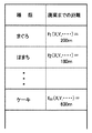
図15は、RAM613に記録される、商品ごとの廃棄までの距離テーブルを示す図である。
【0080】
図に示されるように、本実施の形態においては、商品の種類ごとに、その商品が廃棄されるまでの移動距離が記録される。なお、当該距離は、商品ごとに固定の数値としてもよいが、本実施の形態においては商品ごとに関数f1、f2、・・・を記憶させ、店舗内の温度、湿度、回転テーブル上における商品の移動速度(または商品にあたる風の風速)などのパラメータx、y、・・・に基づき各々の商品での距離を演算するようにしている。
【0081】
すなわち、図15の例では、店舗内の温度、湿度などに基づく計算により、マグロでは廃棄までの距離が200mとされ、ハマチでは180mとされ、ケーキでは600mと演算されているが、温度などの条件が変わることで、これらの距離は変化する。
【0082】
なお、温度などのパラメータは温度センサなどでシステムに入力することが望ましいが、キーボードなどから人為的に入力するようにしてもよい。また、インターネットなどから入力を行なうようにしてもよい。本実施の形態によると、パラメータに基づいて、図15に示されるテーブルが自動的に更新されるため、ユーザの設定の労力を軽減させることが可能となる。
【0083】
従来のシステムとして、単純に商品投入からの時間や、商品の回転テーブルにおける周回回数などを測定し、所定の時間や周回回数が経過すると、商品の廃棄を行なうものがあった。しかしながら、現実的には空調の状態、季節、商品の移動速度、商品が一周するまでの距離により商品劣化までの時間や周回回数は異なってくる。これにより、システムのメンテナンスにあたって、時間や周回回数を頻繁に設定する必要があるが、従来のシステムにおいては、手作業で設定が行なわれていたため、面倒であるという問題点があった。
【0084】
また、すべての商品について単純に、回転テーブルを5周したら廃棄、などと設定するのであれば、設定におけるユーザの労力も少なくてよいが、本実施の形態では、商品の種類ごとに廃棄までの距離を変えているため、もしも従来のようなシステムのメンテナンスをするのであれば、すべての商品について設定を行なわなければならない。本実施の形態では、パラメータに基づく自動設定を行うことで、そのような労力を軽減することができる。
【0085】
図16は、本実施の形態においてRAM613に記録されるテーブルを示す図である。図に示されるように、すし皿のIDごとに、そのすし皿に載せられているすしの種類が記録される。また、そのすし皿がセンサSEで最初に検出されてからの移動距離(これはすしが作られてからの移動距離を示す)が記録される。これにより、作られてから所定の距離(図15のテーブルで示される距離)を移動したすしなどを廃棄することが可能となる。
【0086】
また、本実施の形態では、すし皿に乗っている商品の種類(マグロ、サーモン、エビなどのすしの種類や、ケーキ、プリンなどのデザートの種類)に応じて、商品を廃棄するまでの距離を変更しているので、商品の鮮度管理をより適切に行なうことができる。
【0087】
従来の技術においてはコンベアにより搬送される商品を個別に管理できないという問題があった。たとえば、すしを乗せた皿とケーキを載せた皿とがコンベア上にある場合を想定する。このとき、鮮度が低下するまでの移動距離はすしの方が短いため、すしの皿を排除するまでの移動距離をケーキの皿の移動距離よりも短くすることが望まれる。しかしながら、従来の技術においては、皿上の商品を特定することができなかった。そのため、商品ごとに排除までの距離を特定することができなかったのである。
【0088】
しかしながら本実施の形態によると、皿に載せられた商品の種類を特定することができるため、商品に合致させた廃棄までの距離を設定することができるのである。
【0089】
また、すし皿がセンサSEにより所定時間検出されなくなったときには、そのすしが消費されたものと考えることができる。さらに、長期(数日のオーダなど)にわたり、検出されなかったIDのすし皿は、破損または紛失したものとみなして処理することができる。
【0090】
図16において、移動距離が廃棄までの距離を過ぎているすし皿に対しては廃棄フラグが「1」とされ、次にそのすし皿が排出装置209a、209b(図3参照)の位置に来た時に、廃棄が行なわれる。
【0091】
なお、移動距離を図16のテーブルに記録する際には、すし皿を認識するセンサ間の距離に基づいて移動距離を算出するようにしてもよいし、コンベアの移動速度と時間とに基づいて移動距離を演算するようにしてもよい。また、コンベアの速度はセンサなどによる実測値を用いてもよいし、定数としてもよい。
【0092】
また、商品は移動していなくとも劣化が生じるので、それを考慮して補正された移動距離を演算するようにしてもよい。例えば、以下の数式により移動距離Lを求めるようにしてもよい。
【0093】
L=S×T+C×T−a×w
ここにSは、コンベアになにも載っていないときのコンベアの速度(例えば6m/分)であり、Tは、商品が最初にセンサによって認識されてからの時間(すなわち作成からの時間)であり、Cは、商品が停止しているときの劣化の度合いを示すパラメータであり、aは、コンベアに載っている商品の重さの補正を行うための係数であり、wはコンベアに載っている商品の重さである。
【0094】
なお、パラメータである上記C,aは、本部から通信回線で各店舗に送り、自動的にシステムに設定されるようにしてもよい。このようにすると、各店舗ごとに設定を行なう必要がなくなり、調整を行なうときや、新製品が販売されたときなどにおいても簡単な処理で対応を行うことができる。
【0095】
商品がコンベア上に多く載っているほどにコンベアの速度は遅くなるので、aおよびwはそれを補正する。なお、wは、コンベアに設けられたセンサにより測定するように装置を構成することが望ましい。また、コンベア上の皿の総数をカウントし、それに基づいて補正を行うようにしてもよい。
【0096】
なお、コンベアの速度やモータの回転数などをセンサなどにより実測するのであれば、aおよびwによる補正は不要である。
【0097】
また、上記式に、温度、湿度をパラメータとした補正を行うようにしてもよい。
【0098】
図17は、図16のテーブルを記録する処理を示すフローチャートである。
図を参照して、ステップS501においてセンサにより検出処理が行なわれる。ステップS503でメニュー立てがセンサの前を通過したかが判定され、NOであれば、ステップS505ですし皿が通過したかが判定される。
【0099】
ステップS505でYESであれば、ステップS507で現在のメニュー立てに対応した商品の種類を、すし皿IDに対応付けて記録する処理が行なわれ、ステップS509で当該すし皿が最初に認識されてからの移動距離を演算し、テーブルに記録する処理が行なわれる。その後、ステップS501へ戻る。
【0100】
また、ステップS505ですし皿の通過が検出されない場合には、ステップS501へ戻る。
【0101】
ステップS503でYESであれば、ステップS511で現在認識しているメニュー立てを変更する処理が行なわれる。
【0102】
従来はすしの単品の情報(どの種類のすしをどれだけ作ったかなどの情報)をコンピュータに入力することが非常に煩雑であり、すし皿の個別の管理を行なうことが難しいという問題があった。しかしながら、本実施の形態によるとすしに関する情報が皿ごとに自動的に入力されるため、人間の労力を減らすことができ、すし皿ごとの管理を容易に行なうことができるという効果がある。
【0103】
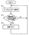
図18は、廃棄フラグをセットする処理を示すフローチャートである。
図を参照して、ステップS12で、図16のテーブルから一つのすし皿に関するデータが取得され、ステップS13で、そのすし皿の移動距離がその商品の廃棄までの距離(図15)よりも長くなっているかが判定され、YESであればステップS14で当該すし皿の廃棄フラグを「1」とする。
【0104】
なお、本実施の形態においては図16に示されるように、商品が最初に認識されてからの移動距離を計測するようにしたが、商品が最初に認識されたときに、その商品の廃棄までの距離をテーブルに記録し、商品の進行に応じてテーブルの距離を減算するようにしてもよい。そして、距離が0以下になった商品は、廃棄フラグが立ったものとみなして扱うようにするのである。このようにすると、廃棄フラグの判定、記録が不要となる。
【0105】
以上のようにシステムが構成されることで、本実施の形態によると、以下の効果がある。まず、時間などではなく、距離により商品を管理するので、コンベアの速度や回転テーブルのレーンの長さが変わるなどの状況の変化があってもそれに対応することができるシステムを構成することができる。
【0106】
また、商品の種類ごとに廃棄までの距離を変更することができるため、商品の性質に応じた鮮度管理をすることができる。さらに商品ごとの廃棄までの距離を状況に応じて容易に変更できるため、ユーザの労力を軽減することができる。
【0107】
今回開示された実施の形態はすべての点で例示であって制限的なものではないと考えられるべきである。本発明の範囲は上記した説明ではなくて特許請求の範囲によって示され、特許請求の範囲と均等の意味および範囲内でのすべての変更が含まれることが意図される。
【図面の簡単な説明】
【図1】本発明の実施の形態の1つにおける回転ずし店舗運営システムの構成を示す図である。
【図2】回転ずし店舗運営システムの構成を示す図である。
【図3】すし供給システムの具体的な構成を示す図である。
【図4】本部と調理センターと各仕入先に備えられるシステムの構成を示す図である。
【図5】各店舗のすし供給システムで1日の営業終了後に行なわれる処理を示すフローチャートである。
【図6】図1の回転ずし店舗運営システムに含まれるすし数量カウント装置の構成を示す図である。
【図7】センサ207の構成を示す側面図である。
【図8】メニュー立ての構成を示す斜視図である。
【図9】回転テーブルの概略構成を示す平面図である。
【図10】第1の実施の形態におけるRAMに記録されるテーブルを示す図である。
【図11】従業員に指示を行なう処理を示すフローチャートである。
【図12】すし皿のカウント処理を示すフローチャートである。
【図13】図12のメニュー立て変更処理(S309)を示すフローチャートである。
【図14】システムに用いられるすし皿の底面図である。
【図15】RAM613に記録される、商品ごとの廃棄までの距離テーブルを示す図である。
【図16】RAM613に記録されるテーブルを示す図である。
【図17】図16のテーブルを記録する処理を示すフローチャートである。
【図18】廃棄フラグをセットする処理を示すフローチャートである。
【符号の説明】
100 本部、200a〜200d 店舗、201 店舗端末、203 客層入力端末、205a,205b 回転テーブル、207a〜207n センサ、209a,209b 排出装置、211a,211b カメラ、213a,213b 指示モニタ、300 調理センター、400a,400b 仕入先、500 インターネット、603 電波センサ、605 光センサ、651 発振回路部分、P 皿、S メニュー立て。[0001]
BACKGROUND OF THE INVENTION
The present invention relates to a rotation shim management system, and more particularly to a rotation shim management system that manages disposal of sushi delivered by a conveyor.
[0002]
[Prior art]
Conventionally, companies that manage and operate a plurality of non-rotating stores are known. Each store is provided with a rotary table having a rotating conveyor, and food such as sushi is provided to customers while being conveyed by the conveyor.
[0003]
In addition, a dish is managed by giving a mark to the dish, and a dish after a predetermined time has been removed.
[0004]
[Problems to be solved by the invention]
By the way, the speed of the wind which hits foodstuffs, such as a sushi, may change with the speed of a conveyor changing. When the wind speed changes as described above, the time until the product deteriorates also changes. However, the conventional technology has a problem that it cannot cope with such a change.
[0005]
The present invention has been made to solve such problems, and an object of the present invention is to provide a rotation management system that can appropriately manage products even if the environment changes.
[0006]
[Means for Solving the Problems]
In order to achieve the above object, according to one aspect of the present invention, a rotation shear management system is a rotation shear management system for managing food delivered by a conveyor, wherein the food is placed on a dish, Each is provided with information for identifying each of the dishes from the other dishes, reading means for reading the information for identifying each of the dishes from the other dishes, and each of the dishes was delivered. A determination unit configured to determine a distance; and a discard unit configured to discard the food based on a reading result of the reading unit and a determination result of the determination unit.
[0007]
Preferably, the non-rotating management system further includes distance storage means for storing a delivery distance until the food is discarded for each type of food, and the discarding means stores the determination result of the determination means and the distance storage means. Dispose based on the content.
[0008]
Preferably, the anti-rotation management system further includes a determination unit that determines a delivery distance until the food is discarded for each type of food based on the parameter.
[0009]
Preferably, the rotation-slack management system includes a detection unit that detects an identifier delivered together with the food, a determination unit that determines the type of sushi placed on each plate based on the identifier detected by the detection unit, And a result storage means for storing the determination result of the determination means in correspondence with the information for identifying each of the above.
[0010]
Preferably, the identifier describes information indicating the type of sushi that is subsequently delivered.
[0011]
DETAILED DESCRIPTION OF THE INVENTION
FIG. 1 is a diagram showing a configuration of a rotating store management system according to one embodiment of the present invention.
[0012]
Referring to the figure, the non-rotating store management system includes a
[0013]
The
[0014]
The
Each of the stores 200a to 200d is provided with a terminal for inputting the number of customers who visit the store, a customer class, and a sensor for detecting the type and amount of sushi present on the conveyor. Information obtained by these terminals and sensors is sent to the
[0015]
In each store, the total number of sushi provided in one day is counted for each type, and communication such as telephone, facsimile, e-mail, etc. is made to the suppliers 400a and 400b based on the counted amount. Orders are automatically placed using the means.
[0016]
In addition, the sushi transported for a predetermined distance on the conveyor of each store is automatically discarded by a discharging device (which is constituted by an actuator operating based on a signal from a computer). The amount of sushi is also automatically counted and taken into account when determining the order amount (purchase amount).
[0017]
As a result, for example, a sushi material of a type that is not popular and discarded in large quantities can reduce the order quantity and the supply quantity in the store.
[0018]
FIG. 2 is a diagram showing the configuration of the rotation store management system in the present embodiment.
[0019]
Referring to the figure, the rotation rotation store management system includes a
[0020]
The
[0021]
The
[0022]
The company-
[0023]
The
[0024]
The detailed contents of each system will be described below.
(1)
The
[0025]
The
(A) Supply of sushi according to customer's preference
(B) Supply and elimination of sushi with an emphasis on hygiene management
(C) Reduce burden on store employees
(D) Grasp the customer base by entering the number of customers, age group, etc. using the terminal
(E) Counting and automatically grasping hot selling sushi
(F) Loss reduction
(G) Automatic ordering of materials
(H) Automatic collection of store information (total number of sushi to be supplied, sludge type, sludge number, waste number, waste type, total number of visitors, number of customers, number of customers per group, number of adults / children, unit price per customer Such)
The
[0026]
(2)
The
[0027]
Further, the
[0028]
The
That is, a
[0029]
Data such as ordering, inspection, inventory, sales, cash, attendance, and expenses are input from each store using a dedicated terminal and transmitted to the
[0030]
In
[0031]
(3)
The company-
[0032]
By introducing the company-
[0033]
The company-
(A) Automatic processing of each data by the headquarters PC-LAN system
(B) Salary calculation processing
(C) Accounting processing
(D) Monthly settlement
(E) Daily and monthly profit management
(F) Daily, weekly and monthly store management
(G) Cost management
FIG. 3 is a diagram showing a specific configuration of the sushi supply system provided in each of the stores 200a to 200d in FIG.
[0034]
Referring to the figure, the sushi supply system includes a
[0035]
The sushi conveyed for a certain distance from cooking is discarded by the discharge devices 209a and 209b. At this time, the type and quantity of discarded sushi are counted and input to the
[0036]
Based on the number of customers input by the customer
[0037]
FIG. 4 is a diagram illustrating a configuration of a system provided in the
[0038]
The head office system includes a plurality of
[0039]
The cooking center system includes a
[0040]
The supplier system includes a
[0041]
Various devices in the headquarters and the cooking center are connected by a LAN. The headquarters and the supplier system are connected via a
[0042]
The head office system is connected to the
[0043]
FIG. 5 is a flowchart showing the processing performed after the end of the day in the sushi supply system in each store.
[0044]
Referring to the figure, in step S101, the amount of sushi provided during the day is counted by type. Next, the amount of sushi discarded in step S103 is counted by type.
[0045]
In step S105, the order quantity of the material is automatically calculated based on the provided quantity and the discarded quantity.
[0046]
In step S107, the order quantity is adjusted in consideration of calendar, weather and other special circumstances.
[0047]
In step S109, an order is automatically placed through the line.
As described above, in this system, it is possible to calculate an appropriate order quantity and perform automatic ordering in consideration of the amount of sushi provided at each store, the amount of waste and calendar, weather and other circumstances. Further, the sushi supply system can provide a suitable amount of sushi according to the customer base to the turntable by an appropriate amount.
[0048]
Furthermore, various information in each store can be centrally managed at the headquarters.
As a result, for example, employees at each store can operate the store without knowing specialized knowledge and know-how regarding the provision and purchase of sushi. As a result, there is an effect that it is possible to easily and rationally operate the store without rotation by introducing this system.
[0049]
FIG. 6 is a block diagram showing a configuration of a sushi quantity counting device included in the rotating store management system of FIG.
[0050]
Referring to the figure, a sushi quantity counting device includes a
[0051]
Note that the
[0052]
The
[0053]
FIG. 7 is a side view showing an installation example of the
[0054]
FIG. 8 is a perspective view showing the structure of the menu stand. The menu stands are written with letters and figures (or photos) indicating the type of sushi so that humans can see them. In addition, an oscillation circuit portion 651 (a kind of identifier) is provided in the menu stand.
[0055]
The
[0056]
A plurality of menu stands are placed on the rotary table 205, and a plate on which sushi of the type described in the menu stands is placed in an area between the menu stands. By making the signal output from the
[0057]
A more specific example will be described below.
FIG. 9 is a diagram schematically showing the rotary table 205 as viewed from above. It is assumed that the sushi plates P1 to P7 and the menu stands S1 to S5 are rotating counterclockwise on the rotary table 205 as indicated by white arrows. At this time, one menu area is formed from each menu stand to the next menu stand. In FIG. 9, the area A1 is constituted by the menu stand S1, and the area A2 is constituted by the menu stand S2. Similarly, areas A3 to A5 are configured by the menu stands S3 to S5, respectively.
[0058]
For example, as shown in FIG. 8, characters, figures, photographs, etc. indicating “tuna” are described in the menu stand S1, and the
[0059]
More specifically, when the
[0060]
FIG. 10 is a diagram showing a table recorded in the RAM of FIG.
[0061]
FIG. 11 is a flowchart showing a process for giving an instruction to an employee using the sushi quantity counting device.
[0062]
This flowchart is executed by the
[0063]
In step S203, the customer segment and the number of customers are input using the customer
[0064]
In step S207, the sushi quantity counting device grasps the amount of sushi on the current rotary table for each type.
[0065]
In step S209, the type and amount of sushi to be created are calculated based on the grasped type and amount of sushi and the type and amount of sushi required, and in step S211, the
[0066]
In step S213, the processing from step S203 is repeated until the shop business is completed.
[0067]
FIG. 12 is a flowchart showing sushi dish counting processing.
Referring to the figure, detection processing is performed by the sensor in step S301. In step S303, it is determined whether the menu stand has passed in front of the sensor. If NO, it is determined in step S305 whether the dish has passed.
[0068]
If “YES” in the step S305, a process of incrementing the counter corresponding to the current menu stand by 1 is performed in a step S307, and the process returns to the step S301.
[0069]
On the other hand, if it is determined in step S305 that the passing of the dish is not detected, the process returns to step S301.
[0070]
If “YES” in the step S303, a menu stand changing process is performed in a step S309.
[0071]
FIG. 13 is a flowchart showing the contents of the menu stand changing process (S309) of FIG.
[0072]
Referring to the figure, in step S401, the count value of the counter corresponding to the menu is determined. Then, the data is read from the stack in which the count value of the counter corresponding to the menu is stored, and the difference is obtained and displayed on the
[0073]
In step S403, the counter corresponding to the current menu stand is saved in the stack. In step S405, the counter corresponding to the current menu stand is cleared, and the process returns to the main routine.
[0074]
As described above, in the present embodiment, by detecting the menu stand and the dish, the amount of sushi can be easily counted for each type, and the sushi for employees based on the counted amount of sushi. This is advantageous in that it is possible to easily instruct production and order materials.
[0075]
In this embodiment, the menu stand is used as a method for detecting the type of sushi. However, information that can identify the type of sushi (for example, a mark such as a barcode, a color, a pattern, a signal, etc.) is shown to the outside Can be used instead of a menu stand.
[0076]
FIG. 14 is a bottom view of a sushi plate used in the rotation rotation store management system. Each sushi plate is provided with an identifier 653 (which holds information such as a one-dimensional or two-dimensional barcode or a semiconductor chip) for identifying each plate. Information of the
[0077]
By using such an
[0078]
It is also possible to manage the position of each dish by coordinates or the like.
[0079]
FIG. 15 is a diagram showing a distance table recorded in the
[0080]
As shown in the figure, in the present embodiment, for each type of product, the moving distance until the product is discarded is recorded. The distance may be a fixed numerical value for each product, but in this embodiment, functions f1, f2,... Are stored for each product, and the temperature, humidity in the store, and the product on the turntable. Are calculated based on parameters x, y,... Such as the moving speed (or the wind speed of the product).
[0081]
That is, in the example of FIG. 15, the distance to disposal is 200 m for tuna, 180 m for hamachi, and 600 m for cake, based on calculations based on the temperature and humidity in the store. These conditions change as conditions change.
[0082]
It should be noted that parameters such as temperature are preferably input to the system by a temperature sensor or the like, but may be input artificially from a keyboard or the like. Further, input may be performed from the Internet or the like. According to the present embodiment, since the table shown in FIG. 15 is automatically updated based on the parameters, it is possible to reduce the user setting effort.
[0083]
As a conventional system, there is a system that simply measures the time from product introduction or the number of laps on the turntable of the product, and discards the product when a predetermined time or number of laps elapses. However, in reality, the time until the product deteriorates and the number of laps vary depending on the air condition, the season, the moving speed of the product, and the distance until the product goes around. As a result, it is necessary to frequently set the time and the number of laps during system maintenance, but the conventional system has a problem that it is troublesome because it is set manually.
[0084]
Also, if it is simply set for all products to be discarded after 5 turns of the rotary table, the user's labor in setting may be reduced. Since the distance is changed, if you maintain the conventional system, you have to make settings for all products. In the present embodiment, such labor can be reduced by performing automatic setting based on parameters.
[0085]
FIG. 16 is a diagram showing a table recorded in the
[0086]
In the present embodiment, the distance until the product is discarded depending on the type of product on the sushi plate (type of sushi such as tuna, salmon, shrimp, type of dessert such as cake, pudding). Since the item is changed, the freshness of the product can be managed more appropriately.
[0087]
In the prior art, there is a problem that the products conveyed by the conveyor cannot be individually managed. For example, it is assumed that a plate on which a sushi is placed and a plate on which a cake is placed are on a conveyor. At this time, since the moving distance until the freshness is lowered is shorter for the sushi, it is desirable to make the moving distance until the sushi dish is removed shorter than the moving distance of the cake dish. However, in the conventional technique, it is not possible to specify the product on the plate. Therefore, it was not possible to specify the distance to exclusion for each product.
[0088]
However, according to the present embodiment, since the type of the product placed on the plate can be specified, the distance to disposal matched with the product can be set.
[0089]
Further, when the sushi plate is not detected by the sensor SE for a predetermined time, it can be considered that the sushi is consumed. Furthermore, sushi dishes with IDs that have not been detected over a long period (such as on the order of a few days) can be treated as being broken or lost.
[0090]
In FIG. 16, the discard flag is set to “1” for a sushi plate whose moving distance has exceeded the distance to discard, and then the sushi plate comes to the position of the discharge devices 209 a and 209 b (see FIG. 3). Is discarded.
[0091]
In addition, when recording a movement distance on the table of FIG. 16, you may make it calculate a movement distance based on the distance between the sensors which recognize a sushi plate, or based on the moving speed and time of a conveyor. The movement distance may be calculated. The speed of the conveyor may be a measured value by a sensor or the like, or may be a constant.
[0092]
Further, since the product is deteriorated even if it is not moved, the corrected moving distance may be calculated in consideration thereof. For example, the movement distance L may be obtained by the following mathematical formula.
[0093]
L = S × T + C × T−a × w
Here, S is the speed of the conveyor when nothing is placed on the conveyor (for example, 6 m / min), and T is the time since the product was first recognized by the sensor (ie, the time since creation). Yes, C is a parameter indicating the degree of deterioration when the product is stopped, a is a coefficient for correcting the weight of the product placed on the conveyor, and w is placed on the conveyor It is the weight of the product.
[0094]
The above parameters C and a may be sent from the headquarters to each store via a communication line and automatically set in the system. In this way, it is not necessary to make settings for each store, and even when adjustments are made or when a new product is sold, it is possible to cope with simple processing.
[0095]
The more products are placed on the conveyor, the slower the speed of the conveyor, so a and w correct it. In addition, it is desirable to configure the apparatus so that w is measured by a sensor provided on the conveyor. Further, the total number of dishes on the conveyor may be counted, and correction may be performed based on the count.
[0096]
If the speed of the conveyor, the number of rotations of the motor, and the like are actually measured by a sensor or the like, correction by a and w is unnecessary.
[0097]
Further, the above equation may be corrected using temperature and humidity as parameters.
[0098]
FIG. 17 is a flowchart showing a process for recording the table of FIG.
Referring to the figure, detection processing is performed by the sensor in step S501. In step S503, it is determined whether the menu stand has passed in front of the sensor. If NO, it is determined in step S505 whether the dish has passed.
[0099]
If “YES” in the step S505, a process of recording the product type corresponding to the current menu stand in association with the sushi dish ID is performed in a step S507, and the sushi dish is first recognized in a step S509. Is calculated and recorded on the table. Thereafter, the process returns to step S501.
[0100]
If it is determined in step S505 that the passing of the pan is not detected, the process returns to step S501.
[0101]
If “YES” in the step S503, a process of changing the currently recognized menu stand is performed in a step S511.
[0102]
Previously, it was very complicated to input information on each sushi item (information such as what kind of sushi was made) into the computer, and it was difficult to manage individual sushi dishes. . However, according to the present embodiment, since the information about the sushi is automatically input for each plate, human labor can be reduced, and management for each sushi plate can be easily performed.
[0103]
FIG. 18 is a flowchart showing processing for setting a discard flag.
Referring to the figure, in step S12, data relating to one sushi plate is acquired from the table of FIG. 16, and in step S13, the sushi plate is moved longer than the distance until the product is discarded (FIG. 15). If it is YES, the discard flag of the sushi dish is set to “1” in step S14.
[0104]
In the present embodiment, as shown in FIG. 16, the movement distance after the product is first recognized is measured. However, when the product is first recognized, the product is discarded. May be recorded in a table, and the distance of the table may be subtracted according to the progress of the product. A product whose distance is 0 or less is treated as if a discard flag is set. In this way, it is not necessary to determine and record the discard flag.
[0105]
By configuring the system as described above, the present embodiment has the following effects. First, because products are managed by distance, not time, etc., it is possible to configure a system that can respond to changes in the situation such as the speed of the conveyor and the length of the lane of the rotary table. .
[0106]
Moreover, since the distance to disposal can be changed for every kind of goods, the freshness management according to the property of goods can be performed. Furthermore, since the distance to disposal for each product can be easily changed according to the situation, the user's labor can be reduced.
[0107]
The embodiment disclosed this time should be considered as illustrative in all points and not restrictive. The scope of the present invention is defined by the terms of the claims, rather than the description above, and is intended to include any modifications within the scope and meaning equivalent to the terms of the claims.
[Brief description of the drawings]
BRIEF DESCRIPTION OF DRAWINGS FIG. 1 is a diagram showing a configuration of a non-rotating store management system according to one embodiment of the present invention.
FIG. 2 is a diagram showing a configuration of a rotation rotation store management system.
FIG. 3 is a diagram showing a specific configuration of a sushi supply system.
FIG. 4 is a diagram showing a configuration of a system provided in the headquarters, the cooking center, and each supplier.
FIG. 5 is a flowchart showing processing performed after the end of the business day in the sushi supply system of each store.
FIG. 6 is a diagram showing a configuration of a sushi quantity counting device included in the rotating store management system of FIG. 1;
7 is a side view showing the configuration of a
FIG. 8 is a perspective view showing a configuration of a menu stand.
FIG. 9 is a plan view showing a schematic configuration of a rotary table.
FIG. 10 is a diagram illustrating a table recorded in a RAM according to the first embodiment.
FIG. 11 is a flowchart showing processing for giving instructions to employees;
FIG. 12 is a flowchart showing sushi dish counting processing;
13 is a flowchart showing the menu setting change process (S309) of FIG.
FIG. 14 is a bottom view of a sushi pan used in the system.
FIG. 15 is a diagram illustrating a distance table recorded in a
FIG. 16 is a diagram showing a table recorded in a
FIG. 17 is a flowchart showing a process for recording the table of FIG. 16;
FIG. 18 is a flowchart showing processing for setting a discard flag.
[Explanation of symbols]
100 headquarters, 200a-200d store, 201 store terminal, 203 customer layer input terminal, 205a, 205b rotary table, 207a-207n sensor, 209a, 209b discharge device, 211a, 211b camera, 213a, 213b instruction monitor, 300 cooking center, 400a 400b Supplier, 500 Internet, 603 Radio wave sensor, 605 Optical sensor, 651 Oscillator circuit part, P plate, S Menu stand.
Claims (5)
前記食品は皿に載せられており、
前記皿の各々には、皿の各々を他の皿から識別するための情報が付与されており、
前記皿の各々を他の皿から識別するための情報を読取る読取手段と、
前記皿の各々が配送された距離を判定する判定手段と、
前記読取手段の読取結果と前記判定手段の判定結果とに基づいて、前記食品を廃棄する廃棄手段とを備えた、回転ずし管理システム。A rotation control system for managing food delivered by a conveyor,
The food is on a plate,
Each of the dishes is provided with information for identifying each of the dishes from other dishes,
Reading means for reading information for identifying each of the dishes from other dishes;
Determining means for determining the distance to which each of the dishes has been delivered;
A rotation slip management system comprising: a discarding unit that discards the food based on a reading result of the reading unit and a determination result of the determination unit.
前記廃棄手段は、前記判定手段の判定結果と、前記距離記憶手段の記憶内容とに基づいて廃棄を行なう、請求項1に記載の回転ずし管理システム。For each type of food, further comprising a distance storage means for storing a delivery distance until the food is discarded,
The rotation discard management system according to claim 1, wherein the discarding unit discards based on a determination result of the determination unit and a stored content of the distance storage unit.
前記皿の各々を識別するための情報に対応させて、前記判定手段の判定結果を記憶する結果記憶手段とをさらに備えた、請求項1〜3のいずれかに記載の回転ずし管理システム。Detection means for detecting an identifier delivered together with the food; and determination means for determining the type of sushi placed on each dish based on the identifier detected by the detection means;
The rotation slip management system according to any one of claims 1 to 3, further comprising: a result storage unit that stores a determination result of the determination unit in association with information for identifying each of the dishes.
Priority Applications (1)
| Application Number | Priority Date | Filing Date | Title |
|---|---|---|---|
| JP2002057380A JP3607253B2 (en) | 2002-03-04 | 2002-03-04 | Spinning wheel management system |
Applications Claiming Priority (1)
| Application Number | Priority Date | Filing Date | Title |
|---|---|---|---|
| JP2002057380A JP3607253B2 (en) | 2002-03-04 | 2002-03-04 | Spinning wheel management system |
Publications (2)
| Publication Number | Publication Date |
|---|---|
| JP2003256524A JP2003256524A (en) | 2003-09-12 |
| JP3607253B2 true JP3607253B2 (en) | 2005-01-05 |
Family
ID=28667658
Family Applications (1)
| Application Number | Title | Priority Date | Filing Date |
|---|---|---|---|
| JP2002057380A Expired - Lifetime JP3607253B2 (en) | 2002-03-04 | 2002-03-04 | Spinning wheel management system |
Country Status (1)
| Country | Link |
|---|---|
| JP (1) | JP3607253B2 (en) |
Families Citing this family (3)
| Publication number | Priority date | Publication date | Assignee | Title |
|---|---|---|---|---|
| JP2007172307A (en) | 2005-12-22 | 2007-07-05 | Internatl Business Mach Corp <Ibm> | System for supporting purchase or production of merchandise |
| JP2009149437A (en) * | 2007-11-28 | 2009-07-09 | Ishino Seisakusho Co Ltd | Conveyance control system for food and drink container |
| CN108577444A (en) * | 2018-01-08 | 2018-09-28 | 南宁市浩发科技有限公司 | A kind of meal delivery device execution method |
-
2002
- 2002-03-04 JP JP2002057380A patent/JP3607253B2/en not_active Expired - Lifetime
Also Published As
| Publication number | Publication date |
|---|---|
| JP2003256524A (en) | 2003-09-12 |
Similar Documents
| Publication | Publication Date | Title |
|---|---|---|
| JP4050874B2 (en) | Spinning control system | |
| US20030004750A1 (en) | Administration process and system for manufacturing and selling products | |
| JP3578033B2 (en) | Product sales management method and product sales data management system | |
| JP2015519638A (en) | Fresh food section management system | |
| JP2009176193A (en) | Merchandise-selling system | |
| CN103310558A (en) | Information processor and control method thereof | |
| JP2012164055A (en) | Article management apparatus | |
| JP2000172915A (en) | vending machine | |
| JP2025169454A (en) | Printer, information processing method, and program | |
| JP3607253B2 (en) | Spinning wheel management system | |
| JP5312395B2 (en) | Information display device | |
| JP3975743B2 (en) | Product pricing and registration system | |
| JP3982244B2 (en) | Product registration processing method and POS system | |
| JP6336861B2 (en) | Information processing apparatus and program | |
| TWI887288B (en) | Fried food display management device and fried food display management method | |
| JP2928802B2 (en) | Charge display method and charge display device for rotary dining table | |
| JP2002149780A (en) | Rotary susi selling store operation system | |
| JP5822011B2 (en) | Settlement device | |
| JP7048565B2 (en) | Door-to-door sales management system | |
| JP2003006740A (en) | Method and system for managing article of commerce production data and sales data | |
| JP2011227776A (en) | Information display device and printer | |
| JP3602743B2 (en) | Method and apparatus for providing goods in rotary dining table | |
| JP2005149286A (en) | Order processing system, order processing method, and order processing program | |
| JP7676017B2 (en) | Information processing device | |
| JP4120231B2 (en) | Product discount method and discount system |
Legal Events
| Date | Code | Title | Description |
|---|---|---|---|
| A131 | Notification of reasons for refusal |
Free format text: JAPANESE INTERMEDIATE CODE: A131 Effective date: 20040622 |
|
| TRDD | Decision of grant or rejection written | ||
| A01 | Written decision to grant a patent or to grant a registration (utility model) |
Free format text: JAPANESE INTERMEDIATE CODE: A01 Effective date: 20040907 |
|
| A61 | First payment of annual fees (during grant procedure) |
Free format text: JAPANESE INTERMEDIATE CODE: A61 Effective date: 20041006 |
|
| R150 | Certificate of patent or registration of utility model |
Free format text: JAPANESE INTERMEDIATE CODE: R150 Ref document number: 3607253 Country of ref document: JP Free format text: JAPANESE INTERMEDIATE CODE: R150 |
|
| FPAY | Renewal fee payment (event date is renewal date of database) |
Free format text: PAYMENT UNTIL: 20071015 Year of fee payment: 3 |
|
| FPAY | Renewal fee payment (event date is renewal date of database) |
Free format text: PAYMENT UNTIL: 20081015 Year of fee payment: 4 |
|
| R250 | Receipt of annual fees |
Free format text: JAPANESE INTERMEDIATE CODE: R250 |
|
| FPAY | Renewal fee payment (event date is renewal date of database) |
Free format text: PAYMENT UNTIL: 20081015 Year of fee payment: 4 |
|
| S531 | Written request for registration of change of domicile |
Free format text: JAPANESE INTERMEDIATE CODE: R313531 |
|
| R350 | Written notification of registration of transfer |
Free format text: JAPANESE INTERMEDIATE CODE: R350 |
|
| FPAY | Renewal fee payment (event date is renewal date of database) |
Free format text: PAYMENT UNTIL: 20091015 Year of fee payment: 5 |
|
| R250 | Receipt of annual fees |
Free format text: JAPANESE INTERMEDIATE CODE: R250 |
|
| FPAY | Renewal fee payment (event date is renewal date of database) |
Free format text: PAYMENT UNTIL: 20091015 Year of fee payment: 5 |
|
| FPAY | Renewal fee payment (event date is renewal date of database) |
Free format text: PAYMENT UNTIL: 20101015 Year of fee payment: 6 |
|
| R250 | Receipt of annual fees |
Free format text: JAPANESE INTERMEDIATE CODE: R250 |
|
| FPAY | Renewal fee payment (event date is renewal date of database) |
Free format text: PAYMENT UNTIL: 20101015 Year of fee payment: 6 |
|
| S111 | Request for change of ownership or part of ownership |
Free format text: JAPANESE INTERMEDIATE CODE: R313111 |
|
| FPAY | Renewal fee payment (event date is renewal date of database) |
Free format text: PAYMENT UNTIL: 20101015 Year of fee payment: 6 |
|
| R350 | Written notification of registration of transfer |
Free format text: JAPANESE INTERMEDIATE CODE: R350 |
|
| FPAY | Renewal fee payment (event date is renewal date of database) |
Free format text: PAYMENT UNTIL: 20101015 Year of fee payment: 6 |
|
| FPAY | Renewal fee payment (event date is renewal date of database) |
Free format text: PAYMENT UNTIL: 20111015 Year of fee payment: 7 |
|
| R250 | Receipt of annual fees |
Free format text: JAPANESE INTERMEDIATE CODE: R250 |
|
| FPAY | Renewal fee payment (event date is renewal date of database) |
Free format text: PAYMENT UNTIL: 20111015 Year of fee payment: 7 |
|
| FPAY | Renewal fee payment (event date is renewal date of database) |
Free format text: PAYMENT UNTIL: 20121015 Year of fee payment: 8 |
|
| R250 | Receipt of annual fees |
Free format text: JAPANESE INTERMEDIATE CODE: R250 |
|
| FPAY | Renewal fee payment (event date is renewal date of database) |
Free format text: PAYMENT UNTIL: 20131015 Year of fee payment: 9 |
|
| R250 | Receipt of annual fees |
Free format text: JAPANESE INTERMEDIATE CODE: R250 |
|
| R250 | Receipt of annual fees |
Free format text: JAPANESE INTERMEDIATE CODE: R250 |
|
| R250 | Receipt of annual fees |
Free format text: JAPANESE INTERMEDIATE CODE: R250 |
|
| R250 | Receipt of annual fees |
Free format text: JAPANESE INTERMEDIATE CODE: R250 |
|
| R250 | Receipt of annual fees |
Free format text: JAPANESE INTERMEDIATE CODE: R250 |
|
| R250 | Receipt of annual fees |
Free format text: JAPANESE INTERMEDIATE CODE: R250 |
|
| R250 | Receipt of annual fees |
Free format text: JAPANESE INTERMEDIATE CODE: R250 |
|
| R250 | Receipt of annual fees |
Free format text: JAPANESE INTERMEDIATE CODE: R250 |
|
| R250 | Receipt of annual fees |
Free format text: JAPANESE INTERMEDIATE CODE: R250 |
|
| S531 | Written request for registration of change of domicile |
Free format text: JAPANESE INTERMEDIATE CODE: R313531 |
|
| R350 | Written notification of registration of transfer |
Free format text: JAPANESE INTERMEDIATE CODE: R350 |
|
| S111 | Request for change of ownership or part of ownership |
Free format text: JAPANESE INTERMEDIATE CODE: R313113 |
|
| R350 | Written notification of registration of transfer |
Free format text: JAPANESE INTERMEDIATE CODE: R350 |
|
| EXPY | Cancellation because of completion of term |