JP3607082B2 - Automatic door unlocking device - Google Patents
Automatic door unlocking device Download PDFInfo
- Publication number
- JP3607082B2 JP3607082B2 JP19860198A JP19860198A JP3607082B2 JP 3607082 B2 JP3607082 B2 JP 3607082B2 JP 19860198 A JP19860198 A JP 19860198A JP 19860198 A JP19860198 A JP 19860198A JP 3607082 B2 JP3607082 B2 JP 3607082B2
- Authority
- JP
- Japan
- Prior art keywords
- door
- lock lever
- predetermined distance
- unlocking device
- moved
- Prior art date
- Legal status (The legal status is an assumption and is not a legal conclusion. Google has not performed a legal analysis and makes no representation as to the accuracy of the status listed.)
- Expired - Fee Related
Links
Images
Landscapes
- Power-Operated Mechanisms For Wings (AREA)
Description
【0001】
【発明の属する技術分野】
この発明は、自動ドアの解錠装置の改良に関する。
【0002】
【従来の技術】
マンションやキャッシュコーナ等の自動ドアには電磁錠が設置してあり、ドア起動センサがオンすると電磁錠が解錠されるようになっている。そして、上記電磁錠の解錠が例えばリミットスイッチによって確認されると、自動ドアの開閉機構にオン信号が送出されて上記自動ドアが開放されるのである。
【0003】
【発明が解決しようとする課題】
しかしながら、上記従来の自動ドアの解錠装置においては、電磁錠を構成するロックレバーがごみの詰まり等でドア側の金具から完全に抜けない場合や、上記ロックレバーが上記金具から完全に抜けたことを検知するリミットスイッチがごみの付着で導通しない場合が多々ある。上述のような場合には、上記リミットスイッチから上記開閉機構にオン信号が出力されないために、上記自動ドアは開かないという問題がある。特に、後者の場合には上記電磁錠が解錠しているにも拘わらず自動ドアは開放されず、ドアガラスの破壊等の重大問題が発生する。
【0004】
そこで、この発明の目的は、ごみ詰まり等に起因する解錠不良を回避できる自動ドアの解錠装置を提供することにある。
【0005】
【課題を解決するための手段】
上記目的を達成するため、請求項1に係る発明は、開閉手段によって開閉されるドアに取り付けられた係合部を有する金具と,上記ドア以外の固定体に進退可能に取り付けられて、進出した場合に先端が上記金具の係合部に係合して上記ドアをロックするロックレバーを有する自動ドアの錠を解錠する自動ドアの解錠装置であって、上記ロックレバーの後退を検知するロックレバー後退検知手段と、上記ロックレバーの後退を指示した場合であって , 且つ ,上記ロックレバー後退検知手段からの後退を表す検知信号がない場合には,上記開閉手段によって上記ドアを所定距離だけ開く方向に移動させて上記金具を上記ロックレバーに当接させる制御手段を備えたことを特徴としている。
【0006】
上記構成によれば、ロックレバーの後退を指示したにも拘わらずロックレバー後退検知手段から検知信号の出力がない場合には、ドアに取り付けられた金具でロックレバーに軽い衝撃が与えられる。したがって、上記ロックレバーがごみ詰まり等で途中で引っ掛かっている場合には、その引っ掛かりが上記衝撃によって解除されてドアが開放可能になる。
【0007】
また、請求項2に係る発明は、請求項1に係る発明の自動ドアの解錠装置において、上記ドアが上記所定距離だけ移動したことを検知するドア移動検知手段を備えると共に、上記制御手段は、上記ドアを所定距離だけ開く方向に移動させた際に上記ドア移動検知手段からの上記所定距離の移動を表す検知信号があった場合には、上記ドアを開放するようになっていることを特徴としている。
【0008】
上記構成によれば、上記ドアは、上記所定距離だけ開いた場合にはそのまま開放される。したがって、上記ロックレバーが上記金具に係合されない程度に引っ込んでいるのに上記ロックレバー後退検知手段からの検知信号がない場合や上記ロックレバー後退検知手段が故障している場合であっても、上記ドアは開放される。
【0009】
また、請求項3に係る発明は、請求項2に係る発明の自動ドアの解錠装置において、上記制御手段は、上記ドアを所定距離だけ開く方向に移動させた際に、上記ドア移動検知手段からの上記所定距離の移動を表す検知信号がなかった場合には、上記開閉手段によって上記ドアを閉じる方向に移動させた後、再度開く方向に上記所定距離移動させて上記金具を上記ロックレバーに再度当接し得るようになっていることを特徴としている。
【0010】
上記構成によれば、ドアに取り付けられた金具でロックレバーに一度軽い衝撃が与えられても上記ロックレバーの引っ掛かりが解除されない場合には、上記金具で上記ロックレバーに再度軽い衝撃が与えられる。したがって、上記ロックレバーの引っ掛かりが、上記二度の衝撃によって容易に解除される。
【0011】
【発明の実施の形態】
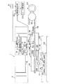
以下、この発明を図示の実施の形態により詳細に説明する。図1は、本実施の形態の自動ドアの解錠装置の概略図である。本自動ドアの解錠装置は電磁錠1及びドア駆動装置15で構成される。上記電磁錠1は、ソレノイド3,回転アーム4,ロックレバー5及びリミットスイッチ6を基板2上に取り付けて構成され、ドア以外の固定体に取り付けられる。回転アーム4は互いにL字を成す第1アーム7と第2アーム8とを有して、軸9を中心に回転可能になっている。そして、第1アーム7の先端部は、ソレノイド3のプランジャ10の先端に回動自在に取り付けられている。一方、第2アーム8の先端部は、ブラケット11に進退可能に取り付けられたロックレバー5の中央部に回動自在に取り付けられている。こうして、ソレノイド3のプランジャ10が出没するに連れて、ロックレバー5はプランジャ10と直交する方向に進退するのである。さらに、ブラケット11にはリミットスイッチ6が取り付けられており、ロックレバー5の一端部5aが基板2に対して所定距離だけ引っ込んだ場合にオンし、出た場合にオフするようになっている。すなわち、本実施の形態においては、上記ロックレバー後退検知手段をリミットスイッチ6で構成するのである。
【0012】
また、上記ドア駆動装置15は、スライドブラケット16,ハンガーブラケット17,タイミングベルト18,タイミングプーリ19およびモータ20で概略構成される。スライドブラケット16は板状に形成されており、一側には、ロックレバー5の一端部5aが挿入される穴21aを有する受け金具21が取り付けられている。また、スライドブラケット16の中央部には、ベルト押さえ22が取り付けられている。このベルト押さえ22は、上側からタイミングベルト18の歯に歯合する歯合板22aと、下側からタイミングベルト18の外面を支持する支持板22bとで構成され、歯合板22aと支持板22bとでタイミングベルト18を挟み込むことによってタイミングベルト18をスライドブラケット16に固定する。
【0013】
上記ハンガーブラケット17はボルト24,25によってスライドブラケット16に取り付けられており、このハンガーブラケット17にはボルト26,27によってドア23が吊り下げられている。また、スライドブラケット16の下側にはローラ28が回転自在に取り付けられており、水平方向に配置されたレール29上を転動可能になっている。
【0014】
以上の構成によって、上記モータ20によってタイミングプーリ19が回転されてタイミングベルト18が回動すると、ローラ28がレール29に案内されてスライドブラケット16およびハンガーブラケット17が図中左右方向にスライドし、ハンガーブラケット17に吊り下げられたドア23が左右に移動することができるのである。但し、ソレノイド3のプランジャ10が突出している場合には、ロックレバー5の一端部5aは基板2に対して所定距離だけ突出して、一端部5aが受け金具21の穴21aに挿入されている。したがって、施錠状態となってドア23はスライドできない。
【0015】
一方、上記ソレノイド3のプランジャ10が没入している場合には、ロックレバー5の一端部5aはスライドブラケット16の受け金具21の穴21aから抜け出し、解錠状態となってドア23はスライド可能になる。その場合には、ロックレバー5の動作によってリミットスイッチ6はオンとなり、リミットスイッチ6からのオン信号がマイクロコンピュータ等で構成される解錠制御部30に送出されるのである。そうすると、解錠制御部30は、リミットスイッチ6からのオン信号とセンサスイッチ31からのオン信号と位置センサ32からの信号に基づいて、後に詳述するような解錠制御処理を行い、ドア23を解放可能と判定するとモータ駆動部33に対して制御信号を出力してドア23を開放させるのである。以下、解錠制御部30によって実行される解錠制御処理動作について詳細に説明する。
【0016】
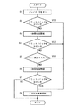
図2は、上記解錠制御処理動作のフローチャートである。自動ドアの入口近傍天井等に設置されているセンサスイッチ31が人を検知してオンし、センサスイッチ31から解錠制御部30にオン信号が送出されると解錠制御処理動作がスタートする。
【0017】
ステップS1で、上記ソレノイド3がオンされてロックレバー5の一端部5aが基板2に対して引っ込められる。ステップS2で、リミットスイッチ6がオンしたか否かが判別される。その結果、オンしていればステップS8に進んでドア通常開放動作に移行し、オフのままであればステップS3に進む。
【0018】
ステップS3で、上記モータ20をドア開放方向(以下、一方向と言う)へ低速(本実施の形態においては50mm/sec)で1秒間だけ回転させるための指令信号をモータ駆動部33に出力する。こうして、1秒間だけドア23を低速で開放させることによって、ドア23と共に移動する受け金具21がロックレバー5に当たってロックレバー5に軽い衝撃が与えられる。したがって、ロックレバー5がごみ詰まり等によって途中で引っ掛かっている場合には、上記衝撃によって引っ掛かりが解除される。ステップS4で、リミットスイッチ6がオンしたか否かが判別される。その結果、オンしていればステップS8に進んでドア通常開放動作に移行し、そうでなければステップS5に進む。
【0019】
ステップS5で、上記位置センサ32からの信号に基づいて、上記ステップS3でのモータ駆動によってドア23が50mm移動したか否かが判別される。その結果、50mm移動していれば、ロックレバー5はドア23の開放に支障無い程度に上がっているか又はロックレバー5は上がっているがリミットスイッチ6が動作していないかであると判定して上記ステップS8に進む。一方、50mm移動していなければステップS6に進む。すなわち、本実施の形態においては、上記ドア移動検知手段を位置センサ32で構成するのである。
【0020】
ステップS6で、上記モータ駆動部33に、上記モータ20を他方向へ低速で1秒間だけ回転させるための指令信号を出力する。こうして、1秒間だけドア23を低速で閉鎖させることによって受け金具21がロックレバー5に上記ステップS3における場合とは反対側から当たり、ロックレバー5に反対側から軽い衝撃が与えられる。ステップS7で、リミットスイッチ6がオンしたか否かが判別される。その結果、オンしていればステップS8に進んでドア通常開放動作に進み、そうでなければソレノイド3,回転アーム4およびロックレバー5の何れかが故障していると判断して解錠制御処理動作を終了する。
【0021】
ステップS8で、上記リミットスイッチ6はオンであるから又はドア23は50mm開放可能であるから、電磁錠1は正常に解錠されたと判断されて、モータ20を上記一方向へ通常速度で回転させるための指令信号がモータ駆動部33に出力される。こうして、ドア通常開放動作を行った後、解錠制御処理動作を終了する。
【0022】
上述のように、本実施の形態においては、解錠制御部30を設けて、センサスイッチ31およびソレノイド3がオンされてもリミットスイッチ6がオンしない場合には、モータ駆動部33を制御してドア23を低速(50mm/sec)で1秒間だけ開放させて受け金具21でロックレバー5に軽い衝撃を与える。そして、リミットスイッチ6がオンするか、あるいは、ドア23が50mm開放している場合にはドア通常開放動作を行う。また、上記何れにも該当しない場合には、更にモータ駆動部33を制御してドア23を50mm/secで1秒間だけ閉鎖させて受け金具21でロックレバー5に反対側から軽い衝撃を与える。そして、リミットスイッチ6がオンした場合にはドア通常開放動作を行うようにしている。
【0023】
このように、本実施の形態においては、上記ロックレバー5に両側から軽い衝撃を与えるので、ロックレバー5がごみ詰まり等で途中で引っ掛かっている場合には、その引っ掛かりを解除してドア23を自動開放できる。また、ドア23が低速で50mm開放した場合にはそのままドア通常開放動作を行うので、ロックレバー5が受け金具21が通過可能程度に後退しているのにリミットスイッチ6が動作していない場合やリミットスイッチ6のみが故障している場合でも、ドア23を自動開放できる。したがって、本実施の形態によれば、従来のような電磁錠1の引っ掛かりやリミットスイッチ6の故障によるトラブルは殆ど解消できる。尚、ドア23が低速で50mm開放したことを検知してそのままドア通常開放動作を行う場合、ドア23のスタート時に若干開放速度が遅くはなるが殆ど通行に支承は無い。
【0024】
尚、上記実施の形態においては、上記ステップS3あるいはステップS6において低速開閉する距離は50mmとしているが、この発明においてはこれに限定するものではない。要は、受け金具21の穴21aがロックレバー5に引っ掛からずに通過可能な最短距離であればよいのである。但し、その場合のドア23開閉の速度は、上記最短距離を1秒程度で移動可能な速度である必要がある。また、上記実施の形態においては、ロックレバー5の一端部5aが受け金具21の穴21aに挿入することによってロックレバー5は受け金具21に係合されるが、ロックレバー5と受け金具21との係合手段はこれに限定されるものではない。
【0025】
【発明の効果】
以上より明らかなように、請求項1に係る発明の自動ドアの解錠装置は、ドアに取り付けられた金具に係合されるロックレバーの後退を指示したにもかかわらず、上記ロックレバーが後退したことを検知するロックレバー後退検知手段からの検知信号がない場合であっても、開閉手段によってドアを所定距離だけ開く方向に移動させて上記金具をロックレバーに当接させるので、上記金具でロックレバーに軽い衝撃を与えることができる。したがって、上記ロックレバーがごみ詰まり等で引っ掛かっている場合には、その引っ掛かりを上記衝撃によって解除してドアを開放可能にできる。
【0026】
また、請求項2に係る発明の自動ドアの解錠装置における上記制御手段は、上記ドアが上記所定距離だけ移動したことを検知するドア移動検知手段からの検知信号があった場合には、上記開閉手段によって上記ドアを開放させるので、上記ロックレバーが上記金具に係合されない程度に引っ込んでいるのに上記ロックレバー後退検知手段からの検知信号がない場合や上記ロックレバー後退検知手段が故障している場合であっても、上記ドアを開放できる。
【0027】
また、請求項3に係る発明の自動ドアの解錠装置における上記制御手段は、ドア移動検知手段からの検知信号がなかった場合には、上記開閉手段によって上記ドアを閉じて再度上記所定距離だけ開く方向に移動させて上記金具を上記ロックレバーに再度当接させるので、上記金具でロックレバーに一度軽い衝撃を与えても上記ロックレバーの引っ掛かりが解除されない場合には、上記金具でロックレバーに再度軽い衝撃を与えることができる。したがって、上記ロックレバーの引っ掛かりを、上記二度の衝撃によって容易に解除することができる。
【図面の簡単な説明】
【図1】この発明の自動ドアの解錠装置の概略図である。
【図2】図1における解錠制御部によって実行される解錠制御処理動作のフローチャートである。
【符号の説明】
1…電磁錠、 3…ソレノイド、
4…回転アーム、 5…ロックレバー、
6…リミットスイッチ、 15…ドア駆動装置、
16…スライドブラケット、 17…ハンガーブラケット、
18…タイミングベルト、 19…タイミングプーリ、
20…モータ、 21…受け金具、
22…ベルト押さえ、 23…ドア、
28…ローラ、 29…レール、
30…解錠制御部、 31…センサスイッチ、
32…位置センサ、 33…モータ駆動部。[0001]
BACKGROUND OF THE INVENTION
The present invention relates to an improvement in an automatic door unlocking device.
[0002]
[Prior art]
Automatic doors such as apartments and cash corners are equipped with electromagnetic locks, which are unlocked when the door activation sensor is turned on. When the unlocking of the electromagnetic lock is confirmed by, for example, a limit switch, an ON signal is sent to the automatic door opening / closing mechanism to open the automatic door.
[0003]
[Problems to be solved by the invention]
However, in the conventional automatic door unlocking device, when the lock lever constituting the electromagnetic lock cannot be completely removed from the metal fitting on the door side due to clogging of dust or the like, or the lock lever is completely removed from the metal fitting. There are many cases where the limit switch that detects this does not conduct due to the adhering of dust. In the above case, there is a problem in that the automatic door cannot be opened because an ON signal is not output from the limit switch to the opening / closing mechanism. In particular, in the latter case, although the electromagnetic lock is unlocked, the automatic door is not opened, and a serious problem such as breakage of the door glass occurs.
[0004]
SUMMARY OF THE INVENTION Accordingly, an object of the present invention is to provide an automatic door unlocking device that can avoid unlocking failure due to dust clogging or the like.
[0005]
[Means for Solving the Problems]
In order to achieve the above object, the invention according to claim 1 has advanced by being attached to a bracket having an engaging portion attached to a door that is opened and closed by opening and closing means and a fixed body other than the door so as to be able to advance and retract. An automatic door unlocking device for unlocking an automatic door having a lock lever that locks the door by engaging the engagement portion of the metal fitting with the tip, and detecting the backward movement of the lock lever a lock lever retraction detecting means, in a case where an instruction to retraction of the lock lever, and, when there is no detection signal representing the retraction from the lock lever retraction detecting means, the predetermined distance the door by the opening and closing means It is characterized in that it is provided with control means for moving it only in the opening direction so that the metal fitting comes into contact with the lock lever.
[0006]
According to the above configuration, when there is no output of a detection signal from the lock lever retraction detection means even though the retraction of the lock lever is instructed, a light impact is given to the lock lever by the metal fitting attached to the door. Therefore, when the lock lever is caught on the way due to dirt clogging or the like, the catch is released by the impact and the door can be opened.
[0007]
According to a second aspect of the present invention, in the automatic door unlocking device according to the first aspect of the present invention, the automatic door unlocking device further includes door movement detection means for detecting that the door has moved by the predetermined distance, and the control means includes: When the detection signal indicating the movement of the predetermined distance from the door movement detection means is present when the door is moved in the opening direction by a predetermined distance, the door is opened. It is a feature.
[0008]
According to the above configuration, the door is opened as it is when the predetermined distance is opened. Therefore, even when the lock lever is retracted to the extent that it is not engaged with the metal fitting, there is no detection signal from the lock lever retraction detection means, or even when the lock lever retraction detection means is out of order, The door is opened.
[0009]
According to a third aspect of the present invention, in the automatic door unlocking device according to the second aspect of the invention, the control means moves the door in a direction to open the door by a predetermined distance. If there is no detection signal indicating the movement of the predetermined distance from the door, the opening / closing means moves the door in the closing direction, and then moves the door in the opening direction again to move the bracket to the lock lever. It is characterized in that it can come into contact again.
[0010]
According to the above configuration, if the lock lever is not released even if a light impact is once applied to the lock lever by the metal fitting attached to the door, the light impact is again applied to the lock lever by the metal fitting. Therefore, the lock lever is easily released by the two impacts.
[0011]
DETAILED DESCRIPTION OF THE INVENTION
Hereinafter, the present invention will be described in detail with reference to the illustrated embodiments. FIG. 1 is a schematic view of an automatic door unlocking device of the present embodiment. The automatic door unlocking device includes an electromagnetic lock 1 and a
[0012]
The
[0013]
The
[0014]
With the above configuration, when the
[0015]
On the other hand, when the
[0016]
FIG. 2 is a flowchart of the unlock control processing operation. When the
[0017]
In step S1, the solenoid 3 is turned on, and the one end 5a of the
[0018]
In step S3, a command signal for rotating the motor 20 in the door opening direction (hereinafter referred to as one direction) at a low speed (50 mm / sec in the present embodiment) for only one second is output to the motor drive unit 33. . In this way, by opening the
[0019]
In step S5, based on the signal from the
[0020]
In step S6, a command signal for rotating the motor 20 in the other direction at a low speed for only 1 second is output to the motor drive unit 33. In this way, by closing the
[0021]
In step S8, since the limit switch 6 is ON or the
[0022]
As described above, in the present embodiment, the
[0023]
As described above, in this embodiment, a light impact is applied to the
[0024]
In the above-described embodiment, the low-speed opening / closing distance in step S3 or step S6 is 50 mm. However, the present invention is not limited to this. The point is that the hole 21a of the
[0025]
【The invention's effect】
As is clear from the above, the unlocking device for the automatic door according to the first aspect of the invention is directed to retract the lock lever, even though the lock lever engaged with the metal fitting attached to the door is instructed. Even if there is no detection signal from the lock lever retraction detection means that detects that the door has been moved, the opening and closing means moves the door in a direction that opens a predetermined distance so that the metal fitting comes into contact with the lock lever. A light impact can be given to the lock lever. Therefore, when the lock lever is caught by clogging or the like, the catch can be released by the impact and the door can be opened.
[0026]
Further, the control means in the automatic door unlocking device of the invention according to claim 2 is characterized in that when there is a detection signal from the door movement detection means for detecting that the door has moved by the predetermined distance, Since the door is opened by the opening / closing means, there is no detection signal from the lock lever retraction detection means even though the lock lever is retracted to such an extent that the lock lever is not engaged with the metal fitting, or the lock lever retraction detection means fails. Even if it is, it can open the door.
[0027]
Further, the control means in the automatic door unlocking device of the invention according to claim 3 is configured to close the door by the opening / closing means, and again to the predetermined distance when there is no detection signal from the door movement detecting means. Since the bracket is re-contacted with the lock lever by moving it in the opening direction, if the lock lever is not released even if a slight impact is applied to the lock lever once with the bracket, the bracket can be moved to the lock lever with the bracket. A light shock can be given again. Therefore, the lock lever can be easily released by the two impacts.
[Brief description of the drawings]
FIG. 1 is a schematic view of an automatic door unlocking device of the present invention.
FIG. 2 is a flowchart of an unlocking control processing operation executed by an unlocking control unit in FIG.
[Explanation of symbols]
1 ... Electromagnetic lock, 3 ... Solenoid,
4 ... Rotating arm, 5 ... Lock lever,
6 ... limit switch, 15 ... door drive,
16 ... Slide bracket, 17 ... Hanger bracket,
18 ... Timing belt, 19 ... Timing pulley,
20 ... motor, 21 ... receiving bracket,
22 ...
28 ... Roller, 29 ... Rail,
30 ... Unlocking control unit, 31 ... Sensor switch,
32: Position sensor, 33: Motor drive unit.
Claims (3)
上記ロックレバーの後退を検知するロックレバー後退検知手段と、
上記ロックレバーの後退を指示した場合であって、且つ、上記ロックレバー後退検知手段からの後退を表す検知信号がない場合には、上記開閉手段によって上記ドアを所定距離だけ開く方向に移動させて上記金具を上記ロックレバーに当接させる制御手段
を備えたことを特徴とする自動ドアの解錠装置。A fitting having an engagement portion attached to a door that is opened and closed by an opening / closing means and a fixed body other than the door so as to be able to advance and retreat, and when advanced, the tip engages with the engagement portion of the fitting. An automatic door unlocking device for unlocking an automatic door having a lock lever for locking the door,
Lock lever retraction detection means for detecting retraction of the lock lever;
In a case where an instruction to retraction of the lock lever, and, when there is no detection signal representing the retraction from the lock lever retraction detecting means, is moved in the direction of opening the door a predetermined distance by said switching means An automatic door unlocking device comprising control means for bringing the metal fitting into contact with the lock lever.
上記ドアが上記所定距離だけ移動したことを検知するドア移動検知手段を備えると共に、
上記制御手段は、上記ドアを所定距離だけ開く方向に移動させた際に上記ドア移動検知手段からの上記所定距離の移動を表す検知信号があった場合には、上記ドアを開放するようになっている
ことを特徴とする自動ドアの解錠装置。The automatic door unlocking device according to claim 1,
A door movement detecting means for detecting that the door has moved by the predetermined distance;
The control means opens the door when there is a detection signal indicating movement of the predetermined distance from the door movement detection means when the door is moved in a direction to open the predetermined distance. An automatic door unlocking device characterized by that.
上記制御手段は、上記ドアを所定距離だけ開く方向に移動させた際に上記ドア移動検知手段からの上記所定距離の移動を表す検知信号がなかった場合には、上記開閉手段によって上記ドアを閉じる方向に移動させた後、再度開く方向に上記所定距離移動させて上記金具を上記ロックレバーに再度当接し得るようになっている
ことを特徴とする自動ドアの解錠装置。The automatic door unlocking device according to claim 2 ,
The control means closes the door by the opening / closing means when there is no detection signal indicating the movement of the predetermined distance from the door movement detection means when the door is moved in the opening direction by a predetermined distance. An automatic door unlocking device, wherein the metal door can be brought into contact with the lock lever again after being moved in the direction and then moved in the opening direction again by the predetermined distance.
Priority Applications (1)
| Application Number | Priority Date | Filing Date | Title |
|---|---|---|---|
| JP19860198A JP3607082B2 (en) | 1998-07-14 | 1998-07-14 | Automatic door unlocking device |
Applications Claiming Priority (1)
| Application Number | Priority Date | Filing Date | Title |
|---|---|---|---|
| JP19860198A JP3607082B2 (en) | 1998-07-14 | 1998-07-14 | Automatic door unlocking device |
Publications (2)
| Publication Number | Publication Date |
|---|---|
| JP2000027533A JP2000027533A (en) | 2000-01-25 |
| JP3607082B2 true JP3607082B2 (en) | 2005-01-05 |
Family
ID=16393916
Family Applications (1)
| Application Number | Title | Priority Date | Filing Date |
|---|---|---|---|
| JP19860198A Expired - Fee Related JP3607082B2 (en) | 1998-07-14 | 1998-07-14 | Automatic door unlocking device |
Country Status (1)
| Country | Link |
|---|---|
| JP (1) | JP3607082B2 (en) |
Families Citing this family (2)
| Publication number | Priority date | Publication date | Assignee | Title |
|---|---|---|---|---|
| CN102183422B (en) * | 2011-03-15 | 2013-01-09 | 浙江大学 | Locking mechanism and impact tester device having locking mechanism |
| JP6214599B2 (en) * | 2015-06-15 | 2017-10-18 | 株式会社ソリック | Auto-lock device |
-
1998
- 1998-07-14 JP JP19860198A patent/JP3607082B2/en not_active Expired - Fee Related
Also Published As
| Publication number | Publication date |
|---|---|
| JP2000027533A (en) | 2000-01-25 |
Similar Documents
| Publication | Publication Date | Title |
|---|---|---|
| US6698804B2 (en) | Electric door lock device of motor vehicle | |
| JP3773731B2 (en) | Door lock device | |
| JPH082351Y2 (en) | Automatic lid locking system for automobiles | |
| JP4300858B2 (en) | Vehicle door control device | |
| EP1076141B1 (en) | Door lock device for motor vehicles | |
| JP4130020B2 (en) | Elevator control panel opening and closing device | |
| US20060175868A1 (en) | Door apparatus | |
| JPH07116878B2 (en) | Semi-automatic door opener for automobiles | |
| CA2103310A1 (en) | Latching apparatus for double doors | |
| EP4170115B1 (en) | Door handle control device of vehicle | |
| KR101084755B1 (en) | Front door with auxiliary door | |
| EP0026763A1 (en) | Locking device for vertical sliding gates and similar | |
| JP3607082B2 (en) | Automatic door unlocking device | |
| JP4520709B2 (en) | Safety switch | |
| US9085921B2 (en) | Unlocking device | |
| JP3517193B2 (en) | Sliding door locking device | |
| JP4960809B2 (en) | Door opener | |
| CN215830225U (en) | Latch bolt guide structure and door lock | |
| KR20080038667A (en) | Automatic window lock | |
| JP4142177B2 (en) | Elevator door safety device | |
| JPS6128853Y2 (en) | ||
| JP4166070B2 (en) | Electric door latch device | |
| JPH0634555Y2 (en) | Fixing device for the middle pillar of electric shutter for building | |
| JP2593776Y2 (en) | Control circuit of closure device | |
| KR100728455B1 (en) | Control device for opening of the sliding door of the vehicle |
Legal Events
| Date | Code | Title | Description |
|---|---|---|---|
| TRDD | Decision of grant or rejection written | ||
| A01 | Written decision to grant a patent or to grant a registration (utility model) |
Free format text: JAPANESE INTERMEDIATE CODE: A01 Effective date: 20040928 |
|
| A61 | First payment of annual fees (during grant procedure) |
Free format text: JAPANESE INTERMEDIATE CODE: A61 Effective date: 20041006 |
|
| R150 | Certificate of patent (=grant) or registration of utility model |
Free format text: JAPANESE INTERMEDIATE CODE: R150 |
|
| FPAY | Renewal fee payment (prs date is renewal date of database) |
Free format text: PAYMENT UNTIL: 20071015 Year of fee payment: 3 |
|
| FPAY | Renewal fee payment (prs date is renewal date of database) |
Free format text: PAYMENT UNTIL: 20101015 Year of fee payment: 6 |
|
| FPAY | Renewal fee payment (prs date is renewal date of database) |
Free format text: PAYMENT UNTIL: 20101015 Year of fee payment: 6 |
|
| S531 | Written request for registration of change of domicile |
Free format text: JAPANESE INTERMEDIATE CODE: R313531 |
|
| FPAY | Renewal fee payment (prs date is renewal date of database) |
Free format text: PAYMENT UNTIL: 20101015 Year of fee payment: 6 |
|
| R350 | Written notification of registration of transfer |
Free format text: JAPANESE INTERMEDIATE CODE: R350 |
|
| FPAY | Renewal fee payment (prs date is renewal date of database) |
Free format text: PAYMENT UNTIL: 20101015 Year of fee payment: 6 |
|
| S111 | Request for change of ownership or part of ownership |
Free format text: JAPANESE INTERMEDIATE CODE: R313113 |
|
| FPAY | Renewal fee payment (prs date is renewal date of database) |
Free format text: PAYMENT UNTIL: 20101015 Year of fee payment: 6 |
|
| R350 | Written notification of registration of transfer |
Free format text: JAPANESE INTERMEDIATE CODE: R350 |
|
| FPAY | Renewal fee payment (prs date is renewal date of database) |
Free format text: PAYMENT UNTIL: 20111015 Year of fee payment: 7 |
|
| FPAY | Renewal fee payment (prs date is renewal date of database) |
Free format text: PAYMENT UNTIL: 20111015 Year of fee payment: 7 |
|
| FPAY | Renewal fee payment (prs date is renewal date of database) |
Free format text: PAYMENT UNTIL: 20121015 Year of fee payment: 8 |
|
| FPAY | Renewal fee payment (prs date is renewal date of database) |
Free format text: PAYMENT UNTIL: 20121015 Year of fee payment: 8 |
|
| FPAY | Renewal fee payment (prs date is renewal date of database) |
Free format text: PAYMENT UNTIL: 20131015 Year of fee payment: 9 |
|
| R250 | Receipt of annual fees |
Free format text: JAPANESE INTERMEDIATE CODE: R250 |
|
| R250 | Receipt of annual fees |
Free format text: JAPANESE INTERMEDIATE CODE: R250 |
|
| LAPS | Cancellation because of no payment of annual fees |