JP3607077B2 - Printing device output tray - Google Patents
Printing device output tray Download PDFInfo
- Publication number
- JP3607077B2 JP3607077B2 JP14987998A JP14987998A JP3607077B2 JP 3607077 B2 JP3607077 B2 JP 3607077B2 JP 14987998 A JP14987998 A JP 14987998A JP 14987998 A JP14987998 A JP 14987998A JP 3607077 B2 JP3607077 B2 JP 3607077B2
- Authority
- JP
- Japan
- Prior art keywords
- collision
- printing paper
- paper
- printing
- collision material
- Prior art date
- Legal status (The legal status is an assumption and is not a legal conclusion. Google has not performed a legal analysis and makes no representation as to the accuracy of the status listed.)
- Expired - Fee Related
Links
Images
Landscapes
- Pile Receivers (AREA)
Description
【0001】
【発明の属する技術分野】
本発明は、印刷装置から送り出される印刷済の印刷用紙の進行を、突き当て部材を以てせき止め、基板上に落下させて積層させる排紙台にかかり、特に、印刷用紙が突き当て部材に衝突する際に生じる衝突騒音を無くすとともに、突き当て部材からの跳ね返りを抑止して適宜に紙揃えをする印刷装置の排紙台に関するものである。
【0002】
【従来の技術】
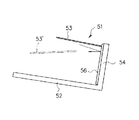
図9は、従来における印刷装置の排紙台を示す側面図である。排紙台51は、少なくとも、印刷用紙53を積載する基板52と、この基板52より立設された突き当て板54とから構成されている。そして、印刷装置から飛ばして送り出される印刷済の印刷用紙53の進行を、突き当て板54でせき止め、基板52上に落下させるようにしている。
【0003】
従来、このような排紙台51において、突き当て板54には、送り出された印刷用紙53が当接する部位に、硬質プラスチックあるいはゴム板などの衝突部材56が配されている。そして、この衝突部材56によって、衝突した印刷用紙53の跳ね返りを抑え、基板52上できれいに揃うようにしている。
【0004】
【発明が解決しようとする課題】
しかしながら、上述した従来の印刷用紙の排紙台1では、突き当て板54に配された衝突部材56が硬質プラスチックあるいはゴム板などで構成されており、且つ、飛ばされて排紙される印刷用紙53に勢いがあるため、印刷用紙53が突き当て板54(衝突部材56)に衝突した際には、大きな衝突音が発生することとなる。なお、近年の印刷装置は、使い勝手が向上し、専用の印刷室からオフィス内に設置される傾向にあるために、上記衝突音は、作業環境を悪化させるものとして問題となっている。
【0005】
このため、衝突部材56として、スポンジなどの発泡性弾性材のように柔らかい材質を採用し、衝突音を無くす試みがあった。ところが、柔らかい材質の衝突部材56では、衝突音は低減されるが、図9に一点鎖線で示すように、衝突した印刷用紙53’が大きく跳ね返ってしまい、基板52上での紙揃えが悪くなるという問題が生じる。
【0006】
そこで本発明は、上記課題を解消するために、印刷用紙の排紙時の衝突音を無くし、且つ、良好に紙揃えを行うことができる印刷装置の排紙台を提供することを目的としている。
【0007】
【課題を解決するための手段】
上記目的を達成するため本発明による印刷装置の排紙台は、印刷済の印刷用紙を積載する基体と、該基体に立設されて送り出された前記印刷用紙が衝突する突き当て体とを有する印刷装置の排紙台において、
前記突き当て体の前記印刷用紙が衝突する部位には、ゲル状物質からなる衝突面に微粒子コーティングが施された衝突材が設けられていることを特徴とする。
【0008】
前記衝突材におけるゲル状物質は、アスカーC硬度が略3〜30°の範囲内とされていることを特徴とする。
【0009】
前記衝突材における微粒子コーティングは、粒径略3〜100μmとされた炭酸カルシウム粉末またはアルミ粉末からなることを特徴とする。
【0010】
前記衝突材は、上下方向に連続して突出する突条をなし、左右幅方向に複数併設され、該突条間には上下方向に連続する溝条が形成され、この衝突材の下側であって送り出された前記印刷用紙が衝突しない部位には、前記衝突材の前記衝突面と面一となる滑面部が設けられたことを特徴とする。
【0011】
前記衝突材、または前記滑走部を伴う前記衝突材は、前記突き当て体に対して着脱自在なユニットとして構成されたことを特徴とする。
【0012】
本発明によれば、送り出された印刷用紙は、ゲル状物質からなる衝突材に衝突するため、衝突音や跳ね返りが生じることなく受け止められる。また、衝突材に衝突した印刷用紙は、衝突材の衝突面に施された微粒子コーティングにより、衝突面に接触したままの状態で滑るように落下し、基体上で適宜揃えられる。
【0013】
【発明の実施の形態】
以下、本発明の実施の形態を図面を参照して具体的に説明する。
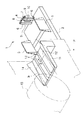
図1は本発明による印刷装置の排紙台を示す斜視図、図2は同排紙台の要部を示す斜視図である。
【0014】
この実施の形態における印刷装置の排紙台1は、印刷済の印刷用紙Wを積載する載置台としての板状の基体2と、この基体2から上方に立設された突き当て体4とを有している。突き当て体4は、板状に形成され、印刷装置本体Pから送り出された印刷用紙Wの先端を衝突させ、その進行を阻止するように、基体2の後方、つまり、印刷用紙Wの排紙方向の略端部に配されている。また、基体2上には、排出口から送り出される印刷用紙Wの両側縁部を規制して、印刷用紙Wの幅方向の位置を揃える公知の側板5が設けられている。
【0015】
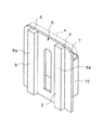
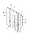
突き当て体4において、印刷用紙Wの先端が衝突するべき前方の面には、衝突材6が配設されている。この衝突材6は、図2に示すように、突き当て体4の前面に沿って設けられた取付板7に配されている。衝突材6は、取付板7の前面において、上下方向に連続して突出する突条をなし、左右幅方向に複数(この実施の形態では二箇所)併設され、各々の間で上下方向に連通する溝条8をなしている。また、衝突材6の前面は、印刷装置本体Pから送り出された印刷用紙Wの先端が突出する略平坦な衝突面6aをなしている。
【0016】
また、上記のように形成された衝突材6は、ゲル状物質により成形されている。このゲル状物質は、本実施の形態では、特殊ポリマーの三次元網目構造がオイル成分を保持する非水系高分子ゲルを採用している。非水系高分子ゲルとしては、例えば熱可塑性エラストマーにアスファルト系オイルを複合させた材料(商品名:MNCS:ムンスク(株)ブリジストン製)、可塑性エラストマーとしてポリエチレンを主成分とし、鉱物油を複合させた材料(商品名:コスモゲル(株)コスモ計器製)などがある。
【0017】
さらに、本実施の形態にて採用するゲル状物質は、JIS K6301(1975年制定)に規定されたスプリング式硬さ試験機C形(アスカーC)による測定硬度が略3〜30°の範囲内とされている。
【0018】
ここで、JIS K 6301(1975年制定)に規定された硬さ試験について説明する。前記規格は加硫ゴム物理試験方法に関する。同規格は、加硫ゴム物理試験方法の一つとして硬さ試験を規定している。
【0019】
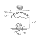
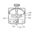
この硬さ試験に使用される器具の一つであるスプリング硬さ試験機のC形を、図3〜図5に示す。図3および図4に示すように、この試験機は筐体100を有している。筐体100の下面は、被測定物に押しつけられる加圧面101である。加圧面101の略中心部において、筐体100には針孔102が貫通している。筐体100の内部には押針103が設けられている。押針103の先端部は、前記加圧面101の針孔102を挿通して筐体100の外に突出している。押針103の後端部は、筐体100の内部に設けられたばね104に固定されている。
【0020】
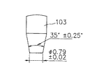
図5に示すように、押針103は断面円形の棒体であり、先端部は角度35±0.25°のテーパ面を有する円錐台状であり、その先端の直径は0.79±0.02mmである。筐体100の内部には押針103の軸方向の移動に連動して揺動する指針105が設けられている。筐体100には前記指針105が指示する硬度の目盛りが記載された目盛盤106が設けられている。
【0021】
測定時には、前記C形のスプリング硬さ試験機を垂直に保ち、押針103が被測定物の被測定面に垂直になるように加圧面101を5000gf{49.03N}の荷重で圧着させる。加圧面101の針孔102から筐体100の外に突出した押針103は、被測定面に突き当たって筐体100内に押し戻される。押針103の移動量に対応して指針105が揺動し、硬度を示す目盛盤106上の数値を指し示す。
【0022】
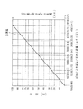
前記ばね104により前記押針103の先端に加わる荷重(gf(N))と、前記目盛盤106にて指示される硬度の目盛(度)と、前記加圧面101と前記押針103との距離(mm)との関係を示すグラフを図6に示す。
【0023】
図2に示すように、衝突材6の衝突面6aには、微粒子コーティング9が施されている。この、微粒子コーティング9は、粒径略3〜100μmとされた炭酸カルシウム粉末またはアルミ粉末からなり、適宜接着剤などにより衝突面6aに施される。なお、微粒子コーティング9の粒径は、印刷装置から送り出される印刷用紙Wの厚さ(凡そ80μm前後)よりも小さい径であることが好ましい。
【0024】
また、上述のような衝突材6が設けられた取付板7は、突き当て体4に対して着脱自在に取り付けられるようにユニット化されている。この着脱自在な構成は、本実施の形態では、取付板7の後面側に、伸縮自在あるいは伸縮しない保持ベルト10が取付板7の後面の一部とともに環状となるように設けられている。そして、この保持ベルト10を以て突き当て体4を通すようにして、突き当て体4に取付板7(衝突材6)を装着する。なお、突き当て体4に対する着脱自在な構成は、図示した構成に限らず、面ファスナー、ホック、フック、ネジ止めなどの係着手段を用いてもよい。
【0025】
ところで、印刷装置本体Pから上記排紙台1に送り出される印刷用紙Wは、搬送部11を介して送り出される。
搬送部11は、図1に示すように、搬送路12と、搬送ベルト13と、ウィング14とを備えている。搬送路12は、略水平とされた平坦面をなしている。この搬送路12には、印刷装置本体P内にある印刷部(主に版胴)15から送られた印刷済の印刷用紙Wが載る。搬送ベルト13は、搬送路12の前後方向に沿って配された無端状のベルト部材であって、搬送路12上を図1中矢印A方向に駆動し、搬送路12上の印刷用紙Wを搬送する。ウィング14は、搬送路12の両側部において、互いに向き合う斜面をなし、搬送路12上を搬送される印刷用紙Wの両側部を上方に反らせて、印刷用紙WをU字状に癖付けさせる。
【0026】
このように、搬送部11を介して送り出される印刷用紙Wは、排紙台1に向かって安定した高さで飛ばされることとなる。ゆえに、続いて飛ばされる印刷用紙Wは、前に排紙台1に送られた印刷用紙Wの印刷面(表面)に対して、次に排紙台1に送られた印刷用紙Wの裏面が擦るようなことがなく、突き当て体4に衝突する所まで飛ばされる。
【0027】
以下、上記のように構成された排紙台1への印刷用紙Wの排紙動作を説明する。図7は排紙台における排紙動作を示す側面図である。
ここで、排紙台1をなす基体2は、その後端が低くなるように傾けられており、基体2に配設された突き当て体4(衝突材6の衝突面6a)は上方に傾斜している。
【0028】
図7に示すように、上述の如く、搬送部11においてU字状に癖付けられつつ勢いよく送り出された印刷済の印刷用紙W(W1)は、基体2上を飛翔して先端が突き当て体4に配された衝突材6の衝突面6aに衝突する。
【0029】
衝突材6の衝突面6aに衝突した印刷用紙W(W2)は、その衝突した衝撃が、衝突材6をなすゲル状物質に吸収されて跳ね返ることなく、衝突面6aに接触したまま落下する。この際、衝突材6は、その材質(ゲル状物質)によって、印刷用紙W(W2)の衝突音を打ち消すこととなる。
【0030】
また、衝突面6aに接触する印刷用紙W(W2)の先端は、衝突面6aに施された微粒子コーティング9によって、ゲル状物質との間の摩擦抵抗が低減され、衝突面6a上を滑るようにして落下する。さらに、落下する印刷用紙W(W2)の先端下面には、その落下を妨げる空気が存在するが、各衝突材6の間の溝条8が前記空気を逃がす。
【0031】
また、衝突面6aに接触しつつ落下する印刷用紙W(W3)は、基体2上に積載される。このように、印刷用紙Wが衝突面6aに沿って落下することにより、基体2上において、前に排紙された印刷用紙W(W0)と揃うようにして均一に積層される。
【0032】
したがって、このように構成された印刷装置の排紙台では、飛翔して送り出される印刷用紙Wの進行を妨げる如く突き当てする部位にゲル状物質からなる衝突材6を配したので、衝突した印刷用紙Wの跳ね返り、および衝突音を無くす。
【0033】
また、印刷用紙Wが衝突する衝突材6の衝突面6aに微粒子コーティング9を施したので、跳ね返りがなく衝突面6aに接触する印刷用紙Wとの間の摩擦抵抗を低減し、衝突面6aに接触したままの状態で印刷用紙Wを基体2上に落下させ、基体2上に後続する印刷用紙Wを適宜に揃える。
【0034】
また、上記衝突材6は、突き当て体4に対して着脱自在とされた取付板7を以てユニット化されているので、衝突材6が汚れたり、劣化した際の取り替えが容易に行える。さらに、衝突材6を備えていない排紙台への衝突材6の設置が行える汎用性を有する。
【0035】
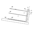
なお、上述した実施の形態において、衝突材6は取付板7(突き当て体4)の上下方向に連続するように設けられているが、この限りではない。具体的には、飛翔して送り出される印刷用紙Wは、搬送部11によってU字状に癖付けられて安定して飛ばされるので、衝突材6に対して突き当たる部位がほとんど可変しない(搬送部11における搬送速度が可変しない場合)。このため、図8に示すように、取付板7に対し、印刷用紙Wが衝突する部位に衝突材6(微粒子コーティング9を備えている)を配し、その下方に、衝突材6の衝突面6aと面一に連続する滑面部16を設ける。この滑面部16は、印刷用紙Wとの摩擦抵抗が少ないABS樹脂などの合成樹脂材からなる。
【0036】
このように衝突材6の下方に滑面部16を設ければ、ゲル状物質である衝突材6を無駄にすることがなく、且つ、上述の作用を実施することが可能である。
【0037】
なお、上述した実施の形態では、衝突材6の前面は、印刷装置本体Pから送り出された印刷用紙Wの先端が突出する略平坦な衝突面6aをなしているが、この限りでなく、例えば、衝突面6aを円弧状に形成したり、上下方向に沿った溝を有した櫛歯状に形成してもよい。
【0038】
また、上述した実施の形態では、衝突材6は、突き当て体4に着脱自在とされた取付板7に配されているが、突き当て体4に直接設けてもよい。
【0039】
【発明の効果】
以上説明したように本発明による印刷装置の排紙台は、印刷装置側から送り出された印刷済の印刷用紙を、ゲル状物質からなる衝突面に微粒子コーティングが施された衝突材を以て受け止めている。これにより、衝突した印刷用紙の跳ね返り、および衝突音を無くすことができる。さらに、衝突面にある微粒子コーティングにより印刷用紙との間の摩擦抵抗を低減するので、跳ね返ることなく衝突面に接触する印刷用紙を円滑に基体上に落下させ、続いて送り出される印刷用紙を適宜揃えることができる。
【0040】
また、前記衝突材におけるゲル状物質を、アスカーC硬度が略3〜30°の範囲内としたことにより、衝突した印刷用紙の跳ね返り、および衝突音を適宜無くすことができる。
【0041】
また、前記衝突材における微粒子コーティングを、粒径略3〜100μmとされた炭酸カルシウム粉末またはアルミ粉末を以て施したことにより、印刷用紙との間の摩擦抵抗を適宜低減することができる。
【0042】
また、衝突材の下側であって送り出された印刷用紙が衝突しない部位に、衝突材の衝突面と面一となる滑面部を設けたことにより、ゲル状物質に微粒子コーティングが施された衝突材を適量として無駄にすることがなく、且つ、上述の効果を適宜なすことができる。さらに、落下する印刷用紙に先端下面には、その落下を妨げる空気が存在するが、衝突材間の溝条が空気を逃がすことになる。
【0043】
また、衝突材、または滑走部を伴う衝突材を、突き当て体に対して着脱自在なユニットとして構成したことにより、衝突材の取り替えが容易であり、さらには衝突材を備えていない排紙台への衝突材の設置が行える汎用性を備えることができる。
【図面の簡単な説明】
【図1】本発明による印刷装置の排紙台を示す斜視図。
【図2】同排紙台の要部を示す斜視図。
【図3】JIS K 6301(1975年制定)に規定されたスプリング式硬さ試験機C形の正面図。
【図4】JIS K 6301(1975年制定)に規定されたスプリング式硬さ試験機C形の内部機構を示す図。
【図5】JIS K 6301(1975年制定)に規定されたスプリング式硬さ試験機C形の押針の先端部の部分拡大図。
【図6】JIS K 6301(1975年制定)に規定されたスプリング式硬さ試験機C形において、ばねにより押針の先端に加わる荷重〔gf{N}〕と、目盛盤にて指示される硬度の目盛(度)と、加圧面と押針との距離(mm)との関係を示す図。
【図7】本発明の排紙台における排紙動作を示す側面図。
【図8】本発明の排紙台における要部の他の構成を示す斜視図。
【図9】従来における印刷装置の排紙台を示す側面図。
【符号の説明】
1…排紙台、2…基体、4…突き当て体、6…衝突材、6a…衝突面、9…微粒子コーティング、16…滑面部、W…印刷用紙。[0001]
BACKGROUND OF THE INVENTION
The present invention is applied to a paper discharge tray that blocks the progress of printed printing paper delivered from a printing apparatus with an abutting member and drops the substrate onto a substrate, and in particular, when the printing paper collides with the abutting member. In addition, the present invention relates to a paper discharge tray of a printing apparatus that eliminates the collision noise generated in the printer and suppresses the rebound from the abutting member and appropriately aligns the paper.
[0002]
[Prior art]
FIG. 9 is a side view showing a discharge tray of a conventional printing apparatus. The
[0003]
Conventionally, in such a
[0004]
[Problems to be solved by the invention]
However, in the above-described conventional printing paper discharge tray 1, the
[0005]
For this reason, there has been an attempt to eliminate a collision sound by using a soft material such as a foaming elastic material such as sponge as the
[0006]
SUMMARY OF THE INVENTION In order to solve the above-described problems, an object of the present invention is to provide a discharge tray of a printing apparatus that can eliminate a collision sound when discharging a print sheet and can satisfactorily align the sheets. .
[0007]
[Means for Solving the Problems]
In order to achieve the above object, a discharge tray of a printing apparatus according to the present invention includes a base on which printed printing paper is stacked, and an abutting body on which the printing paper that is erected on the base collides with the base. In the output tray of the printing device,
In the abutting body, a portion where the printing paper collides is provided with a collision material having a fine particle coating on a collision surface made of a gel substance.
[0008]
The gel-like substance in the collision material has an Asker C hardness of approximately 3 to 30 °.
[0009]
The fine particle coating on the impact material is made of calcium carbonate powder or aluminum powder having a particle size of about 3 to 100 μm.
[0010]
The collision material has a protrusion that protrudes continuously in the vertical direction, and a plurality of protrusions are provided in the left-right width direction, and a groove continuous in the vertical direction is formed between the protrusions. In addition, a smooth surface portion that is flush with the collision surface of the collision material is provided at a portion where the sent printing paper does not collide.
[0011]
The collision material or the collision material with the sliding portion is configured as a unit that is detachable from the abutting body.
[0012]
According to the present invention, since the fed printing paper collides with the collision material made of the gel material, the printing paper is received without causing a collision sound or a rebound. Further, the printing paper that has collided with the colliding material falls down so as to slide in a state of being in contact with the colliding surface by the fine particle coating applied to the colliding surface of the colliding material, and is appropriately arranged on the substrate.
[0013]
DETAILED DESCRIPTION OF THE INVENTION
Embodiments of the present invention will be specifically described below with reference to the drawings.
FIG. 1 is a perspective view showing a paper discharge tray of the printing apparatus according to the present invention, and FIG. 2 is a perspective view showing a main part of the paper discharge tray.
[0014]
The sheet discharge table 1 of the printing apparatus according to this embodiment includes a plate-
[0015]
In the
[0016]
Moreover, the
[0017]
Furthermore, the gel material used in the present embodiment has a measured hardness measured by a spring type hardness tester C type (Asker C) defined in JIS K6301 (established in 1975) within a range of about 3 to 30 °. It is said that.
[0018]
Here, the hardness test specified in JIS K 6301 (established in 1975) will be described. The standards relate to vulcanized rubber physical test methods. The standard specifies a hardness test as one of physical test methods for vulcanized rubber.
[0019]
A C-shape of a spring hardness tester, which is one of the instruments used for this hardness test, is shown in FIGS. As shown in FIGS. 3 and 4, this testing machine has a
[0020]
As shown in FIG. 5, the
[0021]
At the time of measurement, the C-shaped spring hardness tester is kept vertical, and the
[0022]
A load (gf (N)) applied to the tip of the
[0023]
As shown in FIG. 2, the
[0024]
The mounting
[0025]
Meanwhile, the printing paper W sent out from the printing apparatus main body P to the paper discharge tray 1 is sent out through the transport unit 11.
As shown in FIG. 1, the transport unit 11 includes a
[0026]
In this way, the printing paper W sent out via the transport unit 11 is blown at a stable height toward the paper discharge tray 1. Therefore, the printing paper W to be subsequently skipped has the back surface of the printing paper W sent next to the paper discharging tray 1 with respect to the printing surface (front surface) of the printing paper W previously sent to the paper discharging tray 1. Without being rubbed, it is blown to the place where it hits the abutting
[0027]
Hereinafter, a discharge operation of the printing paper W to the discharge tray 1 configured as described above will be described. FIG. 7 is a side view showing a paper discharge operation in the paper discharge stand.
Here, the
[0028]
As shown in FIG. 7, as described above, the printed printing paper W (W1) that has been sent out vigorously while being curled in a U-shape in the transport unit 11 flies over the
[0029]
The printing paper W (W2) that has collided with the colliding
[0030]
The tip of the printing paper W (W2) in contact with the
[0031]
Further, the printing paper W (W3) that falls while being in contact with the
[0032]
Therefore, in the discharge tray of the printing apparatus configured as described above, the
[0033]
Moreover, since the
[0034]
Moreover, since the said
[0035]
In the above-described embodiment, the
[0036]
Thus, if the
[0037]
In the above-described embodiment, the front surface of the
[0038]
In the above-described embodiment, the
[0039]
【The invention's effect】
As described above, the discharge tray of the printing apparatus according to the present invention receives printed printing paper sent from the printing apparatus side with a collision material in which a collision surface made of a gel material is coated with a fine particle. . Thereby, it is possible to eliminate the bounce of the collided printing paper and the collision sound. Furthermore, since the frictional resistance with the printing paper is reduced by the fine particle coating on the collision surface, the printing paper that comes in contact with the collision surface without splashing is smoothly dropped onto the substrate, and the printing paper that is subsequently sent out is properly aligned. be able to.
[0040]
Further, by setting the gel-like substance in the collision material to an Asker C hardness within a range of about 3 to 30 °, it is possible to appropriately eliminate the rebound of the collided printing paper and the collision sound.
[0041]
Further, by applying the fine particle coating on the impact material with calcium carbonate powder or aluminum powder having a particle size of approximately 3 to 100 μm, the frictional resistance with the printing paper can be appropriately reduced.
[0042]
In addition, a collision that is coated with a fine particle coating on the gel-like substance by providing a smooth surface part that is flush with the collision surface of the collision material at the lower part of the collision material where the fed printing paper does not collide. The above-mentioned effects can be appropriately achieved without wasting materials as appropriate amounts. Furthermore, although air that prevents the fall of the printing paper that falls is present on the lower surface of the leading edge, the grooves between the impacting materials release air.
[0043]
Moreover, the collision material or the collision material with the sliding portion is configured as a unit that can be attached to and detached from the abutment body, so that the collision material can be easily replaced, and further, a paper discharge table that does not include the collision material. It is possible to provide versatility that enables the installation of a collision material to the vehicle.
[Brief description of the drawings]
FIG. 1 is a perspective view showing a paper discharge tray of a printing apparatus according to the present invention.
FIG. 2 is a perspective view showing a main part of the paper discharge table.
FIG. 3 is a front view of a spring type hardness tester C type defined in JIS K 6301 (established in 1975).
FIG. 4 is a view showing an internal mechanism of a spring type hardness tester C type defined in JIS K 6301 (established in 1975).
FIG. 5 is a partially enlarged view of the tip of a push needle of a spring type hardness tester C type defined in JIS K 6301 (established in 1975).
FIG. 6 shows the load [gf {N}] applied to the tip of the push needle by the spring and the scale plate in the spring type hardness tester C type stipulated in JIS K 6301 (established in 1975). The figure which shows the relationship between the scale (degree) of hardness, and the distance (mm) of a pressurization surface and a push needle.
FIG. 7 is a side view showing a paper discharge operation in the paper discharge tray of the present invention.
FIG. 8 is a perspective view showing another configuration of the main part of the paper discharge tray according to the present invention.
FIG. 9 is a side view showing a paper discharge tray of a conventional printing apparatus.
[Explanation of symbols]
DESCRIPTION OF SYMBOLS 1 ... Paper discharge stand, 2 ... Base | substrate, 4 ... Abutting body, 6 ... Colliding material, 6a ... Colliding surface, 9 ... Fine particle coating, 16 ... Smooth surface part, W ... Printing paper.
Claims (2)
前記突き当て体の前記印刷用紙が衝突する部位には、アスカーC硬度が略3〜30°の範囲内とされているゲル状物質からなる衝突面に粒径略3〜100μmとされた炭酸カルシウム粉末またはアルミ粉末からなる微粒子コーティングが施された衝突材が設けられており、
前記衝突材は、上下方向に連続して突出する突条をなし、左右幅方向に複数併設され、該突条間には上下方向に連続する溝条が形成され、
前記衝突材の下側であって送り出された前記印刷用紙が衝突しない部位には、前記衝突材の前記衝突面と面一となる滑面部が設けられていることを特徴とする印刷装置の排紙台。In a discharge stand of a printing apparatus having a base on which printed printing paper is stacked and an abutting body on which the printing paper that is erected and sent out from the base collides,
Calcium carbonate having a particle size of about 3 to 100 μm on the collision surface made of a gel-like substance having an Asker C hardness of about 3 to 30 ° at the portion of the abutting body where the printing paper collides Collision material with fine particle coating made of powder or aluminum powder is provided,
The collision material comprises a ridge that continuously protrudes in the vertical direction, and is provided in a plurality in the left-right width direction, and a groove that is continuous in the vertical direction is formed between the ridges,
A discharge portion of the printing apparatus according to claim 1, wherein a smooth surface portion that is flush with the collision surface of the collision material is provided at a portion below the collision material and where the fed printing paper does not collide. Paper stand.
Priority Applications (1)
| Application Number | Priority Date | Filing Date | Title |
|---|---|---|---|
| JP14987998A JP3607077B2 (en) | 1998-05-29 | 1998-05-29 | Printing device output tray |
Applications Claiming Priority (1)
| Application Number | Priority Date | Filing Date | Title |
|---|---|---|---|
| JP14987998A JP3607077B2 (en) | 1998-05-29 | 1998-05-29 | Printing device output tray |
Publications (2)
| Publication Number | Publication Date |
|---|---|
| JPH11334978A JPH11334978A (en) | 1999-12-07 |
| JP3607077B2 true JP3607077B2 (en) | 2005-01-05 |
Family
ID=15484641
Family Applications (1)
| Application Number | Title | Priority Date | Filing Date |
|---|---|---|---|
| JP14987998A Expired - Fee Related JP3607077B2 (en) | 1998-05-29 | 1998-05-29 | Printing device output tray |
Country Status (1)
| Country | Link |
|---|---|
| JP (1) | JP3607077B2 (en) |
Families Citing this family (6)
| Publication number | Priority date | Publication date | Assignee | Title |
|---|---|---|---|---|
| US6494450B2 (en) * | 2000-01-31 | 2002-12-17 | Riso Kagaku Corporation | Paper discharge base of image forming apparatus |
| JP3701831B2 (en) * | 2000-01-31 | 2005-10-05 | 理想科学工業株式会社 | Paper output tray for copier or printer |
| JP5156514B2 (en) * | 2008-07-15 | 2013-03-06 | 京セラドキュメントソリューションズ株式会社 | Sheet discharge tray |
| JP5953527B2 (en) * | 2010-07-02 | 2016-07-20 | デュプロ精工株式会社 | Paper making equipment |
| ES2618062T3 (en) * | 2015-01-16 | 2017-06-20 | Becton Dickinson Rowa Germany Gmbh | Medication packaging device |
| JP2019137533A (en) * | 2018-02-13 | 2019-08-22 | デュプロ精工株式会社 | Paper receiving device |
-
1998
- 1998-05-29 JP JP14987998A patent/JP3607077B2/en not_active Expired - Fee Related
Also Published As
| Publication number | Publication date |
|---|---|
| JPH11334978A (en) | 1999-12-07 |
Similar Documents
| Publication | Publication Date | Title |
|---|---|---|
| US6354588B1 (en) | Discharged paper receiver unit | |
| CN1125726C (en) | Sheet holder for imaging device | |
| JP3607077B2 (en) | Printing device output tray | |
| JPS60122898A (en) | Dart game machine with electronic board | |
| JP3691145B2 (en) | Output end fence structure | |
| KR200362491Y1 (en) | Paper delivering and receving device | |
| JPH08259082A (en) | Printer output tray | |
| JP3161114U (en) | A device for positioning sheets with a folding machine | |
| US5931461A (en) | Paper sheet receptacle having transversely elastically supported barrier wall plate | |
| JP4736951B2 (en) | Release method for release sheet of soft material | |
| CN101381039A (en) | Sheet stacking apparatus and sheet stacking method | |
| JP4031565B2 (en) | Output end fence structure | |
| JP2010528283A (en) | Dry particle feeder for particle size measuring equipment | |
| JP2002167107A (en) | Paper ejection device | |
| JP3927148B2 (en) | Paper folding device | |
| JP6201453B2 (en) | Paper discharge device and image forming apparatus | |
| JP2001206619A (en) | Output tray for copier or printer | |
| JP3732585B2 (en) | Paper discharge device | |
| CN222105827U (en) | Imaging device | |
| KR100506401B1 (en) | Paper receving device | |
| GB2302083A (en) | A sheet feeder for a printer including a hopper which stays parallel to the feed roller | |
| JP2004217424A (en) | Friction control sheet and medium carrying roller | |
| JP2019137533A (en) | Paper receiving device | |
| JPH0977336A (en) | Discharge paper housing device for picture image forming device | |
| JP3691325B2 (en) | Paper output tray for copier or printer |
Legal Events
| Date | Code | Title | Description |
|---|---|---|---|
| A977 | Report on retrieval |
Free format text: JAPANESE INTERMEDIATE CODE: A971007 Effective date: 20040531 |
|
| A131 | Notification of reasons for refusal |
Free format text: JAPANESE INTERMEDIATE CODE: A131 Effective date: 20040608 |
|
| A521 | Written amendment |
Free format text: JAPANESE INTERMEDIATE CODE: A523 Effective date: 20040803 |
|
| TRDD | Decision of grant or rejection written | ||
| A01 | Written decision to grant a patent or to grant a registration (utility model) |
Free format text: JAPANESE INTERMEDIATE CODE: A01 Effective date: 20040914 |
|
| A61 | First payment of annual fees (during grant procedure) |
Free format text: JAPANESE INTERMEDIATE CODE: A61 Effective date: 20041006 |
|
| R150 | Certificate of patent or registration of utility model |
Free format text: JAPANESE INTERMEDIATE CODE: R150 |
|
| LAPS | Cancellation because of no payment of annual fees |