JP3607052B2 - Hoisting jig - Google Patents
Hoisting jig Download PDFInfo
- Publication number
- JP3607052B2 JP3607052B2 JP22203297A JP22203297A JP3607052B2 JP 3607052 B2 JP3607052 B2 JP 3607052B2 JP 22203297 A JP22203297 A JP 22203297A JP 22203297 A JP22203297 A JP 22203297A JP 3607052 B2 JP3607052 B2 JP 3607052B2
- Authority
- JP
- Japan
- Prior art keywords
- sliding rod
- hole
- hook
- retaining member
- jig
- Prior art date
- Legal status (The legal status is an assumption and is not a legal conclusion. Google has not performed a legal analysis and makes no representation as to the accuracy of the status listed.)
- Expired - Lifetime
Links
Images


Landscapes
- Load-Engaging Elements For Cranes (AREA)
Description
【0001】
【発明の属する技術分野】
本発明は、クレーンによる1回の吊り上げにて、複数の山留め部材を同時に吊持する際に使用する山留め部材吊持用冶具に係り、特に、着脱が容易で且つ確実に山留め部材を固定することのできる技術に関する。
【0002】
【従来の技術】
一般に、山留め支保工における掘削現場では、多数の山留め主材及び山留め部材を使用して工事が進められ、これらの山留め主材及び山留め部材は製作工場または保管用倉庫からトラックに荷積みされて作業現場まで搬送され荷卸しされる。また、作業が終了した後には、使用した山留め主材及び山留め部材をトラックに荷積みして他の作業現場又は倉庫等の保管施設に搬送する。
【0003】
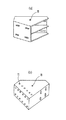
山留め部材としては、例えば、図12(a)に示す如くの火打ち受ピースや同図(b)に示す隅部受ピース等があり、これらの山留め部材は通常100〜200kgの重量を有するため、人手による積み卸しは困難であり、従って、クレーン等の重機を使用するのが一般的である。つまり、図12に示すように、山留め部材には種類を問わず必ずボルト孔等の透孔11が穿設されているので、この透孔11にワイヤーやシャックルを係止させ、これをクレーンのフックに引っ掛けることにより、吊り上げることができ、容易に荷積み、荷卸しを行うことができる。
【0004】
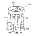
ところが、図12に示した如くの山留め部材は一つの作業現場で多数使用するので、トラックにて一度に多数の山留め部材を輸送することが多く、このため、100〜200kg程度の山留め部材を1個づつクレーンにて吊持して積み卸しを行うことは、数トン〜数十トンの吊り上げ能力を有するクレーンにとっては非常に効率が悪い。そこで、従来より、図13に示す如くの吊り金具101を使用して、クレーンによる1回の吊り上げで複数の山留め部材を同時に吊持して積み卸しする方法が採用されている。
【0005】
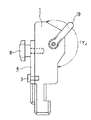
同図に示すように、この吊り金具101は、リング状のフレーム102の周囲に略等間隔で複数本(例えば、10本)のワイヤー(索条体)103を係止させ、更に、このワイヤー103の先端にフック104を固定し、該フック104の先端を図12に示した山留め部材の透孔11内部に挿入して係止することにより吊り上げるものである。図14はフック104の形状を詳細に示す説明図であり、図示のように、このフック104は丸棒の一端部がリング状に形成され、他端部は直角よりもやや鋭角的に且つ滑らかに屈曲された形状を成している。
【0006】
しかしながら、このようなフック104を使用して山留め部材を係止する方法では、山留め部材の固定が確実では無い。即ち、吊り上げの際のバランスが悪い場合や、吊り上げている山留め部材どうしが接触した場合等には、山留め部材がフック104から外れてしまうことがあり、このような場合には山留め部材が落下してしまうので非常に危険である。
【0007】
【発明が解決しようとする課題】
上記したように、従来における山留め部材の吊持用のフック104においては、山留め部材の透孔11に挿入することにより容易に係止することができるものの、固定が確実では無く、バランスを崩したり山留め部材どうしが接触した場合には落下してしまうことがあり、非常に危険であるという問題が発生していた。
【0008】
この発明はこのような従来の課題を解決するためになされたものであり、その目的とするところは、容易且つ確実に山留め部材を係止することのできる山留め部材吊持用冶具を提供することにある。
【0009】
【課題を解決するための手段】
上記目的を達成するため、本願請求項1に記載の発明は、重機のフックに係止された索条体の先端に取り付けられる山留め部材吊持用冶具において、下端部に鈎型形状の鍔部を具えた挿入部を有し、上側適所に吊持用透孔が穿設された掛け止め部材と、前記掛け止め部材の背面側に摺動可能に取り付けられ、中央部に長孔を有し、下部に細棒形状の突起部が形成された摺動杆と、前記摺動杆を掛け止め部材に対し適宜位置に固定するため前記長孔を通して前記掛け止め部材の背面側に前記摺動杆を固定可能な締付ボルトと、から成り、前記挿入部を山留め部材の透孔内に挿入して前記鈎型形状の鍔部を係止させ、次いで、前記摺動杆を長孔に沿って下方向にスライドさせ、透孔の隙間部分に突起部を挿入した後、前記締付ボルトにて固定することにより、山留め部材に固定可能としたことが特徴である。
【0010】
また、請求項2に記載の発明は、重機のフックに係止した索条体の先端に取り付けられる山留め部材吊持用冶具において、下端部に鈎型形状の鍔部を具えた挿入部を有し、上側適所に吊持用透孔が穿設された掛け止め部材と、前記掛け止め部材の背面側に摺動可能に取り付けられ、中央部に長孔を有し、下部に細棒形状の突起部が形成され、且つ、掛け止め部材とはスプリングにより連結され、該スプリングにより常時下方向に付勢される摺動杆と、前記摺動杆を掛け止め部材に対し適宜位置に固定するため前記長孔を通して前記掛け止め部材の背面側に前記摺動杆を固定可能な締付ボルトと、前記摺動杆から略直角方向に突起して配置される操作片と、から成り、前記摺動杆を上方向にスライドさせた状態で、前記掛け止め部材の挿入部を山留め部材の透孔内に挿入して鈎型形状の顎部を係止させ、次いで、前記スプリングの付勢力により前記摺動杆を長孔に沿って下方向にスライドさせ、透孔の隙間部分に前記突起部を挿入することにより、前記山留め部材に対して固定可能としたことを特徴とする。請求項3に記載の発明は、前記摺動杆の両側部には、前記掛け止め部材側に突起して左右方向へのブレを防止するガイド部材が形成されたことを特徴とする。
【0011】
上述の如く構成された本願請求項1に記載の山留め部材吊持用冶具によれば、掛け止め部材の下端部に形成された鈎型形状の挿入部を山留め部材の透孔内部に挿入させ、鈎型形状部分を透孔に引っ掛けた後、摺動杆を下方向にスライドさせて締付ボルトにて固定することにより当該吊持用冶具と山留め部材とを堅固に固定している。従って、吊持用冶具を簡単な操作で容易に山留め部材に取り付けることができ、また、締付ボルトによる固定を解除して摺動杆を上方向にスライドさせない限り、吊持用冶具と山留め部材とは離脱しないので、吊り上げ時の振動や異物との接触による衝撃により落下する等の危険を回避することができる。また、締付ボルトによる固定を解除して、摺動杆を上方向にスライドさせることにより容易に吊持用冶具を山留め部材から取り外すことができるので、作業性が良い。
【0012】
請求項2に記載の山留め部材によれば、スプリングの付勢力により摺動杆が下方向にスライドするように動作するので、作業者は操作片をつかんで摺動杆を上方向にスライドさせ、掛け止め部材の下端部を山留め部材の透孔内に挿入した後、手を離すと摺動杆の先端突起部が透孔内部に挿入されることになり、より一層作業性を向上させることができるようになる。更に、請求項3に記載の発明によれば、ガイド部材により掛け止め部材に対して摺動杆が左右方向にブレることが無いので、摺動杆の挿入を円滑に行うことができるようになる。
【0013】
【発明の実施の形態】
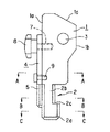
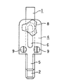
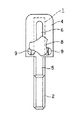
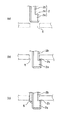
以下、本発明の実施形態を図面に基づいて説明する。図1は、本発明が適用された山留め部材吊持用冶具に係る第1の実施形態の構成を示す側面図、図2は同正面図を示しており、各図に示されるように、この山留め部材吊持用冶具は、下端に鈎型形状の挿入部2が形成され、且つ上方にはシャックルやワイヤーを係止するための透孔3が穿設された掛け止め部材1と、該掛け止め部材1の背面1aに対して摺動可能に取り付けられ、下部に細棒形状の突起部5が形成され、且つ中央部に長孔6が穿設された摺動杆4と、長孔6に挿通され且つ掛け止め部材1の背面1a適所に形成されたネジ孔7に対して螺合される締付ボルト8から構成されている。
【0014】
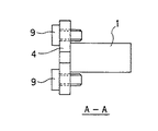
また、図2に示されるように、摺動杆4の中央両側部にはガイドボルト9がそれぞれ螺合して固定されており、点付け溶接により緩みが生じないように固定されている。そして、図3のA−A断面図に示されるように、ガイドボルト9により摺動杆4が掛け止め部材1に対して左右にブレないようにガイドされている。
【0015】
掛け止め部材1は、例えば厚さ16mmの金属プレートを加工して作成されるものであり、図1に示されるように、上端部には背面部1a側から前面部1b側に向けてテーパ状の切り欠き1cが形成されている。また、下端に形成された挿入部2は、幅広部2aと狭窄部2bとにより鈎型形状に構成され、後述するように山留め部材の透孔内部に挿入することができるようになっている。幅広部2aの断面は、図4(a)に示されるように長方形の4隅がカットされた形状とされ、一般的な山留め部材の透孔11のサイズである直径25mmの孔にスムーズに挿入できる大きさ、形状とされている。また、同図(b)に示されるように、狭窄部2bの断面もまた長方形の4隅をカットした形状をなし、更に、摺動杆4の突起部5は長方形の2隅がカットされた形状をなし、これらが連接された状態で、丁度直径25mmの透孔11にスムーズに挿入できる大きさ、形状とされている。
【0016】
締付ボルト8は、作業者による手動操作で容易に回転させることができるものであり、摺動杆4に形成された長孔6を貫通して、掛け止め部材1の背面1aに螺設されたネジ孔7に螺合させることができるものである。即ち、長孔6に沿って摺動杆4を上下方向にスライドさせ、所望の位置で締付ボルト8を回転させて締め付ければ、この位置で摺動杆4を掛け止め部材1に固定させることができる。
【0017】
次に、上記の如く構成された本実施形態の作用について説明する。図1、図2に示した山留め部材吊持用冶具は図13に示した吊り金具101の各ワイヤー103先端部にそれぞれ係止し、各吊持用冶具に山留め部材を固定することにより、重機による1回の吊り上げ作業で複数個の山留め部材を吊り上げることができるものである。そして、まず吊り上げの準備として、掛け止め部材1の透孔3にシャックルを取り付け、これを図13に示した吊り金具101のワイヤー103先端に係止する。
【0018】
次いで、図1、図2に示す締付ボルト8を緩めた状態で摺動杆4を上方向にスライドさせ(図5参照)、この状態で挿入部2を山留め部材に穿設される透孔11内(図12参照)に挿入する。これを、図6に示す模式図を参照しながら説明すると、まず、同図(a)に示すように挿入部2先端の幅広部2aを透孔11内に挿通させ、ある程度挿入された状態で横方向にスライドさせることにより同図(b)に示す如く、鍔部2cを透孔11の周囲部に係止させる。すると、挿入部2の背面側に隙間が生じるので同図(c)に示すように摺動杆4の突起部5を下方向にスライドさせてこの隙間部分に挿入し、透孔11内全体を埋める。
【0019】
次いで、この状態で図1,図2に示した締付ボルト8を締め付けることにより摺動杆4を固定すると、鍔部2cが透孔11に係止された状態が維持されるので、結果として掛け止め部材1に山留め部材が係止されることになる。従って、この状態で前記した吊り金具101(図13参照)を重機により吊り上げれば容易に複数の山留め部材を同時に吊り上げることができる。また、この吊持用冶具に取り付けられた山留め部材は締付ボルト8により堅固に固定され、たとえ吊り上げ時にバランスを崩したり、異物と衝突した場合においても締付ボルト8を緩めて摺動杆4の突起部5を上方にスライドさせない限り、吊持用冶具から外れることは無いので落下の危険が無く安全である。また、吊り上げの作業が終了し、山留め部材から冶具を取り外す際には、締付ボルト8を緩めた後、摺動杆4を上方向にスライドさせれば幅広部2aを透孔11から抜き取ることができるので、簡単に取り外すことができ、作業性が良い。
【0020】
このようにして、本実施形態に係る山留め部材吊持用冶具によれば、掛け止め部材1の下端に形成された挿入部2を山留め部材に穿設された透孔11に挿入して鍔部2cに係止した後、透孔11の隙間部分に摺動杆4の突起部5を挿入し、締付ボルト8を締め付けることにより山留め部材に当該吊持用冶具を固定しているので、取り付け作業が容易で、且つ固定が確実であるから落下等の危険が無く安全である。また、取り外しの作業においても締付ボルト8を緩めて摺動杆4を上方にスライドさせることにより簡単に取り外すことができる。
【0021】
更に、掛け止め部材1の上端部には、テーパ状の切り欠き1cが形成されており、透孔11に取り付けられるシャックルがこの切り欠き1cに接触してこれ以上の回転が阻止されるので、シャックルが締付ボルト8に接触することは無く、締付ボルト8を損傷することは無い。即ち、図7に示されるように透孔3に係止されたシャックル19は図中矢印「Y」の範囲でのみ回転移動することができるので、シャックル19が締付ボルト8に接触することは無い。
【0022】
また、摺動杆4に取り付けられた2個のガイドボルト9(図3参照)により、該摺動杆4は掛け止め部材1に対して左右方向にブレることは無く、容易に摺動杆4の先端部5を透孔11に挿入することができる。なお、本実施形態ではガイド部材としてガイドボルト9を例に説明したが、本発明はこれに限定されるものでは無い。つまり、上記したようにガイド部材は摺動杆4が掛け止め部材1に対して左右方向にブレることを防止するために取り付けるものであるから、例えば、溶接により摺動杆4にプレートを固定して左右のブレを防止する方法を用いても良く、種々の変形が可能である。
【0023】
更に、図1、図2から明らかなように、本実施形態に係る山留め部材吊持用冶具を構成する各種部品(掛け止め部材1、摺動杆4)は、金属製のプレートを適宜切断加工することにより容易に加工することができ、また、締付ボルト8は既存のものをそのまま使用することができるので、製作が容易でありコスト的に安価であるという利点を有する。
【0024】
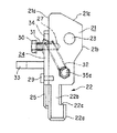
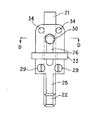
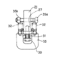
次に、本発明の第2の実施形態について説明する。図8は第2の実施形態に係る山留め部材吊持用冶具の構成を示す側面図、図9は同正面図、図10は図9におけるA−A断面図であり、図示のようにこの吊持用冶具は、前記した第1の実施形態にて示したものとほぼ同様であるが、スプリング32の付勢力を利用して摺動杆24を下方向にスライドさせる点で異なっている。即ち、本実施形態の山留め部材吊持用冶具は、掛け止め部材21と、この掛け止め部材21の背面側21aに摺動可能に接触する摺動杆24と、この摺動杆24を上下方向に移動させるための操作片33とを有して構成され、掛け止め部材21の略中央部には該掛け止め部材21の面に対して直交する方向にボルト35aが挿通され(図10参照)、この先端部にはナット35bが螺合されている。一方、摺動杆24の上端部には左右両側に透孔34が穿設されており(図9参照)、ボルト35aと透孔34との間には2本の引っ張りバネ32が連結されている。また、摺動杆24に穿設された長孔26を貫通して掛け止め部材21の背面21aに形成されたネジ孔27に螺合するボルト30が取り付けられ、このボルト30と摺動杆24との間には圧縮バネ31が配置されて、該圧縮バネ31の付勢力により摺動杆24が掛け止め部材21の背面21a側に押し付けられている。また、操作片33は図10に示されるようにU字形状を成しており、この中央空間部を利用してボルト30との接触を回避している。
【0025】
また、第1の実施例と同様に、摺動杆24の適所にガイドボルト29を2個取り付けることにより、掛け止め部材21に対して摺動杆24が左右にブレることが無いようにされている。
【0026】
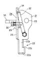
次に、第2の実施形態に係る作用について説明する。この吊持用冶具を使用して山留め部材を吊り上げる際には、前記した第1の実施形態と同様に、まず吊り上げの準備として透孔23にシャックルを係止させ、該シャックルを図13に示した吊り金具101のワイヤー103先端に連結する。そして、この状態で、作業者は操作片33を指でつまんで上方向に持ち上げると、スプリング32の付勢力に抗して摺動杆24は上方向にスライドし、図11に示す如く、スプリング32が伸びきった状態とされる。
【0027】
次いで、図6に示した手順と同様に、挿入部22の幅広部22aを山留め部材の透孔11に挿入し、鍔部22cを透孔11の周囲部に引っ掛けた状態で、図8,図9に示す操作片33から手を離すと、スプリング32の引っ張り力により摺動杆24は下方向にスライドされ、図6(c)に示した状態と同様に透孔11内全体が埋められ、山留め部材と当該吊持用冶具とが固定される。
【0028】
従って、前記した第1の実施形態と同様に簡単な操作で吊持用冶具と山留め部材とを固定することができ、スプリング32の付勢力に抗して摺動杆24を上方向にスライドさせない限り両者は離脱しないので、安全である。また、スプリング32の付勢力により摺動杆24がスライドされる構成であるから、締付ボルト8を使用する第1の実施形態と比較してより一層操作性が向上する。また、取り外しの際には、操作片33をつかんで摺動杆24を上方向にスライドさせれば容易に挿入部22を透孔11から取り外すことができるので作業性が良い。更に、第1の実施形態と同様に、掛け止め部材21の上面にはテーパ状の切り欠き21cが形成されているので、シャックルを取り付けた際に、該シャックルがボルト30や操作片33に接触することは無く、損傷するという問題は発生しない。また、ガイドボルト29により、摺動杆24が掛け止め部材21に対して左右方向にブレることを防止することができる。
【0029】
更に、前記した第1の実施形態と同様に、掛け止め部材21、摺動杆24等の各種部品は、金属製のプレートを適宜切断加工することにより容易に製作することができるので、コスト的に安価である。
【0030】
【発明の効果】
以上説明したように、本発明の山留め部材吊持用冶具では、掛け止め部材の下端部に形成される鈎型形状部を山留め部材の透孔に挿入した後、透孔の隙間部分に摺動杆の先端部を挿入することにより、山留め部材と吊持用冶具とを固定しているので、着脱が容易であり、且つ、吊り上げ時に山留め部材が外れることが無く安全である。従って、重機による一度の吊り上げ作業にて複数個の山留め部材を移動させる作業をより安全且つ容易に行うことができるようになる。
【0031】
また、本発明の山留め部材吊持用冶具は、金属製のプレートを切断加工することにより容易に各種部品を製作することができるので、製作が容易にであり、且つコストダウンを図ることができるという効果を得ることができる。
【図面の簡単な説明】
【図1】本発明の第1の実施形態に係る山留め部材吊持用冶具の構成を示す側面図。
【図2】本発明の第1の実施形態に係る山留め部材吊持用冶具の構成を示す正面図。
【図3】図1におけるA−A断面図。
【図4】(a)は図1におけるC−C断面図、(b)は図1におけるB−B断面図。
【図5】摺動杆を上側にスライドさせた様子を示す説明図。
【図6】挿入部を山留め部材の透孔内部に挿入する様子を示す説明図であり、(a)は幅広部を挿入する様子を示し、(b)は鍔部を透孔に係止した様子を示し、(c)は摺動杆の先端部を透孔内部に挿入した様子を示している。
【図7】第1の実施形態に係る山留め部材吊持用冶具にシャックルを係止した様子を示す説明図。
【図8】本発明の第2の実施形態に係る山留め部材吊持用冶具の構成を示す側面図。
【図9】本発明の第2の実施形態に係る山留め部材吊持用冶具の構成を示す正面図。
【図10】図9におけるD−D断面図。
【図11】スプリングを付勢させて摺動杆を上方向にスライドさせた様子を示す説明図。
【図12】一般的な山留め部材の構成を示す斜視図。
【図13】吊持用金具の構成を示す斜視図。
【図14】吊持用金具のワイヤー先端部に取り付けられるフックの従来例を示す説明図。
【符号の説明】
1、21 掛け止め部材
1a、21a 背面
1b、21b 前面
1c、21c 切り欠き
2、22 挿入部
2a、22a 幅広部
2b、22b 狭窄部
2c、22c 鍔部
3、23 透孔
4、24 摺動杆
5、25 突起部
6、26 長孔
7、27 ネジ孔
8 締付ボルト
9 ガイドボルト
11 透孔
19 シャックル
30 ボルト
31 圧縮バネ
32 引っ張りバネ
33 操作片
34 透孔
35a ボルト
35b ナット[0001]
BACKGROUND OF THE INVENTION
The present invention relates to a jig for suspending a mountain retaining member that is used when simultaneously suspending a plurality of mountain retaining members by one lifting with a crane, and in particular, it is easy to attach and detach, and to securely fix the mountain retaining member. It relates to technology that can be used.
[0002]
[Prior art]
In general, at the excavation site in a mountain retaining work, work is carried out using a large number of main retaining members and retaining members, and these main retaining members and retaining members are loaded onto a truck from a production factory or a storage warehouse. It is transported to the site and unloaded. Further, after the work is completed, the used main retaining material and retaining member are loaded onto a truck and transported to another work site or a storage facility such as a warehouse.
[0003]
As the retaining member, for example, there is a fire receiving piece as shown in FIG. 12 (a), a corner receiving piece as shown in FIG. 12 (b), etc., and these retaining members usually have a weight of 100 to 200 kg, Manual loading and unloading is difficult, and it is common to use heavy machinery such as cranes. That is, as shown in FIG. 12, since the mountain retaining member is always provided with a through-
[0004]
However, since a large number of retaining members as shown in FIG. 12 are used at one work site, a large number of retaining members are often transported at once in a truck. For this reason, a retaining member of about 100 to 200 kg is often used. It is very inefficient for a crane having a lifting capacity of several tons to several tens of tons to be lifted and unloaded by individual cranes. Therefore, conventionally, a method has been employed in which a plurality of retaining members are simultaneously lifted and unloaded by a single lifting by a crane using a suspension fitting 101 as shown in FIG.
[0005]
As shown in the figure, the hanging metal fitting 101 has a plurality of (for example, ten) wires (strands) 103 locked around the ring-shaped
[0006]
However, in the method of locking the mountain retaining member using such a
[0007]
[Problems to be solved by the invention]
As described above, the
[0008]
The present invention has been made to solve such conventional problems, and an object of the present invention is to provide a jig for suspending a mountain retaining member capable of easily and reliably locking the mountain retaining member. It is in.
[0009]
[Means for Solving the Problems]
To achieve the above object, the invention according to the
[0010]
According to a second aspect of the present invention, there is provided a jig for suspending a mountain retaining member attached to the tip of a cable body locked to a hook of a heavy machine, wherein an insertion portion having a hook-shaped hook at the lower end is provided. A latching member with a through hole for suspension at an appropriate position on the upper side, a slidably attached to the back side of the latching member , a long hole at the center , and a thin rod shape at the bottom The protrusion is formed, and is connected to the latch member by a spring, and a sliding rod that is constantly urged downward by the spring, and the sliding rod is fixed to the latch member at an appropriate position. For this purpose , the sliding rod comprises a fastening bolt capable of fixing the sliding rod to the back side of the latching member through the elongated hole, and an operation piece arranged to project from the sliding rod in a substantially right angle direction. With the pallet sliding upward, the insertion part of the latch member Is inserted into the through hole of the fastening member is engaged with jaw hook shape, then slide down the sliding rod along the long hole by the urging force of the spring, the through hole gap portion inserting the protruding portion by, characterized in that the fixable relative to the earth retaining member. The invention described in
[0011]
According to the mountain-clamping member lifting jig according to
[0012]
According to the mountain retaining member of
[0013]
DETAILED DESCRIPTION OF THE INVENTION
Hereinafter, embodiments of the present invention will be described with reference to the drawings. FIG. 1 is a side view showing a configuration of a first embodiment of a jig for suspending a mountain retaining member to which the present invention is applied, and FIG. 2 shows the same front view. As shown in each figure, The jig for suspending the mountain retaining member includes a
[0014]
Further, as shown in FIG. 2, guide
[0015]
The
[0016]
The tightening
[0017]
Next, the operation of the present embodiment configured as described above will be described. 1 and 2 is engaged with the tips of the
[0018]
Next, in a state where the tightening
[0019]
Next, when the sliding
[0020]
Thus, according to the jig for suspending the mountain retaining member according to this embodiment, the
[0021]
Further, a taper-shaped notch 1c is formed at the upper end portion of the latching
[0022]
Further, the two guide bolts 9 (see FIG. 3) attached to the sliding
[0023]
Further, as is clear from FIGS. 1 and 2, various components (the retaining
[0024]
Next, a second embodiment of the present invention will be described. 8 is a side view showing the structure of a jig for suspending a mountain retaining member according to the second embodiment, FIG. 9 is a front view of the same, and FIG. 10 is a cross-sectional view taken along the line AA in FIG. The holding jig is substantially the same as that shown in the first embodiment described above, but differs in that the sliding
[0025]
Further, similarly to the first embodiment, by attaching two
[0026]
Next, the operation according to the second embodiment will be described. When lifting the mountain retaining member using this lifting jig, the shackle is first locked in the through-
[0027]
Next, in the same manner as the procedure shown in FIG. 6, the wide portion 22 a of the
[0028]
Therefore, similarly to the first embodiment described above, the lifting jig and the retaining member can be fixed with a simple operation, and the sliding
[0029]
Further, as in the first embodiment described above, various parts such as the latching
[0030]
【The invention's effect】
As described above, in the mountain-clamping member lifting jig according to the present invention, after the hook-shaped portion formed at the lower end portion of the retaining member is inserted into the through-hole of the mountain-clamping member, it slides into the gap portion of the through-hole. By inserting the tip portion of the scissors, the mountain retaining member and the lifting jig are fixed, so that it is easy to attach and detach, and it is safe because the mountain retaining member does not come off during lifting. Therefore, the operation of moving the plurality of retaining members by a single lifting operation by a heavy machine can be performed more safely and easily.
[0031]
Moreover, the jig for suspending the mountain retaining member according to the present invention can easily produce various parts by cutting a metal plate, so that the production is easy and the cost can be reduced. The effect that can be obtained.
[Brief description of the drawings]
FIG. 1 is a side view showing a configuration of a jig for suspending a mountain retaining member according to a first embodiment of the present invention.
FIG. 2 is a front view showing a configuration of a jig for suspending a mountain retaining member according to the first embodiment of the present invention.
3 is a cross-sectional view taken along line AA in FIG.
4A is a cross-sectional view taken along the line CC in FIG. 1, and FIG. 4B is a cross-sectional view taken along the line BB in FIG.
FIG. 5 is an explanatory view showing a state in which the sliding rod is slid upward.
FIGS. 6A and 6B are explanatory views showing a state in which the insertion portion is inserted into the through hole of the mountain retaining member. FIG. 6A shows a state in which the wide portion is inserted, and FIG. (C) has shown the mode that the front-end | tip part of the sliding rod was inserted in the through-hole.
FIG. 7 is an explanatory view showing a state where a shackle is locked to a jig for suspending a mountain retaining member according to the first embodiment.
FIG. 8 is a side view showing the configuration of a jig for hanging a mountain retaining member according to a second embodiment of the present invention.
FIG. 9 is a front view showing a configuration of a jig for hanging a mountain retaining member according to a second embodiment of the present invention.
10 is a cross-sectional view taken along the line DD in FIG. 9. FIG.
FIG. 11 is an explanatory view showing a state in which the spring is urged to slide the sliding rod upward.
FIG. 12 is a perspective view showing a configuration of a general mountain retaining member.
FIG. 13 is a perspective view showing a configuration of a hanging metal fitting.
FIG. 14 is an explanatory view showing a conventional example of a hook attached to a wire tip of a hanging metal fitting.
[Explanation of symbols]
1, 21 Latching members 1a,
9
19
Claims (3)
下端部に鈎型形状の鍔部を具えた挿入部を有し、上側適所に吊持用透孔が穿設された掛け止め部材と、
前記掛け止め部材の背面側に摺動可能に取り付けられ、中央部に長孔を有し、下部に細棒形状の突起部が形成された摺動杆と、
前記摺動杆を掛け止め部材に対し適宜位置に固定するため前記長孔を通して前記掛け止め部材の背面側に前記摺動杆を固定可能な締付ボルトと、から成り、
前記挿入部を山留め部材の透孔内に挿入して前記鈎型形状の鍔部を係止させ、次いで、前記摺動杆を長孔に沿って下方向にスライドさせ、透孔の隙間部分に前記突起部を挿入した後、前記締付ボルトにて固定することにより、山留め部材に固定可能としたことを特徴とする山留め部材吊持用冶具。In the jig for hanging the retaining member attached to the tip of the cable body locked to the hook of the heavy machine,
A latching member having an insertion part having a hook-shaped hook at the lower end, and a through hole for suspension at an appropriate position on the upper side;
A sliding rod that is slidably attached to the back side of the latching member, has a long hole in the center, and has a thin rod-shaped projection formed at the bottom ,
A fastening bolt capable of fixing the sliding rod to the back side of the latching member through the elongated hole in order to fix the sliding rod to an appropriate position with respect to the latching member ;
The insertion portion is inserted into the through hole of the mountain retaining member to lock the hook-shaped hook portion, and then the sliding hook is slid downward along the long hole to form a gap portion of the through hole. A jig for suspending a mountain retaining member, wherein the jig is capable of being fixed to a mountain retaining member by inserting the protruding portion and then fixing with the tightening bolt.
下端部に鈎型形状の鍔部を具えた挿入部を有し、上側適所に吊持用透孔が穿設された掛け止め部材と、
前記掛け止め部材の背面側に摺動可能に取り付けられ、中央部に長孔を有し、下部に細棒形状の突起部が形成され、且つ、掛け止め部材とはスプリングにより連結され、該スプリングにより常時下方向に付勢される摺動杆と、
前記摺動杆を掛け止め部材に対し適宜位置に固定するため前記長孔を通して前記掛け止め部材の背面側に前記摺動杆を固定可能な締付ボルトと、
前記摺動杆から略直角方向に突起して配置される操作片と、から成り、
前記摺動杆を上方向にスライドさせた状態で、前記掛け止め部材の挿入部を山留め部材の透孔内に挿入して鈎型形状の鍔部を係止させ、次いで、前記スプリングの付勢力により前記摺動杆を長孔に沿って下方向にスライドさせ、透孔の隙間部分に前記突起部を挿入することにより、前記山留め部材に対して固定可能としたことを特徴とする山留め部材吊持用冶具。In the jig for hanging the retaining member attached to the tip of the cable body locked to the hook of the heavy machine,
A latching member having an insertion part having a hook-shaped hook at the lower end, and a through hole for suspension at an appropriate position on the upper side;
The latch member is slidably attached to the back side of the latch member, has a long hole in the center portion , has a thin rod-shaped protrusion at the lower portion , and is connected to the latch member by a spring. A sliding rod that is always urged downward by
A fastening bolt capable of fixing the sliding rod to the back side of the latching member through the elongated hole in order to fix the sliding rod to an appropriate position with respect to the latching member ;
An operation piece arranged to protrude in a substantially right angle direction from the sliding rod, and
Said sliding rod in a state of being slid upwards and engaging was locked to the flange portion of the hook-shaped by inserting the insertion portion of the hook stopper member in the through hole of the earth retaining member, then the urging force of the spring It said sliding rod to slide down along the long holes, by inserting the protruding portion into the gap portion of the through hole, hanging Retaining member characterized by being fixable relative to the earth retaining member by Holding jig.
Priority Applications (1)
| Application Number | Priority Date | Filing Date | Title |
|---|---|---|---|
| JP22203297A JP3607052B2 (en) | 1997-08-05 | 1997-08-05 | Hoisting jig |
Applications Claiming Priority (1)
| Application Number | Priority Date | Filing Date | Title |
|---|---|---|---|
| JP22203297A JP3607052B2 (en) | 1997-08-05 | 1997-08-05 | Hoisting jig |
Publications (2)
| Publication Number | Publication Date |
|---|---|
| JPH1149473A JPH1149473A (en) | 1999-02-23 |
| JP3607052B2 true JP3607052B2 (en) | 2005-01-05 |
Family
ID=16776023
Family Applications (1)
| Application Number | Title | Priority Date | Filing Date |
|---|---|---|---|
| JP22203297A Expired - Lifetime JP3607052B2 (en) | 1997-08-05 | 1997-08-05 | Hoisting jig |
Country Status (1)
| Country | Link |
|---|---|
| JP (1) | JP3607052B2 (en) |
Families Citing this family (2)
| Publication number | Priority date | Publication date | Assignee | Title |
|---|---|---|---|---|
| JP5362945B2 (en) * | 2006-03-06 | 2013-12-11 | 大和ハウス工業株式会社 | Hanging jig |
| JP7117952B2 (en) * | 2018-09-12 | 2022-08-15 | 株式会社クボタ | Hand part for holding luggage |
-
1997
- 1997-08-05 JP JP22203297A patent/JP3607052B2/en not_active Expired - Lifetime
Also Published As
| Publication number | Publication date |
|---|---|
| JPH1149473A (en) | 1999-02-23 |
Similar Documents
| Publication | Publication Date | Title |
|---|---|---|
| JP6848142B1 (en) | Cradle | |
| JP3607052B2 (en) | Hoisting jig | |
| JP4225563B1 (en) | Temporary rope stopper when carrying a rope on truck load | |
| JP5913930B2 (en) | Suspension jig for large concrete structures | |
| JP2842274B2 (en) | Corner protector for wire sling | |
| US11148910B1 (en) | Remote release shackle for choker hitch | |
| JP3109069U (en) | Steel hanger | |
| JP2014143871A (en) | Fixture for overhead wire lean-over instrument and method of fixing overhead wire lean-over instrument by using the same | |
| JP6776026B2 (en) | Slinging hand hook stick | |
| CN222374131U (en) | Battery pack lifting hook | |
| KR102329636B1 (en) | Lifting lug for cable winding bobbin | |
| CN215402589U (en) | Anti-falling device for lifting hook and lifting sling | |
| JP7486793B2 (en) | Lifting balance | |
| JPH05172190A (en) | Rope connecting tool | |
| JP4965110B2 (en) | Eye reinforcement bracket | |
| JPH1162251A (en) | Manually holding type hoisting device | |
| JP3146694U (en) | Temporary rope stopper when carrying a rope on truck load | |
| JPS6316713Y2 (en) | ||
| KR20120007300U (en) | Crane jig for trolly beam | |
| JP6673374B2 (en) | Work machine coupling device | |
| JP3888509B2 (en) | Pallet locking bracket | |
| JPH1135273A (en) | Jig for suspending mountain retaining material | |
| JP2607619Y2 (en) | Rope vise | |
| JP5349539B2 (en) | Fall-off prevention device | |
| JP2000264557A (en) | Adjustment jig for elevator main rope end |
Legal Events
| Date | Code | Title | Description |
|---|---|---|---|
| A977 | Report on retrieval |
Free format text: JAPANESE INTERMEDIATE CODE: A971007 Effective date: 20040325 |
|
| A131 | Notification of reasons for refusal |
Free format text: JAPANESE INTERMEDIATE CODE: A131 Effective date: 20040414 |
|
| A521 | Written amendment |
Free format text: JAPANESE INTERMEDIATE CODE: A523 Effective date: 20040610 |
|
| TRDD | Decision of grant or rejection written | ||
| A01 | Written decision to grant a patent or to grant a registration (utility model) |
Free format text: JAPANESE INTERMEDIATE CODE: A01 Effective date: 20040929 |
|
| A61 | First payment of annual fees (during grant procedure) |
Free format text: JAPANESE INTERMEDIATE CODE: A61 Effective date: 20041006 |
|
| R150 | Certificate of patent or registration of utility model |
Free format text: JAPANESE INTERMEDIATE CODE: R150 |
|
| FPAY | Renewal fee payment (event date is renewal date of database) |
Free format text: PAYMENT UNTIL: 20081015 Year of fee payment: 4 |
|
| FPAY | Renewal fee payment (event date is renewal date of database) |
Free format text: PAYMENT UNTIL: 20091015 Year of fee payment: 5 |
|
| FPAY | Renewal fee payment (event date is renewal date of database) |
Free format text: PAYMENT UNTIL: 20101015 Year of fee payment: 6 |
|
| FPAY | Renewal fee payment (event date is renewal date of database) |
Free format text: PAYMENT UNTIL: 20111015 Year of fee payment: 7 |
|
| FPAY | Renewal fee payment (event date is renewal date of database) |
Free format text: PAYMENT UNTIL: 20111015 Year of fee payment: 7 |
|
| FPAY | Renewal fee payment (event date is renewal date of database) |
Free format text: PAYMENT UNTIL: 20121015 Year of fee payment: 8 |
|
| FPAY | Renewal fee payment (event date is renewal date of database) |
Free format text: PAYMENT UNTIL: 20121015 Year of fee payment: 8 |
|
| FPAY | Renewal fee payment (event date is renewal date of database) |
Free format text: PAYMENT UNTIL: 20131015 Year of fee payment: 9 |
|
| R250 | Receipt of annual fees |
Free format text: JAPANESE INTERMEDIATE CODE: R250 |
|
| R250 | Receipt of annual fees |
Free format text: JAPANESE INTERMEDIATE CODE: R250 |
|
| R250 | Receipt of annual fees |
Free format text: JAPANESE INTERMEDIATE CODE: R250 |
|
| R250 | Receipt of annual fees |
Free format text: JAPANESE INTERMEDIATE CODE: R250 |
|
| EXPY | Cancellation because of completion of term |