JP3607045B2 - Railway substation power control equipment - Google Patents
Railway substation power control equipment Download PDFInfo
- Publication number
- JP3607045B2 JP3607045B2 JP17034697A JP17034697A JP3607045B2 JP 3607045 B2 JP3607045 B2 JP 3607045B2 JP 17034697 A JP17034697 A JP 17034697A JP 17034697 A JP17034697 A JP 17034697A JP 3607045 B2 JP3607045 B2 JP 3607045B2
- Authority
- JP
- Japan
- Prior art keywords
- substation
- train
- voltage
- substations
- feeding
- Prior art date
- Legal status (The legal status is an assumption and is not a legal conclusion. Google has not performed a legal analysis and makes no representation as to the accuracy of the status listed.)
- Expired - Fee Related
Links
Images


Landscapes
- Supply And Distribution Of Alternating Current (AREA)
Description
【0001】
【発明の属する技術分野】
本発明は、鉄道電気車に電力を供給する変電所の電力制御を行う鉄道変電所電力制御装置に関する。
【0002】
【従来の技術】
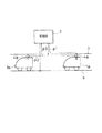
一般に鉄道電気車に電力を供給する変電所設備は、図15に示す構成である。列車1a,1bは変電所2から給電される電力を電車線3、パンタグラフ4a,4bを介して取り込み、走行する(経路p1)。また列車1a,1bは取り込んだ電力をレール5などの帰線を介して変電所2に返還する。さらに最近の列車1a,1bには省エネルギ化を図るために電力回生ブレーキが採用されていて、例えば列車1aが減速する時に発生するエネルギを電力に返還して回生し、この電力を他の列車1bへ供給したり(経路p2)、変電所2に返還して(経路p3)電力の有効利用を図っている。
【0003】
【発明が解決しようとする課題】
このような従来の電気車電力供給設備では、変電所の位置やその他の諸設備の容量は、輸送計画、路線、列車性能などにより割り出されて決定され、それに基づいて運用されているのが現状であり、各変電所から給電されるき電電圧は通常、共通して一定の値の範囲で固定運用されている。一方、運行ダイヤは時間帯によって粗密があり、密ダイヤの時間帯には電力消費量が増大する。
【0004】
ところが変電所の電力は単位時間当たりの電力量で契約する必要があるため、密ダイヤの時間帯に、しかも列車の運行が多少乱れても超えることがない電力量で契約しておく必要があり、実際の平均消費電力量よりも大きな電力量で契約している。また契約電力量を超えた場合にはペナルティが必要であり、これが電力料金を増加させる原因となっている。
【0005】
反面、適切な変電所機器の運用を行わなければき電電圧が低下して列車の定時運行に支障を来すこともある。これに加えて、客扱いなどによる慢性的な列車遅れが発生しやすく、これによって列車の団子状態での運行が発生すると変電所によっては負荷が集中し、き電電圧をいっそう低下させて列車の遅れをさらに大きくする問題点もあった。
【0006】
本発明はこのような従来の問題点に鑑みてなされたもので、多数の列車の運行状態に応じて複数の変電所の使用電力を相互に融通し合うように管理することにより各変電所の使用電力量が可能な限り契約電力量を超えないように適切に制御することができる鉄道変電所電力制御装置を提供することを目的とする。
【0007】
本発明はまた、あらかじめ予想される電力負荷に対して変電所設備を的確に運用することにより、消費電力量の削減と電力供給の安定を図ることができる鉄道変電所電力制御装置を提供することを目的とする。
【0016】
【課題を解決するための手段】
請求項1の発明の鉄道変電所電力制御装置は、列車から送信される走行モード信号を受信する走行モード信号受信手段と、前記走行モード信号受信手段が受信する前記走行モード信号に基づき、複数の変電所それぞれのき電電圧設定値を決定する変電所別き電電圧設定値決定手段と、前記変電所別き電電圧設定値決定手段の決定するき電電圧が得られるように前記複数の変電所それぞれのき電電圧を操作するき電電圧調整手段とを備えたものである。
【0017】
請求項1の発明の鉄道変電所電力制御装置では、走行モード信号受信手段が列車からの走行モード信号を受信し、変電所別き電電圧設定値決定手段がこの列車からの走行モード信号に基づき、力行モード列車が多数存在する給電区間に対しては変電所のき電電圧設定値を大きくし、力行モード列車が少ない給電区間に対しては変電所のき電電圧設定値を小さくし、これらのき電電圧設定値が得られるようにき電電圧調整手段が複数の変電所それぞれのき電電圧を操作する。
【0018】
これにより、力行モード列車が集中するような給電区間のき電電圧を一時的に高くして必要電力をまかない、かつ全体として電力消費を抑える。
【0019】
請求項2の発明の鉄道変電所電力制御装置は、列車が走行する時に通常よりも大きなき電電圧が必要となる特定区間の手前位置に設置され、列車通過を検知する列車通過検知手段と、前記列車通過検知手段が列車通過を検知した時に、特定の変電所のき電電圧設定値を変更するき電電圧設定値変更手段とを備えたものである。
【0020】
請求項2の発明の鉄道変電所電力制御装置では、列車が走行する時に通常よりも大きなき電電圧が必要となる特定区間の手前位置に設置されている列車通過検知手段が列車通過を検知すると、き電電圧設定値変更手段が列車の存在する給電区間のき電電圧設定値を変更する。
【0021】
これにより、例えば勾配の急な線路区間に列車が進入した場合には、その給電区間の電圧を一時的に上昇させて列車が必要とする電力を供給し、平時にはき電電力消費を抑えつつも必要に応じて大電力の供給も可能とする。
【0025】
請求項3の発明の鉄道変電所電力制御装置は、隣接する複数の変電所それぞれの電力量を単位時間ごとに積算する変電所別の単位時間積算電力量演算手段と、前記変電所別の単位時間積算電力量演算手段の算出する前記変電所別の単位時間積算電力量に基づき、前記複数の変電所それぞれのき電電圧設定値を決定する変電所別き電電圧設定値決定手段と、列車が走行する時に通常よりも大きなき電電圧が必要となる特定区間の手前位置に設置され、列車通過を検知する列車通過検知手段と、前記列車通過検知手段が列車通過を検知した時に、前記変電所別き電圧設定値決定手段が決定した変電所別電圧設定値のうち、特定の変電所のき電電圧設定値を変更するき電電圧設定値変更手段と、前記変電所別き電電圧設定値決定手段及び前記き電電圧設定値変更手段の決定するき電電圧が得られるように前記複数の変電所それぞれのき電電圧を操作するき電電圧調整手段とを備えたものである。
【0026】
請求項3の発明の鉄道変電所電力制御装置では、変電所別き電電圧設定値決定手段が変電所別の単位時間積算電力量演算手段の算出する変電所別の単位時間積算電力量に基づいて複数の変電所それぞれのき電電圧設定値を決定し、また列車が走行する時に通常よりも大きなき電電圧が必要となる特定区間の手前位置に設置された列車通過検知手段が列車通過を検知した時に、き電電圧設定値変更手段が変電所別き電圧設定値決定手段の決定した変電所別電圧設定値のうち、特定の変電所のき電電圧設定値を変更し、き電電圧調整手段がこれらの変電所別き電電圧設定値決定手段とき電電圧設定値変更手段とで決定したき電電圧が得られるように複数の変電所それぞれのき電電圧を操作する。
【0027】
これにより、電力消費が大きい変電所には電力消費が小さい変電所から電力を融通し合って、変電所間の消費電力を平均化し、かつ、例えば勾配の急な線路区間に列車が進入した場合には、その給電区間の電圧を上昇させて列車が必要とする電力を供給し、列車速度が特定区間で低下するのを防止する。
【0028】
【発明の実施の形態】
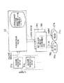
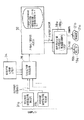
以下、本発明の実施の形態を図に基づいて詳説する。図1〜図3に基づいて本発明の第1の実施の形態を説明する。図1に示すように第1の実施の形態の鉄道変電所電力制御装置のハードウェアは、中央制御室11と、複数のa,b,c,…変電所12a,12b,12c,…と、これらの間の信号伝送路13とで構成されている。
【0029】
中央制御室11は路線若しくは鉄道会社で1つあるいは複数設置される、複数の変電所の電力管理を統括するためのもので、信号伝送路13に対する信号入出力を行う入出力装置14と演算処理を実行する演算装置15を有している。
【0030】
変電所12a,12b,12c,…それぞれは、隣接する2つの給電区間fda,fdb;fdb,fdc;…に所定設定電圧の電力を供給するためのもので、信号伝送路13に対する信号入出力を行う入出力装置16a,16b,16c,…と、消費電力を積算する電力量計17a,17b,17c,…と、変圧器のタップ値と整流器の制御角の操作量を決定する操作量決定部18a,18b,18c,…と、この操作量決定部18a,18b,18c,…により指示される変圧器19a,19b,19c,…のタップ値を操作するタップ値操作部20a,20b,20c,…と、同じく操作量決定部18a,18b,18c,…により指示される整流器21a,21b,21c,…の制御角を操作する制御角操作部22a,22b,22c,…とを有している。
【0031】
図2は第1の実施の形態の鉄道変電所電力制御装置の機能構成を示しており、中央制御室11の演算装置15には演算プログラムとして変電所12a,12b,12c,…分の単位時間積算電力量算出部31a,31b,31c,…と、き電電圧設定値決定部32とが登録されている。そして単位時間積算電力量算出部31a,31b,31c,…は、各変電所12a,12b,12c,…それぞれの電力量計17a,17b,17c,…から入出力装置16−信号伝送路13−入出力装置14を経て送られてくる各変電所ごとの積算消費電力量に基づき、変電所それぞれの単位時間当たりの積算電力量を算出する。またき電電圧設定値決定部32は、この各変電所ごとの単位時間積算電力量データに基づき、後述する方法で変電所12a,12b,12c,…それぞれのき電電圧設定値を決定し、入出力装置14−信号伝送路13−入出力装置16を経て各変電所12a,12b,12c,…の操作量決定部18a,18b,18c,…に送出する。
【0032】
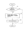
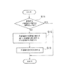
次に、上記の第1の実施の形態の鉄道変電所電力制御装置の動作について説明する。図3は第1の実施の形態において中央制御室11の演算装置15が、き電電圧設定値決定部32によって実行する変電所別き電電圧設定値の決定処理のフローチャートを示している。き電電圧設定値決定部32は、図3のフローチャートに処理を周期的に、例えば、5分周期で繰り返す。
【0033】
それにはまず、単位時間積算電力量算出部31a,31b,…がそれぞれ変電所12a,12b,…の電力計17a,17b,…の消費電力量を取り込み、例えば30分単位の積算消費電力量PWa,PWb,PWc,…を算出してき電電圧設定値決定部32に渡す。
【0034】
そしてき電電圧設定値決定部32では図3のフローチャートに従い、各変電所12a,12b,…の単位時間積算電力量PWa,PWb,PWc,…をあらかじめ設定したしきい値Preと比較する(ステップS1)。ここで単位時間積算電力量PWa,PWb,PWc,…のいずれもがしきい値Pre以内の場合には何もせず、しきい値Preを超えている変電所kがあれば、その変電所kとその両隣の変電所k−1,k+1について、ステップS2の処理に入る。
【0035】
ステップS2では、しきい値Preを超えた変電所kとその両隣の変電所k−1,k+1の単位時間積算電力量を調べ、一方若しくは両方がしきい値を超えていなければ、その1つ若しくは2つの変電所を、き電電圧設定値を引き上げる変電所として決定する。そして、あらかじめ設定してある各変電所のき電電圧変更パラメータaを用いて、次の(1),(2)式でき電電圧設定値を変更する(ステップS2,S3)。
【0036】
【数1】
【0037】
そしてVk*=Vokになった時には、
Vk*=Vok・ (1−ak ) ……(2)
とする。
【0038】
このようにしてき電電圧設定値決定部32が相隣接する3つの変電所k−1,k,k+1の間でき電電圧設定値Vk−1*,Vk*,Vk+1*を決定すると、入力装置14、信号伝送路13を通じて該当する変電所k−1,k,k+1に対してこれらのき電電圧設定値Vk−1*,Vk*,Vk+1*を個別に送信する。
【0039】
新たなき電電圧設定値を受信した変電所、ここではa変電所12aがVk−1*を受信したとすると、入出力装置17aがこの信号を受信し、操作量決定部18aに渡し、操作量決定部18aでは、き電電圧を調整する操作端として変圧器タップ値と整流器制御角があるが、それらの操作量を演算し、タップ値操作部20a、制御角操作部22aに指示し、タップ値操作部20aは変圧器19aのタップ値を指定量だけ操作し、また制御角操作部22aは整流器21aの制御角を指定量だけ操作する。
【0040】
ここで、き電電圧として変圧器19aのタップ値を操作する場合、操作量決定部18aでは、タップ値対二次側電圧表からき電電圧設定値として与えられた電圧値を出力するタップ値を選択し、そのタップ値をタップ値操作部20aに指示する。また整流器制御角についても同様に決定する。
【0041】
これによって、例えば、図1 に示した状態で、真ん中のb変電所12bの単位時間積算電力量がしきい値を超えた場合、この真ん中のb変電所12bのき電電圧を1 段階低下させると共に、給電区間fdbに対しては、左側のa変電所12aのき電電圧を1 段階上昇させることによってb変電所12bの供給電力減少分を補う。そして給電区間fdcに対しては、右側のc変電所12cのき電電圧を1 段階上昇させることによってb変電所12bの供給電力減少分を補う。これによって、電力消費が大きい変電所に対しては、同じ給電区間に給電する隣接変電所からの供給電力量を増加させることによって不足分を補うようにして、変電所間の電力消費を平均化し、1 つの変電所で積算電力量が契約量を超過するのを可能な限り防止する。
【0042】
なお、上記の実施の形態では信号伝送路13に有線のLANを利用したが、これに限らず、中央制御室11と各変電所間は無線通信方式であってもよい。また上記の実施の形態では中央制御室11においてき電電圧設定値決定手段を設けたが、この機能は特に中央制御室11に設置する必要がなく、複数の変電所間を相互に有線または無線の伝送路で結び、いずれかの変電所に上記の実施の形態で説明した中央制御室11の機能を設ける構成とすることもできる。
【0043】
次に、本発明の第2実施の形態を図4及び図5に基づいて説明する。第2の実施の形態の鉄道変電所電力制御装置は、図1に示した第1の実施の形態とハードウェア構成は同じであるが、中央制御室11における演算装置15が、単位時間積算電力量算出部31a,31b,…とき電電圧設定値決定部32と共に、時間帯別の変電所間の列車運転本数データを記憶する時間帯別変電所間列車運転本数記憶部33を有し、き電電圧設定値決定部32が実行する変電所ごとのき電電圧設定値の決定処理においてこの時間帯別変電所間列車運転本数記憶部33のデータを参照して、しきい値を超える単位時間積算電力量を示す変電所に対して負荷を分担させるためにき電電圧を上げる変電所を決定するようにしたことを特徴とする。
【0044】
すなわち、図5のフローチャートに示すように、き電電圧設定値決定部32では各変電所12a,12b,…の単位時間積算電力量PWa,PWb,PWc,…をあらかじめ設定したしきい値Preと比較し(ステップS1)、いましきい値Preを超える変電所kがあれば、その変電所kとその両隣の変電所k−1,k+1について、ステップS2′の処理に入る。
【0045】
ステップS2′では、しきい値Preを超えた変電所kとその両隣の変電所k−1,k+1の単位時間積算電力量を調べ、また時間帯別変電所間列車運転本数記憶部33から現在時刻に対応する時間帯の変電所間列車運転本数データLk−1〜k,Lk〜k+1 を読み出す。そして両隣の変電所k−1,k+1の単位時間積算電力量がいずれもしきい値を超えていなければ、次に基準にしたがって、それらの1つ若しくは両方の変電所をき電電圧設定値を引き上げる変電所として決定する。
【0046】
【数2】
Lk−1〜k <Lk〜k+1 ならば、変電所k−1
Lk−1〜k >Lk〜k+1 ならば、変電所k+1
Lk−1〜k =Lk〜k+1 ならば、両変電所k−1,k+1
そして、これによって決定した変電所k−1,k+1のいずれか一方または両方と、しきい値を超える電力消費がある変電所kに対して、第1の実施の形態と同様に、あらかじめ設定してある各変電所のき電電圧変更パラメータaを用いて、上記の(1),(2)式でき電電圧設定値を変更する(ステップS3)。
とする。
【0047】
このようにしてき電電圧設定値決定部32が相隣接する3つの変電所k−1,k,k+1の間でき電電圧設定値Vk−1*,Vk*,Vk+1*を決定すると、以下、第1の実施の形態と同様に、中央制御室11から該当する変電所k−1,k,k+1に対してき電電圧設定値Vk−1*,Vk*,Vk+1*を送信し、各変電所では変圧器タップ値と整流器制御角を所定量だけ操作し、き電電圧設定値を増減調整する。
【0048】
これによって、第1の実施の形態と同様に電力消費が大きい変電所に対しては、同じ給電区間に給電する隣接変電所からの供給電力量を増加させることによって不足分を補うようにして、変電所間の電力消費を平均化し、1 つの変電所で積算電力量が契約量を超過するのを可能な限り防止することができ、その上、負荷分担を行う変電所を決定する際に列車通過本数が少なく、したがってその後にかかる負荷が小さい方に負荷分担させるようにしたので、負荷分担を強いられた変電所がすぐにしきい値を超える積算電力量を示すようになることが少なく、き電電圧設定値の変更処理機会が少なくて済む。
【0049】
なお、上記の第2の実施の形態でも信号伝送路13に有線のLANを利用したが、これに限らず、中央制御室11と各変電所間は無線通信方式であってもよい。また上記の実施の形態では中央制御室11においてき電電圧設定値決定手段を設けたが、この機能は特に中央制御室11に設置する必要がなく、複数の変電所間を相互に有線または無線の伝送路で結び、いずれかの変電所に上記の実施の形態で説明した中央制御室11の機能を設ける構成とすることもできる。
【0050】
さらに第2の実施の形態では、時間帯別変電所間列車運転本数記憶部33のデータに基づいて、しきい値を超えた変電所の負荷分担のためにしきい値を上昇させる変電所を決定したが、この時間帯別変電所間列車運転本数データは各変電所の積算電力量設定値決定の際に利用することもできる。
【0051】
次に、本発明の第3の実施の形態を図6に基づいて説明する。第3の実施の形態の鉄道変電所電力制御装置は、図1のシステムにおける中央制御室11における演算装置15が、図6に示す機能構成を有することを特徴とする。すなわち、単位時間積算電力量算出部31a,31b,…と共に、変電所12a,12b,…ごとの電力量設備定格値Pta,Ptb,…を記憶する変電所別定格値記憶部34と、単位時間積算電力量算出部31a,31b,…からの変電所ごとの単位時間積算電力量PWa,PWb,…と変電所別定格値記憶部34から読み出した変電所別電力量定格値Pta,Ptb,…との比Ra,Rb,…を算出する使用電力量比算出部35を追加的に備えている。そして、き電電圧設定値決定部32では、制御周期ごとに使用電力量比を隣接する変電所間で比較し、均一になるように各変電所のき電電圧設定値を変更するようにしたことを特徴とする。
【0052】
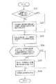
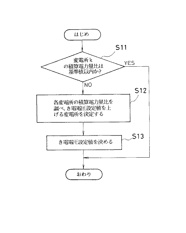
この第3の実施の形態では、演算装置15におけるき電電圧設定値決定部32が図7のフローチャートに示す変電所別き電電圧設定値の決定処理を、例えば、5分周期で繰り返す。
【0053】
それにはまず、単位時間積算電力量算出部31a,31b,…がそれぞれ変電所12a,12b,…の電力計17a,17b,…の消費電力量を取り込み、30分単位の積算消費電力量PWa,PWb,PWc,…を算出し、さらに使用電力量比算出部35が単位時間積算電力量算出部31a,31b,…からの変電所ごとの単位時間積算電力量PWa,PWb,…と変電所別定格値記憶部34から読み出した変電所別電力量定格値Pta,Ptb,…との比Ra,Rb,…を算出してき電電圧設定値決定部32に渡す。
【0054】
そしてき電電圧設定値決定部32では図7のフローチャートに従い、各変電所12a,12b,…の使用電力量比Ra,Rb,…をあらかじめ設定した基準値Rreと比較する(ステップS11)。ここで使用電力量比Ra,Rb,…のいずれもが基準値値Rre以下の場合には何もせず、基準値Rreを超えている変電所kがあれば、その変電所kとその両隣の変電所k−1,k+1について、ステップS12の処理に入る。
【0055】
ステップS12では、基準値Rreを超えた変電所kの両隣の変電所k−1,k+1の使用電力量比Rk−1 ,Rk+1 を調べ、一方若しくは両方が基準値Rreを超えていなければ、その1つ若しくは2つの変電所をき電電圧設定値を引き上げる変電所として決定する。そして第1の実施の形態と同様に、あらかじめ設定してある各変電所のき電電圧変更パラメータaを用いて、上記の(1),(2)式でき電電圧設定値を変更する(ステップS13)。
【0056】
このようにしてき電電圧設定値決定部32が相隣接する3つの変電所k−1,k,k+1の間でき電電圧設定値Vk−1*,Vk*,Vk+1*を決定すると、入力装置14、信号伝送路13を通じて該当する変電所k−1,k,k+1に対してこれらのき電電圧設定値Vk−1*,Vk*,Vk+1*を個別に送信する。
【0057】
新たなき電電圧設定値を受信した各変電所では、第1の実施の形態と同様に、変圧器タップ値と整流器制御角を所定量だけ操作し、き電電圧設定値を増減調整する。
【0058】
これによって、変電所設備ごとに定格値が異なっても、使用電力量比に基づいて基準値を超える電力量を使用している変電所に対しては、その両隣の変電所が同じく基準値以内で負荷を分担し、変電所ごとに使用電力量比を平均化し、1 つの変電所の負担が過剰になるのを可能な限り防止することができるようになる。
【0059】
なお、上記の実施の形態でも信号伝送路13に有線のLANを利用したが、これに限らず、中央制御室11と各変電所間は無線通信方式であってもよい。また上記の実施の形態では中央制御室11においてき電電圧設定値決定手段を設けたが、この機能は特に中央制御室11に設置する必要がなく、複数の変電所間を相互に有線または無線の伝送路で結び、いずれかの変電所に上記の実施の形態で説明した中央制御室11の機能を設ける構成とすることもできる。
【0060】
次に、本発明の第4の実施の形態を図8に基づいて説明する。第4の実施の形態の特徴は、第1〜第3の実施の形態の鉄道変電所電力制御装置において、中央制御部11の演算装置15に、図8に示すようにき電電圧設定ずれ算出部36を備えたことを特徴とする。このき電電圧設定ずれ算出部36は、各変電所に設置されているき電電圧検出器23a,23b,…それぞれからき電電圧検出値Vra,Vrb,…を入力し、自身で算出した各変電所ごとのき電電圧設定値Va,Vb,…と比較してき電電圧設定ずれΔVa,ΔVb,…を算出してき電電圧設定値決定部32にフィードバックする。そしてき電電圧設定値決定部32は、このフィードバックされるき電電圧設定ずれΔVa,ΔVb,…を見て、所定基準値、例えば、5%以上のずれが発生している変電所があれば、その変電所に対するき電電圧設定値を設定ずれ分だけ補正して出力する補正機能を持たせている。
【0061】
すなわち、図9に示すフローチャートを実行するのである。この図9のフローチャートでは、き電電圧設定値決定部32が図3のフローチャートに示した第1の実施の形態と同様にして、ステップS3でき電電圧設定値を決定した後、さらに該当する変電所についてき電電圧設定ずれをき電電圧設定ずれ算出部36から読み込み、き電電圧設定値に対して設定ずれを組み込み、最終的なき電電圧設定値として出力する(ステップS4)。
【0062】
これによって、中央制御室11において各変電所の統括的な管理ができ、かつ正確なき電電圧設定と電力制御ができる。
【0063】
なお、このき電電圧設定ずれ算出部36は第2及び第3の実施の形態のき電電圧設定値決定部32に対しても同じように付加することができ、それによって上記第4の実施の形態と同様の効果を得ることができる。
【0064】
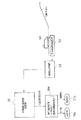
次に、本発明の第5の実施の形態を図10に基づいて説明する。第5の実施の形態の鉄道変電所電力制御装置は、第1の実施の形態と同様に図1に示すハードウェア構成であるが、中央制御室11における演算装置15が図10に示す機能構成であることを特徴とする。
【0065】
すなわち、路線を走行する列車50それぞれには、自車の走行モードが力行モードであるか否かの走行モード信号を列車位置信号と共に送信する走行モード送信装置51が搭載されており、中央制御室11の演算装置15には、この走行モード送信装置51から送られてくる各列車50の列車位置信号及び走行モード信号を受信する走行モード受信部37とこの走行モード受信部37で受信した各列車50からの走行位置と走行モードの情報に基づき、各変電所12a,12b,…のき電電圧設定値を決定して出力するき電電圧設定値決定部32とが備えられている。各列車50の走行モード送信部51と中央制御室11における走行モード受信部37との間の信号送受は、従来から採用されている鉄道無線システムを利用する。
【0066】
この第5の実施の形態の鉄道変電所電力制御装置は、次のように動作する。各列車50の走行モード送信部51が自車位置と走行モードを示す信号を送信すると、中央制御室11における走行モード受信部37が受信してき電電圧設定値決定部32に受け渡す。
【0067】
き電電圧設定値決定部32では、走行モード受信部37が受信した複数の列車50それぞれの走行位置と走行モードとを統括的に分析し、各変電所12a,12b,…ごとの給電区間を走行している力行モードの列車数を割り出し、伝送遅れも考慮しつつ、次のルールに基づいて各変電所のき電電圧設定値を決定する。
【0068】
<ルール1>
ある区間に基準台数A以上、集中して列車が力行している場合には、該当区間のき電電圧をx1%上昇させる。
【0069】
<ルール2>
例えば、勾配が急な区間のような、あらかじめ定められた特定区間を列車が力行中は、該当区間のき電電圧をx2%上昇させる。
【0070】
き電電圧設定値決定部32は、制御周期ごとにこのルールに基づいて各変電所12a,12b,…ごとのき電電圧設定値を算出して入出力装置14、伝送路13を通じて各変電所12a,12b,…に送信する。
【0071】
き電電圧設定値を受信した各変電所12a,12b,…では、第1の実施の形態と同様に、入出力装置17a,17b,…がこの信号を受信し、操作量決定部18a,18b,…に渡し、操作量決定部では、き電電圧を調整する操作端として変圧器タップ値と整流器制御角との必要な操作量を演算し、タップ値操作部20a,20b,…と制御角操作部22a,22b,…に指示し、タップ値操作部20a,20b, …は変圧器19a,19b,…のタップ値を指定量だけ操作し、また制御角操作部22a,22b,…は整流器21a,21b,…の制御角を指定量だけ操作する。
【0072】
これによって、ダイヤの乱れその他の原因である給電区間に負荷が集中するような場合でもき電電圧低下を防止することができる。また勾配が急で加速力が低下するような特定区間での速度低下を防止することもできる。
【0073】
なお、上記の実施の形態でも信号伝送路13に有線のLANを利用したが、これに限らず、中央制御室11と各変電所間は無線通信方式であってもよい。また上記の実施の形態では中央制御室11においてき電電圧設定値決定手段を設けたが、この機能は特に中央制御室11に設置する必要がなく、複数の変電所間を相互に有線または無線の伝送路で結び、いずれかの変電所に上記の実施の形態で説明した中央制御室11の機能を設ける構成とすることもできる。
【0074】
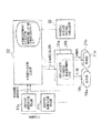
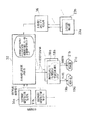
次に、本発明の第6の実施の形態を図11に基づいて説明する。第6の実施の形態の鉄道変電所電力制御装置は、第1の実施の形態と同様に図1に示すハードウェア構成であるが、中央制御室11における演算装置15が図11に示す機能構成である。すなわち、特定区間、特に勾配の急な区間に給電する変電所に対して、列車50がこの特定区間に進入する手前でその列車50を検知してき電電圧設定値を上昇させる制御を行うために、特定区間の手前の地点に列車通過を検知するための列車通過検知装置52を設置し、またこの列車通過検知装置52の列車通過検知信号を中央制御室11に伝送するための情報伝送装置53を備え、中央制御室11の演算装置15には情報伝送装置53から送られてくる列車通過検知信号を入力して、該当する変電所(特に1個所に限定されないが、ここでは、a変電所12aとする)に対するき電電圧設定値をあらかじめ設定した値に変更する指令を出力するき電電圧設定値決定部32を備えたことを特徴とする。
【0075】
列車通過検知装置52と情報伝送装置53には、単純な方法としては所定の位置に設置した光学式、レーザ式、あるいは超音波式センサとこの列車検知信号を中央制御室11まで伝送する信号ケーブルとで構成することができる。また従来から採用されている軌道回路を利用することができる。
【0076】
この第6の実施の形態の鉄道変電所電力制御装置では、列車50が特定区間の手前まで来て、列車通過検知装置52が列車通過を検知すると、情報伝送装置53を通じて中央制御室11に列車通過検知信号が送信される。中央制御室11では、この列車通過検知信号を受信すると、き電電圧設定値決定部32においてあらかじめ設定されている該当する変電所12aに対して一時的にき電電圧設定値を所定量だけ上昇させる指令を送信する。
【0077】
該当する変電所12aでは、このき電電圧設定値変更指令を受けると、第1の実施の形態と同様にして、変圧器19aのタップ値を所定量だけ操作し、また整流器21aの制御角を所定量だけ操作する。
【0078】
この第6の実施の形態では、地方の幹線のように山間部で列車密度が高くないような路線や区間において、簡便な方式で列車の速度維持が図れることになる。また、特定区間を列車通過がした後にはき電電圧設定値を元の値にまで低下させる再設定を行うことにより、速度維持のために常時、き電電圧を高めに設定する必要がなくなり、ランニングコストの低減が図れる。
【0079】
なお、第6の実施の形態では特に、中央制御室11にき電電圧設定値決定部32を設けるのではなく、特定区間への給電を受け持つ変電所12aの操作量決定部18aに列車通過検知装置52の検知信号を直接送信する単純な構成とすることもできる。
【0080】
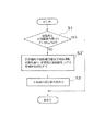
次に、本発明の第7の実施の形態を図12に基づいて説明する。第7の実施の形態の鉄道変電所電力制御装置は、図2に示した第1の実施の形態と図10に示した第5の実施の形態とを組み合わせたことを特徴とする。したがって、通常時には第1の実施の形態と同様に、き電電圧設定値決定部32は、図13のフローチャートに処理を周期的に、例えば、5分周期で繰り返す。
【0081】
き電電圧設定値決定部32では各変電所12a,12b,…の単位時間積算電力量PWa,PWb,PWc,…をあらかじめ設定したしきい値Preと比較し(ステップS21)、いましきい値Preを超える変電所kがあれば、その変電所kとその両隣の変電所k−1,k+1について、ステップS22の処理に入る。
【0082】
ステップS22では、しきい値Preを超えた変電所kとその両隣の変電所k−1,k+1の単位時間積算電力量を調べ、一方若しくは両方がしきい値を超えていなければ、その1つ若しくは2つの変電所をき電電圧設定値を引き上げる変電所として決定する。
【0083】
この後、き電電圧設定値決定部32は、第5の実施の形態で実行した次の処理を行う。走行モード受信部37が受信した複数の列車50それぞれの走行位置と走行モードとを統括的に分析し、各変電所12a,12b,…ごとの給電区間を走行している力行モードの列車数を割り出し、伝送遅れも考慮しつつ、前述したルール1とルール2に基づいて、き電電圧設定値を上昇すべき変電所を決定する(ステップS23)。
【0084】
続いて、ステップS22の処理でき電電圧設定値を低下させるべきと決定した変電所のうち、ステップS23の処理でき電電圧設定値を上昇すべき変電所として決定したものがないかどうか判断し(ステップS24)、該当する変電所があれば、その変電所についてはステップS22でき電電圧設定値を低下させる決定がなされていても元のき電電圧設定値を維持する決定をする(ステップS25)。
【0085】
この後、ステップS26において、第1の実施の形態で説明した(1),(2)式に基づき、また第6の実施の形態で説明したルール1、ルール2に基づいて各変電所のき電電圧設定値を決定する。
【0086】
このようにしてき電電圧設定値決定部32が各変電所12a,12b,…のき電電圧設定値を決定すると、入力装置14、信号伝送路13を通じて各変電所に個別に送信する。そしてき電電圧設定値を受信した各変電所では、き電電圧設定値を現状のき電電圧設定値と比較し、変更が生じていれば、新たに送られてきたき電電圧設定値に一致させるのに必要な操作量を演算し、変圧器19a,19b,…のタップ値と整流器21a,21b,…の制御角を操作する。
【0087】
これによって、例えば、図1 に示した状態で、真ん中のb変電所12bの単位時間積算電力量がしきい値を超えた場合、この真ん中のb変電所12bのき電電圧を1 段階低下させると共に、給電区間fdbに対しては、左側のa変電所12aのき電電圧を1段階上昇させることによってb変電所12bの供給電力減少分を補う。そして給電区間fdcに対しては、右側のc変電所12cのき電電圧を1 段階上昇させることによってb変電所12bの供給電力減少分を補うことができる。
【0088】
しかも、この実施の形態の場合には、真ん中のb変電所12bの給電区間に力行モードの列車が多く存在していて、積算電力量に基づく判断ではき電電圧設定値を下げるべきとされるところが、き電電圧設定値を上昇させる必要がある場合には、該当する変電所12bのき電電圧設定値を元のまま維持することにして、列車運行に支障をきたさない範囲で電力制御する。
【0089】
なお、第7の実施の形態においても第1の実施の形態と同様に、信号伝送路13に有線のLANを利用したが、これに限らず、中央制御室11と各変電所間は無線通信方式であってもよい。また上記の実施の形態では中央制御室11においてき電電圧設定値決定手段を設けたが、この機能は特に中央制御室11に設置する必要がなく、複数の変電所間を相互に有線または無線の伝送路で結び、いずれかの変電所に上記の実施の形態で説明した中央制御室11の機能を設ける構成とすることもできる。
【0090】
次に、本発明の第8の実施の形態を図14に基づいて説明する。第8の実施の形態の鉄道変電所電力制御装置は、図2に示した第1の実施の形態のシステムと図11に示した第6の実施の形態のシステムとを組み合わせた構成を特徴とする。すなわち、き電電圧設定値決定部32は第1の実施の形態と同様の各変電所の単位時間積算電力量を調べて、き電電圧設定値を変更する変電所を決定する。そして、情報伝送装置53から特定区間に対する列車通過検知信号が入力されると、き電電圧設定値決定部32は、該当する変電所に対して第6の実施の形態と同様にき電電圧設定値を所定量だけ上昇させる決定をする。
【0091】
このようにしてき電電圧設定値決定部32が各変電所12a,12b,…のき電電圧設定値を決定すると、入力装置14、信号伝送路13を通じて各変電所に個別に送信する。そしてき電電圧設定値を受信した各変電所では、き電電圧設定値を現状のき電電圧設定値と比較し、変更が生じていれば、新たに送られてきたき電電圧設定値に一致させるのに必要な操作量を演算し、変圧器19a,19b,…のタップ値と整流器21a,21b,…
の制御角を操作する。
【0092】
これによって、第1の実施の形態と同様に電力消費が大きい変電所に対しては、同じ給電区間に給電する隣接変電所からの供給電力量を増加させることによって不足分を補うようにして、変電所間の電力消費を平均化し、1 つの変電所で積算電力量が契約量を超過するのを可能な限り防止することができ、その上、特定区間を列車が通過する時にその速度維持が図れ、かつ通過後にはき電電圧設定値を元の値にまで低下させる再設定を行うことにより、速度維持のために常時、き電電圧を高めに設定する必要がなくなり、ランニングコストの低減が図れる。
【0093】
なお、第8の実施の形態においても第1の実施の形態と同様に、信号伝送路13に有線のLANを利用したが、これに限らず、中央制御室11と各変電所間は無線通信方式であってもよい。また上記の実施の形態では中央制御室11においてき電電圧設定値決定手段を設けたが、この機能は特に中央制御室11に設置する必要がなく、複数の変電所間を相互に有線または無線の伝送路で結び、いずれかの変電所に上記の実施の形態で説明した中央制御室11の機能を設ける構成とすることもできる。
【0097】
【発明の効果】
請求項1の発明によれば、各列車からの走行モード信号に基づき、力行モード列車が多数存在する給電区間に対して変電所のき電電圧設定値を大きくし、力行モード列車が少ない給電区間に対しては変電所のき電電圧設定値を小さくし、これらのき電電圧設定値が得られるように複数の変電所それぞれにおけるき電電圧を操作するので、力行モード列車が集中するような給電区間のき電電圧を一時的に高くして必要電力をまかない、かつ全体として電力消費を抑えることができる。
【0098】
請求項2の発明によれば、例えば勾配の急な線路区間に列車が進入した場合にはその給電区間の電圧を上昇させて列車が必要とする電力を供給し、平時にはき電電力消費を抑えることにより、効率的な電力制御ができる。
【0100】
請求項3の発明によれば、電力消費が大きい変電所には電力消費が小さい変電所から電力を融通し合って変電所間の消費電力を平均化することができ、しかも、例えば勾配の急な線路区間に列車が進入した場合にも速度低下することなく列車を通過させることができる。
【図面の簡単な説明】
【図1】本発明の第1の実施の形態のハードウェア構成のブロック図。
【図2】上記の実施の形態における演算装置部分の機能構成を示すブロック図。
【図3】上記の実施の形態のき電電圧設定値決定部の処理を示すフローチャート。
【図4】本発明の第2の実施の形態の演算装置部分の機能構成を示すブロック図。
【図5】上記の実施の形態のき電電圧設定値決定部の処理を示すフローチャート。
【図6】本発明の第3の実施の形態の演算装置部分の機能構成を示すブロック図。
【図7】上記の実施の形態のき電電圧設定値決定部の処理を示すフローチャート。
【図8】本発明の第4の実施の形態の演算装置部分の機能構成を示すブロック図。
【図9】上記の実施の形態のき電電圧設定値決定部の処理を示すフローチャート。
【図10】本発明の第5の実施の形態の演算装置部分の機能構成を示すブロック図。
【図11】本発明の第6の実施の形態の演算装置部分の機能構成を示すブロック図。
【図12】本発明の第7の実施の形態の演算装置部分の機能構成を示すブロック図。
【図13】上記の実施の形態のき電電圧設定値決定部の処理を示すブロック図。
【図14】本発明の第8の実施の形態の演算装置部分の機能構成を示すブロック図。
【図15】従来例のブロック図。
【符号の説明】
11 中央制御室
12a,12b,… 変電所
13 信号伝送路
14 入出力装置
15 演算装置
16a,16b,… 入出力装置
17a,17b,… 電力計
18a,18b,… 操作量決定部
19a,19b,… 変圧器
20a,20b,… タップ値操作部
21a,21b,… 整流器
22a,22b,… 制御角操作部
23a,23b,… き電電圧検出器
31a,31b,… 単位時間積算電力量算出部
32 き電電圧設定値決定部
33 時間帯別変電所間列車運転本数記憶部
34 変電所別定格値記憶部
35 使用電力量比算出部
36 き電電圧設定ずれ算出部
37 走行モード受信部
50 列車
51 走行モード送信部
52 列車通過検知装置
53 情報伝送装置[0001]
BACKGROUND OF THE INVENTION
The present invention relates to a railway substation power control apparatus that performs power control of a substation that supplies power to a railway electric vehicle.
[0002]
[Prior art]
Generally, a substation facility for supplying electric power to a railway electric vehicle has a configuration shown in FIG. The
[0003]
[Problems to be solved by the invention]
In such conventional electric vehicle power supply facilities, the location of substations and the capacity of other facilities are determined and determined based on transportation plans, routes, train performance, etc. At present, the feeding voltage fed from each substation is usually fixedly operated within a certain range in common. On the other hand, the operation schedule is dense depending on the time zone, and the power consumption increases during the time zone of the dense schedule.
[0004]
However, substations need to be contracted with the amount of power per unit of time, so it is necessary to contract with the amount of power that does not exceed the train schedule even if the train operation is somewhat disturbed. The contract is for a larger amount of power than the actual average power consumption. In addition, a penalty is required when the amount of contracted power is exceeded, which causes an increase in power charges.
[0005]
On the other hand, if the appropriate substation equipment is not operated, the power supply voltage may drop and hinder the regular operation of the train. In addition to this, chronic train delays are likely to occur due to passenger handling, etc., so that when trains are operated in a dumping state, the load is concentrated in some substations, further reducing the feeder voltage and reducing train delays. There was also a problem of making it even larger.
[0006]
The present invention has been made in view of such conventional problems, and by managing the power used by a plurality of substations according to the operating conditions of a large number of trains, each substation can be managed. An object of the present invention is to provide a railway substation power control apparatus that can appropriately control the amount of power used so that it does not exceed the contracted power amount as much as possible.
[0007]
The present invention also provides a railway substation power control device capable of reducing power consumption and stabilizing power supply by appropriately operating substation equipment with respect to a power load expected in advance. With the goal.
[0016]
[Means for Solving the Problems]
The railway substation power control device according to the invention of
[0017]
In the railway substation power control apparatus according to the first aspect of the invention, the travel mode signal receiving means receives the travel mode signal from the train, and the substation-specific power voltage set value determining means is based on the travel mode signal from the train. , Increase the feeding voltage setting value of the substation for the feeding section where there are many power running mode trains, and reduce the feeding voltage setting value of the substation for the feeding section where there are few power running mode trains. The feed voltage adjusting means operates the feed voltage of each of the plurality of substations so that the feed voltage setting value is obtained.
[0018]
As a result, the feeding voltage in the power feeding section where the power running mode trains are concentrated is temporarily increased so as not to cover the necessary power, and the power consumption is suppressed as a whole.
[0019]
The railway substation power control device according to the invention of
[0020]
In the railway substation power control device according to the invention of
[0021]
As a result, for example, when a train enters a track section with a steep slope, the voltage in the power feeding section is temporarily increased to supply the power required by the train, while suppressing power consumption during normal times. In addition, large power can be supplied as required.
[0025]
The railway substation power control device according to the invention of
[0026]
In the railway substation power control apparatus according to the invention of
[0027]
As a result, when substations with high power consumption exchange power from substations with low power consumption, average power consumption between substations, and trains enter, for example, steep track sections In this case, the electric power required by the train is supplied by increasing the voltage in the power feeding section, and the train speed is prevented from decreasing in the specific section.
[0028]
DETAILED DESCRIPTION OF THE INVENTION
Hereinafter, embodiments of the present invention will be described in detail with reference to the drawings. A first embodiment of the present invention will be described with reference to FIGS. As shown in FIG. 1, the hardware of the railway substation power control device according to the first embodiment includes a
[0029]
The
[0030]
Each of the
[0031]
FIG. 2 shows the functional configuration of the railway substation power control apparatus according to the first embodiment. The
[0032]
Next, the operation of the railway substation power control apparatus according to the first embodiment will be described. FIG. 3 shows a flowchart of the process of determining the voltage setting value for each substation executed by the feeding voltage setting
[0033]
First, the unit time integrated power
[0034]
Then, the feeding voltage set
[0035]
In step S2, the unit time integrated electric energy of the substation k exceeding the threshold Pre and its adjacent substations k-1, k + 1 is checked. If one or both do not exceed the threshold, one of them is determined. Alternatively, two substations are determined as substations for raising the feeding voltage set value. Then, using the feeding voltage change parameter a of each substation set in advance, the voltage setting value can be changed according to the following equations (1) and (2) (steps S2 and S3).
[0036]
[Expression 1]
[0037]
And when Vk * = Vok,
Vk * = Vok · (1-ak) (2)
And
[0038]
When the feeder voltage set
[0039]
Assuming that the substation that has received the new feed voltage setting value, in this case, the a
[0040]
Here, when the tap value of the
[0041]
Thus, for example, in the state shown in FIG. 1, when the unit time integrated power amount of the
[0042]
In the above-described embodiment, a wired LAN is used for the
[0043]
Next, a second embodiment of the present invention will be described with reference to FIGS. The railway substation power control apparatus according to the second embodiment has the same hardware configuration as that of the first embodiment shown in FIG. 1, but the
[0044]
That is, as shown in the flowchart of FIG. 5, the feeding voltage set
[0045]
In step S2 ′, the unit time accumulated electric energy of the substation k exceeding the threshold Pre and its adjacent substations k−1 and k + 1 is checked, and the current train number is stored in the inter-substation train operation
[0046]
[Expression 2]
If Lk-1 to k <Lk to k + 1, then substation k-1
If Lk-1 to k> Lk to k + 1, then substation k + 1
If Lk-1 to k = Lk to k + 1, both substations k-1,
Then, in the same manner as in the first embodiment, one or both of the substations k−1 and k + 1 determined thereby and the substation k having power consumption exceeding the threshold value are set in advance. The feeding voltage change parameter a of each substation is used to change the set voltage value according to the above formulas (1) and (2) (step S3).
And
[0047]
When the feeder voltage set
[0048]
As a result, for substations with large power consumption as in the first embodiment, the shortage is compensated by increasing the amount of power supplied from adjacent substations that supply power to the same power supply section. By averaging the power consumption between substations, it is possible to prevent the accumulated power from exceeding the contract amount at one substation as much as possible, and, in addition, trains can be used to determine the substations that share the load. Since the number of passages is small and the load applied thereafter is made smaller, the substations that are forced to share the load are less likely to immediately show the accumulated power exceeding the threshold. Fewer opportunities for changing the voltage setting value.
[0049]
Although the wired LAN is used for the
[0050]
Further, in the second embodiment, based on the data of the train operation
[0051]
Next, a third embodiment of the present invention will be described with reference to FIG. The railway substation power control apparatus according to the third embodiment is characterized in that the
[0052]
In the third embodiment, the feeding voltage set
[0053]
First, the unit time integrated power
[0054]
Then, the feeding voltage set
[0055]
In step S12, the power consumption ratios Rk−1 and Rk + 1 of the substations k−1 and k + 1 adjacent to the substation k exceeding the reference value Rre are checked, and if one or both do not exceed the reference value Rre, One or two substations are determined as substations that raise the feed voltage setting value. Then, as in the first embodiment, using the feeding voltage change parameter a of each substation set in advance, the voltage setting value can be changed according to the above formulas (1) and (2) (step S13).
[0056]
When the feeder voltage set
[0057]
In each substation that has received the new feed voltage setting value, the transformer tap value and the rectifier control angle are manipulated by a predetermined amount to increase or decrease the feed voltage setting value, as in the first embodiment.
[0058]
As a result, even if the rated value differs for each substation facility, for substations that use energy exceeding the standard value based on the power consumption ratio, the adjacent substations are also within the standard value. In this way, it is possible to share the load and average the power consumption ratio for each substation to prevent the burden on one substation from becoming excessive as much as possible.
[0059]
In the above embodiment, a wired LAN is used for the
[0060]
Next, a fourth embodiment of the present invention will be described with reference to FIG. The feature of the fourth embodiment is that, in the railway substation power control device of the first to third embodiments, the
[0061]
That is, the flowchart shown in FIG. 9 is executed. In the flowchart of FIG. 9, after the feeding voltage set
[0062]
As a result, the
[0063]
The feeding voltage setting
[0064]
Next, a fifth embodiment of the present invention will be described with reference to FIG. The railway substation power control apparatus of the fifth embodiment has the hardware configuration shown in FIG. 1 as in the first embodiment, but the
[0065]
That is, each
[0066]
The railway substation power control apparatus according to the fifth embodiment operates as follows. When the traveling
[0067]
The feeding voltage set
[0068]
<
When the train is powering more than the reference number A in a certain section, the feeding voltage in that section is increased by x1%.
[0069]
<
For example, when the train is powering a predetermined specific section such as a section with a steep slope, the feeding voltage of the corresponding section is increased by x2%.
[0070]
The feeding voltage set
[0071]
In each
[0072]
As a result, even when the load is concentrated in the power feeding section, which is a cause of disturbance of the diamond and other causes, it is possible to prevent the feeding voltage drop. Further, it is possible to prevent a decrease in speed in a specific section where the acceleration is reduced due to a steep slope.
[0073]
In the above embodiment, a wired LAN is used for the
[0074]
Next, a sixth embodiment of the present invention will be described with reference to FIG. The railway substation power control device of the sixth embodiment has the hardware configuration shown in FIG. 1 as in the first embodiment, but the
[0075]
As a simple method, the train passing
[0076]
In the railway substation power control apparatus according to the sixth embodiment, when the
[0077]
When the
[0078]
In the sixth embodiment, the train speed can be maintained by a simple method on a route or section where the train density is not high in a mountainous area like a local trunk line. In addition, it is not necessary to set the feeding voltage higher at all times in order to maintain the speed by performing resetting to reduce the feeding voltage setting value to the original value after passing the train through a specific section, Running costs can be reduced.
[0079]
In the sixth embodiment, in particular, the
[0080]
Next, a seventh embodiment of the present invention will be described with reference to FIG. The railway substation power control apparatus according to the seventh embodiment is characterized in that the first embodiment shown in FIG. 2 and the fifth embodiment shown in FIG. 10 are combined. Accordingly, during normal times, as in the first embodiment, the feeding voltage set
[0081]
The feeding voltage set
[0082]
In step S22, the unit time integrated electric energy of the substation k exceeding the threshold Pre and its adjacent substations k-1, k + 1 is checked. If one or both do not exceed the threshold, one of them is determined. Alternatively, two substations are determined as substations that raise the feed voltage setting value.
[0083]
Thereafter, the feeding voltage set
[0084]
Subsequently, it is determined whether or not there is a substation that can be processed in step S22 and that the power voltage set value should be decreased and that the power voltage set value that can be processed in step S23 is determined to be increased ( Step S24) If there is a corresponding substation, the substation is determined to maintain the original feeding voltage setting value even if it has been decided to decrease the voltage setting value in step S22 (step S25). .
[0085]
Thereafter, in step S26, based on the expressions (1) and (2) described in the first embodiment and based on the
[0086]
When the feeder voltage set
[0087]
Thus, for example, in the state shown in FIG. 1, when the unit time integrated power amount of the
[0088]
In addition, in the case of this embodiment, there are many trains in the power running mode in the feeding section of the
[0089]
In the seventh embodiment, a wired LAN is used for the
[0090]
Next, an eighth embodiment of the present invention will be described with reference to FIG. The railway substation power control apparatus according to the eighth embodiment is characterized by a combination of the system according to the first embodiment shown in FIG. 2 and the system according to the sixth embodiment shown in FIG. To do. That is, the feeding voltage set
[0091]
When the feeder voltage set
Manipulate the control angle.
[0092]
As a result, for substations with large power consumption as in the first embodiment, the shortage is compensated by increasing the amount of power supplied from adjacent substations that supply power to the same power supply section. By averaging the power consumption between substations, it is possible to prevent the accumulated power consumption from exceeding the contracted amount at one substation as much as possible, and to maintain the speed when the train passes through a specific section. By resetting to reduce the feeding voltage setting value to the original value after passing, it is not necessary to always set the feeding voltage higher to maintain the speed, reducing the running cost. I can plan.
[0093]
In the eighth embodiment, a wired LAN is used for the
[0097]
【The invention's effect】
According to the invention of
[0098]
According to the second aspect of the present invention, for example, when a train enters a track section with a steep slope, the voltage of the power feeding section is increased to supply the power required by the train, and the power consumption during normal times is reduced. By suppressing, efficient power control can be performed.
[0100]
According to the invention of
[Brief description of the drawings]
FIG. 1 is a block diagram of a hardware configuration according to a first embodiment of this invention.
FIG. 2 is a block diagram showing a functional configuration of an arithmetic device part in the embodiment.
FIG. 3 is a flowchart showing processing of a feeding voltage set value determination unit according to the embodiment.
FIG. 4 is a block diagram showing a functional configuration of an arithmetic device part according to a second embodiment of this invention.
FIG. 5 is a flowchart showing processing of a feeding voltage set value determination unit according to the embodiment.
FIG. 6 is a block diagram showing a functional configuration of an arithmetic unit portion according to a third embodiment of this invention.
FIG. 7 is a flowchart showing processing of a feeding voltage set value determination unit according to the embodiment.
FIG. 8 is a block diagram showing a functional configuration of an arithmetic unit portion according to a fourth embodiment of this invention.
FIG. 9 is a flowchart showing processing of a feeding voltage set value determination unit according to the embodiment.
FIG. 10 is a block diagram showing a functional configuration of an arithmetic unit portion according to a fifth embodiment of the present invention.
FIG. 11 is a block diagram showing a functional configuration of an arithmetic unit portion according to a sixth embodiment of the present invention.
FIG. 12 is a block diagram showing a functional configuration of an arithmetic unit portion according to a seventh embodiment of the present invention.
FIG. 13 is a block diagram showing processing of a feeding voltage set value determination unit according to the embodiment.
FIG. 14 is a block diagram showing a functional configuration of an arithmetic unit according to an eighth embodiment of the present invention.
FIG. 15 is a block diagram of a conventional example.
[Explanation of symbols]
11 Central control room
12a, 12b, ... Substation
13 Signal transmission path
14 I / O devices
15 Arithmetic unit
16a, 16b, ... I / O device
17a, 17b, ... Wattmeter
18a, 18b, ... operation amount determination unit
19a, 19b, ... Transformer
20a, 20b, ... Tap value operation section
21a, 21b, ... Rectifier
22a, 22b, ... Control angle operation section
23a, 23b, ... Feed voltage detector
31a, 31b,... Unit time integrated electric energy calculation unit
32 Feeding voltage set value determination unit
33 Number of train operations between substations by time zone
34 Rated value storage by substation
35 Power consumption ratio calculation part
36 Feed voltage setting deviation calculator
37 Driving mode receiver
50 trains
51 Driving mode transmitter
52 Train passing detector
53 Information transmission equipment
Claims (3)
前記走行モード信号受信手段が受信する前記走行モード信号に基づき、複数の変電所それぞれのき電電圧設定値を決定する変電所別き電電圧設定値決定手段と、
前記変電所別き電電圧設定値決定手段の決定するき電電圧が得られるように前記複数の変電所それぞれのき電電圧を操作するき電電圧調整手段とを備えて成る鉄道変電所電力制御装置。Driving mode signal receiving means for receiving a driving mode signal transmitted from the train;
Based on the travel mode signal received by the travel mode signal receiving means, a power supply voltage setting value determining means for each substation that determines a feed voltage setting value for each of a plurality of substations;
Railway substation power control comprising feeding voltage adjusting means for operating the feeding voltage of each of the plurality of substations so as to obtain the feeding voltage determined by the substation-specific feeding voltage set value determining means. apparatus.
前記列車通過検知手段が列車通過を検知した時に、特定の変電所のき電電圧設定値を変更するき電電圧設定値変更手段とを備えて成る鉄道変電所電力制御装置。Train passage detection means for detecting the passage of a train installed at a position in front of a specific section that requires a higher feeding voltage than usual when the train travels,
A railway substation power control apparatus comprising: a feeding voltage set value changing means for changing a feeding voltage set value of a specific substation when the train passing detecting means detects a train passing.
前記変電所別の単位時間積算電力量演算手段の算出する前記変電所別の単位時間積算電力量に基づき、前記複数の変電所それぞれのき電電圧設定値を決定する変電所別き電電圧設定値決定手段と、
列車が走行する時に通常よりも大きなき電電圧が必要となる特定区間の手前位置に設置され、列車通過を検知する列車通過検知手段と、
前記列車通過検知手段が列車通過を検知した時に、前記変電所別き電圧設定値決定手段が決定した変電所別電圧設定値のうち、特定の変電所のき電電圧設定値を変更するき電電圧設定値変更手段と、
前記変電所別き電電圧設定値決定手段及び前記き電電圧設定値変更手段の決定するき電電圧が得られるように前記複数の変電所それぞれのき電電圧を操作するき電電圧調整手段とを備えて成る鉄道変電所電力制御装置。Unit time integrated power amount calculation means for each substation that integrates the power amount of each of a plurality of adjacent substations per unit time;
Substation-specific power voltage setting for determining a feed voltage setting value for each of the plurality of substations based on the unit-time integrated power amount for each substation calculated by the unit-time integrated power amount calculation means for each substation A value determining means;
Train passage detection means for detecting the passage of a train installed at a position in front of a specific section that requires a higher feeding voltage than usual when the train travels,
When the train passage detection means detects the passage of a train, the feeder changes the feeding voltage setting value of a specific substation among the substation voltage setting values determined by the substation voltage setting value determination means. Voltage setting value changing means;
Feed voltage adjusting means for operating the feed voltage of each of the plurality of substations so as to obtain the feed voltage determined by the feed voltage set value determining means for each substation and the feed voltage set value changing means. Railway substation power control device comprising:
Priority Applications (1)
| Application Number | Priority Date | Filing Date | Title |
|---|---|---|---|
| JP17034697A JP3607045B2 (en) | 1997-06-26 | 1997-06-26 | Railway substation power control equipment |
Applications Claiming Priority (1)
| Application Number | Priority Date | Filing Date | Title |
|---|---|---|---|
| JP17034697A JP3607045B2 (en) | 1997-06-26 | 1997-06-26 | Railway substation power control equipment |
Publications (2)
| Publication Number | Publication Date |
|---|---|
| JPH1111185A JPH1111185A (en) | 1999-01-19 |
| JP3607045B2 true JP3607045B2 (en) | 2005-01-05 |
Family
ID=15903233
Family Applications (1)
| Application Number | Title | Priority Date | Filing Date |
|---|---|---|---|
| JP17034697A Expired - Fee Related JP3607045B2 (en) | 1997-06-26 | 1997-06-26 | Railway substation power control equipment |
Country Status (1)
| Country | Link |
|---|---|
| JP (1) | JP3607045B2 (en) |
Cited By (1)
| Publication number | Priority date | Publication date | Assignee | Title |
|---|---|---|---|---|
| WO2013099171A1 (en) | 2011-12-26 | 2013-07-04 | 株式会社 東芝 | Transportation management device, transportation management system, and control program |
Families Citing this family (11)
| Publication number | Priority date | Publication date | Assignee | Title |
|---|---|---|---|---|
| CA2735997A1 (en) * | 2008-09-03 | 2010-03-11 | Mitsubishi Electric Corporation | Power supply control system and power supply control method |
| JP2011051558A (en) * | 2009-09-04 | 2011-03-17 | Railway Technical Res Inst | Superconductive direct current feeding system and direct current feeding method |
| US9180790B2 (en) | 2012-02-22 | 2015-11-10 | Mitsubishi Electric Corporation | DC feeder voltage control apparatus and DC feeder voltage control system |
| JP2013198362A (en) * | 2012-03-22 | 2013-09-30 | Toshiba Corp | Electric railway power system controller |
| JP6092730B2 (en) * | 2013-07-19 | 2017-03-08 | 株式会社日立製作所 | Power control system and power control method |
| KR101486571B1 (en) * | 2013-08-22 | 2015-01-27 | 한국철도기술연구원 | Method for controlling peak power of railway system |
| US20160140586A1 (en) * | 2014-11-14 | 2016-05-19 | Opower, Inc. | Behavioral demand response using substation meter data |
| RU2629622C1 (en) * | 2016-04-27 | 2017-08-30 | Открытое Акционерное Общество "Научно-Исследовательский И Проектно-Конструкторский Институт Информатизации, Автоматизации И Связи На Железнодорожном Транспорте" | System for controlling and monitoring power and energy consumed by transport system |
| WO2018225194A1 (en) * | 2017-06-07 | 2018-12-13 | 三菱電機株式会社 | Dc feed voltage calculation apparatus, dc feed voltage control system, dc feed voltage calculation program, and dc feed voltage calculation method |
| JP2025030716A (en) * | 2023-08-24 | 2025-03-07 | 株式会社日立製作所 | Feeding voltage control system and feeding voltage control method |
| CN119209935B (en) * | 2024-11-28 | 2025-03-14 | 国网江西省电力有限公司电力科学研究院 | GIS transformer substation one-key sequential control error prevention method, system and device |
-
1997
- 1997-06-26 JP JP17034697A patent/JP3607045B2/en not_active Expired - Fee Related
Cited By (1)
| Publication number | Priority date | Publication date | Assignee | Title |
|---|---|---|---|---|
| WO2013099171A1 (en) | 2011-12-26 | 2013-07-04 | 株式会社 東芝 | Transportation management device, transportation management system, and control program |
Also Published As
| Publication number | Publication date |
|---|---|
| JPH1111185A (en) | 1999-01-19 |
Similar Documents
| Publication | Publication Date | Title |
|---|---|---|
| JP3607045B2 (en) | Railway substation power control equipment | |
| JP5271772B2 (en) | Train operation control method and on-board control device | |
| US5346163A (en) | Power supply regulation system for a railway | |
| JP4188135B2 (en) | Method and system for monitoring and regulating power consumed by a transportation system | |
| JP6047827B2 (en) | Operation control device, operation control method, and control program | |
| CN102123883B (en) | Power conditioning system adapted to supply power to power lines for supplying power to vehicles | |
| EP2693598A1 (en) | System and method for controlling the charging of batteries from an electric rail system | |
| JP2019004696A (en) | Method for performing load distribution of plural charging stations to movement load in charging station network and charging station network | |
| WO2014049893A1 (en) | Railway power management device, railway power management method, and railway power management program | |
| WO2013099171A1 (en) | Transportation management device, transportation management system, and control program | |
| CN102085814B (en) | Train control system and railway control system | |
| JP7431710B2 (en) | Vehicle control device | |
| JP2018052301A (en) | Electric vehicle power supply system | |
| Aliev | Trends in improving sensors for controlling the condition of track sections | |
| JP4856219B2 (en) | Mobile control device | |
| AU2020202019A1 (en) | Method for dynamically adapting the operation of at least one traction substation of a railway vehicle electrical power supply system, computer program and associated device | |
| JP6599775B2 (en) | Train storage battery control device, method and program | |
| RU2629622C1 (en) | System for controlling and monitoring power and energy consumed by transport system | |
| JPH1191414A (en) | Substation control device | |
| JPH0976911A (en) | Departure control method and device for electric railway | |
| JPH09188253A (en) | Electric railway power consumption prediction system | |
| WO2024255124A1 (en) | Multi-type-train operation optimization method for multi-network integration | |
| JPH05176457A (en) | Power system controller for railway | |
| WO2014002717A1 (en) | Railway system | |
| JPH05252663A (en) | Power load estimating system for electric railway |
Legal Events
| Date | Code | Title | Description |
|---|---|---|---|
| A977 | Report on retrieval |
Free format text: JAPANESE INTERMEDIATE CODE: A971007 Effective date: 20040226 |
|
| A131 | Notification of reasons for refusal |
Free format text: JAPANESE INTERMEDIATE CODE: A131 Effective date: 20040302 |
|
| A521 | Written amendment |
Free format text: JAPANESE INTERMEDIATE CODE: A523 Effective date: 20040506 |
|
| TRDD | Decision of grant or rejection written | ||
| A01 | Written decision to grant a patent or to grant a registration (utility model) |
Free format text: JAPANESE INTERMEDIATE CODE: A01 Effective date: 20040928 |
|
| A61 | First payment of annual fees (during grant procedure) |
Free format text: JAPANESE INTERMEDIATE CODE: A61 Effective date: 20041006 |
|
| FPAY | Renewal fee payment (prs date is renewal date of database) |
Free format text: PAYMENT UNTIL: 20081015 Year of fee payment: 4 |
|
| FPAY | Renewal fee payment (prs date is renewal date of database) |
Free format text: PAYMENT UNTIL: 20081015 Year of fee payment: 4 |
|
| FPAY | Renewal fee payment (prs date is renewal date of database) |
Free format text: PAYMENT UNTIL: 20091015 Year of fee payment: 5 |
|
| FPAY | Renewal fee payment (prs date is renewal date of database) |
Free format text: PAYMENT UNTIL: 20101015 Year of fee payment: 6 |
|
| FPAY | Renewal fee payment (prs date is renewal date of database) |
Free format text: PAYMENT UNTIL: 20111015 Year of fee payment: 7 |
|
| FPAY | Renewal fee payment (prs date is renewal date of database) |
Free format text: PAYMENT UNTIL: 20111015 Year of fee payment: 7 |
|
| FPAY | Renewal fee payment (prs date is renewal date of database) |
Free format text: PAYMENT UNTIL: 20121015 Year of fee payment: 8 |
|
| FPAY | Renewal fee payment (prs date is renewal date of database) |
Free format text: PAYMENT UNTIL: 20131015 Year of fee payment: 9 |
|
| LAPS | Cancellation because of no payment of annual fees |