JP3607025B2 - Fuel cell power generation system and operation control method thereof - Google Patents
Fuel cell power generation system and operation control method thereof Download PDFInfo
- Publication number
- JP3607025B2 JP3607025B2 JP34865796A JP34865796A JP3607025B2 JP 3607025 B2 JP3607025 B2 JP 3607025B2 JP 34865796 A JP34865796 A JP 34865796A JP 34865796 A JP34865796 A JP 34865796A JP 3607025 B2 JP3607025 B2 JP 3607025B2
- Authority
- JP
- Japan
- Prior art keywords
- fuel cell
- power
- supply
- load
- main body
- Prior art date
- Legal status (The legal status is an assumption and is not a legal conclusion. Google has not performed a legal analysis and makes no representation as to the accuracy of the status listed.)
- Expired - Fee Related
Links
Images
Classifications
-
- Y—GENERAL TAGGING OF NEW TECHNOLOGICAL DEVELOPMENTS; GENERAL TAGGING OF CROSS-SECTIONAL TECHNOLOGIES SPANNING OVER SEVERAL SECTIONS OF THE IPC; TECHNICAL SUBJECTS COVERED BY FORMER USPC CROSS-REFERENCE ART COLLECTIONS [XRACs] AND DIGESTS
- Y02—TECHNOLOGIES OR APPLICATIONS FOR MITIGATION OR ADAPTATION AGAINST CLIMATE CHANGE
- Y02E—REDUCTION OF GREENHOUSE GAS [GHG] EMISSIONS, RELATED TO ENERGY GENERATION, TRANSMISSION OR DISTRIBUTION
- Y02E60/00—Enabling technologies; Technologies with a potential or indirect contribution to GHG emissions mitigation
- Y02E60/30—Hydrogen technology
- Y02E60/50—Fuel cells
Landscapes
- Supply And Distribution Of Alternating Current (AREA)
- Fuel Cell (AREA)
Description
【0001】
【発明の属する技術分野】
本発明は、例えば、定電圧定周波電源装置や無停電電源装置等の高品位電源として使用する燃料電池発電システムに係り、特に、交流系統側から燃料電池側への切替時における各構成部材の制御に改良を施した燃料電池発電システム及びその運転制御方法に関する。
【0002】
【従来の技術】
一般に、燃料電池発電システムには、酸化剤、還元剤及び冷却剤を生成、調整して燃料電池本体に供給する設備が不可欠である。このような発電に必要な供給物を生成・調整する設備には、酸化剤である空気の送風機や圧縮機、還元剤である水素を生成する脱硫器、改質器及び一酸化炭素生成器、冷却水を生成循環させる熱交換器、気水分離器及び水処理装置、その他これらを接続する配管やバルブ等、様々なものがある。
【0003】
また、燃料電池発電システムには、燃料電池本体の直流電力を交流電力に変換する逆変換装置(インバータ)と、この逆変換装置から発生する交流電力を交流系統や単独負荷に供給するスイッチ群とを備えている。これらのスイッチ群は、交流系統連系運転及び単独運転の両方や相互間のスムーズな切替が行えるように構成されている。
【0004】
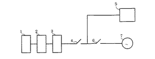
このような燃料電池発電システムとして、従来から提案されているものの一例を、図4及び図5に従って説明する。なお、本システムは、燃料電池本体の電気出力を商用の交流電力系統に接続して運転する系統連系運転を可能とするシステムである。すなわち、発電に必要な供給物を生成・調整する種々の供給物生成調整設備1が燃料電池本体2に接続されている。この燃料電池本体2の出力側は、逆変換装置3及びスイッチ4を経て単独負荷5に接続されている。また、燃料電池本体2の出力側は、逆変換装置3、スイッチ4、さらにスイッチ6を経て交流系統7に接続されている。
【0005】
以上のような燃料電池発電システムでは、燃料電池本体2は、供給物生成調整設備1から発電に必要な物質の供給を受け、直流電力を発生する。この直流電力は逆変換装置3によって交流電力に変換される。そして、通常運転時においては、スイッチ4及びスイッチ6を共に閉とすることで、単独負荷5に電力を供給しつつ、交流系統7との系統連系運転を行う。この状態で、交流系統側に異常が発生した時にはスイッチ6を開として、燃料電池本体2のみによる単独運転に移行する。また、燃料電池側が故障等で発電不能となった場合には、逆にスイッチ4を開として燃料電池本体2を切り離し、交流系統7によって単独負荷5に電力を供給する。以上のように、燃料電池側と交流系統側のいずれに故障が発生した場合であっても、故障箇所に応じてスイッチ6,7を切り替えることにより、単独負荷5に対して電力を連続的に供給することが可能となる。
【0006】
ところで、最近のコンピュータや医療用機器の分野では、その電源電圧や周波数において、商用系統よりもさらに安定した仕様が要求される機器が増大している。そして、このような機器に対応して、CVCF(定電圧定周波電源装置)やUPS(無停電電源装置)が開発され、広く使用されている。定電圧定周波電源装置とは、入力変動や出力負荷の変化に関係なく、出力の電圧及び周波数を一定に保つ装置である。無停電電源装置とは、交流入力が停電しても、ある一定期間、規定の交流電力を供給する装置である。ここで、一般的な燃料電池発電システムも、その構成上、逆変換装置を有しているため、交流系統とは切り離した単独運転を行うことによって、上記のような電力の安定供給用の電源として利用することができる。よって、近年、燃料電池の利用方法の一つとして関心が高まっている。
【0007】
但し、上記の図4に示した燃料電池発電システムを定電圧定周波電源装置や無停電電源装置として利用するには、以下のような問題がある。すなわち、スイッチ6を開状態として燃料電池本体2による単独運転を実施している場合において、燃料電池本体2に故障が発生した時、スイッチ6を閉とし、スイッチ4を開放するという手順を経る必要がある。しかし、かかる手順を経ていると、電力供給の瞬断が許されないコンピュータ等の無瞬断負荷において、通常要求される1/2サイクル以内の瞬時切替を満足することができない。
【0008】
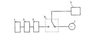
これに対処するため、現在では、図5に示すように、スイッチ4及びスイッチ6の代わりに、半導体による切替スイッチ8を用いたUPS代替システムが提案されている。このようなシステム構成においては、通常時は、切替スイッチ8は燃料電池側に接続され、燃料電池本体2による単独運転が実施されている。そして、燃料電池側の故障発生時等には、切替スイッチ8を1/2サイクル以下で交流系統7側に切り替え、交流系統7から単独負荷5に対して電力が供給される。さらに、燃料電池側の復旧後は、切替スイッチ8を元に戻し、燃料電池本体2から逆変換装置3を介して単独負荷5に対し電力を供給する。このように、瞬時の切替えが可能な半導体による切替スイッチ8を用いることによって、単独負荷5に対する電力供給の瞬断を防止することができる。
【0009】
【発明が解決しようとする課題】
しかしながら、上記のような燃料電池発電システムにおいては、故障状態にあった燃料電池本体2が復旧し、交流系統7から燃料電池本体2に切り替えて単独負荷5へ電力を供給する場合、燃料電池本体2や供給物生成調整設備1の負荷を、瞬時に0−100%に変化させることが必要となる。しかし、特別な装置無しに、このような早い負荷応答を実現させることは困難であり、発電に必要な反応物質や冷却水等が、供給物生成調製設備1から燃料電池本体2に供給されず、供給物生成調製設備1及び燃料電池本体2に無理なストレスがかかる。
【0010】
また、上記のような燃料電池発電システムの構成では、燃料電池本体2及び交流系統7のいずれか一方の側にしか切替スイッチ8の切替えを行うことができないため、燃料電池側と交流系統側とを連系させることができす、交流連系運転を実施する可能性がある場合には不向きであった。
【0011】
本発明は、以上のような従来技術の課題を解決するために提案されたものであり、その主たる目的は、燃料電池本体や供給物生成調製設備に無理なストレスがかかることなく、定電圧定周波電源や無停電電源装置として使用可能な燃料電池発電システムを提供することである。
【0012】
本発明の第2の目的は、燃料電池本体や供給物生成調製設備が最適な状態において、交流系統側からの電力供給を燃料電池側からの電力供給へ移行可能な燃料電池発電システムを提供することである。
【0013】
本発明の第3の目的は、定電圧定周波電源や無停電電源装置として使用可能であるとともに、交流系統連系運転も実現可能な燃料電池発電システムを提供することである。
【0014】
本発明の第4の目的は、燃料電池発電システムを定電圧定周波電源や無停電電源装置として使用しても、燃料電池本体や供給物生成調製設備に無理なストレスがかからない燃料電池発電システムの運転制御方法を提供することである。
【0015】
本発明の第5の目的は、交流系統側からの電力供給を燃料電池側からの電力供給へ移行する際に、燃料電池本体や供給物生成調製設備を最適な状態とすることが可能な燃料電池発電システムの運転制御方法を提供することである。
【0016】
【課題を解決するための手段】
上記の目的を達成するために、請求項1及び請求項2記載の発明は、直流電力を出力する燃料電池本体と、発電運転用の供給物質を生成調整して前記燃料電池本体に供給する供給物生成調整設備と、前記直流電力を交流電力に変換する逆変換装置と、前記逆変換装置からの電力及び交流系統からの電力を切り替えて負荷へ供給する切替手段とを有する燃料電池発電システムにおいて、以下のような技術的特徴を有する。
【0017】
すなわち、請求項1記載の発明は、前記切替手段によって前記負荷への電力供給を前記交流系統側から前記逆変換装置側へ切り替える前に、前記燃料電池本体の定格負荷電流値が設定され、前記定格負荷電流値に応じた信号を送出する設定電流信号生成手段と、前記設定電流信号生成手段からの信号に基づいて、前記供給物生成調整設備による前記燃料電池本体への前記供給物質の供給量を、前記定格負荷電流値に相当する量に調節する調節制御手段と、前記逆変換装置の出力側を前記交流系統側に直接接続する交流連系手段と、前記交流連系手段の切り離し及び接続を行う交流連系開閉手段とを有することを特徴とする。
【0018】
以上のような請求項1記載の発明では、負荷が交流系統からの電力の供給を受けている際に、負荷変化に対して律速過程となる供給物生成調整設備からの供給物質の供給量を、実際の負荷変化の前に定格負荷電流相当にまで上昇させておく。このため、交流系統側から逆変換装置側への切替えが行われる実際の負荷変化時には、発電に必要な物質の供給が不足することなく、瞬時負荷変化に対しても安定に運転を継続することができ、燃料電池本体及び供給物生成調整設備に無理なく負荷を投入することが可能となる。つまり、瞬時に燃料電池本体による単独運転に切り替えても、供給物生成調製設備及び燃料電池本体に無理なストレスがかからない。このため、運転の安定性が確保されるとともに装置寿命が延びる。
【0019】
また、交流連系開閉手段を備えた交流連系手段によって、燃料電池側と交流系統側とが直接接続されているので、交流連系開閉手段を開状態とすることによって単独運転が可能となり、閉状態とすることによって交流系統運転も可能となる。
【0020】
請求項2記載の発明は、前記負荷に対して実際に負荷されている交流電流及び交流電圧を測定する電流測定手段及び電圧測定手段と、前記電流測定手段及び前記電圧測定手段によって測定された実際の交流電流及び交流電圧に基づいて、消費電力及びその電力に相当する直流電流値を算出する演算手段と、前記切替手段によって前記負荷への電力供給を前記交流系統側から前記逆変換装置側へ切り替える前に、前記演算手段によって算出された直流電流値が入力され、前記直流電流値に関する信号を送出する設定電流信号生成手段と、前記設定電流信号生成手段からの信号に基づいて、前記供給物生成調整設備による前記燃料電池本体への前記供給物質の供給量を、前記演算手段によって算出された直流電流値に相当する量に調節する調節制御手段と、前記逆変換装置の出力側を前記交流系統側に直接接続する交流連系手段と、前記交流連系手段の切り離し及び接続を行う交流連系開閉手段とを有することを特徴とする。
【0021】
以上のような請求項2記載の発明では、負荷が交流系統からの電力の供給を受けている際に、負荷変化に対して律速過程となる供給物生成調整設備からの供給物質の供給量を、実際の負荷変化の前に、その時点での実際の負荷電力相当まで上昇させておく。このため、交流系統側から逆変換装置側への切替えが行われる実際の負荷変化時には、発電に必要な物質の供給が最適となり、瞬時負荷変化に対しても安定に運転を継続することができるので、燃料電池本体及び供給物生成調整設備が最適の状態で負荷を投入することが可能となる。
【0022】
そして、瞬時に燃料電池本体による単独運転に切り替えても、供給物生成調製設備及び燃料電池本体に無理なストレスがかからない。このため、請求項1の発明と同様に、運転の安定性確保、装置寿命の増大が図れるとともに、供給物質量の最適化によるコスト節約になる。
【0023】
さらに、交流連系開閉手段を備えた交流連系手段によって、燃料電池側と交流系統側とが直接接続されているので、交流連系開閉手段を開状態とすることによって単独運転が可 能となり、閉状態とすることによって交流系統運転も可能となる。
【0024】
また、請求項3記載の発明は、供給物質の供給を受けて直流電力を出力する燃料電池本体から、逆変換装置を介して負荷に電力を供給する状態と、交流系統から前記負荷に電力を供給する状態とを切り替えて電力供給を行う燃料電池発電システムの運転制御方法において、前記交流系統側による前記負荷への電力供給状態にあるときに、前記燃料電池本体への前記供給物質の供給量を増大させ、前記逆変換装置の出力側と前記交流系統側とを直接接続することによって、前記燃料電池の負荷を上昇させ、その後に、前記逆変換装置側による前記負荷への電力供給状態へ切り替えることを特徴とする。
【0025】
以上のような請求項3記載の発明では、負荷が交流系統からの電力の供給を受けている際に、負荷変化に対して律速過程となる供給物生成調整設備からの供給物質の供給量を、実際の負荷変化の前に上昇させておく。このため、交流系統側から逆変換装置側への切替えが行われる実際の負荷変化時には、発電に必要な物質の供給が不足することなく、瞬時負荷変化に対しても安定に運転を継続することができ、燃料電池本体及び供給物生成調整設備に無理なく負荷を投入することが可能となる。
【0026】
また、負荷が交流系統からの電力の供給を受けている際に、燃料電池側と交流系統側とを接続して交流連系モードにし、穏やかに燃料電池本体の負荷を上昇させる。そして、負荷が十分に高くなった後に、燃料電池本体による単独運転又は燃料電池本体と交流系統との交流連系運転に切り替える。すると、燃料電池本体及び供給物生成調整設備に無理なく負荷を投入することが可能となる。
【0027】
そして、瞬時の単独負荷接続においても供給物生成調整設備及び燃料電池本体に無理なストレスがかからず、運転の安定性が向上するとともに装置寿命が延びる。
【0028】
【発明の実施の形態】
以上のような本発明の実施の形態を、図面に従って以下に説明する。なお、図4及び図5に示した従来技術と同一の部材は、同一の符号を付し、説明は省略する。
【0029】
(1)第1の実施の形態
本発明の第1の実施の形態を、図1に従って以下に説明する。なお、請求項に記載の切替手段は切替スイッチ、設定電流信号生成手段は電流設定器、信号切替スイッチ及び設定関数とする。
【0030】
(構成)
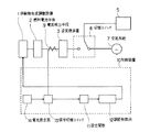
まず、本実施の形態の構成を説明する。すなわち、図1に示すように、燃料電池本体2と逆変換装置3との間に、直流電流を計測する電流検出手段9が設けられている。この電流検出手段9は制御装置10に接続されている。この制御装置10には、設定関数11、調節制御手段12、信号切替スイッチ13、電流設定器14が設定されている。
【0031】
このうち設定関数11は、直流電流信号の値に応じて、燃料電池発電反応に必要な供給物の供給量に関する信号を決定する関数である。そして、調節制御手段12は供給物生成調整設備1に接続され、設定関数11からの信号に従って、供給指令を供給物生成調整設備1に出力する制御系である。また、電流設定器14は、あらかじめ定められた定格負荷相当の直流電流信号が設定される設定器である。
【0032】
さらに、信号切替スイッチ13は、設定関数11に対して送出される信号を、電流検出手段9からの実際の直流電流信号と電流設定器14からの定格負荷相当の直流電流信号とのいずれかに切り替えるスイッチである。
【0033】
(作用)
以上のような構成を有する本実施の形態の作用は、以下の通りである。すなわち、通常時においては、切替スイッチ8は逆変換装置3側に接続されており、逆変換装置3からの電力による定電圧・定周波数の高品位電源運転が実施される。このとき、信号切替スイッチ13は電流検出手段9側に接続されているので、燃料電池本体2からの直流電流は電流検出手段9によって計測され、その計測値が制御装置10に取り込まれる。このように取り込まれた直流電流信号の値に応じて、制御装置10の設定関数11において、燃料流量、空気流量及び冷却水量等の燃料電池発電反応に必要な物質の供給量に関する信号が決定される。
【0034】
そして、設定関数11からの信号に応じて、調節制御手段12から供給物生成調整設備1に対して供給指令が出力されるので、各供給物質が決定された供給量に応じて燃料電池本体2に対し供給される。
【0035】
次に、燃料電池側の故障時には、切替スイッチ8が瞬時に交流系統7側に切り替わり、単独負荷5への無瞬断供給が実施される。そして、燃料電池本体2が復旧し、交流系統7からの電力に代わって再び燃料電池本体2からの電力に切り替える前に、あらかじめ信号切替スイッチ13を負荷設定器14側にしておく。すると、模擬的に定格負荷電流相当の信号が電流設定器14から設定関数11に与えられ、この定格負荷電流信号の値に応じて、制御装置10の設定関数11において、供給物質の供給量に関する信号が決定される。そして、設定関数11からの信号に応じて、調節制御手段12から供給物生成調整設備1に対して供給指令が出力されるので、供給物生成調製設備1から定格負荷電流相当の各供給物質が供給される。
【0036】
ここで、改質器等の化学反応器や配管、バルブ等によって構成される供給物生成調製設備1は、約5秒で定格負荷電流相当の供給物質の生成を行うことができるため、時間遅れ(タイムディレー)5秒の後、切替スイッチ8を逆変換装置3側とし、燃料電池本体2による単独運転状態とする。この後、信号切替スイッチ13を電流検出手段9側にし、実際の電流による通常制御状態に戻す。
【0037】
(効果)
以上のような本実施の形態の効果は以下の通りである。すなわち、燃料電池側が復旧し、再び負荷への供給電力を交流系統7の電力から燃料電池本体2の電力に切り替える際、事前に定格負荷電流相当の直流電流の増加を模擬的に実施することにより、発電に必要な供給物生成調整設備1での供給物質の生成供給量を確保させておくので、発電に十分な供給物質の供給能力を得ることができる。
【0038】
従って、タイムディレーの後、切替スイッチ8を逆変換装置3側とし、瞬時に燃料電池本体2による単独運転に切り替えても、供給物生成調製設備1及び燃料電池本体2に無理なストレスがかからない。このため、運転の安定性が確保されるとともに装置寿命が延びる。
【0039】
(2)第2の実施の形態
本発明の第2の実施の形態を、図2に従って以下に説明する。
【0040】
(構成)
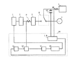
まず、本実施の形態の構成を説明する。すなわち、図2に示すように、本実施の形態は、第1の実施の形態において、単独負荷5へ供給される交流電圧、電流を計測する交流電圧検出手段15、交流電流検出手段16が設けられている。これら交流電圧検出手段15及び交流電流検出手段16は、制御装置10における演算手段19に接続されている。この演算手段19は、交流電圧検出手段15及び交流電流検出手段16の検出値から、消費電力及びその電力に相当する直流電流を演算手段19にて演算するものであり、電流設定器14に接続されている。
【0041】
(作用)
以上のような本実施の形態の作用は以下の通りである。すなわち、通常時は、上記第1の実施の形態と同様に、燃料電池本体2による単独運転が実施され、燃料電池側の故障時には、切替スイッチ8が瞬時に交流系統7側に切り替わり、単独負荷5への無瞬断供給が実施される。
【0042】
次に、燃料電池側が復旧し、交流系統7からの電力に代わって再び燃料電池本体2からの電力に切り替える前に、あらかじめ信号切替スイッチ13を電流設定器14側にしておく。そして、その時点で単独負荷5へ供給されている交流電圧、交流電流がそれぞれ交流電圧検出手段15、交流電流検出手段16によって計測され、演算手段19に送られる。演算手段19では、それら交流電圧、交流電流の検出値から消費電力及びその電力に相当する直流電流が演算され、その時点での実際の負荷電力相当の直流電流が電流設定器14に与えられる。
【0043】
信号切替スイッチ13は電流設定器14側となっているので、その時点での実際の負荷電力に相当する直流電流の信号が電流設定器14から設定関数11に与えられ、この定格負荷電流信号の値に応じて、制御装置10の設定関数11において、供給物質の供給量に関する信号が決定される。そして、設定関数11からの信号に応じて、調節制御手段12から供給物生成調整設備1に対して供給指令が出力されるので、供給物生成調製設備1から、実際の負荷電力に相当する各供給物質が供給される。
【0044】
ここで、供給物生成調製設備1は、約5秒で、その時点での実際の負荷電力に相当する供給物質の生成を行うことができるため、タイムディレー5秒の後、切替スイッチ8を逆変換装置3側とし、燃料電池本体2による単独運転状態とする。この後、信号切替スイッチ13を電流検出手段9側にし、実際の電流による通常制御状態に戻す。
【0045】
(効果)
以上のような本実施の形態の効果は以下の通りである。すなわち、燃料電池側が復旧し、再び負荷への供給電力を交流系統7の電力から燃料電池本体2の電力に切り替える際、事前にその時点での実際の単独負荷5への供給電力に相当する直流電流の増加を実施することにより、その時点での発電に最適な供給物生成調製設備1での供給物質の生成供給量を確保させておくので、発電に最も適した供給物質の供給能力を得ることができる。
【0046】
従って、タイムディレーの後、切替スイッチ8を逆変換装置3側とし、瞬時に燃料電池本体2による単独運転に切り替えても、供給物生成調整設備1及び燃料電池本体2に無理なストレスがかからない。このため、第1の実施の形態と同様に、運転の安定性確保、装置寿命の増大が図れるとともに、供給物質量の最適化によるコスト節約になる。
【0047】
(3)第3の実施の形態
本発明の第3の実施の形態を、図3に従って以下に説明する。なお、請求項に記載の交流連系手段はバイパスライン17とし、交流連系開閉手段はスイッチ18とする。
【0048】
(構成)
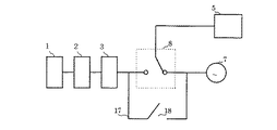
まず、本実施の形態の構成を説明する。すなわち、本実施の形態は、図3に示すように、図5で示した従来技術において、切替スイッチ8と並列に、逆変換装置2の出力側と交流系統7側とを電気的に連系するバイパスライン17が接続されている。そして、このバイパスライン17を開閉するスイッチ18が設けられている。
【0049】
(作用)
以上のような構成を有する本実施の形態の作用は、以下の通りである。すなわち、通常時においては、切替スイッチ8は逆変換装置3側に接続され、燃料電池本体2からの出力を交流系統7に連系するスイッチ18は開放とすることにより、逆変換装置3からの電力による定電圧・定周波の高品位電源運転が実施される。そして、燃料電池側の故障発生時等には、切替スイッチ8を瞬時に(例えば、1/2サイクル以下で)交流系統7側に切り替え、交流系統7から単独負荷5に対して電力を供給する。さらに、燃料電池側の復旧後は、切替スイッチ8を逆変換装置3側に戻し、燃料電池本体2から単独負荷5に電力を供給することにより、通常の定電圧・定周波数の高品位電源運転に移行させる。
【0050】
また、上記のような燃料電池側の故障発生前の通常運転状態又は復旧後の通常運転状態において、スイッチ18を閉とすることにより、必要に応じて適宜交流系統7との交流連系運転を実施する。
【0051】
(効果)
以上のような本実施の形態の効果は以下の通りである。すなわち、スイッチ18を開とすることにより、通常時は、逆変換装置3による定電圧・定周波数の高品位電源運転を実施でき、必要に応じてスイッチ18を閉とすることにより、交流系統7との交流連系運転が実施可能となる。
【0052】
(4)第4の実施の形態
本発明の第4の実施形態を、図3に従って以下に説明する。なお、本実施の形態は、図3に示した第3の実施の形態と同様の構成の燃料電池発電システムにおいて、以下のような運転制御を行うものである。
【0053】
すなわち、通常時においては、切替スイッチ8は燃料電池側に接続され、燃料電池本体2からの出力を交流系統7に連系するスイッチ18は開放とすることにより、逆変換装置3からの電力による定電圧・定周波の高品位電源運転が実施される。次に、燃料電池側の故障発生時等には、切替スイッチ8を瞬時に(例えば、1/2サイクル以下で)交流系統7側に切り替え、交流系統7から単独負荷5に対して電力を供給する。
【0054】
そして、燃料電池側の復旧後は、一度スイッチ18を閉として逆変換装置3の出力側と交流系統7とを直接接続し、燃料電池側を交流連系状態にして穏やかに負荷を増加させた後に、切替スイッチ8を逆変換装置3側に戻す。さらに、スイッチ18を開放して、燃料電池本体2から単独負荷5に電力を供給することにより、通常の定電圧・定周波数の高品位電源運転に移行させる。
【0055】
以上のような本実施の形態の効果は以下の通りである。すなわち、燃料電池側が復旧した後、燃料電池を交流連系状態にして穏やかに負荷を増加させた後に、燃料電池本体2に単独負荷5を接続するので、瞬時の単独負荷接続においても供給物生成調整設備1及び燃料電池本体2に無理なストレスがかからず、運転の安定性が向上するとともに装置寿命が延びる。また、第3の実施の形態と同様に、必要に応じてスイッチ18を閉とすることにより、交流系統7との交流連系運転が実施可能となる。
【0056】
(5)他の実施の形態
本発明は上記のような実施の形態に限定されるものではなく、各部材の種類、数、配置等は適宜変更可能である。例えば、燃料電池としては、現在最も開発が進んでいるりん酸型をはじめとして、溶融炭酸塩型、固体電解質型、アルカリ型、固体高分子型等、他の様々な種類のものが適用可能である。また、本発明は、定電圧定周波電源としても、無停電電源装置としても適用可能である。そして、制御装置は所定のプログラムによってコンピュータを作動させることによっても、専用の回路によっても実現可能である。
【0057】
さらに、上記第1の実施の形態又は第2の実施の形態に対して、第3の実施の形態と同様にバイパスライン17及びスイッチ18を設けることによって、請求項3及び請求項5記載の発明の他の実施の形態を実現することもできる。かかる実施の形態によれば、第1の実施の形態又は第2の実施の形態と同様の効果が得られるとともに、交流系統7との交流連系運転が可能となり、第3の実施の形態及び第4の実施の形態と同様の効果が得られる。
【0058】
【発明の効果】
以上説明したように、本発明によれば、燃料電池本体や供給物生成調製設備に無理なストレスがかかることなく、定電圧定周波電源や無停電電源装置として使用可能な燃料電池発電システムを提供することができる。
【0059】
本発明によれば、燃料電池本体や供給物生成調製設備が最適な状態において、交流系統側からの電力供給を燃料電池側からの電力供給へ移行可能な燃料電池発電システムを提供することができる。
【0060】
本発明によれば、定電圧定周波電源や無停電電源装置として使用可能であるとともに、交流系統連系運転も実現可能な燃料電池発電システムを提供することができる。
【0061】
本発明によれば、燃料電池発電システムを定電圧定周波電源や無停電電源装置として使用しても、燃料電池本体や供給物生成調製設備に無理なストレスがかからない燃料電池発電システムの運転制御方法を提供することができる。
【0062】
本発明によれば、交流系統側からの電力供給を燃料電池側からの電力供給へ移行する際に、燃料電池本体や供給物生成調製設備を最適な状態とすることが可能な燃料電池発電システムの運転制御方法を提供することができる。
【図面の簡単な説明】
【図1】本発明の燃料電池発電システムの第1の実施の形態を示す構成図である。
【図2】本発明の燃料電池発電システムの第2の実施の形態を示す構成図である。
【図3】本発明の燃料電池発電システムの第3の実施の形態を示す構成図である。
【図4】従来の燃料電池発電システムの一例を示す構成図である。
【図5】従来の燃料電池発電システムの一例を示す構成図である。
【符号の説明】
1…供給物生成調整装置
2…燃料電池本体
3…逆変換装置
4,6…スイッチ
5…単独負荷
7…交流系統
8…切替スイッチ
9…電流検出手段
10…制御装置
11…設定関数
12…調節制御手段
13…信号切替スイッチ
14…電流設定器
15…交流電圧検出手段
16…交流電流検出手段
17…バイパスライン
18…スイッチ
19…演算手段[0001]
BACKGROUND OF THE INVENTION
The present invention relates to a fuel cell power generation system used as, for example, a high-quality power source such as a constant voltage constant frequency power supply device or an uninterruptible power supply device, and in particular, for each component when switching from the AC system side to the fuel cell side. The present invention relates to a fuel cell power generation system with improved control and an operation control method thereof.
[0002]
[Prior art]
Generally, in a fuel cell power generation system, facilities for generating, adjusting and supplying an oxidant, a reducing agent and a coolant to a fuel cell main body are indispensable. The equipment for generating and adjusting the supply necessary for power generation includes an air blower and compressor as an oxidizer, a desulfurizer, a reformer and a carbon monoxide generator that generate hydrogen as a reducing agent, There are various types such as a heat exchanger for generating and circulating cooling water, a steam separator, a water treatment device, and pipes and valves for connecting them.
[0003]
The fuel cell power generation system includes an inverter (inverter) that converts the DC power of the fuel cell body into AC power, and a switch group that supplies AC power generated from the inverter to an AC system or a single load. It has. These switch groups are configured so that both AC system interconnection operation and isolated operation and smooth switching between each other can be performed.
[0004]
An example of such a fuel cell power generation system that has been conventionally proposed will be described with reference to FIGS. In addition, this system is a system which enables the grid connection operation | movement which connects and operates the electric output of a fuel cell main body to a commercial alternating current power system. That is, various supply
[0005]
In the fuel cell power generation system as described above, the fuel cell main body 2 receives supply of materials necessary for power generation from the supply
[0006]
By the way, in the field of recent computers and medical devices, there is an increasing number of devices that require more stable specifications than commercial systems in terms of power supply voltage and frequency. Corresponding to such devices, CVCF (constant voltage constant frequency power supply device) and UPS (uninterruptible power supply device) have been developed and widely used. A constant-voltage constant-frequency power supply device is a device that keeps the output voltage and frequency constant regardless of input fluctuations and output load changes. An uninterruptible power supply is a device that supplies a specified AC power for a certain period even when an AC input fails. Here, since a general fuel cell power generation system also has an inverse conversion device due to its configuration, a power supply for stable power supply as described above is performed by performing an independent operation separated from the AC system. Can be used as Therefore, in recent years, interest has increased as one of the methods of using fuel cells.
[0007]
However, there are the following problems in using the fuel cell power generation system shown in FIG. 4 as a constant voltage constant frequency power supply device or an uninterruptible power supply device. That is, in the case where the switch 6 is in an open state and the fuel cell main body 2 is operating alone, it is necessary to go through the procedure of closing the switch 6 and opening the switch 4 when a failure occurs in the fuel cell main body 2. There is. However, through such a procedure, instantaneous switching within a half cycle normally required cannot be satisfied in a non-instantaneous load such as a computer in which instantaneous interruption of power supply is not allowed.
[0008]
In order to cope with this, at present, as shown in FIG. 5, a UPS replacement system using a
[0009]
[Problems to be solved by the invention]
However, in the fuel cell power generation system as described above, when the fuel cell main body 2 in a faulty state is restored and the power is switched from the AC system 7 to the fuel cell main body 2 to supply power to the
[0010]
Further, in the configuration of the fuel cell power generation system as described above, since the
[0011]
The present invention has been proposed in order to solve the above-described problems of the prior art, and the main object of the present invention is to maintain a constant voltage without applying excessive stress to the fuel cell main body and the supply generation preparation facility. It is to provide a fuel cell power generation system that can be used as a frequency power supply or an uninterruptible power supply.
[0012]
The second object of the present invention is to provide a fuel cell power generation system capable of shifting the power supply from the AC system side to the power supply from the fuel cell side when the fuel cell main body and the feed generation preparation facility are in an optimal state. That is.
[0013]
A third object of the present invention is to provide a fuel cell power generation system that can be used as a constant voltage constant frequency power supply or an uninterruptible power supply and that can also realize an AC grid-connected operation.
[0014]
A fourth object of the present invention is to provide a fuel cell power generation system that does not place excessive stress on the fuel cell main body and the supply generation preparation equipment even when the fuel cell power generation system is used as a constant voltage constant frequency power supply or an uninterruptible power supply. It is to provide an operation control method.
[0015]
A fifth object of the present invention is a fuel capable of bringing the fuel cell main body and the supply generation preparation facility into an optimal state when the power supply from the AC system side is shifted to the power supply from the fuel cell side. It is providing the operation control method of a battery power generation system.
[0016]
[Means for Solving the Problems]
In order to achieve the above object,
[0017]
That is, according to the first aspect of the present invention, the rated load current value of the fuel cell main body is set before the power supply to the load is switched from the AC system side to the inverse conversion device side by the switching unit, Based on a signal from the set current signal generating means for sending a signal according to the rated load current value and the set current signal generating means, the supply amount of the supply substance to the fuel cell main body by the supply generation adjusting equipment Adjusting control means for adjusting the amount to a value corresponding to the rated load current value;And an AC interconnection means for directly connecting the output side of the inverse conversion device to the AC system side, and an AC interconnection opening / closing means for disconnecting and connecting the AC interconnection means.
[0018]
In the invention according to
[0019]
In addition, since the fuel cell side and the AC system side are directly connected by the AC interconnection means provided with the AC interconnection opening / closing means, it becomes possible to perform an independent operation by opening the AC interconnection opening / closing means, The AC system operation is also possible by setting the closed state.
[0020]
According to a second aspect of the present invention, there are provided current measuring means and voltage measuring means for measuring an alternating current and an alternating voltage actually loaded on the load, and actual measurements measured by the current measuring means and the voltage measuring means. Based on the AC current and the AC voltage, the calculation means for calculating the power consumption and the DC current value corresponding to the power, and the switching means supplies power to the load from the AC system side to the inverse converter side. Before switching, the DC current value calculated by the calculation means is input, and based on a signal from the set current signal generating means for sending a signal related to the DC current value, the supply An adjustment control for adjusting the supply amount of the supply substance to the fuel cell main body by the production adjustment facility to an amount corresponding to the direct current value calculated by the calculation means. And having means, the AC interconnection means for connecting directly the output side of the inverters to the ac system side, the AC interconnection switching means for performing disconnection and connection of the AC interconnection means.
[0021]
In the invention according to claim 2 as described above, when the load receives the supply of power from the AC system, the supply amount of the supply substance from the supply generation adjustment facility that becomes the rate-determining process with respect to the load change is reduced. Before the actual load change, the voltage is increased to the actual load power at that time. For this reason, at the time of an actual load change in which switching from the AC system side to the reverse conversion device side is performed, the supply of materials necessary for power generation is optimal, and the operation can be stably continued even with an instantaneous load change. Therefore, it is possible to load the fuel cell main body and the supply generation adjusting equipment in an optimal state.
[0022]
And even if it switches to the independent operation | movement with a fuel cell main body instantaneously, an unreasonable stress is not applied to a supply production preparation equipment and a fuel cell main body. For this reason, as in the first aspect of the invention, it is possible to ensure the stability of operation and increase the life of the apparatus, and to save costs by optimizing the amount of substance supplied.
[0023]
Further, since the fuel cell side and the AC system side are directly connected by the AC interconnection means provided with the AC interconnection opening / closing means, the independent operation is possible by opening the AC interconnection opening / closing means. AC system operation is also possible by setting the closed state.
[0024]
According to a third aspect of the present invention, there is provided a state in which power is supplied from a fuel cell body that receives supply of a supply substance and outputs DC power to a load via an inverter, and power is supplied from an AC system to the load. In the operation control method of the fuel cell power generation system for supplying power by switching the supply state, the supply amount of the supply substance to the fuel cell main body when the AC system is in the power supply state to the load And increasing the load of the fuel cell by directly connecting the output side of the inverter and the AC system side, and then the state of power supply to the load by the inverter It is characterized by switching.
[0025]
In the invention according to claim 3 as described above, when the load receives the supply of power from the AC system, the supply amount of the supply substance from the supply generation adjustment facility that becomes a rate-limiting process with respect to the load change is determined. Raise it before the actual load change. For this reason, at the time of actual load change when switching from the AC system side to the reverse conversion device side, supply of materials necessary for power generation is not insufficient, and stable operation is continued even against instantaneous load changes. Therefore, it is possible to load the fuel cell main body and the supply generation adjustment facility without difficulty.
[0026]
Further, when the load is supplied with power from the AC system, the fuel cell side and the AC system side are connected to enter the AC interconnection mode, and the load of the fuel cell body is gently increased. Then, after the load becomes sufficiently high, the operation is switched to the single operation by the fuel cell main body or the AC interconnection operation of the fuel cell main body and the AC system. Then, it becomes possible to load the fuel cell main body and the supply generation adjustment facility without difficulty.
[0027]
Even in the case of instantaneous single load connection, the supply generation adjusting equipment and the fuel cell main body are not subjected to excessive stress, so that the operational stability is improved and the life of the apparatus is extended.
[0028]
DETAILED DESCRIPTION OF THE INVENTION
Embodiments of the present invention as described above will be described below with reference to the drawings. The same members as those in the prior art shown in FIGS. 4 and 5 are denoted by the same reference numerals, and the description thereof is omitted.
[0029]
(1) First embodiment
The first embodiment of the present inventionThis will be described below with reference to FIG. In addition,ClaimedThe changeover means is a changeover switch, and the set current signal generation means is a current setter, a signal changeover switch, and a set function.
[0030]
(Constitution)
First, the configuration of the present embodiment will be described. That is, as shown in FIG. 1, current detection means 9 for measuring a direct current is provided between the fuel cell main body 2 and the inverse conversion device 3. The current detection means 9 is connected to the
[0031]
Among these, the setting function 11 is a function for determining a signal relating to the supply amount of the supply necessary for the fuel cell power generation reaction according to the value of the direct current signal. The adjustment control unit 12 is connected to the supply
[0032]
Further, the
[0033]
(Function)
The operation of the present embodiment having the above-described configuration is as follows. That is, in the normal time, the
[0034]
Then, in response to the signal from the setting function 11, the supply command is output from the adjustment control means 12 to the supply
[0035]
Next, in the event of a failure on the fuel cell side, the
[0036]
Here, the feed
[0037]
(effect)
The effects of the present embodiment as described above are as follows. That is, when the fuel cell side is restored and the power supplied to the load is switched again from the power of the AC system 7 to the power of the fuel cell main body 2, a DC current increase corresponding to the rated load current is simulated in advance. In addition, since the supply and generation amount of the supply substance in the supply
[0038]
Therefore, after the time delay, even if the
[0039]
(2) Second embodiment
The second embodiment of the present inventionThis will be described below with reference to FIG.
[0040]
(Constitution)
First, the configuration of the present embodiment will be described. That is, as shown in FIG. 2, the present embodiment is provided with the AC voltage detection means 15 and the AC current detection means 16 for measuring the AC voltage and current supplied to the
[0041]
(Function)
The operation of the present embodiment as described above is as follows. That is, in the normal state, as in the first embodiment, the single operation by the fuel cell main body 2 is performed, and when the fuel cell side fails, the
[0042]
Next, before the fuel cell side is restored and the power from the fuel cell main body 2 is switched again in place of the power from the AC system 7, the
[0043]
Since the
[0044]
Here, since the feed
[0045]
(effect)
The effects of the present embodiment as described above are as follows. That is, when the fuel cell side is restored and the power supplied to the load is switched again from the power of the AC system 7 to the power of the fuel cell main body 2, the direct current corresponding to the actual power supplied to the
[0046]
Therefore, after the time delay, even if the
[0047]
(3) Third embodiment
The third embodiment of the present inventionThis will be described below with reference to FIG. In addition,ClaimedThe AC interconnection means is a
[0048]
(Constitution)
First, the configuration of the present embodiment will be described. That is, in this embodiment, as shown in FIG. 3, in the prior art shown in FIG. 5, the output side of the inverter 2 and the AC system 7 side are electrically connected in parallel with the
[0049]
(Function)
The operation of the present embodiment having the above configuration is as follows. That is, in the normal time, the
[0050]
Moreover, in the normal operation state before the occurrence of a failure on the fuel cell side as described above or the normal operation state after recovery, the
[0051]
(effect)
The effects of the present embodiment as described above are as follows. That is, when the
[0052]
(4) Fourth embodiment
The fourth embodiment of the present inventionThis will be described below with reference to FIG. In the present embodiment, the following operation control is performed in the fuel cell power generation system having the same configuration as that of the third embodiment shown in FIG.
[0053]
That is, in the normal state, the
[0054]
Then, after the fuel cell side is restored, the
[0055]
The effects of the present embodiment as described above are as follows. That is, after the fuel cell side is restored, the fuel cell is made into an AC-linked state, and the load is gently increased, and then the
[0056]
(5) Other embodiments
The present invention is not limited to the embodiment as described above, and the type, number, arrangement, and the like of each member can be changed as appropriate. For example, various other types of fuel cells such as phosphoric acid type, which is currently under development, molten carbonate type, solid electrolyte type, alkaline type, solid polymer type, etc. can be applied. is there. In addition, the present invention can be applied as a constant voltage constant frequency power supply or an uninterruptible power supply. The control device can be realized by operating a computer according to a predetermined program or by a dedicated circuit.
[0057]
Furthermore, the invention according to claim 3 and
[0058]
【The invention's effect】
As explained above,The present inventionAccording to the present invention, it is possible to provide a fuel cell power generation system that can be used as a constant voltage constant frequency power supply or an uninterruptible power supply without applying excessive stress to the fuel cell main body or the supply generation preparation facility.
[0059]
The present inventionAccording to the present invention, it is possible to provide a fuel cell power generation system capable of shifting the power supply from the AC system side to the power supply from the fuel cell side in the optimal state of the fuel cell main body and the supply generation preparation facility.
[0060]
The present inventionAccording to the present invention, it is possible to provide a fuel cell power generation system that can be used as a constant voltage constant frequency power supply or an uninterruptible power supply and that can also realize an AC system interconnection operation.
[0061]
The present inventionProvides a method for controlling the operation of a fuel cell power generation system that does not place excessive stress on the fuel cell main body or supply generation preparation equipment even when the fuel cell power generation system is used as a constant voltage constant frequency power supply or an uninterruptible power supply. can do.
[0062]
The present inventionAccording to the above, when the power supply from the AC system side is shifted to the power supply from the fuel cell side, the operation of the fuel cell power generation system capable of bringing the fuel cell main body and the supply generation preparation equipment into an optimal state A control method can be provided.
[Brief description of the drawings]
FIG. 1 is a configuration diagram showing a first embodiment of a fuel cell power generation system of the present invention.
FIG. 2 is a configuration diagram showing a second embodiment of the fuel cell power generation system of the present invention.
FIG. 3 is a configuration diagram showing a third embodiment of the fuel cell power generation system of the present invention.
FIG. 4 is a configuration diagram showing an example of a conventional fuel cell power generation system.
FIG. 5 is a configuration diagram showing an example of a conventional fuel cell power generation system.
[Explanation of symbols]
1 ... Feed production control device
2. Fuel cell body
3 ... Inverse converter
4,6 ... switch
5 ... Single load
7 ... AC system
8 ... changeover switch
9. Current detection means
10 ... Control device
11 ... Setting function
12 ... Adjustment control means
13: Signal selector switch
14 ... Current setting device
15 ... AC voltage detection means
16: AC current detection means
17 ... Bypass line
18 ... Switch
19 ... Calculation means
Claims (3)
前記切替手段によって前記負荷への電力供給を前記交流系統側から前記逆変換装置側へ切り替える前に、前記燃料電池本体の定格負荷電流値が設定され、前記定格負荷電流値に応じた信号を送出する設定電流信号生成手段と、
前記設定電流信号生成手段からの信号に基づいて、前記供給物生成調整設備による前記燃料電池本体への前記供給物質の供給量を、前記定格負荷電流値に相当する量に調節する調節制御手段と、
前記逆変換装置の出力側を前記交流系統側に直接接続する交流連系手段と、
前記交流連系手段の切り離し及び接続を行う交流連系開閉手段とを有することを特徴とする燃料電池発電システム。A fuel cell main body that outputs DC power, a supply generation adjustment facility that generates and adjusts a supply substance for power generation operation and supplies the fuel cell main body, an inverse converter that converts the DC power into AC power, and In the fuel cell power generation system having switching means for switching the power from the reverse conversion device and the power from the AC system to supply to the load,
Before switching the power supply to the load from the AC system side to the inverse conversion device side by the switching means, the rated load current value of the fuel cell body is set, and a signal corresponding to the rated load current value is transmitted. Setting current signal generating means to perform,
Adjustment control means for adjusting the supply amount of the supply substance to the fuel cell main body by the supply generation adjustment facility based on a signal from the set current signal generation means to an amount corresponding to the rated load current value; ,
AC interconnection means for directly connecting the output side of the inverse converter to the AC system side;
The fuel cell power generation system further comprises AC interconnection switching means for disconnecting and connecting the AC interconnection means .
前記負荷に対して実際に負荷されている交流電流及び交流電圧を測定する電流測定手段及び電圧測定手段と、
前記電流測定手段及び前記電圧測定手段によって測定された実際の交流電流及び交流電圧に基づいて、消費電力及びその電力に相当する直流電流値を算出する演算手段と、
前記切替手段によって前記負荷への電力供給を前記交流系統側から前記逆変換装置側へ切り替える前に、前記演算手段によって算出された直流電流値が入力され、前記直流電流値に関する信号を送出する設定電流信号生成手段と、
前記設定電流信号生成手段からの信号に基づいて、前記供給物生成調整設備による前記燃料電池本体への前記供給物質の供給量を、前記演算手段によって算出された直流電流値に相当する量に調節する調節制御手段と、
前記逆変換装置の出力側を前記交流系統側に直接接続する交流連系手段と、
前記交流連系手段の切り離し及び接続を行う交流連系開閉手段とを有することを特徴とする燃料電池発電システム。A fuel cell main body that outputs DC power, a supply generation adjustment facility that generates and adjusts a supply substance for power generation operation and supplies the fuel cell main body, an inverse converter that converts the DC power into AC power, and In the fuel cell power generation system having switching means for switching the power from the reverse conversion device and the power from the AC system to supply to the load,
Current measuring means and voltage measuring means for measuring an alternating current and an alternating voltage actually loaded on the load;
Calculation means for calculating power consumption and a direct current value corresponding to the power based on the actual alternating current and the alternating voltage measured by the current measuring means and the voltage measuring means;
Before the switching means switches the power supply to the load from the AC system side to the inverse conversion device side, the setting is made so that the DC current value calculated by the calculation means is inputted and a signal relating to the DC current value is sent out. Current signal generating means;
Based on the signal from the set current signal generation means, the supply amount of the supply substance to the fuel cell main body by the supply generation adjustment equipment is adjusted to an amount corresponding to the direct current value calculated by the calculation means. Adjustment control means to
AC interconnection means for directly connecting the output side of the inverse converter to the AC system side;
A fuel cell power generation system comprising: AC interconnection switching means for disconnecting and connecting the AC interconnection means .
前記交流系統側による前記負荷への電力供給状態にあるときに、前記燃料電池本体への前記供給物質の供給量を増大させ、
前記逆変換装置の出力側と前記交流系統側とを直接接続することによって、前記燃料電池の負荷を上昇させ、
その後に、前記逆変換装置側による前記負荷への電力供給状態へ切り替えることを特徴とする燃料電池発電システムの運転制御方法。From the fuel cell body that receives the supply of the supply substance and outputs DC power, the power supply is switched between the state in which power is supplied to the load via the reverse conversion device and the state in which power is supplied from the AC system to the load. In the operation control method of the fuel cell power generation system to be performed,
When in the state of power supply to the load by the AC system side, increase the supply amount of the supply substance to the fuel cell body,
By directly connecting the output side of the inverse converter and the AC system side, the load of the fuel cell is increased,
After that, the operation control method for the fuel cell power generation system is switched to a power supply state to the load by the inverse converter side.
Priority Applications (1)
| Application Number | Priority Date | Filing Date | Title |
|---|---|---|---|
| JP34865796A JP3607025B2 (en) | 1996-12-26 | 1996-12-26 | Fuel cell power generation system and operation control method thereof |
Applications Claiming Priority (1)
| Application Number | Priority Date | Filing Date | Title |
|---|---|---|---|
| JP34865796A JP3607025B2 (en) | 1996-12-26 | 1996-12-26 | Fuel cell power generation system and operation control method thereof |
Publications (2)
| Publication Number | Publication Date |
|---|---|
| JPH10189020A JPH10189020A (en) | 1998-07-21 |
| JP3607025B2 true JP3607025B2 (en) | 2005-01-05 |
Family
ID=18398484
Family Applications (1)
| Application Number | Title | Priority Date | Filing Date |
|---|---|---|---|
| JP34865796A Expired - Fee Related JP3607025B2 (en) | 1996-12-26 | 1996-12-26 | Fuel cell power generation system and operation control method thereof |
Country Status (1)
| Country | Link |
|---|---|
| JP (1) | JP3607025B2 (en) |
Families Citing this family (5)
| Publication number | Priority date | Publication date | Assignee | Title |
|---|---|---|---|---|
| KR100748534B1 (en) | 2005-11-23 | 2007-08-13 | 엘지전자 주식회사 | Power supply and power supply method |
| JP4967380B2 (en) * | 2006-03-07 | 2012-07-04 | パナソニック株式会社 | Fuel cell power generation system |
| JP5376755B2 (en) * | 2006-12-26 | 2013-12-25 | 京セラ株式会社 | Fuel cell device and operation method thereof |
| JP6050757B2 (en) * | 2010-11-15 | 2016-12-21 | ブルーム エナジー コーポレーション | Fuel cell system capable of independent operation with DC microgrid function |
| JP6105460B2 (en) * | 2013-12-20 | 2017-03-29 | 京セラ株式会社 | Power control apparatus, power control system, and control method for power control system |
-
1996
- 1996-12-26 JP JP34865796A patent/JP3607025B2/en not_active Expired - Fee Related
Also Published As
| Publication number | Publication date |
|---|---|
| JPH10189020A (en) | 1998-07-21 |
Similar Documents
| Publication | Publication Date | Title |
|---|---|---|
| CN108093658B (en) | Systems and methods for fuel cell system ride-through for grid disturbances | |
| KR101967488B1 (en) | Method and arrangement to control operating conditions in fuel cell device | |
| WO2014002798A1 (en) | Solid polymer fuel cell system | |
| JP6894866B2 (en) | Power control system, power control device, and power control method | |
| JP2022136989A (en) | Microgrid including dual mode microgrid inverter and load management method | |
| JPWO2014002799A1 (en) | Solid oxide fuel cell system | |
| JP3607025B2 (en) | Fuel cell power generation system and operation control method thereof | |
| JPH04304126A (en) | Device for supplying electric power from fuel cell | |
| JP3502940B2 (en) | Operating method of fuel cell power generator and auxiliary power supply circuit | |
| JP5675675B2 (en) | Combined power generation system and method of operating combined power generation system | |
| JP2023071622A (en) | Power management in microgrids based on fuel cell systems | |
| JP3519899B2 (en) | Uninterruptible power system | |
| JP2001327100A (en) | Power system | |
| JPH09322555A (en) | System cooperation system | |
| JP2003174726A (en) | Operation management system of power supply apparatus | |
| JP2002171671A (en) | Instantaneous interruption independent transition power generation system | |
| JP6942565B2 (en) | Power generator, control device and control program | |
| JP2023169783A (en) | Power supply system, full load distribution board, power supply device, power supply control method for power supply device, power supply path, power conversion device, and connection method | |
| CN120999803A (en) | Control methods, devices, hydrogen production systems, media and process products for hydrogen production systems | |
| WO2023223434A1 (en) | Power feed system, full load distribution board, power feed device, power feed control method for power feed device, power feed path, power conversion device, and connection method | |
| JP4304829B2 (en) | Operation method of fuel cell power generator | |
| JP2002083619A (en) | Control method for fuel cell combined cycle system | |
| JPH0626131B2 (en) | Load control device for fuel cell system | |
| JP7754356B1 (en) | fuel cell system | |
| CN114498908A (en) | Uninterruptible power supply system and control method thereof |
Legal Events
| Date | Code | Title | Description |
|---|---|---|---|
| A131 | Notification of reasons for refusal |
Free format text: JAPANESE INTERMEDIATE CODE: A131 Effective date: 20040309 |
|
| A521 | Written amendment |
Free format text: JAPANESE INTERMEDIATE CODE: A523 Effective date: 20040510 |
|
| TRDD | Decision of grant or rejection written | ||
| A01 | Written decision to grant a patent or to grant a registration (utility model) |
Free format text: JAPANESE INTERMEDIATE CODE: A01 Effective date: 20040928 |
|
| A61 | First payment of annual fees (during grant procedure) |
Free format text: JAPANESE INTERMEDIATE CODE: A61 Effective date: 20041006 |
|
| FPAY | Renewal fee payment (event date is renewal date of database) |
Free format text: PAYMENT UNTIL: 20081015 Year of fee payment: 4 |
|
| FPAY | Renewal fee payment (event date is renewal date of database) |
Free format text: PAYMENT UNTIL: 20081015 Year of fee payment: 4 |
|
| FPAY | Renewal fee payment (event date is renewal date of database) |
Free format text: PAYMENT UNTIL: 20091015 Year of fee payment: 5 |
|
| LAPS | Cancellation because of no payment of annual fees |