JP3607020B2 - Washing machine - Google Patents
Washing machine Download PDFInfo
- Publication number
- JP3607020B2 JP3607020B2 JP30451096A JP30451096A JP3607020B2 JP 3607020 B2 JP3607020 B2 JP 3607020B2 JP 30451096 A JP30451096 A JP 30451096A JP 30451096 A JP30451096 A JP 30451096A JP 3607020 B2 JP3607020 B2 JP 3607020B2
- Authority
- JP
- Japan
- Prior art keywords
- outer tub
- cover
- dewatering
- tank
- groove
- Prior art date
- Legal status (The legal status is an assumption and is not a legal conclusion. Google has not performed a legal analysis and makes no representation as to the accuracy of the status listed.)
- Expired - Lifetime
Links
Images
Description
【0001】
【発明の属する技術分野】
本発明は外槽カバーの取付部分を改良した洗濯機に関する。
【0002】
【従来の技術】
従来より、いわゆる脱水兼用洗濯機においては、図4に示すように、上部に脱水口1を有する脱水槽2と、この脱水槽2を収容する外槽3とを具え、そして、その外槽3の上部の内周部に接してこれを覆う内覆い部4を有すると共に脱水槽2の上方部を覆う上覆い部5を有する環状の外槽カバー6を具えたものが供されている。
しかして、このものの場合、外槽カバー6は、図5に示すように、外槽3の外周部の数箇所に形成されたボス部7にそれぞれねじ8止めして取付けられている。
【0003】
【発明が解決しようとする課題】
上述のものの場合、脱水時に脱水槽2の回転による遠心力で脱水口1から振切り排出される水は、外槽カバー6によってそれ以上外方へ飛散するのが防止されるようになっている。しかしながら、外槽3の内周部のうち、ボス部7の裏側に位置する部分においては、ここにボス部7の厚みによる外槽3成形材(プラスチック)の冷却固化遅れが原因で凹み(いわゆる肉引け)9が図6に示すように生じ易く、万一凹み9が生じた場合には、この凹み9と外槽カバー6の内覆い部4との間を通して水が漏れ出ることになり、最終的にその水が洗濯機を据付けたところの床面に達してそれをぬらすという危惧を有していた。
【0004】
本発明は上述の事情に鑑みてなされたものであり、従ってその目的は、脱水時に脱水槽の脱水口から振切り排出される水に対しての遮断性能に優れ、床面のぬれ等を生じることのない洗濯機を提供するにある。
【0005】
上記目的を達成するために、本発明の洗濯機においては、上部に脱水口を有する脱水槽と、この脱水槽を収容する外槽とを具えると共に、その外槽の上部の内周部に実質的に接してこれを覆う内覆い部を有する環状の外槽カバーを具え、この外槽カバーを外槽の上部の外周部に形成したボス部にねじ止めして取付けるものにあって、そのボス部を外槽の上部の外周部から溝部で隔てて形成し、その溝部が外槽の上部の全周にあって、外槽カバーが内覆い部の外方に差込み部を有し、この差込み部を前記溝部に差込むと共に、その差込み部と前記内覆い部との間の溝部を外槽カバーの上部に嵌合したことを特徴とする。
【0006】
このものによれば、ボス部が外槽の上部の外周部から溝部で隔離されることにより、ボス部の厚みによる外槽成形材の固化遅れが原因の凹みは外槽の内周部にはできず、せいぜい溝部の外側面や内側面等にできるものであり、かくして、その凹みを通して水が漏れ出るということも避けられるようになる。
又、溝部が外槽の上部の全周にあって、外槽カバーが内覆い部の外方に差込み部を有し、この差込み部を前記溝部に差込むと共に、その差込み部と前記内覆い部との間の溝部を外槽カバーの上部に嵌合しているから、脱水槽の脱水口から振切り排出された水に対しての遮断性能を一段と良くでき、水の漏出をより確実に防止することができる。
【0007】
【発明の実施の形態】
以下、本発明の第1実施例につき、図1ないし図3を参照して説明する。
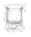
まず図2にはいわゆる脱水兼用洗濯機の全体構成を示しており、外箱11の内部に外槽12を弾性吊持機構13により揺動可能に支持して配設し、外槽12の内部に脱水槽14を回転可能に配設している。
【0008】
上記脱水槽14は下部から上部へ漸次径大となるテーパ状を成すようにプラスチックにより成形したもので、その上部にのみ脱水口15を横一列状配置の多数の孔で形成している。又、この脱水槽14の上部には内周部に例えば液体封入形のバランサ16を取付けており、これより下方の内周側部に通水孔17をほゞ全域に多数有する(一部のみ図示)円筒状の内バスケット18を取付け、底部に底カバー19を取付けると共に、撹拌体20を回転可能に配設している。
【0009】
外槽12の外下方部には駆動機構21を配設している。この駆動機構21は、洗濯時に脱水槽14を制止して撹拌体20を正逆両方向に回転させ、脱水時に脱水槽14を撹拌体20と共に一方向に回転させるもので、モータ22を駆動源として具えており、そのほか、ベルト伝動機構23、クラッチ機構24、及びブレーキ機構25等を具えている。
【0010】
又、外槽12の外下方部には排水弁26を配設している。この排水弁26は、洗濯時に脱水槽14内に溜めた水を排水時に内槽14の中心部から外槽12内底部の排水路27を通じて排水ホース28により機外に排出するものである。これに対して、脱水時及びオーバーフローすすぎ時には、脱水槽14の脱水口15から外槽12内に排出される水を、外槽12の底部に形成した排水口29から図示しない接続ホース(図示せず)を通じて同じく排水ホース28により機外に排出するようになっている。
【0011】
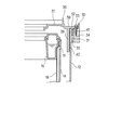
そして一方、外槽12の上部には、外周部に、図1に示す断面L字形の環状リブ30によって溝部31を形成している。この溝部31は外槽12の上部の外周部の全周に位置するもので、その外方側のリブ30内面の複数か所(例えば4か所)には、それぞれ半円柱状のボス部32を一体に形成している。しかして、このボス部32と外槽12の上部の外周部との間には溝部31の一部を余しており、これによって、ボス部32を外槽12の上部の外周部から溝部31で隔てて形成した形態としている。
【0012】
ボス部32にはねじ(この場合、タッピンねじ)33をねじ込むための下穴34を形成しており、又、溝部31の底部には、複数か所(例えばボス部32と合った4か所)に水抜き用の孔35を形成している。更に、溝部31の外側壁であるリブ30の外側部の高さは外槽12の周側部の高さより寸法Hだけ大きくしている。
【0013】
これに対して、外槽カバー36は、上覆い部37と取付部38とをほゞ水平状に有し、その境界部から内覆い部39を下方へほゞ垂直状に有する断面ほゞT字形の環状を成しており、その取付部38にねじ33より若干径大な取付孔40を上記下穴34と同数、同位置に形成している。又、内覆い部39の外方に位置してはこれより短寸の環状リブから成る差込み部41を取付部38から下方へ突出させて形成している。この差込み部41は溝部31に差込むためのもので、溝部31の中でも外槽12の上部の外周部とボス部32との間の部分に径方向の位置を合わせている。
【0014】
内覆い部39は長さLを取付状態で下端が脱水槽14の脱水口15より低く位置する寸法としており(図3参照)、この内覆い部39の外周面には例えばビニルテープから成るシール材42を装着している。
加えて、前記溝部31の底部に形成した水抜き用の孔35に対応し、その直下位置の外箱11底部には図2に示すように水受部43を形成している。
【0015】
この構成で、取付孔40が下穴34に合う位置から、内覆い部39を脱水槽14の内周部に沿って進め、差込み部41は溝部31に差込んで、取付部38を外槽12の上端面及びボス部32の上端面に載置する。そして、その後、図3に示すように、ねじ33を取付孔40に通し下穴34に螺挿して締付けることにより、外槽カバー36を外槽12の上部に取付け固定する。
【0016】
しかして、このように外槽12の上部に外槽カバー36を取付けた状態では、外槽12の上部の内周部を内覆い部39がシール材42によりそれに接して覆い、脱水槽14の上方部を上覆い部37が覆う。これにより、脱水時に脱水槽14の回転による遠心力で脱水口15から水が振切り排出されたとき、その水を外槽カバー36が上覆い部37と内覆い部39とで遮断し、それ以上外方へ飛散するのを防止する。
【0017】
この場合、特に外槽カバー36の取付けに供した外槽12のボス部32部分においては、ボス部32が外槽12の上部の外周部から溝部31で隔離されて形成されていることにより、ボス部32の厚みによる外槽12成形材(プラスチック)の固化遅れが原因の凹み(いわゆる肉引け)は外槽12の内周部にはできず、せいぜい溝部31の外側面(リブ30の外側面)や、溝部31の内側面にできる(ボス部32をリブ30の外側に設けた場合)ものであり、かくして、その凹みと外槽カバー36の内覆い部39との間を通して水が漏れ出る従来のような不具合の発生が避けられ、床面のぬれ等を生じないようにすることができる。
【0018】
又、特に上記構成のものでは、溝部31を外槽12の上部の外周部の全周に形成し、外槽カバー36には差込み部41を内覆い部39の外方の全周に形成していて、この差込み部41を溝部31に差込んでいるから、脱水槽14の脱水口15から振切り排出された水に対しての遮断性能を一段と良くでき、水の漏出をより確実に防止することができる。
【0019】
ことに、外槽12の上部の外周部と外槽カバー36の内覆い部39との接合部からの水漏れは、ボス部32部分の凹み(肉引け)以外に、外槽12の上部の外周部と外槽カバー36の内覆い部39との成形誤差による形状の不一致からも生じる可能性があるものであり、よって、このように溝部31に外槽カバー36の差込み部41を差込んで脱水槽14の脱水口15から振切り排出された水に対しての遮断性能を一段と良くすることは、水の漏出を防止する上で有効な手段といえる。
【0020】
更に、外槽カバー36の内覆い部39の外周面にはシール材42を装着しており、これが外槽12の内周面との間に介在されて、それらの間の密封をするから、これにても、脱水槽14の脱水口15から振切り排出された水に対しての遮断性能を一段と良くでき、水の漏出をより確実に防止することができる。
【0021】
加えて、外槽カバー36の内覆い部39は下端が脱水槽14の脱水口15より低く位置する長さとしており、これによっても脱水槽14の脱水口15から振切り排出された水に対しての遮断性能を一段と良くできるから、水の漏出をより確実に防止することができる。
【0022】
そして、溝部31が外槽12の上部の外周部の全周にあって、その底部に水抜き用の孔35を形成していることにより、万一、溝部31に水が溜まることがあっても、その水を孔35から抜いて排出でき、溝部31からの溢出することによる外槽12外への水の漏出を防止することができる。
【0023】
なお、この場合、更に孔35直下位置の外箱11底部には水受部43を形成しているから、孔35から抜いた水が床面に直接落ちることも防止できる。又、溝部31の外側壁であるリブ30の外側部の高さは外槽12の周側部の高さより大きくしているから、溝部31から外槽12外への水の漏出を一段と確実に防止することができる。
たゞし、これらの水受部43及びリブ30の外側部の高さは必ずしも必要な事柄ではなく、それらを必要とするもののみ施すようにすれば良い。
【0025】
なお、脱水槽14の脱水口15は脱水槽14の上部だけでなく、例えば周側部の全部など、上部以外の部分にも設けられていても良い。
このほか、本発明は上記し且つ図面に示した実施例にのみ限定されるものではなく、要旨を逸脱しない範囲内で適宜変更して実施し得る。
【0026】
【発明の効果】
本発明は以上説明したとおりのもので、下記の効果を奏する。
請求項1の洗濯機によれば、外槽に対する外槽カバーの取付けに供するボス部の厚みによる外槽成形材の固化遅れが原因の凹みが外槽の内周部にできず、その凹みを通して水が漏れ出るということが避けられるようになるから、脱水時に脱水槽の脱水口から振切り排出される水に対しての遮断性能に優れ、床面のぬれ等を生じることのないようにできる。
又、溝部が外槽の上部の全周にあって、外槽カバーが内覆い部の外方に差込み部を有し、この差込み部を前記溝部に差込むと共に、その差込み部と前記内覆い部との間の溝部を外槽カバーの上部に嵌合しているから、脱水槽の脱水口から振切り排出された水に対しての遮断性能を一段と良くでき、水の漏出をより確実に防止することができる。
【0027】
請求項2の洗濯機によれば、外槽カバーの内覆い部の外周面に装着したシール材が外槽の内周面との間に介在されて、それらの間の密封をするから、これにても、脱水槽の脱水口から振切り排出された水に対しての遮断性能を一段と良くでき、水の漏出をより確実に防止することができる。
【0028】
請求項3の洗濯機によれば、外槽カバーの内覆い部が下端が脱水槽の脱水口より低く位置する長さを有することで、脱水槽の脱水口から振切り排出された水に対しての遮断性能をやはり一段と良くでき、水の漏出をより確実に防止することができる。
請求項4の洗濯機によれば、万一、溝部に水が溜まることがあっても、その水を抜いて排出でき、溝部からの溢出することによる外槽外への水の漏出を防止することができる。
【図面の簡単な説明】
【図1】本発明の第1実施例を示す主要部分の分解斜視図
【図2】全体の破断側面図
【図3】主要部分の縦断側面図
【図4】従来例を示す図2相当図
【図5】主要部分の破断斜視図
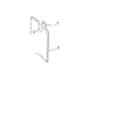
【図6】図6部分相当拡大図
【符号の説明】
12は外槽、14は脱水槽、15は脱水口、30はリブ、31は溝部、32はボス部、33はねじ、35は孔、36は外槽カバー、39は内覆い部、41は差込み部、42はシール材、Lは内覆い部の長さ、51は溝部、52はボス部を示す。[0001]
BACKGROUND OF THE INVENTION
The present invention relates to a washing machine having an improved mounting portion of an outer tub cover.
[0002]
[Prior art]
Conventionally, in a so-called dewatering combined washing machine, as shown in FIG. 4, it comprises a
Thus, in this one, the outer tub cover 6, as shown in FIG. 5, is attached by
[0003]
[Problems to be solved by the invention]
In the case of the above, the water discharged from the dewatering port 1 by centrifugal force due to the rotation of the dewatering
[0004]
The present invention has been made in view of the above-described circumstances, and therefore the object thereof is excellent in blocking performance against water that is shaken and discharged from the dewatering port of the dewatering tank at the time of dewatering, and causes floor wetting and the like. To provide a washing machine that never happens.
[0005]
In order to achieve the above object, the washing machine of the present invention comprises a dewatering tub having a dewatering port in the upper portion and an outer tub that accommodates the dewatering tub, and an inner peripheral portion at the upper portion of the outer tub. An annular outer tub cover having an inner covering portion that substantially contacts and covers the outer tub cover is provided, and the outer tub cover is attached by screwing to a boss formed on the outer peripheral portion of the upper portion of the outer tub. The boss part is formed with a groove part separated from the outer peripheral part of the upper part of the outer tub , the groove part is on the entire periphery of the upper part of the outer tub, and the outer tub cover has an insertion part on the outer side of the inner covering part. The insertion portion is inserted into the groove portion, and the groove portion between the insertion portion and the inner cover portion is fitted to the upper portion of the outer tank cover .
[0006]
According to this, the boss part is separated from the outer peripheral part of the upper part of the outer tub by the groove part, so that the recess caused by the solidification delay of the outer tub molding material due to the thickness of the boss part is in the inner peripheral part of the outer tub. This is not possible, and at most it can be formed on the outer side surface or inner side surface of the groove portion, and thus it is possible to avoid the leakage of water through the recess.
Further, the groove portion is on the entire circumference of the upper portion of the outer tub, and the outer tub cover has an insertion portion on the outer side of the inner covering portion. The insertion portion is inserted into the groove portion, and the insertion portion and the inner covering are provided. Since the groove between this part is fitted to the upper part of the outer tank cover, it can further improve the blocking performance against the water that is shaken and discharged from the dewatering port of the dewatering tank, and more reliably leak water. Can be prevented.
[0007]
DETAILED DESCRIPTION OF THE INVENTION
A first embodiment of the present invention will be described below with reference to FIGS.
First, FIG. 2 shows an overall configuration of a so-called dehydrating washing machine, in which an
[0008]
The
[0009]
A
[0010]
In addition, a drain valve 26 is disposed on the outer lower portion of the
[0011]
On the other hand, a
[0012]
The
[0013]
On the other hand, the
[0014]
The
In addition, a
[0015]
With this configuration, the
[0016]
Thus, in the state where the
[0017]
In this case, in particular, in the
[0018]
In particular, in the above configuration, the
[0019]
In particular, water leakage from the joint between the outer peripheral portion of the upper portion of the
[0020]
Furthermore, a sealing
[0021]
In addition, the
[0022]
And since the
[0023]
In this case, since the
However, the heights of the
[0025]
Note that the
In addition, the present invention is not limited to the embodiments described above and shown in the drawings, and can be implemented with appropriate modifications without departing from the scope of the invention.
[0026]
【The invention's effect】
The present invention is as described above and has the following effects.
According to the washing machine of claim 1, the recess caused by the solidification delay of the outer tub molding material due to the thickness of the boss portion provided for the attachment of the outer tub cover to the outer tub cannot be formed in the inner peripheral portion of the outer tub, and through the recess Since it is avoided that water leaks out, it has excellent blocking performance against water that is shaken and discharged from the dewatering port of the dewatering tank during dehydration, and can prevent floor wetting etc. .
Further, the groove portion is on the entire circumference of the upper portion of the outer tub, and the outer tub cover has an insertion portion on the outer side of the inner covering portion. The insertion portion is inserted into the groove portion, and the insertion portion and the inner covering are provided. Since the groove between this part is fitted to the upper part of the outer tank cover, it can further improve the blocking performance against the water that is shaken and discharged from the dewatering port of the dewatering tank, and more reliably leak water. Can be prevented.
[0027]
According to the washing machine according to
[0028]
According to the washing machine of claim 3 , the inner cover part of the outer tub cover has a length such that the lower end is positioned lower than the dewatering port of the dewatering tub, so that the water discharged from the dewatering port of the dewatering tub is shaken and discharged. All the blocking performance can be further improved, and water leakage can be prevented more reliably.
According to the washing machine of
[Brief description of the drawings]
It exploded perspective view FIG. 2 overall cutaway side view [FIG 3 is a longitudinal side view Figure 2 corresponding to FIG. 4 shows a conventional example of the main part of the main part showing a first embodiment of the present invention; FIG FIG. 5 is a cutaway perspective view of the main part . FIG . 6 is an enlarged view corresponding to the part of FIG .
12 is an outer tub, 14 is a dewatering tub, 15 is a dewatering port, 30 is a rib, 31 is a groove, 32 is a boss, 33 is a screw, 35 is a hole, 36 is an outer tub cover, 39 is an inner cover, 41 is The insertion portion, 42 is a sealing material, L is the length of the inner covering portion, 51 is a groove portion, and 52 is a boss portion.
Claims (4)
Priority Applications (1)
| Application Number | Priority Date | Filing Date | Title |
|---|---|---|---|
| JP30451096A JP3607020B2 (en) | 1996-11-15 | 1996-11-15 | Washing machine |
Applications Claiming Priority (1)
| Application Number | Priority Date | Filing Date | Title |
|---|---|---|---|
| JP30451096A JP3607020B2 (en) | 1996-11-15 | 1996-11-15 | Washing machine |
Publications (2)
| Publication Number | Publication Date |
|---|---|
| JPH10137487A JPH10137487A (en) | 1998-05-26 |
| JP3607020B2 true JP3607020B2 (en) | 2005-01-05 |
Family
ID=17933913
Family Applications (1)
| Application Number | Title | Priority Date | Filing Date |
|---|---|---|---|
| JP30451096A Expired - Lifetime JP3607020B2 (en) | 1996-11-15 | 1996-11-15 | Washing machine |
Country Status (1)
| Country | Link |
|---|---|
| JP (1) | JP3607020B2 (en) |
Families Citing this family (7)
| Publication number | Priority date | Publication date | Assignee | Title |
|---|---|---|---|---|
| KR100548712B1 (en) * | 1998-04-21 | 2006-05-17 | 주식회사 엘지이아이 | Leakage prevention structure of washing machine with rotating cylinder |
| AU761962B2 (en) * | 1998-08-18 | 2003-06-12 | Lg Electronics Inc. | Penetration type washing machine, method for controlling the same, and tub cover for the same |
| KR100307233B1 (en) * | 1999-05-15 | 2001-09-26 | 구자홍 | Washing machine |
| KR100370012B1 (en) * | 2000-04-20 | 2003-02-05 | 엘지전자 주식회사 | sealing device for a automatic washer |
| KR100362858B1 (en) * | 2000-06-29 | 2002-12-11 | 엘지전자 주식회사 | tube cover of washing machine |
| KR20030064567A (en) * | 2002-01-28 | 2003-08-02 | 주식회사 엘지이아이 | Water discharge structure of tub cover for washing machine |
| JP4020820B2 (en) * | 2003-04-15 | 2007-12-12 | 松下電器産業株式会社 | Washing and drying machine |
-
1996
- 1996-11-15 JP JP30451096A patent/JP3607020B2/en not_active Expired - Lifetime
Also Published As
| Publication number | Publication date |
|---|---|
| JPH10137487A (en) | 1998-05-26 |
Similar Documents
| Publication | Publication Date | Title |
|---|---|---|
| KR0182732B1 (en) | Balancer of a washing machine | |
| JP3607020B2 (en) | Washing machine | |
| WO2019205911A1 (en) | Washing machine | |
| JP2021515637A (en) | Washing machine | |
| JPH09220395A (en) | Rotating vessel of dewatering-and-washing machine | |
| TWI844693B (en) | Drum washing machine | |
| JP3340828B2 (en) | Dehydration combined washing machine | |
| JPH08150286A (en) | Dehydrating washing machine | |
| JPS5833988Y2 (en) | Lint removal device for dehydrating washing machine | |
| JPS6238627Y2 (en) | ||
| JP3839499B2 (en) | One tank washing machine | |
| JPS6041919Y2 (en) | Dehydration/washing machine | |
| KR970002141Y1 (en) | A drain guide construction of an automation washing machine | |
| JPS6018230Y2 (en) | Dehydration/washing machine | |
| JPH07213784A (en) | Spin-drying/washing machine | |
| KR940006376Y1 (en) | Laundry escape protection structure of washing machine | |
| JPH0223257Y2 (en) | ||
| JPH08191987A (en) | Dehydrating/washing machine | |
| KR200142660Y1 (en) | The drain hose connector for a washing machine | |
| JP3760453B2 (en) | Two tank washing machine | |
| JP2678972B2 (en) | Drain trap for dewatering sinks | |
| KR100255856B1 (en) | Washing machine of dry tub | |
| KR200174325Y1 (en) | Bellows in a washing machine | |
| KR900001298Y1 (en) | Bellows for washing machine | |
| KR200187381Y1 (en) | Leak of water check structure of a washing machine |
Legal Events
| Date | Code | Title | Description |
|---|---|---|---|
| A02 | Decision of refusal |
Free format text: JAPANESE INTERMEDIATE CODE: A02 Effective date: 20040330 |
|
| A521 | Written amendment |
Free format text: JAPANESE INTERMEDIATE CODE: A523 Effective date: 20040514 |
|
| A911 | Transfer of reconsideration by examiner before appeal (zenchi) |
Free format text: JAPANESE INTERMEDIATE CODE: A911 Effective date: 20040610 |
|
| TRDD | Decision of grant or rejection written | ||
| A01 | Written decision to grant a patent or to grant a registration (utility model) |
Free format text: JAPANESE INTERMEDIATE CODE: A01 Effective date: 20040928 |
|
| A61 | First payment of annual fees (during grant procedure) |
Free format text: JAPANESE INTERMEDIATE CODE: A61 Effective date: 20041006 |
|
| FPAY | Renewal fee payment (event date is renewal date of database) |
Free format text: PAYMENT UNTIL: 20081015 Year of fee payment: 4 |
|
| FPAY | Renewal fee payment (event date is renewal date of database) |
Free format text: PAYMENT UNTIL: 20081015 Year of fee payment: 4 |
|
| FPAY | Renewal fee payment (event date is renewal date of database) |
Free format text: PAYMENT UNTIL: 20091015 Year of fee payment: 5 |
|
| FPAY | Renewal fee payment (event date is renewal date of database) |
Free format text: PAYMENT UNTIL: 20091015 Year of fee payment: 5 |
|
| FPAY | Renewal fee payment (event date is renewal date of database) |
Free format text: PAYMENT UNTIL: 20101015 Year of fee payment: 6 |
|
| FPAY | Renewal fee payment (event date is renewal date of database) |
Free format text: PAYMENT UNTIL: 20111015 Year of fee payment: 7 |
|
| FPAY | Renewal fee payment (event date is renewal date of database) |
Free format text: PAYMENT UNTIL: 20111015 Year of fee payment: 7 |
|
| FPAY | Renewal fee payment (event date is renewal date of database) |
Free format text: PAYMENT UNTIL: 20121015 Year of fee payment: 8 |
|
| FPAY | Renewal fee payment (event date is renewal date of database) |
Free format text: PAYMENT UNTIL: 20121015 Year of fee payment: 8 |
|
| FPAY | Renewal fee payment (event date is renewal date of database) |
Free format text: PAYMENT UNTIL: 20131015 Year of fee payment: 9 |
|
| R157 | Certificate of patent or utility model (correction) |
Free format text: JAPANESE INTERMEDIATE CODE: R157 |
|
| S111 | Request for change of ownership or part of ownership |
Free format text: JAPANESE INTERMEDIATE CODE: R313117 Free format text: JAPANESE INTERMEDIATE CODE: R313114 Free format text: JAPANESE INTERMEDIATE CODE: R313111 |
|
| R350 | Written notification of registration of transfer |
Free format text: JAPANESE INTERMEDIATE CODE: R350 |
|
| EXPY | Cancellation because of completion of term |


