JP3606892B2 - Reactive liquid vaporizer and vapor deposition system for chemical vapor deposition process. - Google Patents
Reactive liquid vaporizer and vapor deposition system for chemical vapor deposition process. Download PDFInfo
- Publication number
- JP3606892B2 JP3606892B2 JP31546693A JP31546693A JP3606892B2 JP 3606892 B2 JP3606892 B2 JP 3606892B2 JP 31546693 A JP31546693 A JP 31546693A JP 31546693 A JP31546693 A JP 31546693A JP 3606892 B2 JP3606892 B2 JP 3606892B2
- Authority
- JP
- Japan
- Prior art keywords
- valve
- liquid
- hole
- vaporizer
- input port
- Prior art date
- Legal status (The legal status is an assumption and is not a legal conclusion. Google has not performed a legal analysis and makes no representation as to the accuracy of the status listed.)
- Expired - Lifetime
Links
Images


Classifications
-
- C—CHEMISTRY; METALLURGY
- C23—COATING METALLIC MATERIAL; COATING MATERIAL WITH METALLIC MATERIAL; CHEMICAL SURFACE TREATMENT; DIFFUSION TREATMENT OF METALLIC MATERIAL; COATING BY VACUUM EVAPORATION, BY SPUTTERING, BY ION IMPLANTATION OR BY CHEMICAL VAPOUR DEPOSITION, IN GENERAL; INHIBITING CORROSION OF METALLIC MATERIAL OR INCRUSTATION IN GENERAL
- C23C—COATING METALLIC MATERIAL; COATING MATERIAL WITH METALLIC MATERIAL; SURFACE TREATMENT OF METALLIC MATERIAL BY DIFFUSION INTO THE SURFACE, BY CHEMICAL CONVERSION OR SUBSTITUTION; COATING BY VACUUM EVAPORATION, BY SPUTTERING, BY ION IMPLANTATION OR BY CHEMICAL VAPOUR DEPOSITION, IN GENERAL
- C23C16/00—Chemical coating by decomposition of gaseous compounds, without leaving reaction products of surface material in the coating, i.e. chemical vapour deposition [CVD] processes
- C23C16/44—Chemical coating by decomposition of gaseous compounds, without leaving reaction products of surface material in the coating, i.e. chemical vapour deposition [CVD] processes characterised by the method of coating
- C23C16/448—Chemical coating by decomposition of gaseous compounds, without leaving reaction products of surface material in the coating, i.e. chemical vapour deposition [CVD] processes characterised by the method of coating characterised by the method used for generating reactive gas streams, e.g. by evaporation or sublimation of precursor materials
- C23C16/4481—Chemical coating by decomposition of gaseous compounds, without leaving reaction products of surface material in the coating, i.e. chemical vapour deposition [CVD] processes characterised by the method of coating characterised by the method used for generating reactive gas streams, e.g. by evaporation or sublimation of precursor materials by evaporation using carrier gas in contact with the source material
-
- B—PERFORMING OPERATIONS; TRANSPORTING
- B01—PHYSICAL OR CHEMICAL PROCESSES OR APPARATUS IN GENERAL
- B01F—MIXING, e.g. DISSOLVING, EMULSIFYING OR DISPERSING
- B01F23/00—Mixing according to the phases to be mixed, e.g. dispersing or emulsifying
- B01F23/10—Mixing gases with gases
- B01F23/12—Mixing gases with gases with vaporisation of a liquid
-
- Y—GENERAL TAGGING OF NEW TECHNOLOGICAL DEVELOPMENTS; GENERAL TAGGING OF CROSS-SECTIONAL TECHNOLOGIES SPANNING OVER SEVERAL SECTIONS OF THE IPC; TECHNICAL SUBJECTS COVERED BY FORMER USPC CROSS-REFERENCE ART COLLECTIONS [XRACs] AND DIGESTS
- Y10—TECHNICAL SUBJECTS COVERED BY FORMER USPC
- Y10S—TECHNICAL SUBJECTS COVERED BY FORMER USPC CROSS-REFERENCE ART COLLECTIONS [XRACs] AND DIGESTS
- Y10S261/00—Gas and liquid contact apparatus
- Y10S261/65—Vaporizers
Description
【0001】
【産業上の利用分野】
本発明は、主に、制御された割合で液体を気化させるための装置に関する。より詳細には、液体及びキャリアガスの流量を独自に制御する方法で、急速な圧力低下状態で液体を気化させ、この気化された液体とキャリアガスとを混合する装置に関する。本発明は、特に、気化された反応物を化学的蒸着システムの反応室に供給するには好適である。
【0002】
【従来の技術】
化学的蒸着(Chemical vapor deposition : CVD )プロセスは、半導体デバイスや集積回路に使用される薄膜の形成に広く用いられる。このようなプロセスは、基板上の同種の物質、或いは異種の物質からなる化学的蒸気の反応の結果として生じる蒸着を伴う。この反応速度は、たとえば、温度、圧力或いは反応ガスの流量等によって制御される。このようなプロセスのための前駆物質(precursors)として、低蒸気圧の液体を使用することは、いくつかの利点を有しており、この方法がより一般的になりつつある。
【0003】
【発明が解決しようとする課題】
CVDプロセスの前には、バブラー或いはボイラーを用いて低蒸気圧液体の輸送を行う。このプロセスにおいて、キャリアガスは、その液体を十分に含有してその蒸気を輸送する。輸送される蒸気量は、下流の圧力、キャリアガスの流量、原料液源(source liquid source)を収容したアンプル内の蒸気圧等に依存する。このように、輸送される蒸気量は独立したパラメータではないためその制御は困難である。その結果、バブラーやボイラーを用いるCVDプロセスは、気化された反応物の流量を一貫して制御する能力を明示しておらず、このことは、これらのプロセスによって生産された膜の質を低下させる。
【0004】
バブラーを用いたCVDプロセスの付加的な欠点は、これらのプロセスが高い薄膜蒸着速度を達成するために必要な、多大な反応物流量を作り出すことが困難であるということである。バブラーでは、反応物流量を増加するには、バブラー温度を上昇させるか、或いはキャリアガス流量を増大させることが要求される。しかしながら、下流のハードウエアの信頼性は、定められた量を上回る温度の使用を制限し、また、蒸着膜の質における、過度のキャリアガス流量の悪影響は、多大なキャリアガス流量の使用を制限し、これは輸送されるべき蒸気量を制限する。このように、輸送されるべき反応物蒸気の量は、希望に反する制限を受けることになる。
【0005】
既知のボイラーでは、液体が加熱されて形成される蒸気は、高温ガス流量コントローラを用いて制御される。この装置構成において、輸送される蒸気量は、下流のチャンバー圧力とボイラー温度に依存する。しかしながら、半導体膜(たとえば、tetraethylorthosilane TEOS)の蒸着に用いられる一般的な液体の蒸気圧は、通常の運転温度において非常に低い。この結果、ボイラーが高圧(たとえば、大気圧)CVDプロセスで使用される際に、蒸気輸送の制限が生じる。ボイラーを液体の沸騰温度に加熱することは、このようなプロセスのための蒸気輸送を明らかに改善することができるが、ボイラー温度は下流のハードウエアの信頼性にによって制限されてしまう。
【0006】
先に提出された米国特許出願(出願番号07/912024)には、CVDプロセスについて記載されており、このプロセスは、液体のビード(a bead of liquid) を越えて加熱されたキャリアガスを流すことによって蒸気が形成される。液体がキャリアガス内で気化し、CVDのための反応物蒸気を作り出す。気化速度は、ビード中の液体の流量を調整することによって制御される。すなわち、大流量では、気化速度が液体の流量に等しくなるまで、ビードのサイズと表面領域が増加する。しかしながら、上述の与えられた制限において、液体流量の増加は、単なる部分的な気化となるであろう。バブラー及びボイラー技術を越える、このプロセスの利点は、液体流量を独自に制御するということである。しかし、バブラー及びボイラー技術と同じように、この技術は液体を気化させるために加熱蒸気に依存し、このため、結局、制限された気化速度を作り出す傾向がある。
【0007】
その結果、大流量で液体を気化させることができ、加えて、液体とキャリアガスの流量を独自に制御する、信頼できかつ軽保守の液体気化器が、依然として望まれている。本発明はこの要求に向けられる。
【0008】
【課題を解決するための手段】
本発明は、キャリアガスと加圧液体とを受け入れる気化器を特徴とする。内部空孔(internal cavity)はキャリア孔(carrier aperture)を介してキャリアガスを受け入れ、液体孔(liquid aperture) を介して受け入れられる液体から形成される蒸気をこのキャリアガスと混合する。混合されたガスと蒸気は、第3の孔を経由してこの空孔から排出される。この液体は、液体と気体との間の圧力差によって気化される。液体孔とこの空孔の残材(remainder)との間に圧力勾配を形成するため、この液体孔よりも実質的に大きな遮断要素はこの液体孔に隣接して配置される。この圧力勾配を通過する液体は、膨脹のために気化される。
【0009】
この発明の有利な点は、加熱による蒸発というよりもむしろ圧力勾配下の膨脹により蒸気を形成し、このため、多くの半導体製作プロセスで必要とされるような高流量で液体を気化することができるということである。
【0010】
好ましい実施例として、遮断要素は液体の流路を増減させるために液体孔に隣接した移動可能なダイアフラムである。この遮断要素は、圧電素子のように、電気的に制御されるアクチュエータによって移動される。液体の流量を制御するために液体流量メーターが接続され、液体入力ポート内の液体の流量を計測する。フィードバック制御システムは、計測された流量と選択値とを比較し、その流量が選択値に近付くように、圧電アクチュエータを制御する。
【0011】
この発明の有利な点は、液体の流量はダイアフラムの動きによって単独に制御され、このため(上述した従来の気化システムとは全く相違するように)、液体の流量はキャリアガスの流量と独立であり、それゆえ、より正確に制御することが可能である。
【0012】
さらに好ましい実施例において、液体が気化した後、膨脹のために冷却された液体が、空孔内の壁上に液化するのを防止するため、少なくとも空孔近傍のバルブ本体を加熱装置で加熱する。
【0013】
【実施例】
さて図面を参照すると、より詳細には図1であり、ここには一段において液体流量制御と気化の双方のために特に設計された気化器12を用いた液体分配(delivery) システムが示される。液体流量は、液体流量モニター14と気化器12との間の閉ループシステムによって制御される。このシステム10では、TEOSのような液体反応物(liquid reactant)11、ホウ酸トリメチル、ホウ酸テトラエチル、リン酸テトラエチル、亜リン酸テトラエチル、テトラキス(ジメチルアミノ)チタニウムジエチルアナローグ、水等は、液体バルク分配タンク16から、通常の熱タイプか或いはプラズマ励起タイプのCVDプロセスチャンバー18に分配される。例えば、このようなチャンバー18は、以下に示す米国特許の中に一般的に開示されている。すなわち、1991年3月19にAdamik等に与えられた米国特許5000113号、1987年5月26日にFoster等に与えられた米国特許4668365号、1986年4月1日にBenzing 等に与えられた米国特許4579080号、1985年1月29日にBenzing 等に与えられた米国特許4496609号、及び、1980年11月4日にEast等に与えられた米国特許4232063号があり、各記載内容は、これらの米国特許明細書を参照されたい。
【0014】
液体バルク分配タンク16は、タンク16内に延びる浸漬チューブ20、及び、液体反応物11をタンクから押し出すため、液体反応物11上部のヘッドスペース(head space) 26にヘリウムのような加圧ガスを供給するソース(source) 24を有している。液体流量モニター14は、液体バルク分配タンク16と気化器12の液体入力ポート30との間に連結される。液体の制御量は、気化によって液体を蒸気に変換する気化器12によって注入され、ヘリウム、窒素又はアルゴンなどのキャリアガスにより、この蒸気はCVDプロセスチャンバー18に輸送される。液体流量モニター14からの制御信号は、制御電子部(control electronics)32を経由して気化器12の液体流量制御入力にフィードバックされる。キャリアガスを収容するガスタンク34は、ガス流量を調節する質量流量(mass flow)コントローラー38を通り、気化器12のガス入力ポート36に連結される。
【0015】
多くの適用において、液体反応物11は毒性(toxic) 、及び/又は苛性(caustic) の場合がある。このシステム10、このシステムの構成バルブ及びその他の要素の整備(servicing)を容易にするため、パージライン39はガスタンク34と液体流量モニター14との間に連結されており、この結果、オペレータは液体反応物11や運転前の反応物の蒸気を、このシステム10から除くことができる。このシステムにおいてさらに反応物の量を減じるため、このシステムから液体及び蒸気を排出する目的で、真空ライン31はパージライン39と連結して使用される。(真空ライン31はCVDプロセスチャンバー18の真空装置と連結されている。)
遠隔制御可能な(例えば空気圧)バルブ13と手動バルブ15は、各ラインに挿入されている。これらのバルブは、通常の運転とパージ及び排気運転とを可能とするように開閉される。安全性を高め、かつ障害−許容範囲(fault−tolerance) を広げるため、遠隔制御バルブ13を備える各ラインは、遠隔制御バルブ13が故障の際に手動で閉め得る手動バルブ15も備えている。
【0016】
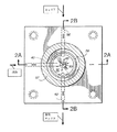
気化器12の詳細は、図2〜図5に示される。図2を参照すると、液体入力ポート30は、バルブ本体42を通る流路40によって、ピストン46を収容するバルブ孔(shut off valve bore)44に連結される。閉止バルブが閉じられた場合には、ピストン46は、(図2に示すように)バルブ孔44の内側面に抗して着座し、液体の流れを妨げる。いかなる好適な駆動手段も、この着座位置の内外に、バルブ孔44に沿ってバルブピストン46を移動するために使用することができる。一つの実施例において、ベローズスプリング45は、バルブ孔44に抗してピストン(seat piston)46に向かう押圧力を発生し、閉止バルブを閉じる。開口41を経由する空洞(cavity) 43内に圧縮空気を導入し、ピストン46に付勢力を発生し、かつ、このピストン46がバルブ孔44から外に移動することにより閉止バルブ(shut off valve) は開けられ、液体の流れを許容する。別のタイプのバルブ、例えばダイアフラムバルブ等も閉止バルブとして使用することができる。
【0017】
バルブ本体42内の通路或いは流路48は、バルブ孔44を制御バルブ孔50或いは空洞に連結している。制御バルブ孔50は、流路48終端の孔49の直前に位置する、圧電部材52とダイアフラム54とを有するピエゾ(piezo )バルブを収容している。圧電部材52の電気的励振は、ダイアフラム54を流路48の終端近くに、或いは終端から移動させ、これによって液体流量を制御する。
【0018】
ピエゾバルブは、たとばSTEC社製(京都)から入手可能なモデルIV100O、IV2000タイプのような、商業的に使用可能な圧電バルブと共に提供しても良い。一実施例として、そのバルブは、典型的には0.3−0.6g/minの流量で作動し、この場合、ダイアフラム54と孔49とのギャップは、おおよそ10μmである。(過度のギャップ長は制御バルブ孔50内で望ましくない故障(tuebarence) を引き起こす。)この実施例において、圧電バルブ(piezo−electric valve) は、例えば、0ボルトの入力電圧でギャップが0μm、5ボルトの入力電圧でギャップが10−15μm、また15ボルトの入力電圧でギャップが30μmのように、0−30μmのギャップ調整範囲を与えるように選定し得る。このように、圧電バルブは、流量制御を行うだけでなく、一時的に流量を完全に止めるためにも使用することが可能である。
【0019】
通常の圧電バルブは、例えば±15ボルトの電力を供給され、適切に動作する。通常、電力供給が停止された場合には、このバルブは全開状態まで弛緩する。このように、電気的な故障に対する保護のため、ピストン46によってもたらされるようなポジティブ閉止バルブ(positive shut off valve)に対して直列に圧電バルブを連結することが賢明である。一方、異なる比率の制御バルブ(different proportional control valve) は、ピエゾバルブの代用となることが可能であり、流量制御及びポジティブ閉止(positive shut off )の双方に使用することができる。
【0020】
図3及び図5によれば、ガス入力ポート36は、流路58により、バルブ本体42を経由して制御バルブ孔50と接続される。出力ポート60は、流路62によりバルブ本体42を経由して制御バルブ孔50と接続される。ハウジング57はダイアフラム54をバルブ本体42に接した状態に維持する。ダイアフラム54は円筒形のセンターピストン61を有しており、このセンターピストン61(図5)は弁座53の表面に並行で、かつ、この表面からの間隙(close space)を調整可能に位置される。ダイアフラム54は厚い環状エッジ63を有しており、この環状エッジ63はバルブ本体42に形成された円形の縁( circular lip)56上に載っている。ダイアフラム54はステンレススチール或いは類似の可撓性金属によって製造される。ダイアフラム54の可動“スパイダー(spider)”部59は、厚い環状エッジ63と円筒形のセンターピストン61とを連結する、薄い(例えば40−50ミリメートル)、弾力性のある環状シート或いは薄膜で構成される。輪状のOリングシール55はダイアフラム54の環状エッジ63と接しており、これにより制御バルブ孔50内に、蒸気/キャリア混合物を収容できる。
【0021】
図4は、制御バルブ孔50内の流路58と流路62との間に配設された孔49を示す。孔49は、制御バルブ孔50内において液流の集中を防止するために、十分に大きな径を有している(孔49があまりに小さい場合、ピエゾバルブでは、その流量をもはや調整することはできない)。図4の放射状の矢印は、オリィフス49から制御バルブ孔50内への、液体の流れの方向を示している。図4の円弧状の矢印は、流路58から環状の制御バルブ孔50の周辺に沿って流路62内へ向かう、キャリアガスの流れの方向を示している(この場所で、キャリアガスは気化された液体と混合される)。
【0022】
図4は、また、(図5を参照して以下に述べるように)ダイアフラム54の面とかみ合う(engage) 弁座53、ダイアフラム54の厚い環状エッジ63とかみ合う円形の縁56、及びハウジング57の円形のセンターエッジを図示している。
【0023】
図5を参照すると、動作中、TEOSのような液体反応物11は、たとえばおよそ2〜30psi(pounds per square inch) で、ソース24により加圧される (図1)。閉止バルブが開かれるとき(すなわち、図示されるように、ピストン46がバルブ孔44から引き出される)、その液体は液体入力ポート30に入り、流路(liquid inlet port)40、48を経由して流れる。そして、この反応物液体は、バルブ本体42から突出する孔49を含む弁座53とダイアフラム54との間の制御バルブ孔50内に形成される気化領域51に、孔49から注入される。弁座53の径が大き過ぎると、液体流量メータ14により測定される振動(oscillating)流量で検知され得る、不安定な気化(turbulent vaporization)が生じることが明らかにされた。一実施例として、その弁座の径はおよそ0.5cmである。また、弁座53と対をなすダイアフラム54の面の径が、弁座自体の径よりも大きい場合に、より効率的な気化が達成されることが明らかになった。一実施例として、これら2つの径の割合は、図5に示される通りである。気化領域51に注入される液体反応物11の量は、孔49に対するダイアフラム54の位置によって制御され、この位置は圧電部材52の電気的励起により順に制御される。
【0024】
流路48を出る際、液体反応物11は気化領域51内における放射状の圧力低下(radial pressure drop) に遭遇し(この圧力低下の勾配は図4の矢印により示される)、膨脹により気化する。(この種の勾配の圧力低下は、たとえばアトマイザーによって作り出される種類の階段状の圧力低下よりも、速さの点でより有効で、かつ、反応物液体をより均一に気化させることが分かった。) 気化領域51を出た後、気化された反応物液体は、流路(inlet passage)58から流路(outlet passage) 62に流れるキャリアガスと混合し、気化器12からCVDプロセスチャンバー18に輸送される(図1)。膨脹のために冷却された気化反応物液体が、制御バルブ孔50の壁上で液化させないように、この気化器は、加熱ジャケット(surrounding heating jacket:図示せず) により高温に維持される。
【0025】
ダイアフラム54の環状エッジ63上に下向きにかかる、ハウジング57からの圧力は、ダイアフラム54のセンターピストン61を、弁座53の表面から離れて上方に後退させることが、後述する図6において示されるであろう。電気的非励起が圧電部材52に与えられると、そのバルブは孔位置まで弛緩する(図2、3)。
【0026】
図5において示される実施例において、弁座53の表面は縁56の上面と同一面に位置する。したがって、制御バルブ孔(cavity) 50を横切って延びる、縁56の上面を表す線は、弁座53の上面を表す線と正確に同一直線上に位置する。
【0027】
図1の制御電子部32の詳細は図6に示される。ピエゾバルブの電圧対開口の変換機能を制御することは、その機能が非線形であり、履歴現象(hysteresis) を持ち、また温度、圧力及び流量の変化に伴って変動するために困難であり、このためピエゾパルブの制御にはフィードバック制御が用いられる。電子制御部32はPID制御回路72を含んでおり、この回路72はライン76と78との間の差分、この差分の積分、或いはこの差分の微分の各関数となる出力をライン80に発生する。このPID回路の入力−出力の関係は、回路の安定性とトラッキングが最大となるように、また、応答時間が最小となるように選択される。好適には、自動調整或いは適応性のある(adaptive filtered)PID回路は、その制御機能が連続して最適化されるために用いられる。例えば、部品番号965Aとして、Watlow Controls によって販売されるPID回路のような、商業的に利用できる適応性のあるPID回路も、図6のアプリケーションで好適に使用可能である。
【0028】
PID制御回路72に対する入力は、ライン76の液体流量モニターによって与えられる、0から5ボルトの出力信号、及びライン78の設定値信号(set point signal)である。PID回路72の出力は、ライン80のピエゾバルブに与えられる、0から5ボルトの位置入力信号である。PID制御回路72は、ライン76の流量モニターの出力信号をライン78の設定値信号に等しくするように、ライン80の位置入力信号を操作する。液体流量が所望のレベルを下回る場合には、ライン76の流量出力信号とライン78の設定値信号とが異なり、PID制御回路72は気化器12を操作して、圧電バルブを開けて液体流量を増加させる。また、液体流量が所望のレベルを上回る場合には、PID制御回路72は気化器12を操作して、圧電バルブを閉めて液体流量を低減させる。
【0029】
システム10は単純であり、容易に保守ができ、低コストでかつ改善されたプロセス制御を備えている。本発明の気化器12を用いることにより、液体流量制御と気化とが一段で行われる。その結果、蒸気流量、反復性及び応答性が改善され、液体流量及びキャリアガス流量の個別制御が達成できる。したがって、薄膜の特性を個別に制御することができる。
【0030】
当業者が、図示され或いは記載された本発明の形式及び細目に様々な変更を施すことは明らかであろう。例えば、液体流量(liquid mass flow) を液体の気化と別けて制御することも可能である。この目的を達成するため、図1の液体流量モニター12は、低圧力差を持った液体流量コントローラに変えてもよく、また、付加的な高温度モニターをライン47に挿入しても良い。この際、制御電子部は、液体流量コントローラの入力を操作して、液体流量を所望の量に制御する第1セクション、及び、高温度モニターによって発生された測定量に応じて気化器12におけるピエゾバルブの気化を制御する第2セクションの、分離されたセクションを含んでも良い。
【0031】
これらの実施例及び他のいかなる代わりの実施例も、記載された特許請求の範囲の精神及び範囲に含まれることを意図する。
【0032】
なお、各図上で認識できるように、より細い流路はその径を誇張して示している。
【0033】
【発明の効果】
本発明によれば、圧力勾配下の膨脹によりに蒸気を形成し、このため、多くの半導体製作プロセスで必要とされるような高流量で液体を気化することができる。また、液体の流量はダイアフラムの動きによって単独に制御され、このため液体の流量はキャリアガスの流量と独立であり、それゆえ、より正確に制御することが可能となる。
【図面の簡単な説明】
【図1】本発明にかかる液体分配システムを示すブロック図である。
【図2】図3の2A−2A線に沿う気化器の断面を示す断面図である。
【図3】図2の2B−2B線に沿う気化器の断面を示す断面図である。
【図4】蒸発器を示す平面図である。
【図5】気化器の要部を拡大して示す図である。
【図6】図1の液体分配システムを一部をより詳細に示すブロック図である。
【符号の説明】
10…液体分配システム、11…液体反応物、12…気化器、14…液体流量モニター、18…CVDプロセスチャンバー、30…液体入力ポート、32…制御電子部、36…ガス入力ポート、38…質量流量コントローラー、40、48、58、62…流路、42…バルブ本体、44…バルブ孔、46…ピストン、50…制御バルブ孔、52…圧電部材、53…弁座、54…ダイアフラム、60…出力ポート。[0001]
[Industrial application fields]
The present invention mainly relates to an apparatus for vaporizing a liquid at a controlled rate. More specifically, the present invention relates to an apparatus for vaporizing a liquid in a rapid pressure drop state and mixing the vaporized liquid and the carrier gas by a method of independently controlling the flow rates of the liquid and the carrier gas. The present invention is particularly suitable for supplying vaporized reactants to a reaction chamber of a chemical vapor deposition system.
[0002]
[Prior art]
Chemical vapor deposition (CVD) processes are widely used to form thin films used in semiconductor devices and integrated circuits. Such processes involve deposition that occurs as a result of the reaction of chemical vapors of the same or different materials on the substrate. This reaction rate is controlled by, for example, temperature, pressure, or the flow rate of the reaction gas. The use of low vapor pressure liquids as precursors for such processes has several advantages, and this method is becoming more common.
[0003]
[Problems to be solved by the invention]
Prior to the CVD process, a low vapor pressure liquid is transported using a bubbler or boiler. In this process, the carrier gas contains enough of the liquid to transport the vapor. The amount of vapor to be transported depends on the downstream pressure, the flow rate of the carrier gas, the vapor pressure in the ampoule containing the source liquid source, and the like. Thus, since the amount of vapor transported is not an independent parameter, its control is difficult. As a result, CVD processes using bubblers and boilers do not demonstrate the ability to consistently control the flow rate of vaporized reactants, which reduces the quality of the films produced by these processes. .
[0004]
An additional disadvantage of CVD processes using bubblers is that these processes are difficult to create the high reactant flow rates necessary to achieve high thin film deposition rates. In a bubbler, increasing the reactant flow rate requires either increasing the bubbler temperature or increasing the carrier gas flow rate. However, downstream hardware reliability limits the use of temperatures above a defined amount, and the adverse effects of excessive carrier gas flow rates on deposited film quality limit the use of large carrier gas flow rates. This limits the amount of steam that must be transported. Thus, the amount of reactant vapor to be transported is subject to undesired limits.
[0005]
In known boilers, the vapor formed when the liquid is heated is controlled using a hot gas flow controller. In this device configuration, the amount of steam transported depends on the downstream chamber pressure and boiler temperature. However, the vapor pressure of a typical liquid used for the deposition of a semiconductor film (eg, tetraethylorthosilane TEOS) is very low at normal operating temperatures. This results in limited vapor transport when the boiler is used in a high pressure (eg, atmospheric pressure) CVD process. Heating the boiler to the liquid boiling temperature can clearly improve vapor transport for such processes, but the boiler temperature is limited by the reliability of the downstream hardware.
[0006]
A previously filed US patent application (Application No. 07/912024) describes a CVD process that flows a heated carrier gas over a bead of liquid. Vapor is formed. The liquid vaporizes in the carrier gas, creating a reactant vapor for CVD. The vaporization rate is controlled by adjusting the flow rate of the liquid in the bead. That is, at large flow rates, the bead size and surface area increase until the vaporization rate is equal to the liquid flow rate. However, in the given limitations described above, increasing the liquid flow rate will be just partial vaporization. The advantage of this process over bubbler and boiler technology is that the liquid flow rate is uniquely controlled. However, like the bubbler and boiler technology, this technology relies on heated steam to vaporize the liquid and thus tends to produce a limited vaporization rate in the end.
[0007]
As a result, there remains a need for a reliable and lightly maintained liquid vaporizer that can vaporize liquid at high flow rates and, in addition, independently control the flow rates of liquid and carrier gas. The present invention is directed to this need.
[0008]
[Means for Solving the Problems]
The invention features a vaporizer that receives a carrier gas and a pressurized liquid. Internal cavities receive a carrier gas through a carrier aperture, and mix with the carrier gas vapor formed from a liquid received through a liquid aperture. The mixed gas and vapor are discharged from this hole through the third hole. This liquid is vaporized by the pressure difference between the liquid and the gas. In order to create a pressure gradient between the liquid hole and the remnant of the hole, a blocking element substantially larger than the liquid hole is arranged adjacent to the liquid hole. The liquid passing through this pressure gradient is vaporized for expansion.
[0009]
An advantage of the present invention is that the vapor is formed by expansion under a pressure gradient rather than evaporation due to heating , thus allowing the liquid to vaporize at a high flow rate as required in many semiconductor fabrication processes. It can be done.
[0010]
In a preferred embodiment, the blocking element is a movable diaphragm adjacent to the liquid hole to increase or decrease the liquid flow path. This blocking element is moved by an electrically controlled actuator, such as a piezoelectric element. A liquid flow meter is connected to control the liquid flow rate and measures the liquid flow rate in the liquid input port. The feedback control system compares the measured flow rate with the selected value, and controls the piezoelectric actuator so that the flow rate approaches the selected value.
[0011]
The advantage of this invention is that the liquid flow rate is independently controlled by the movement of the diaphragm, so that the liquid flow rate is independent of the carrier gas flow rate (as opposed to the conventional vaporization system described above). Yes, and therefore can be controlled more accurately.
[0012]
In a further preferred embodiment, after the liquid is vaporized, at least the valve body in the vicinity of the hole is heated with a heating device in order to prevent the liquid cooled for expansion from liquefying on the wall in the hole. .
[0013]
【Example】
Referring now to the drawings in more detail, FIG. 1 shows a liquid delivery system using a
[0014]
The liquid bulk distribution tank 16 has a
[0015]
In many applications, the liquid reactant 11 may be toxic and / or caustic. In order to facilitate servicing of the
A remotely controllable (eg pneumatic)
[0016]
Details of the
[0017]
A passage or flow
[0018]
Piezo valves may be provided with commercially available piezoelectric valves, such as models IV100O, IV2000 types, for example, available from STEC (Kyoto). As an example, the valve typically operates at a flow rate of 0.3-0.6 g / min, where the gap between
[0019]
A normal piezoelectric valve is supplied with power of, for example, ± 15 volts and operates properly. Normally, when the power supply is stopped, this valve relaxes to the fully open state. Thus, for protection against electrical failure, it is advisable to connect a piezoelectric valve in series with a positive shut off valve as provided by the piston 46. On the other hand, different proportion control valves can be substituted for piezo valves and can be used for both flow control and positive shut off.
[0020]
According to FIGS. 3 and 5, the
[0021]
FIG. 4 shows a
[0022]
4 also engages the face of the diaphragm 54 (as described below with reference to FIG. 5), the
[0023]
Referring to FIG. 5, during operation, a liquid reactant 11 such as TEOS is pressurized by a
[0024]
Upon exiting the
[0025]
The pressure from the
[0026]
In the embodiment shown in FIG. 5, the surface of the
[0027]
Details of the
[0028]
The inputs to the
[0029]
[0030]
It will be apparent to those skilled in the art that various modifications may be made to the form and details of the invention as illustrated or described. For example, the liquid mass flow can be controlled separately from the vaporization of the liquid. To achieve this goal, the liquid flow monitor 12 of FIG. 1 may be replaced with a liquid flow controller with a low pressure differential, and an additional high temperature monitor may be inserted in
[0031]
These embodiments and any other alternative embodiments are intended to be included within the spirit and scope of the appended claims.
[0032]
In addition, as can be recognized on each figure, the diameter of the narrower channel is exaggerated.
[0033]
【The invention's effect】
In accordance with the present invention, vapor is formed by expansion under a pressure gradient, and thus the liquid can be vaporized at a high flow rate as required in many semiconductor fabrication processes. Also, the flow rate of the liquid is independently controlled by the movement of the diaphragm, so that the flow rate of the liquid is independent of the flow rate of the carrier gas and therefore can be controlled more accurately.
[Brief description of the drawings]
FIG. 1 is a block diagram showing a liquid distribution system according to the present invention.
2 is a cross-sectional view showing a cross section of the vaporizer taken along
3 is a cross-sectional view showing a cross section of the vaporizer along
FIG. 4 is a plan view showing an evaporator.
FIG. 5 is an enlarged view showing a main part of the vaporizer.
6 is a block diagram showing a portion of the liquid dispensing system of FIG. 1 in more detail.
[Explanation of symbols]
DESCRIPTION OF
Claims (39)
第一の孔及び第三の孔を有する制御バルブ空孔を画定するバルブ本体と、
ある流速で液体が通って流れる第二の孔が中に形成されたバルブ弁座であって、前記第二の孔は中央軸を有するものである、前記バルブ弁座と、
前記キャリアガスを受け入れるためのガス入力ポートであって、前記第一の孔に第一の流体流路を介して接続された、前記ガス入力ポートと、
液体を受け入れるための液体入力ポートであって、前記第二の孔に第二の流体流路を介して接続された、前記液体入力ポートと、
前記バルブ弁座に隣接して且つその反対側に配置され、前記第二の孔を外接するバルブ領域を形成しているバルブ要素を含むバルブ機構であって、前記バルブ領域は、前記中央軸から半径方向に測定された場合には前記第二の孔よりも大きな幅を有しており、前記バルブ要素は、前記第二の孔を出た液体の前記バルブ空孔内への流速を可変制御するように、全閉位置と全開位置を含み且つそれらの間の連続的な設定範囲にわたって、前記バルブ機構によって連続的に調節可能である、前記バルブ機構と、
第三の流体流路を介して前記第三の孔に接続されている、バルブ本体の出力ポートであって、操作中には、前記液体入力ポートを介して供給された液体が、前記第二の孔を介して注入され、第二の孔の中央軸から離れて放射状に流れ、前記バルブ空孔内で気化し、前記キャリアガスと混合され、前記出力ポートを介して前記気化器の外へ運ばれる、前記出力ポートと、
を備える、前記気化器。A vaporizer for vaporizing a liquid and mixing the vaporized liquid with a carrier gas,
A valve body defining a control valve cavity having a first hole and a third hole;
A valve valve seat having a second hole formed therein in which a liquid flows at a flow rate, the second hole having a central axis;
A gas input port for receiving the carrier gas, the gas input port connected to the first hole via a first fluid flow path;
A liquid input port for receiving liquid, the liquid input port connected to the second hole via a second fluid flow path;
A valve mechanism including a valve element disposed adjacent to and opposite to the valve valve seat and forming a valve area circumscribing the second hole, wherein the valve area extends from the central shaft; The valve element has a larger width than the second hole when measured in the radial direction, and the valve element variably controls the flow rate of the liquid exiting the second hole into the valve hole. The valve mechanism including a fully closed position and a fully open position and is continuously adjustable by the valve mechanism over a continuous set range therebetween;
An output port of the valve body connected to the third hole via a third fluid flow path, wherein during operation the liquid supplied via the liquid input port is Injected through the second hole, flows radially away from the central axis of the second hole, vaporizes in the valve cavity, mixes with the carrier gas, and out of the vaporizer through the output port. The output port carried; and
Comprising the vaporizer.
前記第二の孔から出る液体の流速を測定するために接続された液体流量計と、
前記液体流量計によって測定された流速に応答して前記制御信号を発生させるフィードバック制御システムと、
を更に備える、前記気化器。A vaporizer according to claim 12, comprising:
A liquid flow meter connected to measure the flow rate of the liquid exiting the second hole;
A feedback control system for generating the control signal in response to a flow rate measured by the liquid flow meter;
The vaporizer further comprising:
第一の孔、ある流速で液体が通って流れる第二の孔、及び第三の孔を有する制御バルブ空孔を画定するバルブ本体であって、前記第二の孔は中央軸を有するものである、前記バルブ本体と、
第二の孔が内部に形成されているバルブ弁座と、
前記キャリアガスを受け入れるガス入力ポートであって、第一の流体流路を介して前記第一の孔に接続されている、前記ガス入力ポートと、
液体反応物を受け入れる液体入力ポートであって、第二の流体流路を介して前記第二の孔に接続されている、前記液体入力ポートと、
バルブ弁座に隣接して配置され、前記第二の孔を外接するバルブ領域を形成しているバルブ要素を含むバルブ機構であって、前記バルブ領域は、前記中央軸から半径方向に測定された場合には前記第二の孔よりも大きな幅を有しており、前記バルブ要素は、前記第二の孔を出た液体反応物の前記バルブ空孔内への流速を可変制御するように、全閉位置と全開位置を含み且つそれらの間の連続的な設定範囲にわたって、前記バルブ機構によって連続的に調節可能である、前記バルブ機構と、
第三の流体流路を介して前記第三の孔に接続されている出力ポートであって、操作中には、前記液体入力ポートを介して供給された液体が、前記第二の孔を介して注入され、第二の孔の中央軸から離れて放射状に流れ、前記バルブ空孔内で気化し、前記キャリアガスと混合され、前記出力ポートを介して前記気化器の外へ運ばれる、前記出力ポートと、
を備える、化学気相堆積システム。A chemical vapor deposition system using a liquid reactant and a carrier gas, comprising: a chemical vapor deposition chamber having a gas input port; and a liquid reactant vaporizer having an output port connected to the chamber input port. The vaporizer comprises:
A valve body defining a control valve cavity having a first hole, a second hole through which liquid flows at a flow rate, and a third hole, the second hole having a central axis. A valve body,
A valve seat with a second hole formed therein;
A gas input port for receiving the carrier gas, the gas input port connected to the first hole via a first fluid flow path;
A liquid input port for receiving a liquid reactant, the liquid input port connected to the second hole via a second fluid flow path; and
A valve mechanism disposed adjacent to a valve valve seat and forming a valve region circumscribing the second hole, wherein the valve region is measured radially from the central axis In some cases has a width greater than the second hole, and the valve element variably controls the flow rate of liquid reactant exiting the second hole into the valve hole, The valve mechanism including a fully closed position and a fully open position and is continuously adjustable by the valve mechanism over a continuous set range therebetween;
An output port connected to the third hole via a third fluid flow path, wherein during operation, the liquid supplied via the liquid input port passes through the second hole; Injecting and flowing radially away from the central axis of the second hole, evaporating in the valve cavity, mixed with the carrier gas and carried out of the vaporizer through the output port, An output port;
A chemical vapor deposition system comprising:
第一の孔及び第三の孔を有する制御バルブ空孔を画定するバルブ本体を提供するステップと、
第二の孔が内部に形成されたバルブ弁座であって前記第二の孔は中央軸を有するものを提供するステップと、
前記第二の孔を外接するバルブ領域を形成するように、前記バルブ弁座に隣接して且つその反対側に配置されたバルブ要素を含むバルブ機構を提供するステップであって、前記バルブ領域は、前記中央軸から半径方向に測定された場合には前記第二の孔よりも大きな幅を有している、前記ステップと、
第一の孔に第一の流体流路を介してキャリアガスを供給するステップと、
前記第二の孔に第二の流路を介して液体を供給するステップと、
調節可能な流速で、バルブ領域内へと第二の孔を介して液体を注入するステップと、
前記第二の孔から出てバルブ領域内へ入る液体の調節可能な流速を、バルブ弁座とバルブ要素との間の分離を調節することによって、連続的に可変な方法で制御するステップと、
第二の孔を介してバルブ領域に供給される液体を気化させるステップと、
前記バルブ領域からの気化された液体をキャリアガスと混合させて混合物を形成させるステップと、
第三の流路を介して出力ポートにデリバリーするために、混合物を前記第三の孔を介して外に通すステップと、
を含む、前記方法。A method for vaporizing a liquid and mixing the vaporized liquid with a carrier gas,
Providing a valve body defining a control valve cavity having a first hole and a third hole;
Providing a valve seat with a second bore formed therein, wherein the second bore has a central axis;
Providing a valve mechanism including a valve element disposed adjacent to and opposite the valve valve seat to form a valve region circumscribing the second hole, the valve region comprising: The step has a larger width than the second hole when measured radially from the central axis, and
Supplying a carrier gas to the first hole via the first fluid flow path;
Supplying liquid to the second hole via a second flow path;
Injecting liquid through the second hole into the valve region at an adjustable flow rate;
Controlling the adjustable flow rate of liquid exiting the second hole and entering the valve region in a continuously variable manner by adjusting the separation between the valve seat and the valve element;
Vaporizing liquid supplied to the valve region through the second hole;
Mixing the vaporized liquid from the valve region with a carrier gas to form a mixture;
Passing the mixture out through the third hole for delivery to the output port via the third flow path;
Said method.
内部に形成された第一の孔及び第三の孔を有するバルブ本体であって、第二の孔が内部に形成されているバルブ弁座を有する前記バルブ本体と、
バルブ本体に形成され且つ第一の流体流路を介して第一の孔に接続されているガス入力ポートと、
バルブ本体に形成され且つ第二の流体流路を介して第一の孔に接続されている液体入力ポートと、
第二の孔及びバルブ弁座に隣接して且つ反対側に、それらとの間に容積を画定するために配置された圧電部材及びダイアフラムを備える圧電性バルブであって、比率制御バルブの位置は、全閉位置から全開位置までの連続的な設定範囲にわたって連続的に調節可能である、前記圧電性バルブと、
第三の流体流路を介して第三の孔に接続されている、バルブ本体の出力ポートと、
を備え、比率制御バルブの位置が、第二の孔から容積内に入る液体の膨張によって気化が生じるように気化領域内の圧力勾配が充分であるよう調整可能であり、且つ、ダイアフラムの直径がバルブ弁座の直径よりも大きい、前記気化器。A vaporizer for vaporizing a liquid and mixing the vaporized liquid with a carrier gas,
A valve body having a first hole and a third hole formed therein, the valve body having a valve valve seat in which a second hole is formed;
A gas input port formed in the valve body and connected to the first hole via the first fluid flow path;
A liquid input port formed in the valve body and connected to the first hole via a second fluid flow path;
A piezoelectric valve comprising a piezoelectric member and a diaphragm disposed adjacent to and opposite to the second hole and valve valve seat to define a volume therebetween, wherein the ratio control valve is positioned The piezoelectric valve is continuously adjustable over a continuous set range from the fully closed position to the fully open position; and
An output port of the valve body connected to the third hole via a third fluid flow path;
The position of the ratio control valve can be adjusted so that the pressure gradient in the vaporization region is sufficient so that vaporization occurs due to the expansion of the liquid entering the volume from the second hole, and the diameter of the diaphragm is The carburetor larger than the diameter of the valve seat.
内部に形成された第一の孔及び第三の孔を有するバルブ本体を提供するステップであって、前記バルブ本体は第二の孔が内部に形成されているバルブ弁座を有するものである、前記ステップと、
バルブ本体にガス入力ポートを提供するステップであって、ガス入力ポートは第一の孔と流体連絡している第一の流体流路に接続されているものである、前記ステップと、
ガス入力ポートから第一の流体流路を介して第一の孔にキャリアガスを供給するステップと、
バルブ本体に液体入力ポートを提供するステップであって、液体入力ポートは第二の孔と流体連絡している第二の流体流路に接続されているものである、前記ステップと、
液体入力ポートから第二の流体流路を介して第二の孔に、ある流速で、液体を供給するステップと、
フィードバック制御を使って液体の流速を制御するステップと、
バルブ本体に出力ポートを提供するステップであって、出力ポートは第三の流体流路を介して第三の孔に接続されているものである、前記ステップと、
バルブ弁座に隣接して且つ反対側に、それとの間に容積を画定するために比率制御バルブを配置するステップと、
全閉位置から全開位置までの連続的な設定範囲にわたって、連続的に可変な方法で、比率制御バルブの位置を調節して、第二の孔から出る液体の流出速度及び第二の孔と容積との間の圧力勾配を可変制御するステップであって、第二の孔から容積内に入る液体の膨張によって気化が生じるよう気化領域内の圧力勾配を充分にする前記ステップと、
気化された液体をキャリアガスと混合するステップと、
混合された、気化された液体及びキャリアガスを、第三の孔を介し、第三の流体流路を介し、そして出力ポートを介して、気化領域から外へ排出させるステップと、
を含む、前記方法。A method for vaporizing a liquid and mixing the vaporized liquid with a carrier gas,
Providing a valve body having a first hole and a third hole formed therein, the valve body having a valve valve seat having a second hole formed therein; Said step;
Providing a gas input port to the valve body, wherein the gas input port is connected to a first fluid flow path in fluid communication with the first hole;
Supplying a carrier gas from the gas input port to the first hole via the first fluid flow path;
Providing a liquid input port to the valve body, wherein the liquid input port is connected to a second fluid flow path in fluid communication with the second bore;
Supplying liquid at a flow rate from the liquid input port to the second hole via the second fluid flow path;
Controlling the flow rate of the liquid using feedback control;
Providing an output port to the valve body, wherein the output port is connected to the third hole via a third fluid flow path; and
Placing a ratio control valve adjacent to and opposite to the valve valve seat to define a volume therebetween;
Adjusting the position of the ratio control valve in a continuously variable manner over a continuous set range from the fully closed position to the fully open position, the liquid outflow rate and the second hole and volume from the second hole Variably controlling the pressure gradient between and wherein the pressure gradient in the vaporization region is sufficient to cause vaporization due to expansion of liquid entering the volume from the second hole;
Mixing the vaporized liquid with a carrier gas;
Draining the mixed vaporized liquid and carrier gas out of the vaporization region through the third hole, through the third fluid flow path, and through the output port;
Said method.
液体流量モニターを、液体バルクデリバリータンクとバルブ本体の液体入力ポートとの間に接続するステップと、
気化器の液体流量制御入力を提供するステップと、
液体流量モニターからの制御信号を、電子システムを介して、液体流量制御入力へ送るステップと、
質量流量コントローラを、キャリアガスタンクとバルブ本体のガス入力ポートとの間に接続するステップと、
を含む、請求項25に記載の方法。The step of using feedback control is
Connecting a liquid flow monitor between the liquid bulk delivery tank and the liquid input port of the valve body;
Providing a liquid flow control input for the vaporizer;
Sending a control signal from a liquid flow monitor via an electronic system to a liquid flow control input;
Connecting a mass flow controller between the carrier gas tank and the gas input port of the valve body;
26. The method of claim 25, comprising:
液体流量モニターからの流量出力信号を供給するステップと、
設定値信号を提供するステップと、
比率−積分−微分制御回路を使って、流量出力信号と設定値信号との差、該差の積分値、及び、該差の微分値の関数である出力を発生させるステップと、
液体流量モニターを介しての液体流速が所望レベル以下である場合には、比率−積分−微分制御回路を使って、比率制御バルブを操作するステップと、
液体流速が所望レベルを超える場合には、比率−積分−微分制御回路を使って、比率制御バルブを遮断するステップと、
を含む、請求項26に記載の方法。Sending the control signal comprises:
Providing a flow output signal from the liquid flow monitor;
Providing a setpoint signal;
Using a ratio-integral-derivative control circuit to generate a difference between the flow rate output signal and the setpoint signal, an integral value of the difference, and an output that is a function of the differential value of the difference;
Operating a ratio control valve using a ratio-integral-derivative control circuit if the liquid flow rate through the liquid flow monitor is below a desired level;
If the liquid flow rate exceeds the desired level, using a ratio-integral-derivative control circuit to shut off the ratio control valve;
27. The method of claim 26, comprising:
低い圧力差を有する液体質量流量コントローラを提供するステップと、
高温モニターを、気化器の出力に接続させるステップと、
液体質量流量コントローラの入力を駆動することによって液体質量流量を所望値に制御するための第一のセクションと、高温モニターによって生じた測定値に応じて比率制御バルブで気化を制御するための第二のセクションとを含む電子システムを提供するステップと、
を含む、請求項26に記載の方法。Sending the control signal comprises:
Providing a liquid mass flow controller having a low pressure differential;
Connecting a high temperature monitor to the vaporizer output;
A first section for controlling the liquid mass flow to the desired value by driving the input of the liquid mass flow controller, and a second for controlling the vaporization with a ratio control valve in response to the measurement produced by the high temperature monitor. Providing an electronic system comprising:
27. The method of claim 26, comprising:
内部に形成された第一の孔及び第三の孔を有するバルブ本体であって、第二の孔が内部に形成されているバルブ弁座を有する前記バルブ本体と、
バルブ本体に形成され且つ第一の流体流路を介して第一の孔に接続されているガス入力ポートと、
バルブ本体に形成され且つ第二の流体流路を介して第一の孔に接続されている液体入力ポートと、
第二の孔及びバルブ弁座に隣接して且つ反対側に、それらとの間に容積を画定するために配置された比率制御バルブであって、その位置は、全閉位置から全開位置までの連続的な設定範囲にわたって連続的に調節可能である、前記比率制御バルブと、
第三の流体流路を介して第三の孔に接続されている、バルブ本体の出力ポートと、
気化器に接続されたフィードバック制御であって、
液体バルクデリバリータンクとバルブ本体の液体入力ポートとの間に接続された液体流量モニターと、
気化器の液体流量制御入力と、
液体流量モニターからの制御信号を液体流量制御入力へ送るための電子システムと、
キャリアガスタンクとバルブ本体のガス入力ポートとの間に接続された質量流量コントローラと、を備える前記フィードバック制御と、
を備える、前記気化器。A vaporizer for vaporizing a liquid and mixing the vaporized liquid with a carrier gas,
A valve body having a first hole and a third hole formed therein, the valve body having a valve valve seat in which a second hole is formed;
A gas input port formed in the valve body and connected to the first hole via the first fluid flow path;
A liquid input port formed in the valve body and connected to the first hole via a second fluid flow path;
A ratio control valve located adjacent to and opposite the second hole and valve valve seat to define a volume therebetween, the position being from a fully closed position to a fully open position; The ratio control valve being continuously adjustable over a continuous set range;
An output port of the valve body connected to the third hole via a third fluid flow path;
Feedback control connected to the vaporizer,
A liquid flow monitor connected between the liquid bulk delivery tank and the liquid input port of the valve body;
A liquid flow control input for the vaporizer,
An electronic system for sending control signals from the liquid flow monitor to the liquid flow control input;
A mass flow controller connected between the carrier gas tank and the gas input port of the valve body; and the feedback control comprising:
Comprising the vaporizer.
比率−積分−微分制御回路と、
液体流量モニターによって供給される流量出力信号と、
設定値信号と、を備え、
比率−積分−微分制御回路が、流量出力信号と設定値信号との差、該差の積分値、及び、該差の微分値の関数である出力を発生させるよう操作され、
液体流量モニターを介しての液体流速が所望レベル以下である場合には、比率−積分−微分制御回路が比率制御バルブを開放し、
液体流速が所望レベルを超える場合には、比率−積分−微分制御回路が比率制御バルブを遮断する、請求項29に記載の気化器。An electronic system to send control signals,
A ratio-integral-derivative control circuit;
A flow output signal supplied by the liquid flow monitor; and
A setpoint signal,
A ratio-integral-derivative control circuit is operated to generate an output that is a function of a difference between the flow rate output signal and the setpoint signal, an integral value of the difference, and a differential value of the difference;
If the liquid flow rate through the liquid flow monitor is below the desired level, the ratio-integral-derivative control circuit opens the ratio control valve,
30. The vaporizer of claim 29, wherein the ratio-integral-derivative control circuit shuts off the ratio control valve when the liquid flow rate exceeds a desired level.
内部に形成された第一の孔及び第三の孔を有するバルブ本体であって、第二の孔が内部に形成されているバルブ弁座を有する前記バルブ本体と、
バルブ本体に形成され且つ第一の流体流路を介して第一の孔に接続されているガス入力ポートと、
バルブ本体に形成され且つ第二の流体流路を介して第一の孔に接続されている液体入力ポートと、
第二の孔及びバルブ弁座に隣接して且つ反対側に、それらとの間に容積を画定するために配置された比率制御バルブであって、その位置は、全閉位置から全開位置までの連続的な設定範囲にわたって連続的に調節可能である、前記比率制御バルブと、
第三の流体流路を介して第三の孔に接続されている、バルブ本体の出力ポートと、
気化器に接続されたフィードバック制御であって、
低い圧力差を有する液体質量流量コントローラと、
気化器の出力に接続された高温モニターと、
液体質量流量コントローラを駆動することによって液体質量流量を所望値に制御するための第一のセクションと、高温モニターによって生じた測定値に応じて比率制御バルブで気化を制御するための第二のセクションとを含む、制御信号を送るための電子システムと、を備える前記フィードバック制御と、
を備える、前記気化器。A vaporizer for vaporizing a liquid and mixing the vaporized liquid with a carrier gas,
A valve body having a first hole and a third hole formed therein, the valve body having a valve valve seat in which a second hole is formed;
A gas input port formed in the valve body and connected to the first hole via the first fluid flow path;
A liquid input port formed in the valve body and connected to the first hole via a second fluid flow path;
A ratio control valve located adjacent to and opposite the second hole and valve valve seat to define a volume therebetween, the position being from a fully closed position to a fully open position; The ratio control valve being continuously adjustable over a continuous set range;
An output port of the valve body connected to the third hole via a third fluid flow path;
Feedback control connected to the vaporizer,
A liquid mass flow controller with a low pressure differential;
A high temperature monitor connected to the vaporizer output;
A first section for controlling the liquid mass flow to the desired value by driving the liquid mass flow controller, and a second section for controlling the vaporization with a ratio control valve in response to the measurement produced by the high temperature monitor An electronic system for sending a control signal, comprising:
Comprising the vaporizer.
内部に形成された第一の孔及び第三の孔を有するバルブ本体であって、その一部として組み込まれたバルブ弁座を更に有しており、該バルブ弁座は、その内部に形成された第二の孔を有する、前記バルブ本体と、
キャリアガスを受け入れるガス入力ポートであって、第一の流体流路を介して第一の孔に接続された、前記ガス入力ポートと、
バルブ本体内に形成され、且つ、第二の流体流路を介して第二の孔に接続された、液体入力ポートと、
バルブ弁座に隣接してそれとの間に容積を画定するように配置された圧電性バルブを含むバルブ機構であって、圧電性バルブは圧電部材及びダイアフラムを備えており、圧電性バルブの位置が、全閉位置から全開位置までの連続的な設定範囲にわたって、バルブ機構によって連続的に調節可能である、前記バルブ機構と、を備えるものであり、
出力ポートが第三の流体流路を介して第三の孔に接続されており、ダイアフラムの直径がバルブ弁座の直径よりも大きい、
前記化学気相堆積システム。A chemical vapor deposition system using a liquid reactant and a carrier gas, comprising: a chemical vapor deposition chamber having a chamber input port; and a liquid reactant vaporizer having an output port connected to the chamber input port. The vaporizer is
A valve body having a first hole and a third hole formed therein, further including a valve valve seat incorporated as a part thereof, wherein the valve valve seat is formed in the valve body. Said valve body having a second hole;
A gas input port for receiving a carrier gas, the gas input port connected to the first hole via a first fluid flow path;
A liquid input port formed in the valve body and connected to the second hole via a second fluid flow path;
A valve mechanism including a piezoelectric valve disposed adjacent to and defining a volume between a valve valve seat, the piezoelectric valve comprising a piezoelectric member and a diaphragm, wherein the position of the piezoelectric valve is The valve mechanism is capable of being continuously adjusted by the valve mechanism over a continuous set range from the fully closed position to the fully open position.
The output port is connected to the third hole via a third fluid flow path, the diameter of the diaphragm being larger than the diameter of the valve valve seat;
The chemical vapor deposition system.
内部に形成された第一の孔及び第三の孔を有するバルブ本体であって、その一部として組み込まれたバルブ弁座を更に有しており、該バルブ弁座はその内部に形成された第二の孔を有し、出力ポートが第三の流体流路を介して第三の孔に接続されている、前記バルブ本体と、
キャリアガスを受け入れるガス入力ポートであって、第一の流体流路を介して第一の孔に接続された、前記ガス入力ポートと、
バルブ本体内に形成され、且つ、第二の流体流路を介して第二の孔に接続された、液体入力ポートと、
バルブ弁座に隣接してそれとの間に容積を画定するように配置された比率制御バルブを含むバルブ機構であって、比率制御バルブの位置が、全閉位置から全開位置までの連続的な設定範囲にわたって、バルブ機構によって連続的に調節可能である、前記バルブ機構と、
気化器に接続されたフィードバック制御であって、
液体バルクデリバリータンクとバルブ本体の液体入力ポートとの間に接続された液体流量モニターと、
気化器の液体流量制御入力と、
液体流量モニターからの制御信号を液体流量制御入力へ送るための電子システムと、
キャリアガスタンクとバルブ本体のガス入力ポートとの間に接続された質量流量コントローラと、を備える、前記フィードバック制御と、
を備える、
前記化学気相堆積システム。A chemical vapor deposition system using a liquid reactant and a carrier gas, comprising: a chemical vapor deposition chamber having a chamber input port; and a liquid reactant vaporizer having an output port connected to the chamber input port. The vaporizer is
A valve body having a first hole and a third hole formed therein, further including a valve valve seat incorporated as a part thereof, wherein the valve valve seat is formed therein. The valve body having a second hole and an output port connected to the third hole via a third fluid flow path;
A gas input port for receiving a carrier gas, the gas input port connected to the first hole via a first fluid flow path;
A liquid input port formed in the valve body and connected to the second hole via a second fluid flow path;
A valve mechanism including a ratio control valve positioned adjacent to and defining a volume between the valve valve seat, wherein the position of the ratio control valve is set continuously from a fully closed position to a fully open position Said valve mechanism being continuously adjustable by a valve mechanism over a range;
Feedback control connected to the vaporizer,
A liquid flow monitor connected between the liquid bulk delivery tank and the liquid input port of the valve body;
A liquid flow control input for the vaporizer,
An electronic system for sending control signals from the liquid flow monitor to the liquid flow control input;
A mass flow controller connected between a carrier gas tank and a gas input port of the valve body, and the feedback control,
Comprising
The chemical vapor deposition system.
比率−積分−微分制御回路と、
液体流量モニターによって供給される流量出力信号と、
設定値信号と、を備え、
比率−積分−微分制御回路が、流量出力信号と設定値信号との差、該差の積分値、及び、該差の微分値の関数である出力を発生させるよう操作され、
液体流量モニターを介しての液体流速が所望レベル以下である場合には、比率−積分−微分制御回路が比率制御バルブを開放し、
液体流速が所望レベルを超える場合には、比率−積分−微分制御回路が比率制御バルブを遮断する、請求項33に記載の気化器。An electronic system to send control signals,
A ratio-integral-derivative control circuit;
A flow output signal supplied by the liquid flow monitor; and
A setpoint signal,
A ratio-integral-derivative control circuit is operated to generate an output that is a function of a difference between the flow rate output signal and the setpoint signal, an integral value of the difference, and a differential value of the difference;
If the liquid flow rate through the liquid flow monitor is below the desired level, the ratio-integral-derivative control circuit opens the ratio control valve,
34. The vaporizer of claim 33, wherein the ratio-integral-derivative control circuit shuts off the ratio control valve when the liquid flow rate exceeds a desired level.
内部に形成された第一の孔及び第三の孔を有するバルブ本体であって、その一部として組み込まれたバルブ弁座を更に有しており、該バルブ弁座は、その内部に形成された第二の孔を有し、出力ポートが第三の流体流路を介して第三の孔に接続されている、前記バルブ本体と、
キャリアガスを受け入れるガス入力ポートであって、第一の流体流路を介して第一の孔に接続された、前記ガス入力ポートと、
バルブ本体内に形成され、且つ、第二の流体流路を介して第二の孔に接続された、液体入力ポートと、
バルブ弁座に隣接してそれとの間に容積を画定するように配置された比率制御バルブを含むバルブ機構であって、比率制御バルブの位置が、全閉位置から全開位置までの連続的な設定範囲にわたって、バルブ機構によって連続的に調節可能である、前記バルブ機構と、
気化器に接続されたフィードバック制御であって、
低い圧力差を有する液体質量流量コントローラと、
気化器の出力に接続された高温モニターと、
液体質量流量コントローラの入力を駆動することによって液体質量流量を所望値に制御するための第一のセクションと、高温モニターによって生じた測定値に応じて比率制御バルブで気化を制御するための第二のセクションとを含む制御信号を送るための電子システムと、を備える、前記フィードバック制御と、
を備える、前記化学気相堆積システム。A chemical vapor deposition system using a liquid reactant and a carrier gas, comprising: a chemical vapor deposition chamber having a chamber input port; and a liquid reactant vaporizer having an output port connected to the chamber input port. The vaporizer is
A valve body having a first hole and a third hole formed therein, further including a valve valve seat incorporated as a part thereof, wherein the valve valve seat is formed in the valve body. The valve body having a second hole and an output port connected to the third hole via a third fluid flow path;
A gas input port for receiving a carrier gas, the gas input port connected to the first hole via a first fluid flow path; and
A liquid input port formed in the valve body and connected to the second hole via a second fluid flow path;
A valve mechanism including a ratio control valve positioned adjacent to and defining a volume between the valve valve seat, wherein the position of the ratio control valve is set continuously from a fully closed position to a fully open position Said valve mechanism being continuously adjustable by a valve mechanism over a range;
Feedback control connected to the vaporizer,
A liquid mass flow controller with a low pressure differential;
A high temperature monitor connected to the vaporizer output;
A first section for controlling the liquid mass flow to the desired value by driving the input of the liquid mass flow controller, and a second for controlling the vaporization with a ratio control valve in response to the measurement produced by the high temperature monitor. An electronic system for sending a control signal comprising a section of the feedback control, and
Said chemical vapor deposition system.
内部に形成された第一の孔及び第三の孔を有するバルブ本体であって、第二の孔が内部に形成されているバルブ弁座を有する前記バルブ本体と、
バルブ本体に形成され且つ第一の流体流路を介して第一の孔に接続されているガス入力ポートと、
バルブ本体に形成され且つ第二の流体流路を介して第一の孔に接続されている液体入力ポートと、
第二の孔及びバルブ弁座に隣接して且つ反対側に、それらとの間に容積を画定するように配置された圧電性バルブであって、その位置は、全閉位置から全開位置までの連続的な設定範囲にわたって連続的に調節可能である、前記圧電性バルブと、
第三の流体流路を介して第三の孔に接続されている、バルブ本体の出力ポートと、
気化器に接続されたフィードバック制御と、
を備える、前記気化器。A vaporizer for vaporizing a liquid and mixing the vaporized liquid with a carrier gas,
A valve body having a first hole and a third hole formed therein, the valve body having a valve valve seat in which a second hole is formed;
A gas input port formed in the valve body and connected to the first hole via the first fluid flow path;
A liquid input port formed in the valve body and connected to the first hole via a second fluid flow path;
A piezoelectric valve disposed adjacent to and opposite to the second hole and valve valve seat to define a volume therebetween, the position being from a fully closed position to a fully open position; The piezoelectric valve being continuously adjustable over a continuous set range;
An output port of the valve body connected to the third hole via a third fluid flow path;
Feedback control connected to the vaporizer,
Comprising the vaporizer.
液体バルクデリバリータンクとバルブ本体の液体入力ポートとの間に接続された液体流量モニターと、
気化器の液体流量制御入力と、
液体流量モニターからの制御信号を液体流量制御入力へ送るための電子システムと、
キャリアガスタンクとバルブ本体のガス入力ポートとの間に接続された質量流量コントローラと、
を備える、請求項36に記載の気化器。Feedback control
A liquid flow monitor connected between the liquid bulk delivery tank and the liquid input port of the valve body;
A liquid flow control input for the vaporizer,
An electronic system for sending control signals from the liquid flow monitor to the liquid flow control input;
A mass flow controller connected between the carrier gas tank and the gas input port of the valve body;
38. The vaporizer of claim 36, comprising:
比率−積分−微分制御回路と、
液体流量モニターによって供給される流量出力信号と、
設定値信号と、を備え、
比率−積分−微分制御回路が、流量出力信号と設定値信号との差、該差の積分値、及び、該差の微分値の関数である出力を発生させるよう操作され、
液体流量モニターを介しての液体流速が所望レベル以下である場合には、比率−積分−微分制御回路が比率制御バルブを開放し、
液体流速が所望レベルを超える場合には、比率−積分−微分制御回路が比率制御バルブを遮断する、請求項37に記載の気化器。An electronic system to send control signals,
A ratio-integral-derivative control circuit;
A flow output signal supplied by the liquid flow monitor; and
A setpoint signal,
A ratio-integral-derivative control circuit is operated to generate an output that is a function of a difference between the flow rate output signal and the setpoint signal, an integral value of the difference, and a differential value of the difference;
If the liquid flow rate through the liquid flow monitor is below the desired level, the ratio-integral-derivative control circuit opens the ratio control valve,
38. The vaporizer of claim 37, wherein the ratio-integral-derivative control circuit shuts off the ratio control valve when the liquid flow rate exceeds a desired level.
低い圧力差を有する液体質量流量コントローラと、
気化器の出力に接続された高温モニターと、
液体質量流量コントローラの入力を駆動することによって液体質量流量を所望値に制御するための第一のセクションと、高温モニターによって生じた測定値に応じて比率制御バルブで気化を制御するための第二のセクションとを含む制御信号を送るための電子システムと、
を備える、請求項36に記載の気化器。Feedback control
A liquid mass flow controller with a low pressure differential;
A high temperature monitor connected to the vaporizer output;
A first section for controlling the liquid mass flow to the desired value by driving the input of the liquid mass flow controller, and a second for controlling the vaporization with a ratio control valve in response to the measurement produced by the high temperature monitor. An electronic system for sending control signals including a section of
38. The vaporizer of claim 36, comprising:
Applications Claiming Priority (2)
| Application Number | Priority Date | Filing Date | Title |
|---|---|---|---|
| US99075592A | 1992-12-15 | 1992-12-15 | |
| US07/990755 | 1992-12-15 |
Related Child Applications (1)
| Application Number | Title | Priority Date | Filing Date |
|---|---|---|---|
| JP2003383001A Division JP3607278B2 (en) | 1992-12-15 | 2003-11-12 | Reactive liquid vaporizer and vapor deposition system for chemical vapor deposition process. |
Publications (2)
| Publication Number | Publication Date |
|---|---|
| JPH06220641A JPH06220641A (en) | 1994-08-09 |
| JP3606892B2 true JP3606892B2 (en) | 2005-01-05 |
Family
ID=25536507
Family Applications (2)
| Application Number | Title | Priority Date | Filing Date |
|---|---|---|---|
| JP31546693A Expired - Lifetime JP3606892B2 (en) | 1992-12-15 | 1993-12-15 | Reactive liquid vaporizer and vapor deposition system for chemical vapor deposition process. |
| JP2003383001A Expired - Lifetime JP3607278B2 (en) | 1992-12-15 | 2003-11-12 | Reactive liquid vaporizer and vapor deposition system for chemical vapor deposition process. |
Family Applications After (1)
| Application Number | Title | Priority Date | Filing Date |
|---|---|---|---|
| JP2003383001A Expired - Lifetime JP3607278B2 (en) | 1992-12-15 | 2003-11-12 | Reactive liquid vaporizer and vapor deposition system for chemical vapor deposition process. |
Country Status (4)
| Country | Link |
|---|---|
| US (4) | US6224681B1 (en) |
| EP (1) | EP0602595B1 (en) |
| JP (2) | JP3606892B2 (en) |
| DE (1) | DE69312436T2 (en) |
Families Citing this family (58)
| Publication number | Priority date | Publication date | Assignee | Title |
|---|---|---|---|---|
| DE69312436T2 (en) * | 1992-12-15 | 1998-02-05 | Applied Materials Inc | Evaporation of liquid reactants for CVD |
| US5925189A (en) | 1995-12-06 | 1999-07-20 | Applied Materials, Inc. | Liquid phosphorous precursor delivery apparatus |
| DE19755643C2 (en) * | 1997-12-15 | 2001-05-03 | Martin Schmaeh | Device for evaporating liquid and for producing gas / steam mixtures |
| US6296711B1 (en) | 1998-04-14 | 2001-10-02 | Cvd Systems, Inc. | Film processing system |
| US6136725A (en) * | 1998-04-14 | 2000-10-24 | Cvd Systems, Inc. | Method for chemical vapor deposition of a material on a substrate |
| US6817381B2 (en) * | 1999-08-24 | 2004-11-16 | Tokyo Electron Limited | Gas processing apparatus, gas processing method and integrated valve unit for gas processing apparatus |
| KR100649852B1 (en) * | 1999-09-09 | 2006-11-24 | 동경 엘렉트론 주식회사 | Semiconductor manufacturing system having a vaporizer which efficiently vaporizes a liquid material |
| JP4393677B2 (en) * | 1999-09-14 | 2010-01-06 | 株式会社堀場エステック | Liquid material vaporization method and apparatus, and control valve |
| US7163197B2 (en) * | 2000-09-26 | 2007-01-16 | Shimadzu Corporation | Liquid substance supply device for vaporizing system, vaporizer, and vaporization performance appraisal method |
| KR100881681B1 (en) * | 2001-01-18 | 2009-02-06 | 가부시키가이샤 와타나베 쇼코 | Carburetor, various types of devices using the carburetor, and method of vaporization |
| US6718126B2 (en) * | 2001-09-14 | 2004-04-06 | Applied Materials, Inc. | Apparatus and method for vaporizing solid precursor for CVD or atomic layer deposition |
| US7780785B2 (en) * | 2001-10-26 | 2010-08-24 | Applied Materials, Inc. | Gas delivery apparatus for atomic layer deposition |
| JP3881569B2 (en) * | 2002-03-13 | 2007-02-14 | 株式会社堀場エステック | Liquid material vaporizer |
| US7186385B2 (en) | 2002-07-17 | 2007-03-06 | Applied Materials, Inc. | Apparatus for providing gas to a processing chamber |
| US7192486B2 (en) * | 2002-08-15 | 2007-03-20 | Applied Materials, Inc. | Clog-resistant gas delivery system |
| JP3854555B2 (en) * | 2002-08-30 | 2006-12-06 | 東京エレクトロン株式会社 | Thin film forming apparatus and thin film forming method |
| US7534363B2 (en) * | 2002-12-13 | 2009-05-19 | Lam Research Corporation | Method for providing uniform removal of organic material |
| US7169231B2 (en) * | 2002-12-13 | 2007-01-30 | Lam Research Corporation | Gas distribution system with tuning gas |
| US20040112540A1 (en) * | 2002-12-13 | 2004-06-17 | Lam Research Corporation | Uniform etch system |
| KR100541814B1 (en) * | 2003-09-15 | 2006-01-11 | 삼성전자주식회사 | Chemical vapor deposition equipment |
| US20050056216A1 (en) * | 2003-09-15 | 2005-03-17 | Intel Corporation | Precursor delivery system |
| DE10345824A1 (en) * | 2003-09-30 | 2005-05-04 | Infineon Technologies Ag | Arrangement for depositing atomic layers onto substrates used in the production of semiconductors comprises a source for trimethylaluminum vapor and a source for water connected together |
| US20050095859A1 (en) * | 2003-11-03 | 2005-05-05 | Applied Materials, Inc. | Precursor delivery system with rate control |
| US7115508B2 (en) * | 2004-04-02 | 2006-10-03 | Applied-Materials, Inc. | Oxide-like seasoning for dielectric low k films |
| US7112541B2 (en) * | 2004-05-06 | 2006-09-26 | Applied Materials, Inc. | In-situ oxide capping after CVD low k deposition |
| JP4696561B2 (en) * | 2005-01-14 | 2011-06-08 | 東京エレクトロン株式会社 | Vaporizer and processing device |
| JP2006222133A (en) * | 2005-02-08 | 2006-08-24 | Hitachi Cable Ltd | Method of supplying material gas, and apparatus thereof |
| US7273823B2 (en) * | 2005-06-03 | 2007-09-25 | Applied Materials, Inc. | Situ oxide cap layer development |
| JP2007031751A (en) * | 2005-07-25 | 2007-02-08 | Renesas Technology Corp | Liquid chemical feeding method |
| CN102912319B (en) * | 2006-04-05 | 2014-12-10 | 株式会社堀场Stec | Liquid material vaporizer |
| US8755679B2 (en) | 2006-04-05 | 2014-06-17 | Horiba Stec, Co., Ltd. | Liquid material vaporizer |
| US7932181B2 (en) * | 2006-06-20 | 2011-04-26 | Lam Research Corporation | Edge gas injection for critical dimension uniformity improvement |
| JP4605790B2 (en) * | 2006-06-27 | 2011-01-05 | 株式会社フジキン | Raw material vaporization supply device and pressure automatic adjustment device used therefor. |
| US7775508B2 (en) * | 2006-10-31 | 2010-08-17 | Applied Materials, Inc. | Ampoule for liquid draw and vapor draw with a continuous level sensor |
| US7975718B2 (en) * | 2007-04-16 | 2011-07-12 | Applied Materials, Inc. | In-situ monitor of injection valve |
| US7883745B2 (en) | 2007-07-30 | 2011-02-08 | Micron Technology, Inc. | Chemical vaporizer for material deposition systems and associated methods |
| DE102007038278B4 (en) * | 2007-08-08 | 2013-09-12 | Fraunhofer-Gesellschaft zur Förderung der angewandten Forschung e.V. | Mass transport and event control in systems with piezoelectrically activated droplet emission and combinations of carrier matrix and dosing agent |
| JP5357053B2 (en) * | 2007-12-19 | 2013-12-04 | 株式会社堀場エステック | Liquid material vaporizer |
| JP4934117B2 (en) * | 2008-09-03 | 2012-05-16 | 東京エレクトロン株式会社 | Gas processing apparatus, gas processing method, and storage medium |
| US8132793B2 (en) * | 2008-09-12 | 2012-03-13 | Msp Corporation | Method and apparatus for liquid precursor atomization |
| US8146896B2 (en) | 2008-10-31 | 2012-04-03 | Applied Materials, Inc. | Chemical precursor ampoule for vapor deposition processes |
| WO2010077606A1 (en) * | 2008-12-08 | 2010-07-08 | Rensselaer Polytechnic Institute | Redox-initiated cationic polymerization using vapor-state reducing agents |
| US8151814B2 (en) * | 2009-01-13 | 2012-04-10 | Asm Japan K.K. | Method for controlling flow and concentration of liquid precursor |
| JP4673449B1 (en) * | 2009-09-30 | 2011-04-20 | シーケーディ株式会社 | Liquid vaporization system |
| DE112011100462T5 (en) * | 2010-02-05 | 2012-11-22 | Msp Corp. | Fine droplet atomizer for liquid precursor evaporation |
| DE102010056021B3 (en) * | 2010-12-23 | 2012-04-19 | Centrotherm Sitec Gmbh | Nozzle assembly useful in a chemical vapor deposition reactor, comprises a nozzle body having an inlet, an outlet and a flow space between the inlet and outlet, and a control unit having an adjusting member and a fixing part |
| KR101845580B1 (en) | 2011-01-19 | 2018-04-04 | 시케이디 가부시키가이샤 | Liquid vaporizer |
| KR101892758B1 (en) | 2011-09-30 | 2018-10-04 | 시케이디 가부시키가이샤 | Liquid control apparatus |
| JP5989944B2 (en) | 2011-09-30 | 2016-09-07 | Ckd株式会社 | Liquid control device |
| JP5973178B2 (en) * | 2012-02-01 | 2016-08-23 | Ckd株式会社 | Liquid control device |
| US8783652B2 (en) * | 2012-03-12 | 2014-07-22 | Mps Corporation | Liquid flow control for film deposition |
| KR101351313B1 (en) * | 2012-04-06 | 2014-01-14 | 주식회사 지에스티에스 | Vaporizer |
| KR101363354B1 (en) * | 2012-05-01 | 2014-02-17 | 주식회사 유니텍스 | Source container and reactor for vapor phase deposition |
| JP5919115B2 (en) | 2012-07-12 | 2016-05-18 | Ckd株式会社 | Liquid control device and mesh assembly applied to liquid control device |
| WO2017009997A1 (en) * | 2015-07-16 | 2017-01-19 | 株式会社日立国際電気 | Substrate processing device, semiconductor device production method, and vaporization system |
| JP6695701B2 (en) * | 2016-02-03 | 2020-05-20 | 株式会社Screenホールディングス | Treatment liquid vaporizer and substrate treatment equipment |
| JP6748586B2 (en) * | 2016-07-11 | 2020-09-02 | 東京エレクトロン株式会社 | Gas supply system, substrate processing system and gas supply method |
| JP7281285B2 (en) * | 2019-01-28 | 2023-05-25 | 株式会社堀場エステック | DENSITY CONTROLLER, ZERO POINT ADJUSTMENT METHOD, AND PROGRAM FOR DENSITY CONTROLLER |
Family Cites Families (18)
| Publication number | Priority date | Publication date | Assignee | Title |
|---|---|---|---|---|
| US4496609A (en) * | 1969-10-15 | 1985-01-29 | Applied Materials, Inc. | Chemical vapor deposition coating process employing radiant heat and a susceptor |
| US3930908A (en) | 1974-09-30 | 1976-01-06 | Rca Corporation | Accurate control during vapor phase epitaxy |
| US4232063A (en) | 1978-11-14 | 1980-11-04 | Applied Materials, Inc. | Chemical vapor deposition reactor and process |
| EP0058571A1 (en) | 1981-02-18 | 1982-08-25 | National Research Development Corporation | Method and apparatus for delivering a controlled flow rate of reactant to a vapour deposition process |
| JPS58125633A (en) * | 1982-01-18 | 1983-07-26 | Nippon Telegr & Teleph Corp <Ntt> | Gas feeding method in preparation of glass soot |
| US4579080A (en) | 1983-12-09 | 1986-04-01 | Applied Materials, Inc. | Induction heated reactor system for chemical vapor deposition |
| US4668365A (en) | 1984-10-25 | 1987-05-26 | Applied Materials, Inc. | Apparatus and method for magnetron-enhanced plasma-assisted chemical vapor deposition |
| US4761269A (en) | 1986-06-12 | 1988-08-02 | Crystal Specialties, Inc. | Apparatus for depositing material on a substrate |
| US5000113A (en) | 1986-12-19 | 1991-03-19 | Applied Materials, Inc. | Thermal CVD/PECVD reactor and use for thermal chemical vapor deposition of silicon dioxide and in-situ multi-step planarized process |
| JP2846891B2 (en) | 1988-06-03 | 1999-01-13 | 東京エレクトロン株式会社 | Processing equipment |
| JPH0784662B2 (en) * | 1989-12-12 | 1995-09-13 | アプライドマテリアルズジャパン株式会社 | Chemical vapor deposition method and apparatus |
| US5078092A (en) * | 1989-12-22 | 1992-01-07 | Corning Incorporated | Flash vaporizer system for use in manufacturing optical waveguide fiber |
| US4970093A (en) * | 1990-04-12 | 1990-11-13 | University Of Colorado Foundation | Chemical deposition methods using supercritical fluid solutions |
| US5204314A (en) * | 1990-07-06 | 1993-04-20 | Advanced Technology Materials, Inc. | Method for delivering an involatile reagent in vapor form to a CVD reactor |
| JPH0795527B2 (en) * | 1991-02-05 | 1995-10-11 | 株式会社リンテック | Vaporizer for liquid raw materials |
| US5203925A (en) * | 1991-06-20 | 1993-04-20 | Matsushita Electric Industrial Co., Ltd. | Apparatus for producing a thin film of tantalum oxide |
| JPH0582507A (en) * | 1991-09-18 | 1993-04-02 | Applied Materials Japan Kk | Liquid evaporation valve |
| DE69312436T2 (en) * | 1992-12-15 | 1998-02-05 | Applied Materials Inc | Evaporation of liquid reactants for CVD |
-
1993
- 1993-12-14 DE DE69312436T patent/DE69312436T2/en not_active Expired - Lifetime
- 1993-12-14 EP EP93120131A patent/EP0602595B1/en not_active Expired - Lifetime
- 1993-12-15 JP JP31546693A patent/JP3606892B2/en not_active Expired - Lifetime
-
1995
- 1995-12-19 US US08/574,999 patent/US6224681B1/en not_active Expired - Lifetime
-
2001
- 2001-07-31 US US09/919,633 patent/US6783118B2/en not_active Expired - Fee Related
-
2002
- 2002-11-26 US US10/305,827 patent/US7055808B2/en not_active Expired - Fee Related
-
2003
- 2003-11-12 JP JP2003383001A patent/JP3607278B2/en not_active Expired - Lifetime
-
2004
- 2004-04-02 US US10/817,396 patent/US7055809B2/en not_active Expired - Fee Related
Also Published As
| Publication number | Publication date |
|---|---|
| JP2004115920A (en) | 2004-04-15 |
| US7055809B2 (en) | 2006-06-06 |
| US20030226505A1 (en) | 2003-12-11 |
| JPH06220641A (en) | 1994-08-09 |
| US20040188866A1 (en) | 2004-09-30 |
| US6783118B2 (en) | 2004-08-31 |
| US6224681B1 (en) | 2001-05-01 |
| DE69312436D1 (en) | 1997-08-28 |
| US7055808B2 (en) | 2006-06-06 |
| EP0602595B1 (en) | 1997-07-23 |
| JP3607278B2 (en) | 2005-01-05 |
| US20020014207A1 (en) | 2002-02-07 |
| DE69312436T2 (en) | 1998-02-05 |
| EP0602595A1 (en) | 1994-06-22 |
Similar Documents
| Publication | Publication Date | Title |
|---|---|---|
| JP3606892B2 (en) | Reactive liquid vaporizer and vapor deposition system for chemical vapor deposition process. | |
| US6132515A (en) | Liquid precursor delivery system | |
| EP0435088B1 (en) | Chemical vapor deposition method and apparatus therefor | |
| JP4601535B2 (en) | A vaporizer capable of vaporizing liquid raw materials at low temperatures | |
| EP2501839B1 (en) | Gas delivery for beam processing systems | |
| KR100386217B1 (en) | Method and apparatus for vaporizing liquid materials | |
| US5520001A (en) | Vapor controller | |
| JP2009527905A (en) | Direct liquid injection device | |
| JP2016035103A5 (en) | ||
| JPH06291040A (en) | Method and apparatus for vaporizing and supplying liquid | |
| JP2009534528A (en) | Device for introducing, injecting or supplying a carrier gas and liquid mixture and method for using the device | |
| JP3200464B2 (en) | Liquid material vaporizer | |
| JP4064525B2 (en) | Vaporizer for vaporizing and supplying liquid material | |
| US6039074A (en) | Pressure-induced shut-off valve for a liquid delivery system | |
| JP2007046084A (en) | Vaporizer, and liquid vaporizing-feeding device using the same | |
| JP4511414B2 (en) | Vaporizer | |
| JP3393702B2 (en) | Liquid material vaporization flow controller | |
| JP3370173B2 (en) | Vaporization flow controller | |
| JPH07227535A (en) | Liquid material vaporization and supplying device | |
| JP3280507B2 (en) | Liquid material vaporizer | |
| JP3370174B2 (en) | Liquid material vaporizer | |
| JPH05192501A (en) | Apparatus for evaporating and supplying liquid material | |
| JPH07227536A (en) | Device for vaporizing and feeding liquid material | |
| KR20050099046A (en) | Vaporizer |
Legal Events
| Date | Code | Title | Description |
|---|---|---|---|
| A521 | Written amendment |
Free format text: JAPANESE INTERMEDIATE CODE: A523 Effective date: 20040202 |
|
| A131 | Notification of reasons for refusal |
Free format text: JAPANESE INTERMEDIATE CODE: A131 Effective date: 20040209 |
|
| A521 | Written amendment |
Free format text: JAPANESE INTERMEDIATE CODE: A821 Effective date: 20040202 |
|
| A601 | Written request for extension of time |
Free format text: JAPANESE INTERMEDIATE CODE: A601 Effective date: 20040510 |
|
| A521 | Written amendment |
Free format text: JAPANESE INTERMEDIATE CODE: A523 Effective date: 20040609 |
|
| A602 | Written permission of extension of time |
Free format text: JAPANESE INTERMEDIATE CODE: A602 Effective date: 20040624 |
|
| A072 | Dismissal of procedure [no reply to invitation to correct request for examination] |
Free format text: JAPANESE INTERMEDIATE CODE: A073 Effective date: 20040831 |
|
| TRDD | Decision of grant or rejection written | ||
| A01 | Written decision to grant a patent or to grant a registration (utility model) |
Free format text: JAPANESE INTERMEDIATE CODE: A01 Effective date: 20040907 |
|
| A61 | First payment of annual fees (during grant procedure) |
Free format text: JAPANESE INTERMEDIATE CODE: A61 Effective date: 20041006 |
|
| R150 | Certificate of patent or registration of utility model |
Free format text: JAPANESE INTERMEDIATE CODE: R150 |
|
| FPAY | Renewal fee payment (event date is renewal date of database) |
Free format text: PAYMENT UNTIL: 20081015 Year of fee payment: 4 |
|
| FPAY | Renewal fee payment (event date is renewal date of database) |
Free format text: PAYMENT UNTIL: 20081015 Year of fee payment: 4 |
|
| FPAY | Renewal fee payment (event date is renewal date of database) |
Free format text: PAYMENT UNTIL: 20091015 Year of fee payment: 5 |
|
| FPAY | Renewal fee payment (event date is renewal date of database) |
Free format text: PAYMENT UNTIL: 20091015 Year of fee payment: 5 |
|
| FPAY | Renewal fee payment (event date is renewal date of database) |
Free format text: PAYMENT UNTIL: 20101015 Year of fee payment: 6 |
|
| FPAY | Renewal fee payment (event date is renewal date of database) |
Free format text: PAYMENT UNTIL: 20101015 Year of fee payment: 6 |
|
| FPAY | Renewal fee payment (event date is renewal date of database) |
Free format text: PAYMENT UNTIL: 20111015 Year of fee payment: 7 |
|
| FPAY | Renewal fee payment (event date is renewal date of database) |
Free format text: PAYMENT UNTIL: 20111015 Year of fee payment: 7 |
|
| RD02 | Notification of acceptance of power of attorney |
Free format text: JAPANESE INTERMEDIATE CODE: R3D02 |
|
| FPAY | Renewal fee payment (event date is renewal date of database) |
Free format text: PAYMENT UNTIL: 20111015 Year of fee payment: 7 |
|
| FPAY | Renewal fee payment (event date is renewal date of database) |
Free format text: PAYMENT UNTIL: 20121015 Year of fee payment: 8 |
|
| FPAY | Renewal fee payment (event date is renewal date of database) |
Free format text: PAYMENT UNTIL: 20121015 Year of fee payment: 8 |
|
| FPAY | Renewal fee payment (event date is renewal date of database) |
Free format text: PAYMENT UNTIL: 20131015 Year of fee payment: 9 |
|
| R250 | Receipt of annual fees |
Free format text: JAPANESE INTERMEDIATE CODE: R250 |
|
| EXPY | Cancellation because of completion of term |