JP3606245B2 - Sealing structure of substrate case for pachinko machine - Google Patents
Sealing structure of substrate case for pachinko machine Download PDFInfo
- Publication number
- JP3606245B2 JP3606245B2 JP2001274917A JP2001274917A JP3606245B2 JP 3606245 B2 JP3606245 B2 JP 3606245B2 JP 2001274917 A JP2001274917 A JP 2001274917A JP 2001274917 A JP2001274917 A JP 2001274917A JP 3606245 B2 JP3606245 B2 JP 3606245B2
- Authority
- JP
- Japan
- Prior art keywords
- lid
- boss
- base
- case
- sealing
- Prior art date
- Legal status (The legal status is an assumption and is not a legal conclusion. Google has not performed a legal analysis and makes no representation as to the accuracy of the status listed.)
- Expired - Fee Related
Links
Images


Description
【0001】
【発明の属する技術分野】
本発明は、パチンコ機用ROM等の制御装置を収納するための、パチンコ機用基板ケースの封止構造に関する。
【0002】
【従来の技術】
従来から、パチンコ機をコントロールするためのROM等の制御装置が夫々の盤面の裏側に備えられている。これらの制御装置は盤面の裏側に備えられているパチンコ機用基板ケース内に収納されている。
【0003】
このようなパチンコ機用基板ケースは、メーカーが最初に制御装置を取り付け、蓋をした後は、制御装置が故障した場合や何等かの手段で不正が発見された場合(以下、特別の場合という)以外、蓋を開けることがない。
しかしながら、最初の制御装置の取り付けの後に、パチンコ機用基板ケースのケース本体と蓋体を封止して二度と蓋体を開けられないようにすると、特別の場合が生じ封止を解かねばならない場合に支障を来す。
【0004】
そこで、比較的容易に蓋を開けることができ、その代わり、封止を解いた(以下、解封したとも言う)ことが分かるようにされた封止構造が提案されている。図13にこの一例を示す。図13(a)は蓋体110の側から見た図(仮に平面図とする)、図13(b)は正面図、図13(c)は1回解封した後の平面図である。これらの図に示すように、蓋体110は、ケース本体100の側面に沿わせるように端部が折り曲げられている。このように折り曲げられた端部は切込み115によって複数の短冊状の封止板112a〜112dとなっている。
【0005】
また、各封止板112a〜112dにはねじ穴113a〜113dが形成されている。1回目の封止は、封止板112aのねじ穴113aに、図14に示すようなねじ120を螺合させて行なう。図14(a)はねじ120の平面図、図14(b)はねじ120の正面図である。ねじ120は、頭部121に締め付け方向のみに引っ掛かりを持つ鋸歯状の凹凸を有している。従って、ねじ120は、一旦締め付けると、逆方向に回転させることができない。これにより封止が為される。
【0006】
特別の場合(例えば、検査の必要性)が生じたら、図13(c)に示すように封止板112aと蓋体110の上面繋ぎ部分である切断部117aをニッパなどで切断する。
この検査が終了し、2回目の封止を行なう場合は、図13(b)の封止板112bのねじ穴113bにねじ120を螺合させて封止する。以降、特別の場合が生じる都度、使用中の封止板112を切断し、未使用の封止板112のねじ穴113にねじ120を螺合させて封止する。
【0007】
つまり、封止板112が切断されていることにより、封止が解かれたことが分かり、かつ切断されている封止板112の数により、封止が解かれた回数も分かる。例えば、今まで1度しか特別の場合が生じていない筈なのに、切断されている封止板112が2個あれば、何者かが1回、不正に解封したことが分かる。
【0008】
【発明が解決しようとする課題】
しかしながら、上記従来技術においても、例えば、ドリルを用いて、その刃をねじ120に食い込ませ、逆回転させるなどして、切断部117aを切断することなくねじ120を排除される可能性がある。不正行為を働いた後は、再び封止をしておく必要があるが、持参した出来合いのねじを、ねじ穴113aにねじ込んで用いて封止をすることが予想される。この場合、それまでに封止に用いられていたねじ120とは頭の溝の形状が異なる、という痕跡が残るが、それは図13(C)の痕跡のように明確ではないため、不正行為が行なわれたことの発見が遅れる虞がある。
【0009】
また、図13に示したような封止構造では、この課題とは別に、解封の回数が限られるという課題もある。すなわち図13の態様では、4回しか封止できない。しかも最初の1回は、当該パチンコ機用基板ケースの製造時に行なわれるものであるから、封止の最大数は3回である。これは、正規の方法によって3回の解封できることを意味するので、充分とも思えるが、予期せぬ不正行為に対応するためには、任意の回数、解封できることが望ましい。
【0014】
本発明は、これらの課題に鑑みなされたもので、請求項1に記載のパチンコ機用基板ケースの封止構造(以下、単に封止構造とも言う)は、任意の回数の解封に対応可能とすることを目的としている。
【0023】
【課題を解決するための手段】
かかる課題を解決するためになされた請求項1に記載の本発明は、パチンコ機用回路基板を収納するケース本体と、該ケース本体に蓋をする蓋体とを備え、該蓋体および前記ケース本体を互いに離脱困難に封止するパチンコ機用基板ケースの封止構造において、2枚の板を短冊状の板で繋いだ構造の第1基台部と、2枚の板を短冊状の板で繋いだ構造の第2基台部と、前記蓋体に形成され、前記第1基台部の短冊状の板が入り込む溝と、前記ケース本体に形成され、前記第2基台部の短冊状の板が入り込む溝とを備え、前記第1基台部および前記第2基台部は、夫々前記蓋体の縁および前記ケース本体の縁を前記2枚の板にて挟むことにより、前記ケース本体から前記蓋体を取り外し自在となった状態でのみ、夫々前記蓋体および前記ケース本体に対して着脱自在にされており、前記第2基台部および前記第1基台部を夫々前記ケース本体および前記蓋体に取り付けた状態で、該第2基台部および該第1基台部を互いに固着するための基台部固着手段を備えることを特徴とする。
【0049】
【発明の実施の形態】
請求項1に記載の封止構造は、蓋体に対して着脱自在に設けられる第1基台部と、ケース本体に対して着脱自在に設けられる第2基台部とを基台部固着手段にて固着することにより、間接的に固着するものとなっている。但し、第1基台部が着脱自在となるのは、ケース本体から蓋体を取り外し自在にした状態においてのみである(第2基台部も同様。ここで「取り外し自在にした状態」とは、取り外した状態も含むものとする)。
【0050】
こうすると、解封するのに第1基台部および/または第2基台部を破壊する必要がある(通常そうである)態様であったとしても、この解封により着脱自在となった第1基台部および第2基台部を取り外し、新たな第1基台部および第2基台部を取り付ければ、再度、封止が可能となる。なお、この場合、両基台部の内の一方(もしくは両基台部の一部)を用いて再封止が可能な場合は、取り外さなくともよい。以降、何回かの解封により、使用不能となった段階で、新たな基台部に交換すればよい。
【0051】
また、第1基台部等が着脱自在になるのは、蓋体をケース本体を取り外し自在にしたときのみであるため、第1基台部ごと外すことにより封止を解くことはできない。従って、封止の強さを脅かすことがない。
従って、任意の回数の解封に対応することができる。
【0055】
【実施例】
以下に本発明の実施例を図面と共に説明する。
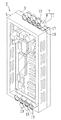
まず、図1は本発明を適用したパチンコ機用基板ケース1を示す斜視図である。本図に示すように、パチンコ機用基板ケース1は、略直方体のケースであり、制御装置を構成する回路基板が固定されたケース本体3に蓋体5を被せることにより、外界から、回路基板を保護している。ケース本体3と蓋体5の固定は、本図において上面および下面に夫々4組ずつ設けられたボス対7によって行なわれる。ボス対7は、蓋体5側に設けられた第1ボス9と、ケース本体3側に設けられた第2ボス11を主要部として構成されている。なお、各第1ボス9には、ボス蓋13が設けられている。
【0056】
図2は、ケース本体3に蓋体5を取り付ける前の状態を示す斜視図である。第2ボス11は、第2連結部15が設けられており、この第2連結部15が第2基台部17を介してケース本体3に固定されている。なお、1つの第2基台部17には第2連結部15を介して4個の第2ボス11が固定されている。
【0057】
一方、第1ボス9にも第1連結部(後述)が設けられており、第1連結部が第1基台部19に固定され、第1基台部19が蓋体5に取り付けられている。
なお、蓋体5の本図手前側の面にはガラス21が嵌め込まれており、回路基板23に対して不正な改造(例えばROM交換)が行なわれた際に、程度の低い改造なら目視で確認できるようにされている。
【0058】
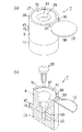
ボス対7の詳細を図3に示す。図3は、1個のボス対7の部分のみを取り出して拡大した斜視図である。なお、本図は、第1ボス9と第2ボス11とがタッピンねじ29にて締結された状態を示しており、第1ボス9が上となるように図1、図2とは向きを変えてある。
【0059】
本図に示すように第1ボス9は、略円柱状の部材であり、円盤状のボス蓋13がその上面31に2本の繋ぎ部33にて連結されている。この繋ぎ部33には、折目35が形成されており、ここで繋ぎ部33を折り曲げるとボス蓋13を上面31に重合させることができる。
【0060】
上面31はその周囲に沿って円環状の包囲部37が設けられている。包囲部37の内径、および上面31からの高さは、ボス蓋13の夫々外径および厚さにほぼ等しくされている。包囲部37の内周面には4個の爪39が突設されている。なお、41はタッピンねじ29の頭を隠すために形成された座繰り、43はタッピンねじ29をねじ込むために第1ボス9に形成されている貫通穴、45は略同様の目的で第2ボス11に形成された螺合穴、47は前述の第1連結部である。
【0061】
一方、第2ボス11は、平たい円柱に第2連結部15を設け、螺合穴45を形成したものとなっている。ボス対7において以上説明した各部(タッピンねじ29は除く)は、何れもABS樹脂を原料として成形されている。
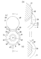
なお、49はボス蓋13を上面31に重合させた際に爪39と係合する切欠である。これについて図4に示す。図4(a)は、第1ボス9の平面図、図4(b)は、ボス蓋13を上面31に重合させる直前の爪39付近を示す拡大斜視図、図4(c)はその重合が為された様子を示す拡大斜視図である。
【0062】
図4(a)に示すように、爪39および切欠49は、夫々包囲部37の内周およびボス蓋13の本図において奥側の縁を周方向に4等分する位置に形成されている。切欠49は、図4(b)に示されているように、ボス蓋13の外周を斜めに切り落とした形態となっている。
【0063】
折目35にて繋ぎ部33を折り曲げていくと、図4(b)に示すように切欠49が爪39に接近し、更に折り曲げるとボス蓋13、爪39が弾性変形してボス蓋13が包囲部37内に嵌まりこみ、図4(c)の状態となる。この状態では、ボス蓋13が上面31に重合されており、爪39は切欠49に係合して、この重合が解けるのを防止する。しかも、ボス蓋13の上面(ハッチングが施された面)、包囲部37の上部、および爪39の上部が面一となる。この面には指先などを引っ掛ける箇所がないため、ボス蓋13を上面31から引き剥がすのは困難である。以下、これら包囲部37、爪39、および切欠49を固定部という。
【0064】
実際に封止を行なう際に行なう作業について図5を用いて説明する。図5(a)はタッピンねじ29にて締結をする直前の状態を、図4(a)のA−Aに相当する位置で断面にした図、図5(b)は当該ボス対7による封止が完了した状態を示す断面図である。なお、実際には本図の右方に、第1基台部19、第2基台部17、ケース本体3、蓋体5等が存在するが、これらは省略している。
【0065】
図5(a)に示すように、締結する前からタッピンねじ29は、貫通穴43から離脱しない程度にねじ込まれている。図5(a)の状態からまず、タッピンねじ29を貫通穴43、螺合穴45にねじ込んでいく。タッピンねじ29の頭部の裏側が座繰り41の中に更に形成されている座繰り51の底面に当接すると締結は完了する。そしてボス蓋13を上面31に重合させ、切欠49を爪39に係合させると、封止は完了し、図5(b)の状態となる。なお、第1ボス9、第2ボス11、ボス蓋13、タッピンねじ29、貫通穴43、螺合穴45、第1連結部47、および第2連結部15が、本発明の基台部固着手段に相当する。
【0066】
この状態では、ボス蓋13を上面31から引き剥がすのが困難であるため、タッピンねじ29を緩めることができない。従って、第1ボス9と第2ボス11との締結を解くことができない。ケース本体3から蓋体5を取り外す必要が生じた場合には、第1連結部47および第2連結部15を切断し、本図の右方にある第1基台部19、第2基台部17からボス対7を離脱させる。
【0067】
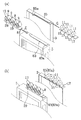
図6に、第1基台部19の蓋体5への取り付け、および第2基台部17のケース本体3への取り付けについて示す。図6(a)は取り付ける前、図6(a)は取り付けた後の状態を示している。なお、本図では、回路基板23は省略されている。
【0068】
図6(a)に示すように蓋体5には、4本の溝53が形成されており、第1基台部19は、その上下面を為す2枚の板を4枚の短冊状の板で繋いだ構造をしている。この短冊状の板が溝53に入り込み、上下面を為す2枚の板が蓋体5の縁を挟むことにより、第1基台部19が蓋体5に取り付けられる。第2基台部17は、第1基台部19と略同様の構造をしており、ケース本体3に形成されている4本の溝55に対して取り付けられる。すなわち、第1基台部19および第2基台部17は、夫々蓋体5およびケース本体3に対して着脱自在にされている。
【0069】
こうして両基台部17、19を取り付け、図6(b)に示すようにケース本体3に、蓋体5を被せ、何れかのタッピンねじ29を用いて締結を行なうと、ケース本体3から蓋体5を取り外せなくなる。そして、同時に図6(a)の状態では着脱自在であった第1基台部19、第2基台部17が、取り外せなくなる。
【0070】
例えば、第1基台部19を蓋体5から取り外すには、蓋体5に対して第1基台部19を矢印Cの方向に移動させるだけで良いが、締結を行なうと、第2ボス11や第2基台部17がこの移動を阻む。第2基台部17についても、第1ボス9や第1基台部19が障害となるので、取り外すことができない。また、この締結が為されたままケース本体3から蓋体5を引き剥がそうとしても、第1ボス9と第2ボス11との締結状態が、これを阻むのでできない。
【0071】
ここで図1に戻る。図1は、パチンコ機用基板ケース1の上下に各4個設けられたボス対7の内、上下各1個を用いて封止を行なった状態を示している。封止は、図5で説明したような簡単な手順で行なうことができ、解封は、第1連結部47および第2連結部15を切断することによって行なう。第1連結部47および第2連結部15は細く成形されたABS樹脂を原料としているため、ニッパ等の刃物で容易に切断することができる。
【0072】
以上のように構成されたパチンコ機用基板ケース1によれば、封止は、タッピンねじ29を閉めるねじ回し以外に工具が不要であり、簡単に行なうことができる。そして、第1連結部47および第2連結部15を切断するだけ、と言う非常に簡単な操作で解封することができる。
【0073】
しかも封止に用いられていないボス蓋13は、ボス対7から起き上がったような形態を取るため、使用中のボスと未使用のボスとが一目で区別できる。図1に示すように、上下で各1個ずつのボス対7を封止に使用すれば、封止が解かれた回数を容易に知ることができる。
【0074】
仮に、すべてのボス対7を使い果たしたら、第1基台部19、第2基台部17を丸ごと新品に交換すればよい。こうすれば、また新たに封止を行なうことも、その封止を解くことも可能となる。また、ボス対7、特に第1ボス9側は、ボス蓋13や第1基台部19を備えていることにより、複雑な形状をしているが、蓋体5と別体にされているので、夫々を別々に製造することができる。従って、両者のコストの上昇を抑えることができる(第2ボス11側も同様)。
【0075】
以上、本発明を適用した実施例として、パチンコ機用基板ケース1について説明してきたが、本発明はこの実施例に何等限定されるものではなく様々な態様で実施しうる。
例えば、前記実施例では、第1ボス9を蓋体5に、第2ボス11をケース本体3に設けたが、タッピンねじ29の締結等に支障がなければ、逆にしてもよい。また、幾つかの第1ボス9は蓋体5に設け、残りの第1ボス9はケース本体3に設ける、という形態でもよい。
【0076】
第1ボス9および第2ボス11を円柱状にしたが、四角柱や断面が楕円の柱など、その他の形状にしてもよい。また、両ボスの形状が異なっていてもよい。例えば、第2ボス11が円柱で、第1ボス9が五角柱でもよい。
つまり、両ボス9、11に対する数および形状の要件は、蓋体5にてケース本体3の蓋をしたときに、貫通穴43と螺合穴45が整合し、タッピンねじ29による締結が可能になっていればよい。
【0077】
このように第1ボス9の形状を変更するならば、これに併せてボス蓋13の形状も変えて構わない。但し、包囲部37の形状は、ボス蓋13の外周の形状や厚さに対応させるのが望ましい。例えば、ボス蓋13の形状を正方形にしたならば、包囲部37の内周側が同じ大きさの正方形となるようにし、高さをボス蓋13の厚さに揃えておく。こうすれば、前記実施例と同様に、ボス蓋13を開放することができず、封止状態を守ることができる。
【0078】
但し、固定部は、包囲部37、爪39、および切欠49以外の態様、例えば図7に示したようなものに変えてもよい。なお、前記実施例と同じ名称の部位については同じ符号を付している。
この態様では図7(a)に示すように、ボス蓋13から切欠49を廃し、代わりに柔軟性のバンド61を設けている。バンド61には鋸歯状の逆止片Kが形成されている。一方、第1ボス9には止め部63を設けている。止め部63はコ字型をしており、挿入口65が形成されている。ボス蓋13を上面31に重合させつつ、バンド61を挿入口65に差し込むと、図7(b)のようになる。このときの止め部63内の様子を図8に示す。
【0079】
図8に示すように、挿入口65内のバンド61の壁面には逆止片Kと係止可能な逆止片Yが設けられている。バンド61を挿入口65に入れると、差込み方向には、バンド61、止め部63の弾性変形により、動かすことが可能であるが、戻り方向には、逆止片K、Yが係止して動かすことができない。
【0080】
従って、この、固定部としてバンド61および止め部63を採用した第1ボス9も、包囲部37、爪39、および切欠49と略同様の効果を奏する。
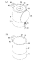
更に、固定部を図9に示したようなもので実現することもできる。この態様では、ボス蓋13に耳片67を設け、更にこの耳片67に突起69を設けている。突起69は、根元部69aは中が詰まっているが、先端部69bは円筒状にされている。一方、第1ボス9にも、ボス蓋13を上面31に重合させた際に耳片67と整合する耳片71が設けられており、これには突起69を挿通させるための穴73が形成されている。
【0081】
ボス蓋13を上面31に重合させ、突起69を穴73に挿通させると、図9(b)のようになる。これだけでは、簡単にボス蓋13を取り外せてしまうので、先端部69bを加熱して潰す。すると図9(c)のようになり、ボス蓋13を取り外すことができなくなる。なお、先端部69bを潰すに際し、先端部69bが中空にされていることにより、小さな力で潰すことができる。このように、固定部として耳片67,71、突起69、および穴73を採用しても、図3や図7に示した態様と同様の効果を奏する。
【0082】
更に、固定部を図10に示したような構成にて実現してもよい。この態様では、図10(a)に示すように、ボス蓋13に突起75を設け、上面31にこの突起75が入りこむ穴79を形成している。突起75の側面には凹凸81が形成されており、穴79に接着剤を入れて、図10(b)のようにボス蓋13を上面31に重合させると、突起75を穴79にしっかりと固着することができる。このように、固定部として突起75および穴79を採用しても、図3、図7、および図9に示した態様と略同様の効果を奏する。
【0083】
第1基台部19の蓋体5への取付方法も、図6以外の態様を採用してもよい。例えば、図11に示す態様では、第1基台部19を鞘状部材にし、この鞘に入れる刀に相当する部材83を蓋体5に設ける。部材83と蓋体5は部位83aのみによって固定されている。第1基台部19を矢印Eの方向に移動させ、部位83aを穴81に入れて取り付ける。なお部位83aは、第1基台部19の矢印E方向の移動のストッパーを兼ねている。第2基台部17のケース本体3への取り付けも同様にして行なうが、部材85を第2基台部17の穴(図示しない)に差し込む際の移動方向Gが矢印Eとは逆になっている。
【0084】
両基台部17、19の取り付けが完了した様子が図11(b)である。この状態からケース本体3に蓋体5を被せ、タッピンねじ29にて締結を行なうと、図6に示した態様と同様、第1基台部19、第2基台部17は何れも取り外しができなくなる。例えば、第1基台部19を蓋体5から取り外すには、矢印Eとは逆方向に移動させればよいのだが、第1基台部19に対し、ボス対等を介して締結されている第2基台部17が、部位85aに当接してこの移動を阻むので、取り外すことができない。逆に、第2基台部17をケース本体3から取り外そうとしても、第1基台部19、部位83a等が矢印Gと逆方向の移動を阻むため、やはり取り外すことができない。
【0085】
従って、図11に示した第1基台部19、第2基台部17の取付方法は、図6に示した態様と略同様の効果を奏することができる。
また、図12に示すように、第1基台部19を大型化して、タッピンねじ29を収納する箱91を設けてもよい。本図では第1ボス9にタッピンねじ29をねじ込んでいるが、箱91を設け、この中にタッピンねじ29を入れておくことにより、第1ボス9にタッピンねじ29をねじ込む工程が不要となる。すなわち、前記実施例では、解封を行なうか否かに関わらず、全ての貫通穴43にタッピンねじ29をねじ込んでおく必要があったが、この態様では、出荷時の封止に用いる数だけねじ込み、封止しておけばよい。なお、貫通穴43にタッピンねじ29をねじ込んでおく態様においても、箱91を設けておけば、ここに予備のタッピンねじ29を入れておくことができる。
【0086】
また、タッピンねじ29に代えて、図14に示したねじ120を用いてもよい。こうすれば、ボス蓋13とねじ120とにより、2重に封止状態を守ることができるため、第1連結部47および第2連結部15を切断することなく解封することが一層困難となる。
【0087】
このように2重に封止状態を守るには、ねじ120以外の態様でもよい。緩めてボス対7の締結を解くことができないようにする態様であれば、その他の形態を採用することができる。
また、第1ボス9や第2連結部15の原料としてABS樹脂を用いたが、封止の際の切断や成形等に支障がなければ、ポリカーボネート、塩化ビニル等の合成樹脂や、合成樹脂以外の材料を用いても構わない。
【図面の簡単な説明】
【図1】本発明を適用したパチンコ機用基板ケース1の斜視図である。
【図2】パチンコ機用基板ケース1のケース本体3に蓋体5を取り付ける前の状態を示す斜視図である。
【図3】第1ボス9および第2ボス11の詳細を示す説明図である。
【図4】ボス蓋13による封止を説明するための拡大図である。
【図5】封止の仕方を説明するための断面図である。
【図6】第1基台部19の蓋体5への取り付け方等を示す説明図である。
【図7】固定部の第2の態様を示す説明図である。
【図8】バンド61と止め部63による封止の仕組みを示す説明図である。
【図9】固定部の第3の態様を示す説明図である。
【図10】固定部の第4の態様を示す説明図である。
【図11】第1基台部および第2基台部の他の態様を示す説明図である。
【図12】第1基台部19にタッピンねじ29を収納する箱91を設けた様子を示す説明図である。
【図13】従来のパチンコ機用基板ケースの封止構造の説明図である。
【図14】従来のパチンコ機用基板ケースの封止構造に用いられるねじの説明図である。
【符号の説明】
1…パチンコ機用基板ケース 3…ケース本体
5…蓋体 9…第1ボス 11…第2ボス
13…ボス蓋 15…第2連結部
17…第2基台部 19…第1基台部
23…回路基板 29…タッピンねじ
31…上面(一底面) 33…繋ぎ部
37…包囲部 39…爪 41…座繰り
43…貫通穴 45…螺合穴
47…第1連結部 49…切欠[0001]
BACKGROUND OF THE INVENTION
The present invention relates to a sealing structure for a pachinko machine substrate case for housing a control device such as a ROM for a pachinko machine.
[0002]
[Prior art]
Conventionally, a control device such as a ROM for controlling a pachinko machine is provided on the back side of each board. These control devices are housed in a substrate case for a pachinko machine provided on the back side of the board surface.
[0003]
Such a pachinko machine board case is the case where the manufacturer first attaches the control device and puts the lid on it, and if the control device breaks down or is found to be illegal by any means (hereinafter referred to as a special case). Other than), the lid is not opened.
However, if the case body and lid of the pachinko machine board case are sealed after the first control device is installed so that the lid cannot be opened again, a special case occurs and the sealing must be released. In case it interferes.
[0004]
In view of this, there has been proposed a sealing structure in which the lid can be opened relatively easily and, instead, the sealing is known to have been released (hereinafter also referred to as opening). An example of this is shown in FIG. 13A is a view (assumed to be a plan view) viewed from the
[0005]
Further,
[0006]
When a special case (for example, necessity of inspection) occurs, the
When this inspection is completed and sealing is performed for the second time, the
[0007]
That is, it can be seen that the sealing plate 112 has been cut and the sealing has been released, and the number of sealing plates 112 that has been cut can also be found. For example, if a special case has occurred only once, but there are two cut sealing plates 112, it can be seen that someone has illegally opened once.
[0008]
[Problems to be solved by the invention]
However, even in the above-described prior art, there is a possibility that the
[0009]
In addition, the sealing structure as shown in FIG. 13 has a problem that the number of times of unsealing is limited separately from this problem. That is, in the aspect of FIG. 13, it can seal only 4 times. Moreover, since the first one is performed at the time of manufacturing the pachinko machine substrate case, the maximum number of sealing is three. This means that it can be unsealed three times by a regular method, which seems sufficient, but it is desirable that it can be unsealed any number of times in order to cope with an unexpected fraud.
[0014]
The present invention has been made in view of these problems, and the sealing structure of a substrate case for a pachinko machine according to claim 1 (hereinafter also simply referred to as a sealing structure) can cope with any number of times of unsealing. The purpose is to .
[0023]
[Means for Solving the Problems]
In order to solve this problem, the present invention according to claim 1 is provided with a case main body that houses a circuit board for a pachinko machine, and a lid that covers the case main body, the lid and the case In a sealing structure of a substrate case for a pachinko machine that seals the main body with difficulty in separation from each other, a first base portion having a structure in which two plates are connected by a strip-shaped plate, and two plates are strip-shaped plates A second base portion having a structure connected to each other, a groove formed in the lid body and into which a strip-shaped plate of the first base portion enters, a strip of the second base portion formed in the case body And the first base portion and the second base portion sandwich the edge of the lid body and the edge of the case main body with the two plates, respectively. Only when the lid is removable from the case body, the lid and the case, respectively. It is detachable from the main body, in a state where the second base portion and the first base plate portions attached to each said case body and said lid, said second base portion and said first group characterized in that it comprises a base portion secured hand stage for fixing the base portion to each other.
[0049]
DETAILED DESCRIPTION OF THE INVENTION
Sealing structure according to 請 Motomeko 1 is detachably with the first base plate portion provided detachably second base plate portion and the base portion affixed provided to the case main body against the lid By fixing by means, it is fixed indirectly. However, the first base part is detachable only in the state where the lid is removable from the case body (the same applies to the second base part. , Including the removed state).
[0050]
In this way, even if the first base part and / or the second base part needs to be destroyed (usually) in order to unseal, the first base part that has become detachable by this unsealing. If the 1 base part and the 2nd base part are removed and a new 1st base part and a 2nd base part are attached, sealing will become possible again. In this case, when re-sealing is possible using one of the base parts (or a part of the base parts), it may not be removed. Thereafter, it may be replaced with a new base when it becomes unusable due to several unpackings.
[0051]
In addition, since the first base portion and the like can be detached only when the lid body is made removable, the seal cannot be removed by removing the first base portion together. Therefore, the strength of sealing is not threatened.
Therefore, it is possible to cope with any number of times of unsealing.
[0055]
【Example】
Embodiments of the present invention will be described below with reference to the drawings.
FIG. 1 is a perspective view showing a substrate case 1 for a pachinko machine to which the present invention is applied. As shown in the figure, the board case 1 for a pachinko machine is a substantially rectangular parallelepiped case, and a circuit board is formed from the outside by covering the
[0056]
FIG. 2 is a perspective view showing a state before the
[0057]
On the other hand, the
Note that the glass 21 is fitted on the front surface of the
[0058]
Details of the
[0059]
As shown in the figure, the
[0060]
The
[0061]
On the other hand, the 2nd boss |
[0062]
As shown in FIG. 4A, the
[0063]
When the connecting
[0064]
The work performed when actually sealing will be described with reference to FIG. 5A is a cross-sectional view of the state immediately before fastening with the tapping
[0065]
As shown in FIG. 5A, the tapping
[0066]
In this state, it is difficult to peel off the
[0067]
FIG. 6 shows the attachment of the
[0068]
As shown in FIG. 6 (a), the
[0069]
When the
[0070]
For example, in order to remove the
[0071]
Returning now to FIG. FIG. 1 shows a state in which sealing is performed using one each of the upper and lower boss pairs 7 provided on the upper and lower sides of the pachinko machine substrate case 1. The sealing can be performed by a simple procedure as described with reference to FIG. 5, and the unsealing is performed by cutting the first connecting
[0072]
According to the substrate case 1 for a pachinko machine configured as described above, the sealing is easy because it requires no tools other than a screwdriver for closing the tapping
[0073]
Moreover, since the
[0074]
If all the boss pairs 7 are used up, the entire
[0075]
The pachinko machine substrate case 1 has been described above as an embodiment to which the present invention is applied. However, the present invention is not limited to this embodiment, and can be implemented in various modes.
For example, in the above embodiment, the
[0076]
Although the
In other words, the number and shape requirements for both
[0077]
If the shape of the
[0078]
However, you may change a fixing | fixed part into aspects other than the surrounding
In this embodiment, as shown in FIG. 7A, the
[0079]
As shown in FIG. 8, a check piece Y that can be locked to the check piece K is provided on the wall surface of the
[0080]
Therefore, the
Further, the fixing portion can be realized by the one shown in FIG. In this embodiment, an
[0081]
When the
[0082]
Further, the fixing portion may be realized by a configuration as shown in FIG. In this embodiment, as shown in FIG. 10A, a protrusion 75 is provided on the
[0083]
As a method for attaching the
[0084]
FIG. 11B shows a state in which the attachment of both
[0085]
Therefore, the mounting method of the
In addition, as shown in FIG. 12, the
[0086]
Further, instead of the tapping
[0087]
To protect this way the sealing state double root Ji may otherwise than 120. Any other form can be adopted as long as the
Moreover, although ABS resin was used as a raw material of the 1st boss |
[Brief description of the drawings]
FIG. 1 is a perspective view of a substrate case 1 for a pachinko machine to which the present invention is applied.
FIG. 2 is a perspective view showing a state before a
FIG. 3 is an explanatory diagram showing details of a
FIG. 4 is an enlarged view for explaining sealing by a
FIG. 5 is a cross-sectional view for explaining a sealing method.
FIG. 6 is an explanatory diagram showing how to attach the
FIG. 7 is an explanatory diagram showing a second mode of the fixing portion.
FIG. 8 is an explanatory view showing a sealing mechanism by a
FIG. 9 is an explanatory view showing a third mode of the fixing portion.
FIG. 10 is an explanatory view showing a fourth mode of the fixing portion.
FIG. 11 is an explanatory view showing another aspect of the first base portion and the second base portion.
12 is an explanatory view showing a state in which a
FIG. 13 is an explanatory view of a sealing structure of a conventional substrate case for a pachinko machine.
FIG. 14 is an explanatory diagram of screws used in a sealing structure of a conventional substrate case for a pachinko machine.
[Explanation of symbols]
DESCRIPTION OF SYMBOLS 1 ... Substrate case for
Claims (1)
2枚の板を短冊状の板で繋いだ構造の第1基台部と、
2枚の板を短冊状の板で繋いだ構造の第2基台部と、
前記蓋体に形成され、前記第1基台部の短冊状の板が入り込む溝と、
前記ケース本体に形成され、前記第2基台部の短冊状の板が入り込む溝と、
を備え、前記第1基台部および前記第2基台部は、夫々前記蓋体の縁および前記ケース本体の縁を前記2枚の板にて挟むことにより、前記ケース本体から前記蓋体を取り外し自在となった状態でのみ、夫々前記蓋体および前記ケース本体に対して着脱自在にされており、
前記第2基台部および前記第1基台部を夫々前記ケース本体および前記蓋体に取り付けた状態で、該第2基台部および該第1基台部を互いに固着するための基台部固着手段、
を備えることを特徴とするパチンコ機用基板ケースの封止構造。In a sealing structure for a pachinko machine substrate case, comprising a case main body for storing a circuit board for a pachinko machine, and a lid for covering the case main body, and the lid and the case main body are difficult to separate from each other ,
A first base having a structure in which two plates are connected by a strip-shaped plate ;
A second base having a structure in which two plates are connected by a strip-shaped plate ;
A groove formed in the lid and into which a strip-shaped plate of the first base portion enters;
A groove formed in the case main body and into which the strip-shaped plate of the second base portion enters,
The first base portion and the second base portion are configured to sandwich the lid body from the case body by sandwiching an edge of the lid body and an edge of the case body with the two plates, respectively. Only in a state where it can be detached, it is detachable from the lid body and the case body,
A base part for fixing the second base part and the first base part to each other in a state where the second base part and the first base part are attached to the case body and the lid body, respectively. fixed hand stage,
A sealing structure for a substrate case for a pachinko machine, comprising:
Priority Applications (1)
| Application Number | Priority Date | Filing Date | Title |
|---|---|---|---|
| JP2001274917A JP3606245B2 (en) | 2001-09-11 | 2001-09-11 | Sealing structure of substrate case for pachinko machine |
Applications Claiming Priority (1)
| Application Number | Priority Date | Filing Date | Title |
|---|---|---|---|
| JP2001274917A JP3606245B2 (en) | 2001-09-11 | 2001-09-11 | Sealing structure of substrate case for pachinko machine |
Related Parent Applications (1)
| Application Number | Title | Priority Date | Filing Date |
|---|---|---|---|
| JP00988898A Division JP3938999B2 (en) | 1998-01-21 | 1998-01-21 | Sealing structure of substrate case for pachinko machine |
Publications (3)
| Publication Number | Publication Date |
|---|---|
| JP2002126307A JP2002126307A (en) | 2002-05-08 |
| JP3606245B2 true JP3606245B2 (en) | 2005-01-05 |
| JP2002126307A5 JP2002126307A5 (en) | 2005-06-09 |
Family
ID=19099875
Family Applications (1)
| Application Number | Title | Priority Date | Filing Date |
|---|---|---|---|
| JP2001274917A Expired - Fee Related JP3606245B2 (en) | 2001-09-11 | 2001-09-11 | Sealing structure of substrate case for pachinko machine |
Country Status (1)
| Country | Link |
|---|---|
| JP (1) | JP3606245B2 (en) |
Families Citing this family (6)
| Publication number | Priority date | Publication date | Assignee | Title |
|---|---|---|---|---|
| JP2004049428A (en) * | 2002-07-18 | 2004-02-19 | Yamasa Kk | Sealing device for control substrate case of game machine |
| JP4583081B2 (en) * | 2004-06-15 | 2010-11-17 | 株式会社三共 | Game machine |
| JP4657085B2 (en) * | 2005-11-07 | 2011-03-23 | 三菱電機株式会社 | Measuring instrument seal structure |
| JP5099294B2 (en) * | 2006-02-15 | 2012-12-19 | 株式会社三洋物産 | Game machine |
| JP2007313251A (en) * | 2006-05-29 | 2007-12-06 | Aruze Corp | Game machine |
| JP5442371B2 (en) * | 2009-09-18 | 2014-03-12 | 株式会社森創 | Board case for gaming machines |
-
2001
- 2001-09-11 JP JP2001274917A patent/JP3606245B2/en not_active Expired - Fee Related
Also Published As
| Publication number | Publication date |
|---|---|
| JP2002126307A (en) | 2002-05-08 |
Similar Documents
| Publication | Publication Date | Title |
|---|---|---|
| JP3937048B2 (en) | Control board storage box for pachinko machines | |
| US20080236859A1 (en) | Protective device plate for an electrical box | |
| JP3606245B2 (en) | Sealing structure of substrate case for pachinko machine | |
| JP4374506B2 (en) | PCB storage box | |
| JP4292304B2 (en) | Control board storage box fraud prevention structure | |
| JP3938999B2 (en) | Sealing structure of substrate case for pachinko machine | |
| JP2000079243A (en) | Controller of game machine | |
| WO2007058496A1 (en) | Closure of vessel and process for manufacturing same | |
| JP4075098B2 (en) | Control board storage box for gaming machines | |
| JP2002126307A5 (en) | ||
| JP4756507B2 (en) | Control board storage box for gaming machines | |
| JP4235977B2 (en) | Control board storage box for pachinko machines | |
| JP3729221B2 (en) | Seal structure | |
| JP4756508B2 (en) | Control board storage box for gaming machines | |
| JP4756509B2 (en) | Control board storage box for gaming machines | |
| JP2000079244A (en) | Control board housing box for game machine | |
| JP5573207B2 (en) | Control board case for gaming machines | |
| JP3714976B2 (en) | Waterproof plate and waterproof switch | |
| CN220045967U (en) | Nail head assembly and surgical anastomat | |
| JP6186024B2 (en) | Instrument mounting member | |
| JP4158899B2 (en) | Equipment mounting panel | |
| JP4218070B2 (en) | Sealing structure of substrate storage box in pachinko machine | |
| JP2004150476A (en) | Fixing tool and plate member fixing method using the same | |
| JP3832391B2 (en) | Wiring plate | |
| KR200265009Y1 (en) | An attaching device of an auxiliary lock mounted on a fire prevention door |
Legal Events
| Date | Code | Title | Description |
|---|---|---|---|
| A521 | Written amendment |
Free format text: JAPANESE INTERMEDIATE CODE: A523 Effective date: 20040826 |
|
| TRDD | Decision of grant or rejection written | ||
| A01 | Written decision to grant a patent or to grant a registration (utility model) |
Free format text: JAPANESE INTERMEDIATE CODE: A01 Effective date: 20040914 |
|
| A61 | First payment of annual fees (during grant procedure) |
Free format text: JAPANESE INTERMEDIATE CODE: A61 Effective date: 20040927 |
|
| R150 | Certificate of patent or registration of utility model |
Free format text: JAPANESE INTERMEDIATE CODE: R150 |
|
| S531 | Written request for registration of change of domicile |
Free format text: JAPANESE INTERMEDIATE CODE: R313531 |
|
| R350 | Written notification of registration of transfer |
Free format text: JAPANESE INTERMEDIATE CODE: R350 |
|
| FPAY | Renewal fee payment (event date is renewal date of database) |
Free format text: PAYMENT UNTIL: 20081015 Year of fee payment: 4 |
|
| FPAY | Renewal fee payment (event date is renewal date of database) |
Free format text: PAYMENT UNTIL: 20091015 Year of fee payment: 5 |
|
| FPAY | Renewal fee payment (event date is renewal date of database) |
Free format text: PAYMENT UNTIL: 20091015 Year of fee payment: 5 |
|
| FPAY | Renewal fee payment (event date is renewal date of database) |
Free format text: PAYMENT UNTIL: 20101015 Year of fee payment: 6 |
|
| FPAY | Renewal fee payment (event date is renewal date of database) |
Free format text: PAYMENT UNTIL: 20101015 Year of fee payment: 6 |
|
| FPAY | Renewal fee payment (event date is renewal date of database) |
Free format text: PAYMENT UNTIL: 20111015 Year of fee payment: 7 |
|
| LAPS | Cancellation because of no payment of annual fees |