JP3602130B2 - Natural gas liquefaction method and apparatus - Google Patents
Natural gas liquefaction method and apparatus Download PDFInfo
- Publication number
- JP3602130B2 JP3602130B2 JP51781795A JP51781795A JP3602130B2 JP 3602130 B2 JP3602130 B2 JP 3602130B2 JP 51781795 A JP51781795 A JP 51781795A JP 51781795 A JP51781795 A JP 51781795A JP 3602130 B2 JP3602130 B2 JP 3602130B2
- Authority
- JP
- Japan
- Prior art keywords
- natural gas
- fraction
- gas
- liquid
- expansion
- Prior art date
- Legal status (The legal status is an assumption and is not a legal conclusion. Google has not performed a legal analysis and makes no representation as to the accuracy of the status listed.)
- Expired - Lifetime
Links
- VNWKTOKETHGBQD-UHFFFAOYSA-N methane Chemical compound C VNWKTOKETHGBQD-UHFFFAOYSA-N 0.000 title claims abstract description 330
- 239000003345 natural gas Substances 0.000 title claims abstract description 143
- 238000000034 method Methods 0.000 title claims abstract description 99
- 239000007789 gas Substances 0.000 claims abstract description 100
- 239000012071 phase Substances 0.000 claims abstract description 93
- 239000007791 liquid phase Substances 0.000 claims abstract description 37
- IJGRMHOSHXDMSA-UHFFFAOYSA-N Atomic nitrogen Chemical compound N#N IJGRMHOSHXDMSA-UHFFFAOYSA-N 0.000 claims description 83
- 239000000203 mixture Substances 0.000 claims description 58
- 239000007788 liquid Substances 0.000 claims description 54
- 238000001816 cooling Methods 0.000 claims description 46
- 230000008569 process Effects 0.000 claims description 45
- 229910052757 nitrogen Inorganic materials 0.000 claims description 41
- 238000007906 compression Methods 0.000 claims description 23
- 230000006835 compression Effects 0.000 claims description 21
- 229930195733 hydrocarbon Natural products 0.000 claims description 20
- 150000002430 hydrocarbons Chemical class 0.000 claims description 20
- 239000003949 liquefied natural gas Substances 0.000 claims description 18
- 239000003507 refrigerant Substances 0.000 claims description 13
- 239000012808 vapor phase Substances 0.000 claims description 6
- 238000001704 evaporation Methods 0.000 claims description 5
- 238000006243 chemical reaction Methods 0.000 claims description 4
- 238000000926 separation method Methods 0.000 claims description 4
- 239000000463 material Substances 0.000 claims description 3
- 238000004064 recycling Methods 0.000 claims description 3
- 229920002994 synthetic fiber Polymers 0.000 claims description 3
- 238000007599 discharging Methods 0.000 claims 1
- 230000007704 transition Effects 0.000 abstract description 18
- 239000002609 medium Substances 0.000 description 8
- XLYOFNOQVPJJNP-UHFFFAOYSA-N water Substances O XLYOFNOQVPJJNP-UHFFFAOYSA-N 0.000 description 8
- 238000010586 diagram Methods 0.000 description 5
- 238000001179 sorption measurement Methods 0.000 description 5
- 238000003795 desorption Methods 0.000 description 4
- FNYLWPVRPXGIIP-UHFFFAOYSA-N Triamterene Chemical compound NC1=NC2=NC(N)=NC(N)=C2N=C1C1=CC=CC=C1 FNYLWPVRPXGIIP-UHFFFAOYSA-N 0.000 description 3
- 230000008859 change Effects 0.000 description 3
- 239000002826 coolant Substances 0.000 description 3
- 239000012809 cooling fluid Substances 0.000 description 3
- 239000000110 cooling liquid Substances 0.000 description 3
- 230000008020 evaporation Effects 0.000 description 3
- 239000012530 fluid Substances 0.000 description 3
- 239000011555 saturated liquid Substances 0.000 description 3
- OKTJSMMVPCPJKN-UHFFFAOYSA-N Carbon Chemical compound [C] OKTJSMMVPCPJKN-UHFFFAOYSA-N 0.000 description 2
- 239000003463 adsorbent Substances 0.000 description 2
- 229910001873 dinitrogen Inorganic materials 0.000 description 2
- 238000004821 distillation Methods 0.000 description 2
- 238000012986 modification Methods 0.000 description 2
- 230000004048 modification Effects 0.000 description 2
- 238000002360 preparation method Methods 0.000 description 2
- 230000000630 rising effect Effects 0.000 description 2
- FGUUSXIOTUKUDN-IBGZPJMESA-N C1(=CC=CC=C1)N1C2=C(NC([C@H](C1)NC=1OC(=NN=1)C1=CC=CC=C1)=O)C=CC=C2 Chemical compound C1(=CC=CC=C1)N1C2=C(NC([C@H](C1)NC=1OC(=NN=1)C1=CC=CC=C1)=O)C=CC=C2 FGUUSXIOTUKUDN-IBGZPJMESA-N 0.000 description 1
- 229910021536 Zeolite Inorganic materials 0.000 description 1
- 238000009825 accumulation Methods 0.000 description 1
- 238000007792 addition Methods 0.000 description 1
- 229910052782 aluminium Inorganic materials 0.000 description 1
- XAGFODPZIPBFFR-UHFFFAOYSA-N aluminium Chemical compound [Al] XAGFODPZIPBFFR-UHFFFAOYSA-N 0.000 description 1
- PNEYBMLMFCGWSK-UHFFFAOYSA-N aluminium oxide Inorganic materials [O-2].[O-2].[O-2].[Al+3].[Al+3] PNEYBMLMFCGWSK-UHFFFAOYSA-N 0.000 description 1
- 238000009835 boiling Methods 0.000 description 1
- 239000002131 composite material Substances 0.000 description 1
- 238000009833 condensation Methods 0.000 description 1
- 230000005494 condensation Effects 0.000 description 1
- 239000004020 conductor Substances 0.000 description 1
- 239000000112 cooling gas Substances 0.000 description 1
- 238000002425 crystallisation Methods 0.000 description 1
- 230000008025 crystallization Effects 0.000 description 1
- HNPSIPDUKPIQMN-UHFFFAOYSA-N dioxosilane;oxo(oxoalumanyloxy)alumane Chemical compound O=[Si]=O.O=[Al]O[Al]=O HNPSIPDUKPIQMN-UHFFFAOYSA-N 0.000 description 1
- 239000000446 fuel Substances 0.000 description 1
- 239000008246 gaseous mixture Substances 0.000 description 1
- 238000004519 manufacturing process Methods 0.000 description 1
- 229910052751 metal Inorganic materials 0.000 description 1
- 239000002184 metal Substances 0.000 description 1
- 150000002829 nitrogen Chemical class 0.000 description 1
- QJGQUHMNIGDVPM-UHFFFAOYSA-N nitrogen group Chemical group [N] QJGQUHMNIGDVPM-UHFFFAOYSA-N 0.000 description 1
- 238000007781 pre-processing Methods 0.000 description 1
- 239000007320 rich medium Substances 0.000 description 1
- 239000002904 solvent Substances 0.000 description 1
- 229910001220 stainless steel Inorganic materials 0.000 description 1
- 239000010935 stainless steel Substances 0.000 description 1
- 239000000126 substance Substances 0.000 description 1
- 238000011144 upstream manufacturing Methods 0.000 description 1
- 239000010457 zeolite Substances 0.000 description 1
Images


Classifications
-
- F—MECHANICAL ENGINEERING; LIGHTING; HEATING; WEAPONS; BLASTING
- F25—REFRIGERATION OR COOLING; COMBINED HEATING AND REFRIGERATION SYSTEMS; HEAT PUMP SYSTEMS; MANUFACTURE OR STORAGE OF ICE; LIQUEFACTION SOLIDIFICATION OF GASES
- F25J—LIQUEFACTION, SOLIDIFICATION OR SEPARATION OF GASES OR GASEOUS OR LIQUEFIED GASEOUS MIXTURES BY PRESSURE AND COLD TREATMENT OR BY BRINGING THEM INTO THE SUPERCRITICAL STATE
- F25J3/00—Processes or apparatus for separating the constituents of gaseous or liquefied gaseous mixtures involving the use of liquefaction or solidification
- F25J3/06—Processes or apparatus for separating the constituents of gaseous or liquefied gaseous mixtures involving the use of liquefaction or solidification by partial condensation
-
- F—MECHANICAL ENGINEERING; LIGHTING; HEATING; WEAPONS; BLASTING
- F25—REFRIGERATION OR COOLING; COMBINED HEATING AND REFRIGERATION SYSTEMS; HEAT PUMP SYSTEMS; MANUFACTURE OR STORAGE OF ICE; LIQUEFACTION SOLIDIFICATION OF GASES
- F25J—LIQUEFACTION, SOLIDIFICATION OR SEPARATION OF GASES OR GASEOUS OR LIQUEFIED GASEOUS MIXTURES BY PRESSURE AND COLD TREATMENT OR BY BRINGING THEM INTO THE SUPERCRITICAL STATE
- F25J3/00—Processes or apparatus for separating the constituents of gaseous or liquefied gaseous mixtures involving the use of liquefaction or solidification
- F25J3/02—Processes or apparatus for separating the constituents of gaseous or liquefied gaseous mixtures involving the use of liquefaction or solidification by rectification, i.e. by continuous interchange of heat and material between a vapour stream and a liquid stream
- F25J3/0228—Processes or apparatus for separating the constituents of gaseous or liquefied gaseous mixtures involving the use of liquefaction or solidification by rectification, i.e. by continuous interchange of heat and material between a vapour stream and a liquid stream characterised by the separated product stream
- F25J3/0257—Processes or apparatus for separating the constituents of gaseous or liquefied gaseous mixtures involving the use of liquefaction or solidification by rectification, i.e. by continuous interchange of heat and material between a vapour stream and a liquid stream characterised by the separated product stream separation of nitrogen
-
- F—MECHANICAL ENGINEERING; LIGHTING; HEATING; WEAPONS; BLASTING
- F25—REFRIGERATION OR COOLING; COMBINED HEATING AND REFRIGERATION SYSTEMS; HEAT PUMP SYSTEMS; MANUFACTURE OR STORAGE OF ICE; LIQUEFACTION SOLIDIFICATION OF GASES
- F25J—LIQUEFACTION, SOLIDIFICATION OR SEPARATION OF GASES OR GASEOUS OR LIQUEFIED GASEOUS MIXTURES BY PRESSURE AND COLD TREATMENT OR BY BRINGING THEM INTO THE SUPERCRITICAL STATE
- F25J1/00—Processes or apparatus for liquefying or solidifying gases or gaseous mixtures
- F25J1/0002—Processes or apparatus for liquefying or solidifying gases or gaseous mixtures characterised by the fluid to be liquefied
- F25J1/0022—Hydrocarbons, e.g. natural gas
-
- F—MECHANICAL ENGINEERING; LIGHTING; HEATING; WEAPONS; BLASTING
- F25—REFRIGERATION OR COOLING; COMBINED HEATING AND REFRIGERATION SYSTEMS; HEAT PUMP SYSTEMS; MANUFACTURE OR STORAGE OF ICE; LIQUEFACTION SOLIDIFICATION OF GASES
- F25J—LIQUEFACTION, SOLIDIFICATION OR SEPARATION OF GASES OR GASEOUS OR LIQUEFIED GASEOUS MIXTURES BY PRESSURE AND COLD TREATMENT OR BY BRINGING THEM INTO THE SUPERCRITICAL STATE
- F25J1/00—Processes or apparatus for liquefying or solidifying gases or gaseous mixtures
- F25J1/003—Processes or apparatus for liquefying or solidifying gases or gaseous mixtures characterised by the kind of cold generation within the liquefaction unit for compensating heat leaks and liquid production
- F25J1/0032—Processes or apparatus for liquefying or solidifying gases or gaseous mixtures characterised by the kind of cold generation within the liquefaction unit for compensating heat leaks and liquid production using the feed stream itself or separated fractions from it, i.e. "internal refrigeration"
- F25J1/0035—Processes or apparatus for liquefying or solidifying gases or gaseous mixtures characterised by the kind of cold generation within the liquefaction unit for compensating heat leaks and liquid production using the feed stream itself or separated fractions from it, i.e. "internal refrigeration" by gas expansion with extraction of work
- F25J1/0037—Processes or apparatus for liquefying or solidifying gases or gaseous mixtures characterised by the kind of cold generation within the liquefaction unit for compensating heat leaks and liquid production using the feed stream itself or separated fractions from it, i.e. "internal refrigeration" by gas expansion with extraction of work of a return stream
-
- F—MECHANICAL ENGINEERING; LIGHTING; HEATING; WEAPONS; BLASTING
- F25—REFRIGERATION OR COOLING; COMBINED HEATING AND REFRIGERATION SYSTEMS; HEAT PUMP SYSTEMS; MANUFACTURE OR STORAGE OF ICE; LIQUEFACTION SOLIDIFICATION OF GASES
- F25J—LIQUEFACTION, SOLIDIFICATION OR SEPARATION OF GASES OR GASEOUS OR LIQUEFIED GASEOUS MIXTURES BY PRESSURE AND COLD TREATMENT OR BY BRINGING THEM INTO THE SUPERCRITICAL STATE
- F25J1/00—Processes or apparatus for liquefying or solidifying gases or gaseous mixtures
- F25J1/003—Processes or apparatus for liquefying or solidifying gases or gaseous mixtures characterised by the kind of cold generation within the liquefaction unit for compensating heat leaks and liquid production
- F25J1/0032—Processes or apparatus for liquefying or solidifying gases or gaseous mixtures characterised by the kind of cold generation within the liquefaction unit for compensating heat leaks and liquid production using the feed stream itself or separated fractions from it, i.e. "internal refrigeration"
- F25J1/004—Processes or apparatus for liquefying or solidifying gases or gaseous mixtures characterised by the kind of cold generation within the liquefaction unit for compensating heat leaks and liquid production using the feed stream itself or separated fractions from it, i.e. "internal refrigeration" by flash gas recovery
-
- F—MECHANICAL ENGINEERING; LIGHTING; HEATING; WEAPONS; BLASTING
- F25—REFRIGERATION OR COOLING; COMBINED HEATING AND REFRIGERATION SYSTEMS; HEAT PUMP SYSTEMS; MANUFACTURE OR STORAGE OF ICE; LIQUEFACTION SOLIDIFICATION OF GASES
- F25J—LIQUEFACTION, SOLIDIFICATION OR SEPARATION OF GASES OR GASEOUS OR LIQUEFIED GASEOUS MIXTURES BY PRESSURE AND COLD TREATMENT OR BY BRINGING THEM INTO THE SUPERCRITICAL STATE
- F25J1/00—Processes or apparatus for liquefying or solidifying gases or gaseous mixtures
- F25J1/003—Processes or apparatus for liquefying or solidifying gases or gaseous mixtures characterised by the kind of cold generation within the liquefaction unit for compensating heat leaks and liquid production
- F25J1/0032—Processes or apparatus for liquefying or solidifying gases or gaseous mixtures characterised by the kind of cold generation within the liquefaction unit for compensating heat leaks and liquid production using the feed stream itself or separated fractions from it, i.e. "internal refrigeration"
- F25J1/0042—Processes or apparatus for liquefying or solidifying gases or gaseous mixtures characterised by the kind of cold generation within the liquefaction unit for compensating heat leaks and liquid production using the feed stream itself or separated fractions from it, i.e. "internal refrigeration" by liquid expansion with extraction of work
-
- F—MECHANICAL ENGINEERING; LIGHTING; HEATING; WEAPONS; BLASTING
- F25—REFRIGERATION OR COOLING; COMBINED HEATING AND REFRIGERATION SYSTEMS; HEAT PUMP SYSTEMS; MANUFACTURE OR STORAGE OF ICE; LIQUEFACTION SOLIDIFICATION OF GASES
- F25J—LIQUEFACTION, SOLIDIFICATION OR SEPARATION OF GASES OR GASEOUS OR LIQUEFIED GASEOUS MIXTURES BY PRESSURE AND COLD TREATMENT OR BY BRINGING THEM INTO THE SUPERCRITICAL STATE
- F25J1/00—Processes or apparatus for liquefying or solidifying gases or gaseous mixtures
- F25J1/003—Processes or apparatus for liquefying or solidifying gases or gaseous mixtures characterised by the kind of cold generation within the liquefaction unit for compensating heat leaks and liquid production
- F25J1/0047—Processes or apparatus for liquefying or solidifying gases or gaseous mixtures characterised by the kind of cold generation within the liquefaction unit for compensating heat leaks and liquid production using an "external" refrigerant stream in a closed vapor compression cycle
- F25J1/0052—Processes or apparatus for liquefying or solidifying gases or gaseous mixtures characterised by the kind of cold generation within the liquefaction unit for compensating heat leaks and liquid production using an "external" refrigerant stream in a closed vapor compression cycle by vaporising a liquid refrigerant stream
-
- F—MECHANICAL ENGINEERING; LIGHTING; HEATING; WEAPONS; BLASTING
- F25—REFRIGERATION OR COOLING; COMBINED HEATING AND REFRIGERATION SYSTEMS; HEAT PUMP SYSTEMS; MANUFACTURE OR STORAGE OF ICE; LIQUEFACTION SOLIDIFICATION OF GASES
- F25J—LIQUEFACTION, SOLIDIFICATION OR SEPARATION OF GASES OR GASEOUS OR LIQUEFIED GASEOUS MIXTURES BY PRESSURE AND COLD TREATMENT OR BY BRINGING THEM INTO THE SUPERCRITICAL STATE
- F25J1/00—Processes or apparatus for liquefying or solidifying gases or gaseous mixtures
- F25J1/02—Processes or apparatus for liquefying or solidifying gases or gaseous mixtures requiring the use of refrigeration, e.g. of helium or hydrogen ; Details and kind of the refrigeration system used; Integration with other units or processes; Controlling aspects of the process
- F25J1/0201—Processes or apparatus for liquefying or solidifying gases or gaseous mixtures requiring the use of refrigeration, e.g. of helium or hydrogen ; Details and kind of the refrigeration system used; Integration with other units or processes; Controlling aspects of the process using only internal refrigeration means, i.e. without external refrigeration
- F25J1/0202—Processes or apparatus for liquefying or solidifying gases or gaseous mixtures requiring the use of refrigeration, e.g. of helium or hydrogen ; Details and kind of the refrigeration system used; Integration with other units or processes; Controlling aspects of the process using only internal refrigeration means, i.e. without external refrigeration in a quasi-closed internal refrigeration loop
-
- F—MECHANICAL ENGINEERING; LIGHTING; HEATING; WEAPONS; BLASTING
- F25—REFRIGERATION OR COOLING; COMBINED HEATING AND REFRIGERATION SYSTEMS; HEAT PUMP SYSTEMS; MANUFACTURE OR STORAGE OF ICE; LIQUEFACTION SOLIDIFICATION OF GASES
- F25J—LIQUEFACTION, SOLIDIFICATION OR SEPARATION OF GASES OR GASEOUS OR LIQUEFIED GASEOUS MIXTURES BY PRESSURE AND COLD TREATMENT OR BY BRINGING THEM INTO THE SUPERCRITICAL STATE
- F25J1/00—Processes or apparatus for liquefying or solidifying gases or gaseous mixtures
- F25J1/02—Processes or apparatus for liquefying or solidifying gases or gaseous mixtures requiring the use of refrigeration, e.g. of helium or hydrogen ; Details and kind of the refrigeration system used; Integration with other units or processes; Controlling aspects of the process
- F25J1/0211—Processes or apparatus for liquefying or solidifying gases or gaseous mixtures requiring the use of refrigeration, e.g. of helium or hydrogen ; Details and kind of the refrigeration system used; Integration with other units or processes; Controlling aspects of the process using a multi-component refrigerant [MCR] fluid in a closed vapor compression cycle
- F25J1/0219—Processes or apparatus for liquefying or solidifying gases or gaseous mixtures requiring the use of refrigeration, e.g. of helium or hydrogen ; Details and kind of the refrigeration system used; Integration with other units or processes; Controlling aspects of the process using a multi-component refrigerant [MCR] fluid in a closed vapor compression cycle in combination with an internal quasi-closed refrigeration loop, e.g. using a deep flash recycle loop
-
- F—MECHANICAL ENGINEERING; LIGHTING; HEATING; WEAPONS; BLASTING
- F25—REFRIGERATION OR COOLING; COMBINED HEATING AND REFRIGERATION SYSTEMS; HEAT PUMP SYSTEMS; MANUFACTURE OR STORAGE OF ICE; LIQUEFACTION SOLIDIFICATION OF GASES
- F25J—LIQUEFACTION, SOLIDIFICATION OR SEPARATION OF GASES OR GASEOUS OR LIQUEFIED GASEOUS MIXTURES BY PRESSURE AND COLD TREATMENT OR BY BRINGING THEM INTO THE SUPERCRITICAL STATE
- F25J1/00—Processes or apparatus for liquefying or solidifying gases or gaseous mixtures
- F25J1/02—Processes or apparatus for liquefying or solidifying gases or gaseous mixtures requiring the use of refrigeration, e.g. of helium or hydrogen ; Details and kind of the refrigeration system used; Integration with other units or processes; Controlling aspects of the process
- F25J1/0243—Start-up or control of the process; Details of the apparatus used; Details of the refrigerant compression system used
- F25J1/0244—Operation; Control and regulation; Instrumentation
- F25J1/0254—Operation; Control and regulation; Instrumentation controlling particular process parameter, e.g. pressure, temperature
-
- F—MECHANICAL ENGINEERING; LIGHTING; HEATING; WEAPONS; BLASTING
- F25—REFRIGERATION OR COOLING; COMBINED HEATING AND REFRIGERATION SYSTEMS; HEAT PUMP SYSTEMS; MANUFACTURE OR STORAGE OF ICE; LIQUEFACTION SOLIDIFICATION OF GASES
- F25J—LIQUEFACTION, SOLIDIFICATION OR SEPARATION OF GASES OR GASEOUS OR LIQUEFIED GASEOUS MIXTURES BY PRESSURE AND COLD TREATMENT OR BY BRINGING THEM INTO THE SUPERCRITICAL STATE
- F25J1/00—Processes or apparatus for liquefying or solidifying gases or gaseous mixtures
- F25J1/02—Processes or apparatus for liquefying or solidifying gases or gaseous mixtures requiring the use of refrigeration, e.g. of helium or hydrogen ; Details and kind of the refrigeration system used; Integration with other units or processes; Controlling aspects of the process
- F25J1/0243—Start-up or control of the process; Details of the apparatus used; Details of the refrigerant compression system used
- F25J1/0257—Construction and layout of liquefaction equipments, e.g. valves, machines
- F25J1/0262—Details of the cold heat exchange system
- F25J1/0264—Arrangement of heat exchanger cores in parallel with different functions, e.g. different cooling streams
-
- F—MECHANICAL ENGINEERING; LIGHTING; HEATING; WEAPONS; BLASTING
- F25—REFRIGERATION OR COOLING; COMBINED HEATING AND REFRIGERATION SYSTEMS; HEAT PUMP SYSTEMS; MANUFACTURE OR STORAGE OF ICE; LIQUEFACTION SOLIDIFICATION OF GASES
- F25J—LIQUEFACTION, SOLIDIFICATION OR SEPARATION OF GASES OR GASEOUS OR LIQUEFIED GASEOUS MIXTURES BY PRESSURE AND COLD TREATMENT OR BY BRINGING THEM INTO THE SUPERCRITICAL STATE
- F25J1/00—Processes or apparatus for liquefying or solidifying gases or gaseous mixtures
- F25J1/02—Processes or apparatus for liquefying or solidifying gases or gaseous mixtures requiring the use of refrigeration, e.g. of helium or hydrogen ; Details and kind of the refrigeration system used; Integration with other units or processes; Controlling aspects of the process
- F25J1/0243—Start-up or control of the process; Details of the apparatus used; Details of the refrigerant compression system used
- F25J1/0279—Compression of refrigerant or internal recycle fluid, e.g. kind of compressor, accumulator, suction drum etc.
- F25J1/0281—Compression of refrigerant or internal recycle fluid, e.g. kind of compressor, accumulator, suction drum etc. characterised by the type of prime driver, e.g. hot gas expander
- F25J1/0282—Steam turbine as the prime mechanical driver
-
- F—MECHANICAL ENGINEERING; LIGHTING; HEATING; WEAPONS; BLASTING
- F25—REFRIGERATION OR COOLING; COMBINED HEATING AND REFRIGERATION SYSTEMS; HEAT PUMP SYSTEMS; MANUFACTURE OR STORAGE OF ICE; LIQUEFACTION SOLIDIFICATION OF GASES
- F25J—LIQUEFACTION, SOLIDIFICATION OR SEPARATION OF GASES OR GASEOUS OR LIQUEFIED GASEOUS MIXTURES BY PRESSURE AND COLD TREATMENT OR BY BRINGING THEM INTO THE SUPERCRITICAL STATE
- F25J1/00—Processes or apparatus for liquefying or solidifying gases or gaseous mixtures
- F25J1/02—Processes or apparatus for liquefying or solidifying gases or gaseous mixtures requiring the use of refrigeration, e.g. of helium or hydrogen ; Details and kind of the refrigeration system used; Integration with other units or processes; Controlling aspects of the process
- F25J1/0243—Start-up or control of the process; Details of the apparatus used; Details of the refrigerant compression system used
- F25J1/0279—Compression of refrigerant or internal recycle fluid, e.g. kind of compressor, accumulator, suction drum etc.
- F25J1/0281—Compression of refrigerant or internal recycle fluid, e.g. kind of compressor, accumulator, suction drum etc. characterised by the type of prime driver, e.g. hot gas expander
- F25J1/0283—Gas turbine as the prime mechanical driver
-
- F—MECHANICAL ENGINEERING; LIGHTING; HEATING; WEAPONS; BLASTING
- F25—REFRIGERATION OR COOLING; COMBINED HEATING AND REFRIGERATION SYSTEMS; HEAT PUMP SYSTEMS; MANUFACTURE OR STORAGE OF ICE; LIQUEFACTION SOLIDIFICATION OF GASES
- F25J—LIQUEFACTION, SOLIDIFICATION OR SEPARATION OF GASES OR GASEOUS OR LIQUEFIED GASEOUS MIXTURES BY PRESSURE AND COLD TREATMENT OR BY BRINGING THEM INTO THE SUPERCRITICAL STATE
- F25J1/00—Processes or apparatus for liquefying or solidifying gases or gaseous mixtures
- F25J1/02—Processes or apparatus for liquefying or solidifying gases or gaseous mixtures requiring the use of refrigeration, e.g. of helium or hydrogen ; Details and kind of the refrigeration system used; Integration with other units or processes; Controlling aspects of the process
- F25J1/0243—Start-up or control of the process; Details of the apparatus used; Details of the refrigerant compression system used
- F25J1/0279—Compression of refrigerant or internal recycle fluid, e.g. kind of compressor, accumulator, suction drum etc.
- F25J1/0285—Combination of different types of drivers mechanically coupled to the same refrigerant compressor, possibly split on multiple compressor casings
- F25J1/0288—Combination of different types of drivers mechanically coupled to the same refrigerant compressor, possibly split on multiple compressor casings using work extraction by mechanical coupling of compression and expansion of the refrigerant, so-called companders
-
- F—MECHANICAL ENGINEERING; LIGHTING; HEATING; WEAPONS; BLASTING
- F25—REFRIGERATION OR COOLING; COMBINED HEATING AND REFRIGERATION SYSTEMS; HEAT PUMP SYSTEMS; MANUFACTURE OR STORAGE OF ICE; LIQUEFACTION SOLIDIFICATION OF GASES
- F25J—LIQUEFACTION, SOLIDIFICATION OR SEPARATION OF GASES OR GASEOUS OR LIQUEFIED GASEOUS MIXTURES BY PRESSURE AND COLD TREATMENT OR BY BRINGING THEM INTO THE SUPERCRITICAL STATE
- F25J3/00—Processes or apparatus for separating the constituents of gaseous or liquefied gaseous mixtures involving the use of liquefaction or solidification
- F25J3/02—Processes or apparatus for separating the constituents of gaseous or liquefied gaseous mixtures involving the use of liquefaction or solidification by rectification, i.e. by continuous interchange of heat and material between a vapour stream and a liquid stream
- F25J3/0204—Processes or apparatus for separating the constituents of gaseous or liquefied gaseous mixtures involving the use of liquefaction or solidification by rectification, i.e. by continuous interchange of heat and material between a vapour stream and a liquid stream characterised by the feed stream
- F25J3/0209—Natural gas or substitute natural gas
-
- F—MECHANICAL ENGINEERING; LIGHTING; HEATING; WEAPONS; BLASTING
- F25—REFRIGERATION OR COOLING; COMBINED HEATING AND REFRIGERATION SYSTEMS; HEAT PUMP SYSTEMS; MANUFACTURE OR STORAGE OF ICE; LIQUEFACTION SOLIDIFICATION OF GASES
- F25J—LIQUEFACTION, SOLIDIFICATION OR SEPARATION OF GASES OR GASEOUS OR LIQUEFIED GASEOUS MIXTURES BY PRESSURE AND COLD TREATMENT OR BY BRINGING THEM INTO THE SUPERCRITICAL STATE
- F25J3/00—Processes or apparatus for separating the constituents of gaseous or liquefied gaseous mixtures involving the use of liquefaction or solidification
- F25J3/02—Processes or apparatus for separating the constituents of gaseous or liquefied gaseous mixtures involving the use of liquefaction or solidification by rectification, i.e. by continuous interchange of heat and material between a vapour stream and a liquid stream
- F25J3/0228—Processes or apparatus for separating the constituents of gaseous or liquefied gaseous mixtures involving the use of liquefaction or solidification by rectification, i.e. by continuous interchange of heat and material between a vapour stream and a liquid stream characterised by the separated product stream
- F25J3/0233—Processes or apparatus for separating the constituents of gaseous or liquefied gaseous mixtures involving the use of liquefaction or solidification by rectification, i.e. by continuous interchange of heat and material between a vapour stream and a liquid stream characterised by the separated product stream separation of CnHm with 1 carbon atom or more
-
- F—MECHANICAL ENGINEERING; LIGHTING; HEATING; WEAPONS; BLASTING
- F25—REFRIGERATION OR COOLING; COMBINED HEATING AND REFRIGERATION SYSTEMS; HEAT PUMP SYSTEMS; MANUFACTURE OR STORAGE OF ICE; LIQUEFACTION SOLIDIFICATION OF GASES
- F25J—LIQUEFACTION, SOLIDIFICATION OR SEPARATION OF GASES OR GASEOUS OR LIQUEFIED GASEOUS MIXTURES BY PRESSURE AND COLD TREATMENT OR BY BRINGING THEM INTO THE SUPERCRITICAL STATE
- F25J2200/00—Processes or apparatus using separation by rectification
- F25J2200/02—Processes or apparatus using separation by rectification in a single pressure main column system
-
- F—MECHANICAL ENGINEERING; LIGHTING; HEATING; WEAPONS; BLASTING
- F25—REFRIGERATION OR COOLING; COMBINED HEATING AND REFRIGERATION SYSTEMS; HEAT PUMP SYSTEMS; MANUFACTURE OR STORAGE OF ICE; LIQUEFACTION SOLIDIFICATION OF GASES
- F25J—LIQUEFACTION, SOLIDIFICATION OR SEPARATION OF GASES OR GASEOUS OR LIQUEFIED GASEOUS MIXTURES BY PRESSURE AND COLD TREATMENT OR BY BRINGING THEM INTO THE SUPERCRITICAL STATE
- F25J2200/00—Processes or apparatus using separation by rectification
- F25J2200/70—Refluxing the column with a condensed part of the feed stream, i.e. fractionator top is stripped or self-rectified
-
- F—MECHANICAL ENGINEERING; LIGHTING; HEATING; WEAPONS; BLASTING
- F25—REFRIGERATION OR COOLING; COMBINED HEATING AND REFRIGERATION SYSTEMS; HEAT PUMP SYSTEMS; MANUFACTURE OR STORAGE OF ICE; LIQUEFACTION SOLIDIFICATION OF GASES
- F25J—LIQUEFACTION, SOLIDIFICATION OR SEPARATION OF GASES OR GASEOUS OR LIQUEFIED GASEOUS MIXTURES BY PRESSURE AND COLD TREATMENT OR BY BRINGING THEM INTO THE SUPERCRITICAL STATE
- F25J2205/00—Processes or apparatus using other separation and/or other processing means
- F25J2205/02—Processes or apparatus using other separation and/or other processing means using simple phase separation in a vessel or drum
- F25J2205/04—Processes or apparatus using other separation and/or other processing means using simple phase separation in a vessel or drum in the feed line, i.e. upstream of the fractionation step
-
- F—MECHANICAL ENGINEERING; LIGHTING; HEATING; WEAPONS; BLASTING
- F25—REFRIGERATION OR COOLING; COMBINED HEATING AND REFRIGERATION SYSTEMS; HEAT PUMP SYSTEMS; MANUFACTURE OR STORAGE OF ICE; LIQUEFACTION SOLIDIFICATION OF GASES
- F25J—LIQUEFACTION, SOLIDIFICATION OR SEPARATION OF GASES OR GASEOUS OR LIQUEFIED GASEOUS MIXTURES BY PRESSURE AND COLD TREATMENT OR BY BRINGING THEM INTO THE SUPERCRITICAL STATE
- F25J2210/00—Processes characterised by the type or other details of the feed stream
- F25J2210/06—Splitting of the feed stream, e.g. for treating or cooling in different ways
-
- F—MECHANICAL ENGINEERING; LIGHTING; HEATING; WEAPONS; BLASTING
- F25—REFRIGERATION OR COOLING; COMBINED HEATING AND REFRIGERATION SYSTEMS; HEAT PUMP SYSTEMS; MANUFACTURE OR STORAGE OF ICE; LIQUEFACTION SOLIDIFICATION OF GASES
- F25J—LIQUEFACTION, SOLIDIFICATION OR SEPARATION OF GASES OR GASEOUS OR LIQUEFIED GASEOUS MIXTURES BY PRESSURE AND COLD TREATMENT OR BY BRINGING THEM INTO THE SUPERCRITICAL STATE
- F25J2230/00—Processes or apparatus involving steps for increasing the pressure of gaseous process streams
- F25J2230/20—Integrated compressor and process expander; Gear box arrangement; Multiple compressors on a common shaft
-
- F—MECHANICAL ENGINEERING; LIGHTING; HEATING; WEAPONS; BLASTING
- F25—REFRIGERATION OR COOLING; COMBINED HEATING AND REFRIGERATION SYSTEMS; HEAT PUMP SYSTEMS; MANUFACTURE OR STORAGE OF ICE; LIQUEFACTION SOLIDIFICATION OF GASES
- F25J—LIQUEFACTION, SOLIDIFICATION OR SEPARATION OF GASES OR GASEOUS OR LIQUEFIED GASEOUS MIXTURES BY PRESSURE AND COLD TREATMENT OR BY BRINGING THEM INTO THE SUPERCRITICAL STATE
- F25J2240/00—Processes or apparatus involving steps for expanding of process streams
- F25J2240/02—Expansion of a process fluid in a work-extracting turbine (i.e. isentropic expansion), e.g. of the feed stream
-
- F—MECHANICAL ENGINEERING; LIGHTING; HEATING; WEAPONS; BLASTING
- F25—REFRIGERATION OR COOLING; COMBINED HEATING AND REFRIGERATION SYSTEMS; HEAT PUMP SYSTEMS; MANUFACTURE OR STORAGE OF ICE; LIQUEFACTION SOLIDIFICATION OF GASES
- F25J—LIQUEFACTION, SOLIDIFICATION OR SEPARATION OF GASES OR GASEOUS OR LIQUEFIED GASEOUS MIXTURES BY PRESSURE AND COLD TREATMENT OR BY BRINGING THEM INTO THE SUPERCRITICAL STATE
- F25J2240/00—Processes or apparatus involving steps for expanding of process streams
- F25J2240/30—Dynamic liquid or hydraulic expansion with extraction of work, e.g. single phase or two-phase turbine
-
- F—MECHANICAL ENGINEERING; LIGHTING; HEATING; WEAPONS; BLASTING
- F25—REFRIGERATION OR COOLING; COMBINED HEATING AND REFRIGERATION SYSTEMS; HEAT PUMP SYSTEMS; MANUFACTURE OR STORAGE OF ICE; LIQUEFACTION SOLIDIFICATION OF GASES
- F25J—LIQUEFACTION, SOLIDIFICATION OR SEPARATION OF GASES OR GASEOUS OR LIQUEFIED GASEOUS MIXTURES BY PRESSURE AND COLD TREATMENT OR BY BRINGING THEM INTO THE SUPERCRITICAL STATE
- F25J2240/00—Processes or apparatus involving steps for expanding of process streams
- F25J2240/40—Expansion without extracting work, i.e. isenthalpic throttling, e.g. JT valve, regulating valve or venturi, or isentropic nozzle, e.g. Laval
-
- F—MECHANICAL ENGINEERING; LIGHTING; HEATING; WEAPONS; BLASTING
- F25—REFRIGERATION OR COOLING; COMBINED HEATING AND REFRIGERATION SYSTEMS; HEAT PUMP SYSTEMS; MANUFACTURE OR STORAGE OF ICE; LIQUEFACTION SOLIDIFICATION OF GASES
- F25J—LIQUEFACTION, SOLIDIFICATION OR SEPARATION OF GASES OR GASEOUS OR LIQUEFIED GASEOUS MIXTURES BY PRESSURE AND COLD TREATMENT OR BY BRINGING THEM INTO THE SUPERCRITICAL STATE
- F25J2245/00—Processes or apparatus involving steps for recycling of process streams
- F25J2245/02—Recycle of a stream in general, e.g. a by-pass stream
-
- F—MECHANICAL ENGINEERING; LIGHTING; HEATING; WEAPONS; BLASTING
- F25—REFRIGERATION OR COOLING; COMBINED HEATING AND REFRIGERATION SYSTEMS; HEAT PUMP SYSTEMS; MANUFACTURE OR STORAGE OF ICE; LIQUEFACTION SOLIDIFICATION OF GASES
- F25J—LIQUEFACTION, SOLIDIFICATION OR SEPARATION OF GASES OR GASEOUS OR LIQUEFIED GASEOUS MIXTURES BY PRESSURE AND COLD TREATMENT OR BY BRINGING THEM INTO THE SUPERCRITICAL STATE
- F25J2270/00—Refrigeration techniques used
- F25J2270/04—Internal refrigeration with work-producing gas expansion loop
- F25J2270/06—Internal refrigeration with work-producing gas expansion loop with multiple gas expansion loops
-
- F—MECHANICAL ENGINEERING; LIGHTING; HEATING; WEAPONS; BLASTING
- F25—REFRIGERATION OR COOLING; COMBINED HEATING AND REFRIGERATION SYSTEMS; HEAT PUMP SYSTEMS; MANUFACTURE OR STORAGE OF ICE; LIQUEFACTION SOLIDIFICATION OF GASES
- F25J—LIQUEFACTION, SOLIDIFICATION OR SEPARATION OF GASES OR GASEOUS OR LIQUEFIED GASEOUS MIXTURES BY PRESSURE AND COLD TREATMENT OR BY BRINGING THEM INTO THE SUPERCRITICAL STATE
- F25J2270/00—Refrigeration techniques used
- F25J2270/12—External refrigeration with liquid vaporising loop
-
- F—MECHANICAL ENGINEERING; LIGHTING; HEATING; WEAPONS; BLASTING
- F25—REFRIGERATION OR COOLING; COMBINED HEATING AND REFRIGERATION SYSTEMS; HEAT PUMP SYSTEMS; MANUFACTURE OR STORAGE OF ICE; LIQUEFACTION SOLIDIFICATION OF GASES
- F25J—LIQUEFACTION, SOLIDIFICATION OR SEPARATION OF GASES OR GASEOUS OR LIQUEFIED GASEOUS MIXTURES BY PRESSURE AND COLD TREATMENT OR BY BRINGING THEM INTO THE SUPERCRITICAL STATE
- F25J2270/00—Refrigeration techniques used
- F25J2270/88—Quasi-closed internal refrigeration or heat pump cycle, if not otherwise provided
Abstract
Description
天然ガスの液化は液体の形でタンカーによって長距離輸送したり貯蔵したりすることを可能にする重要な産業用の処理である。
従来使用されている「天然ガス」の液化方法は、天然ガスを熱交換器の中を通過させ、外部の冷却サイクルを使用してこれを冷却することから成るものである。米国特許第3,735,600号および第3,433,026号はガスを1乃至数個の熱交換器に供給してこれを液化する液化方法を開示している。本仕様書を通して「天然ガス」は大部分がメタンであるが他の炭化水素や窒素を含むこともある混合物を意味し、(気相、液相又は両方の相の)どのような形態のものも含む。始めの状態において天然ガスは気相であることが最も多いが、液化の過程で異なる形態もとることができ、液相と気相と、又それらが共存する瞬間もあり得る。
液化過程において外部の冷却サイクルは冷却用流体として混合流体を使用して行われる。蒸発することによってこのような混合流体は圧力のかかっている天然ガスを冷却し液化する。この混合流体は蒸発した後、水や空気のような豊富な媒体による熱交換器処理によって圧縮され濃縮される。
このような方法は複雑で、高い熱交換表面積と高い圧縮力の使用が必要となる。従って資本投資が大きくなる。
第1の冷却ステージの後に、タービンの中で膨脹させることによって天然ガスを直接「濃密」相(“dense"phase)から冷却液化できることが発見された。これが本発明の目的である。「濃密」相という表現は最初の気相から、同重原子該展開によって、相遷移を伴わずに得ることのできる相を表わすもので、この相が等エントロピー膨脹の結果として相遷移なしに液相になるのである。液化プロセスの少くとも一部が遷移相なしに起こる、即ち気相から液相への変化が連続的に、2つの異なる相が同時に存在する相転移なしに起る。天然ガスは膨脹の前に少くともメタンの臨界圧力よりも大きいレベルにある圧力を加えることと、「天然ガス」の温度を低下させることによって、「濃密」相の状態にする。
本発明は天然ガスを液化する方法に関する。そして少くともこのガスの一部分が機械エネルギによる膨脹によって液化される、少くとも1つのステップを含むことを特徴とする。この膨脹が天然ガスを濃密相から液相へ変化させるのである。
この2つの状態の間の転換は相の遷移なしに、即ち同時に2つの異なる相が存在することなしに起る。
この方法は、例えば少くとも次のような2つのステップから成る:
a)天然ガスをメタンの臨界圧力に少くとも等しいかそれより大きい圧力において、又この冷却プロセスの終りには天然ガスに濃密相の形態をとらせるような温度で、冷却し、
b)ステップa)から得られるこの濃密相の少くとも1つの留分(fraction)を、機械エネルギによる膨脹で天然ガスの圧力を減少させるように設計されている装置の中で濃密相の状態から液相の状態への変化が相遷移なしで起るように膨脹させ、液化させて、液化天然ガスを少くとも部分的に形成する。
ステップb)の終りにおける液化天然ガスの圧力レベルは大体において大気圧である。
ステップb)の間に得られる液相の膨脹プロセスは気体留分が現われるまで続き、プロセスは次のステップに進むことができる:
液体留分と気体留分とをステップc)の間に分離し、
ステップc)から結果する気体留分をステップd)の間に天然ガスの非膨脹留分に対する熱交換プロセスに投入して、液体−蒸気混合物を形成し、更に液体留分と気体留分とに分離するステップe)の間のこの熱交換プロセスの後に、非膨脹留分を膨脹させ:
ステップc)およびe)からの液体留分を再結合して液体天然ガスを形成し、
ステップc)およびe)からの気体留分の少くとも一部分を再圧縮してステップa)にリサイクルし、
ステップb)の終りに得られる気体留分を20%より大きいか等しくする。
天然ガスを膨脹させ、濃密相の状態から液相の状態へ変化させるために使用される装置は例えばタービンである。
ステップa)の間、天然ガスからの気体留分を使う熱交換プロセスによって天然ガスを冷却する。この気体留分はタービンの中で膨脹させられ、膨脹した気体留分は圧縮プロセスの中で少くとも部分的に再圧縮されて、リサイクルされる。
少くとも1つのリサイクルされた気体留分は2つのステップで圧縮され、この間、ガスはその圧縮ステージのそれぞれを終る時、周囲にある冷媒によって冷却される。
ステップa)の間に天然ガスはまた冷却液の混合物を蒸発させることによって冷却される。この方法において得られる混合物は蒸気又は気相の状態にある。次にそれは圧縮されて周囲の冷媒との熱交換のプロセスによって濃縮させられ、膨脹させられてリサイクルされる。
冷却液の混合物は少くとも2つの圧力レベルで膨脹させられて蒸発させられる。
もし天然ガスが重い炭化水素を含んでいれば、液化すべき天然ガスに含まれる最も重い炭化水素を吸着ステージによってステップa)の前に分離する。
ステップa)はメタンの臨界圧力よりも大きい圧力レベルで行う。天然ガスを構成する混合物の臨界圧力よりも大きい圧力レベルの方が好ましい。
なるべくならステップa)は液化すべき天然ガスがクリコンデンバール(2つの相が共存できるような最大圧力)よりも大きな圧力レベルで遂行する。
ステップa)は7乃至20MPaの範囲の圧力レベルで行うことが好ましい。
ステップa)の終りの天然ガスの温度は165Kと230Kの間の範囲にあることが好ましい。
メタンより重い炭化水素を含む天然ガスの場合、準備段階の間にステップa)の圧力レベルより低い圧力レベルで少くともその炭化水素の一部分を分離する。
ステップa)の間に天然ガスが膨脹して或る温度に達すると、膨脹後、メタンより重い炭化水素で凝縮された液体留分が生成されて分離される。
ステップb)は例えばタービンの中の膨脹によって遂行され、その成分は熱伝導性が悪いので、ガスから熱的に分離される。
ステップb)は例えば合成材料から作られたロータをもつタービンの中における膨脹によって遂行される。
ステップa)およびd)の間に遂行される熱交換はガスを向流熱交換器の中を通すことによって遂行される。
ステップd)の熱交換プロセスは天然ガスを熱交換器の最低温度側において5K以下、最高温度側において10K以下の温度差がある熱交換器の中を通過させることによって実現できる。
ステップb)の間の膨脹は少くとも2つのタービンを連続して使用して遂行することができる。最初の部分的膨脹からの液体−蒸気混合物は気体留分と液体留分とに分離され、気体留分はステップd)に進み、残りの液体留分は第2のタービンで膨脹されて、この第2の膨脹の後この方法によって生成される液化天然ガスの一部を形成する。
ステップb)からの気体留分の少くとも一部分は例えば向流熱交換器の中のステップe)からの液体留分と接触させられ、その後結果としての液体留分はステップb)からの液体留分と再結合されて液化天然ガスを形成する。残りの気体留分はステップe)からの気体留分と再結合されて窒素の豊富な気体留分の少くとも一部分を形成し、この気体留分は排除される。
本発明は上述した方法を実現するように設計された装置にも関する。
この装置は液化すべき天然ガスを冷却して濃縮相にすることを可能とする少くとも1つの装置E2と、少くとも1つの冷却手段R1とを含み、装置E2は濃縮相にあるこの天然ガスを液化するためにこれを膨脹させることのできる少くとも1つの手段T4に直接連結されていることを特徴とする。
濃縮形態にある天然ガスを膨脹させることができる手段即ち装置は、少くとも1つの素子が熱伝導性の悪い材料から作られた少くとも1つの膨脹タービンを含む。その結果として、膨張による冷却の効率を低下するおそれのある熱伝導でタービンの素子に熱が転移されることがなくなる。
本発明は従来の技術で現在使用されている方法に対して数多くの利点を提供する。従来の技術で述べられている方法で使用されている値よりも大きいガスの初期圧力値で動作することは天然ガスを液化するために必要なエネルギを減少させることを可能とする。
更に膨脹によって天然ガスを直接液化することによって、必要な熱交換器の表面の面積を減少させることができ、又液化の方法を簡単なものとし、これによって資本費用を減少させることができる。
以下の図面によって示される非制限的な幾つかの例の記述から本発明がよりよく理解でき、その利点も明らかになるであろう:
図1は予冷却サイクルを伴う従来技術の冷却サイクルの1例を説明するものであり;
図2は永久ガスを使用する従来技術のサイクルの1例を記述し;
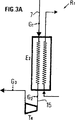
図3A、3Bおよび3Cはそれぞれ、本発明の基本原理、天然ガスの各種の相の温度図、および1つの実施例を示し;
図4は窒素を含むガスを液化するように設計された実施例と、窒素の部分的分離とを示し;
図5は冷却液の混合物を用いる予冷却を遂行する実施例を示し;
図6は窒素を含む天然ガスを液化するための実施例を示し、膨脹によって生成される気体留分の一部がリサイクルされ、冷却ステージが冷却液の混合物を使用して遂行されることを示している。
図1は例えば天然ガスを液化するために従来の技術で使われている方法を示す理論図である。
予冷却サイクルと主冷却サイクルとにおいて液体の混合物が冷却液として使用されている。この混合物は蒸発することによって圧力化にあるガスを冷却して液化する。蒸発後この混合物は水や空気のような手近に使える周囲の媒体との熱交換プロセスによって圧縮され、濃縮されてリサイクルされる。
従来技術のもう一つの方法は窒素のような永久ガスを使って動作するサイクルを使用することである。このタイプのシステムを図2に示す。
天然ガスはパイプ1によって圧力下で送られてくる。それは熱交換器E1の中を通り、液化され冷却される。熱交換器E1の出力で液化された天然ガスは膨脹弁V1を通る時大気圧に近い圧力値になるように膨脹させられてパイプ2経由で引き出される。
天然ガスは冷却サイクルの中を流れる永久ガスによって冷却される。この天然サイクルは、タービンT1と、タービンT1を熱交換器E1に連結するパイプ4と熱交換器から例えばK1、C1、K2、C2のように一連のコンプレッサと冷却手段をカスケードに連結した構成に永久ガスを通す通路を形成するパイプ5とから成る。この冷却サイクルの中を流れる永久ガスは圧縮ステージK1の中で圧縮され、冷却媒体C1を通る時冷却されて圧縮ステージK2に送り込まれる。ここでそれは冷却ステージC2に進む時に冷却される用意として圧縮される。このようにして圧縮され冷却された永久ガスはパイプ3によってタービンT1に移されて膨脹し、そこから冷却されて出てきて、パイプ4によって熱交換器E1に供給される。この方法で冷却された永久ガスは熱交換器E1の中で天然ガスと相互に接触する時天然ガスを冷却する。天然ガスを冷却した後、この熱交換器の出力で永久ガスはパイプ5によって再び圧縮と冷却ステージに戻されてリサイクルされる。
この型のサイクルは特にその簡単さのために小容量のユニットで使われているが、その性能は冷却後の混合物を使用するサイクルのそれに比して顕著に劣る事が認識されている。更にそれは非常に多量の冷却ガスの流れが再循環することを必要とするものである。
窒素のような冷却用に使用する補助永久ガスの代わりに液化すべきガスの留分を同じ機能を果たすために使用することができる。図2で示したサイクルの動作原理はこの原理に対してもそのままあてはまる。
以下に記述する本発明が依拠する原理は濃密相にある天然ガスから出発して、相遷移なしに少くとも部分的に液化されるステージに達する。即ち異なる性質の2つの相が共存するような遷移相になることなしに液化プロセスの少くとも一部が生起することである。それ故液化プロセスを通じて、濃密相から液相への転換が連続的に生起する。遷移相があるとすれば転換が不連続であるということを意味するであろうからである。
この方法は主として2つのステップに依拠する。第1のステップは天然ガスを濃密相にすることから成り、第2のステップは機械エネルギによる膨脹を生じること、例えば天然ガスを濃密相から液相へ変化させる本質的に等エントロピーな膨脹を生成することから成る。
ガスはパイプ7(図3A)によって熱交換器E2のG1点(図3B)によって示される熱力学的状態の中に気相で到着し、熱交換器の中で冷却サイクルR1からの冷却媒体と接触して与えられた温度に予冷却される。熱交換器E2を出る時、天然ガスはG2点(図3B)の濃密相の状態にある。次にパイプ15によって熱交換器E2からタービンT4に移され、膨脹させられる。タービンT4を通った後それはG3点で少くとも部分的に液相になっている。濃密相から液相への転移は機械エネルギによる膨脹によって遷移相なしに生起する。
膨脹後G3点で得られる液相は例えば飽和液相である。膨脹プロセスがこの飽和液相で進行するので気体又は蒸気留分が現われ、これは熱交換プロセスの後リサイクルされるが、どこにでも使用できる。例えば、液化設備のサイドで燃料として使用することもできる。
プロセスは図3Bに示すような圧力(P)と温度(T)のデータを与える図で説明される。この図で2相エリアの中では液相と気相が一緒に起る。この2相エリアの外側に3つのエリアが定義される。気相のエリアは2相エリアからの蒸気ブランチv(液化曲線)と臨界点Cを通る等エントロピー曲線Sとによって区切られている。濃密相のエリアは一方は等エントロピー曲線Sによって、もう一方は臨界点Cを通る等圧線pによって区切られている。液相のエリアは一方は等圧線pによって、又2相エリアとは液体ブランチl(バブル曲線)によって区切られている。
本発明の方法によって天然ガスが受ける変化は、次のようにして生起する:
液化すべき天然ガスは、始め温度TG1で圧力PG1の点G1によって表わされる気相の状態にある。それは次にほぼ等圧の条件下で冷却され、圧力PG2と温度TG2の点G2で表わされる濃密相の状態になる。G1からG2への転換は例えば気相エリアを濃密相エリアから区切る等エントロピー曲線S上のF1点を通り遷移相なしに連続的に行われる。次に濃密相のG2点にある天然ガスはほぼ等エントロピーな過程でG3点で示されるような飽和液相の状態に変えられる。この点は2相エリアの液体ブランチl上にあり、TG3、PG3の温度と圧力の値に対応する。圧力値PG3はほぼ大気圧のそれと等しいことが好ましい。G2点で表わされる状態からG3点で表わされる状態への転換は液相エリアから濃密エリアを区切る等圧線p上の点F2を通って連続的に遷移相なしに行われる。即ち2つの相の共存は起こらない。
前に述べたように膨脹は蒸気又は気体留分を生成することによって2相エリアの中で継続することができる。
本発明の方法の好適な実施例では膨脹ステージに先立つ冷却ステージの終りにおける温度は165から230Kの間の範囲にある。
ステップa)の間7から20MPaの範囲に圧力レベルを維持しながらそのような条件下で動作するためには、気体留分の値が膨脹ステージの終りに最小値よりは大きい、例えば20%である必要があることが分かっている。
図3Cに関する本発明の方法の以下の記述は、天然ガスの液化に対するこの方法の応用を説明するものである。
天然ガスはパイプ7を通って少くともメタンの臨界圧力値よりも高い圧力レベルで熱交換器E2に到達し、例えば165Kと320Kの間の温度範囲まで冷却される。ガスのこの予冷却ステージは熱交換器E2に入る前に天然ガスの一部分をパイプ8によって分路し、この分割された部分を膨脹タービンT2に向けることによって行われる。分けられた部分は膨脹プロセスの間に冷却され、タービンT2の中で気相となりパイプ9によって熱交換器E2に向けられる。そこで分けられて冷却された気体留分は冷媒として使われ、熱交換器E2に入ってくる本流の天然ガスの温度を低下することを可能とする。ガスを冷却させる性能をもつどのような外部の冷媒をこの分けられて冷却された天然ガスの部分の代わりに使ってもよい。
天然ガスは冷却され「濃密」相になって熱交換器E2からパイプ10を経由して出てくる。この「濃密」相のガスの一部分はパイプ11によって例えばタービンT3に直接送られる。タービンT3の出力には例えば大部分が液相になった混合物が得られる。パイプ12によってこの混合物はタービンT3から大気圧に近い圧力でとり出され、分離器フラスコB1に送り込まれ、液体留分と気体留分とが分離される。気体留分はフラスコB1からとり出されてパイプ13によって熱交換器E3に送られる。
熱交換器E2から出てきた「濃密」相の冷却された天然ガスのうちタービンT2に送られなかった部分はパイプ14を介して熱交換器E3に通され、そこでパイプ13を経て入ってきた気相留分との熱交換プロセスによって冷却される。この方法で冷却された天然ガスはこの熱交換器に入った時の温度よりも低い温度で、例えばパイプ13を経て入ってきた気相留分の温度に近い温度で熱交換器E3から出てくる。そしてパイプ13によってタービンT11に送られ膨脹させられる。タービンT4の出力に得られる混合物は大部分が液相で、パイプ16を経て分離器フラスコB1に送られる。フラスコB1に集められた2つの液相の部分が液化された天然ガスを形成し、パイプ17によってとり出される。
このタイプの濃密相、即ち本発明の第1ステップの後1乃至複数個のタービンから得られるような相を膨脹させると、冷却が行われて、例えば最後の膨脹ステージから出てくる時直接に混合物が得られる。この混合物は大抵大気圧に近い圧力で、メタンの沸点温度(111.66K)に近い温度の液相を含む。
前に述べた分離プロセスの後、分離器フラスコB1からの気相留分はパイプ13を通り、更にパイプ18を通って熱交換器E2に送られ、そこから液化すべき天然ガスがプロセスのスタート時点でもっていた温度に近い温度で出てくる。そしてパイプ19を経て圧縮ステージK3に送られる。圧縮ステージK3の終りに気相留分は交換器C3で使える水又は空気のような周囲の媒体との熱交換プロセスによって冷却され、この留分は熱交換器E2の前で始めに分けられた気体の部分にタービンT2で膨脹プロセスを加えて取り出して熱交換器E2に入れ、パイプ20を通してきた気相留分と、交換器C3と圧縮ステージK4との間で混合される。こうして得られた気体混合物は圧縮ステージK4で圧縮され、そこで使える水又は空気のような周囲の媒体との熱交換プロセスによって冷却される。こうして圧縮され冷却された気体混合物はパイプ21を経てリサイクルされ、パイプ7を通って到着する液化すべき天然ガスと混合される。
圧縮ステージK3とK4の各々の代わりに、2つの圧縮ステージを連続したものに置き換える方が有利かも知れない。その場合1つの圧縮ステージを出てくる気体混合物は水又は空気のような使用可能な媒体との熱交換によって冷却されてから次のステージに送られるので、圧縮プロセスが水又は空気のような周囲媒体の温度に近い温度で有効な等温圧縮に近いものになる。
本発明の方法は、少くとも次の2つのステージを具体化することから成る:
1)最初のステップa)の間天然ガスをメタンの臨界圧力より少くとも大きな圧力で、そしてこの冷却ステージの終りに天然ガスが濃密相であることを確実にするような温度で冷却し、
2)ステップa)で得られる濃密相の少くとも一部分をタービンのような機械エネルギでの膨脹によって天然ガスの圧力を減らすように設計された装置で膨脹させ液化させる。濃密相の状態から液相の状態への転換は相の遷移なしで生起する。
膨脹のプロセスは気体留分が現わるまで続け、その後方法は以下のようなステップに移っていく:
3)ステップb)から得られる気体留分と液体留分をステップc)との間に分離し、
4)ステップc)から得られる気体留分をステップd)の間に天然ガスの非膨脹留分との熱交換プロセスを通過させ、この熱交換プロセスの後ステップe)の間にこの非膨脹留分を膨脹させて、液体−蒸気の混合物を形成し、更にこれを液体留分と気体留分とに分離し、
5)ステップc)とe)からの液体留分をステップf)で再統合して、液化天然ガスを形成させ、更に
6)ステップd)からの気体留分を少くとも一部再圧縮してステップa)にリサイクルする。
天然ガスがメタンよりも重い炭化水素を含んでいる場合は、天然ガスを構成する混合物の臨界圧力はメタンの臨界圧力よりも大きい。この場合、ステップa)を遂行する圧力はこの混合物の臨界圧力より大きいことが好ましい。
ステップa)を遂行する圧力は混合物に対してそれ以上の圧力では2相が共存し得ないような圧力値として定義されるクリコンデンバールより大きいことが好ましい。
図3Cに示す例では、タービンT3の中で膨脹させられなかった「濃密」相の天然ガスの部分は熱交換器E3の中で、生成された時の液化天然ガスの最終の温度に近い温度になるように冷却される。
膨脹タービンT3の中で膨脹させられる天然ガスの部分は入力に供給される天然ガスの大分部を占めるが、この部分はパイプ10を通って熱交換器E3の入力に到着する天然ガスの3分の2よりも大きいことが好ましい。
天然ガスを膨脹させる膨脹オペレーションは例えばタービンT3とT4の中で繰り返し行われ、例えば圧縮ステージK3とK4とを、又図5と6とに示す例の場合は圧縮ステージK5とK6とも一緒に、又は後者のみを駆動するのに用いられる。そのため必要となるであろう追加の機械エネルギは、蒸気タービン又は好ましくはガスタービンによって供給される。
同じ回路上の2乃至多数の圧縮ステージと2乃至多数のタービンを設置することが有利であることが多い。
ステップa)を遂行する圧力レベルを高くすることによって天然ガスを液化するために必要な追加の機械的エネルギを減少させることができる。
本発明の方法はステップa)を遂行する圧力が高ければ、殆どすべての場合有利である。加えられる圧力は少くともメタンの臨界圧力(4.6MPa)に等しくなければならず、好ましくは液化すべき天然ガスを構成する混合物のクリコンデンバールよりも大きいことが望まれる。例えば7から20MPaの間にあることが好ましい。
ステップa)の終りにおける温度を低くすることによって、ステップc)によって遂行される膨脹プロセスの終りにリサイクルされる気相の量が減少する。前述したように温度は165Kから230Kの間にあることが好ましい。
天然ガスがメタンより重い炭化水素を含んでいる場合は、この炭化水素は液化プロセスの前に少くとも部分的に天然ガスから分離される。これは特に液化中に結晶化する危険を避けるためである。
圧力がクリコンデンバールより大きい場合は、メタンよりも重い炭化水素は冷却によって濃縮することができない。この場合は、例えばアルミナ、ゼオライト又は活性炭素を含む吸着剤上への吸着プロセスを用いて分離するのがよいことが発見された。
脱着は例えば並列に動作する少くとも2つのベッド中で行う。例えば1つのベッドが吸着オペレーションをしている間に他方のベッドは脱着オペレーションをする。脱着は例えば圧力を減少させ、それと共に/又は温度を上昇させることで行う。メタンより重く分離しなければならない炭化水素は吸着ステージで吸着剤上に付着し、脱着ステージでそこから分離される。
天然ガスが重い炭化水素を含む場合に使うもう1つの方法は、天然ガスをステップa)の間に或る温度まで冷却することである。その温度とはガスを混合物のクリコンデンバールよりも低い圧力レベルまでもってくるほぼ等エントロピー膨脹の終りに液相を遂行凝縮によって形成するような温度である。その後で膨脹した混合物はほぼ一定の圧力で冷却される。分離しなければならないメタンより重い炭化水素を含む液相は、膨脹プロセスの終りおよび/又はそれに続く混合物の冷却の間に分離する。このオペレーションはほぼ一定の圧力の下で遂行する。
天然ガスがメタンより重い炭化水素を含む場合、ステップa)が遂行される圧力よりも低い圧力レベルで行われる事前プロセスの間に分離することも可能である。この場合事前プロセスステージの間の圧力がクリコンデンバールより低いならば、メタンより重い炭化水素は濃縮手段や、蒸留および/又は溶剤への吸着等のような他の周知の手段によって、例えば室温より低い温度で分離することができる。
この事前ステージの終りに、できるだけ等圧圧縮に近い条件下で行われる圧縮ステージによってガスを圧縮して、その中で圧縮ステージを冷却ステージに代える。この冷却は例えば液化するサイトで使用できる空気や水のような冷却用流体を使って行う。
一般的にいってこのような事前圧縮ステージは、液化すべきガスの圧力がステップa)を満足な条件で遂行するのに充分であるような時に使用される。
特に、例えば天然ガスの集積を作業した終りの頃に、ガス圧が井戸の上部であまりに低くなったような時に必要となる。
液化すべきガスが窒素を含む場合、そしてそれが必要ならばこの窒素の或る量を分離することができる。
これは例えば次のような方法で行われる;
天然ガスの混合物と一緒に窒素留分を液化してしまうことなしにステップb)で行われる膨脹プロセスの終りに高い窒素含有率の気相を作り、液化すべき天然ガスに含まれている窒素の少くとも一部分を分離できることが発見された。事実窒素留分が存在する時に天然ガスを液化することは窒素留分の存在が液化オペレーションを困難にすることと、得られた液相から例えば蒸留プロセスによって窒素留分を分離しなければならないことから二重に問題である。
この例では例えば図4に示すような方法で具体化している。
天然ガスはパイプ7を通って熱交換器E2に送られる。熱交換器E2の中での冷却プロセスの終りに天然ガスは「濃密」相の形で出てくる。この「濃密」相留分は以下に記す少くとも2つの連続する膨脹ステージによって直接膨脹させることができる。
濃密相の第1の留分はパイプ11を通して熱交換器E2の出力からタービンT31に送られ、そこで膨脹させられる。この第1の膨脹ステージの終りに膨脹で得られた混合物はパイプ30によってタービンT31から分離器フラスコB2に送られ、そこで気体留分と液体留分とが分離される。気体留分はパイプ31によって例えば熱交換器E3に送られリサイクルされる。
分離器フラスコB2で分離された液体留分の窒素成分は減少されていて、この液体留分はパイプ32を経てタービンT32に出され、そこで膨脹されて、液体、蒸気の混合物の形でとり出される。タービンT32を出て、液体、蒸気混合物はパイプ35によって接触器S1のベース即ち低い部分に運ばれる。
タービンT31に向けられなかった熱交換器E2から出てきた天然ガスの濃密相の冷却された留分(第2の留分)はパイプ14によって熱交換器E3に送られる。この熱交換器の中でこの留分はパイプ31からの気体留分との熱交換プロセスによって冷却される。熱交換器E3を去る時、濃密相のこの留分は始め交換器E3に入ってきた時の温度より低い温度になっていて、ほぼパイプ31を経て到着した気体留分の温度に近くなっている。交換器E3から出てきたこの濃密相の留分はパイプ15によってタービンT4に送り出され、そこで膨張させられる。膨張後タービンT4の出力に得られ、液相の大部分をなす液体蒸気混合物はパイプ36によって接触器S1のヘッド即ち上の部分に送られる。タービンT4を出るこの液相は比較的高い窒素含有率をもつ。この液相は接触器S1の中でパイプ35を経て接触器S1のベースに到着する気体留分と向流接触させられ、その合成物は比較的窒素成分の少ない液相とほぼ平衡状態に近くなる。接触器S1の中で下降する液相は窒素分を減らし、上昇する気相は窒素分をふやす。それ故接触器のベースには比較的窒素成分の少ない液相を得、ヘッドには比較的窒素成分の多い気体留分を得ることができる。接触器S1のベースに集められた液体留分は液化天然ガスを形成し、パイプ38をへてとり出される。接触器のヘッドに集められた気体留分は高窒素濃度気体留分を形成し天然ガスから分離される。
この高い窒素濃度をもつ気体留分はパイプ34からとり出され、熱交換器E4に送られそこからパイプ37によって排出される。熱交換器E4では高窒素濃度をもつ気体留分は、天然ガスの入力パイプ7を直接熱交換器E4に結合するパイプ33を経由して入ってくる天然ガスの一部分との熱交換プロセスによって熱せられる。
直接取入口パイプ7から分路された天然ガスのこの部分は熱交換器E4でこの熱交換によって冷却され、熱交換器E4を接触器S1と連結するパイプ36の途中にある膨脹弁V3を通して膨脹される。この分路され膨脹させられた天然ガスの部分はタービンT4からの液体−蒸気混合物とパイプ36のレベルで混合されて接触器S1に送られる。
接触器S1のヘッドからの気体留分を熱交換器E3とE2とに送ることも可能であるが、この場合追加の熱交換手段をもたなければならない。
接触器は例えば遅延コラム素子乃至はプラットフォームコラムである。接触器S1の理論ステージ数は例えば3又は4である。
本発明の方法の動作するしかたについて以下に述べる。
液化すべき天然ガスが308Kの温度で、150バール圧力であり、7.7質量%の窒素を含むとする。
この天然ガスの第1の留分f1を熱交換器E2とE3で122Kの温度になるまで冷却する。熱交換器E3から出てくる時天然ガスは従って「濃密」相の状態にある。次に少くとも部分的に例えばタービンT4の中で膨脹によって大気圧で液化し、パイプ16によって接触器S1のヘッドに供給する。
熱交換器E2の上流から分路された第2の留分f2をタービンT2の中でその濃縮圧力までほぼ等エントロピー膨脹させることによって185Kまで冷却する。この冷却し膨脹させた留分をパイプ9によって熱交換器E2に供給し、第1の留分f1との向流により加熱する。この熱交換の後にこの留分f2は周囲の媒体によって冷却される一連のコンプレッサK4、C4を通り、その中で圧縮され冷却される。これを入口のパイプ7によって入ってくる液化すべき天然ガスと混合する。
第3の留分f3を熱交換器E2の出力から分路し、タービンT31の中でほぼ等エントロピー膨脹によって例えば117Kまで冷却する。この留分f3をフラスコB2の中で膨脹させることによって得る気体/液体混合物から気体留分を分離して、パイプ31を経て熱交換器E3に送り、そこからパイプ18経由で熱交換器E2に移し、そこで第1の留分f1との向流で熱を奪う。こうして温度上昇させられた後留分f3は一連のコンプレッサK3、C3を通過して、例えば周囲媒体により冷却され、第2の留分f2と混合されて、一連のコンプレッサK4、C4に行って同じように例えば周囲媒体によって冷却される。
フラスコB2からの液体留分は大気圧でタービンT32を通すことによって膨脹させ、これを接触器S1の低い方、例えばベースに導く。接触器の上の方に来ている液体は窒素が多い(6.7質量%)ので、これと接触して蒸気即ち気体留分が窒素を多く含んで生成される。接触器の出力では蒸気留分は質量パーセントで66%の窒素を含み、液化された天然ガスは1.3%の窒素を含むものとなる。この蒸気留分は処理すべき天然ガスの留分f4によって室温まで温度を高められ、排出される前に接触器のヘッドに供給される。
留分f1、f2、f3およびf4は熱交換器との熱的近似が最小になるように選ばれる。
追い出されるガスの中のメタンの損失は3.5%になる。
ステップb)の間に行われる膨脹は例えば50℃以上にもなる温度の大きな変動を伴う。膨脹が2又はそれ以上のタービンで連続して行われる場合、各タービンの入力と出力との温度の間には比較的大きな差が生じる。更に膨脹は「濃密」相又は液相に対して行われる。膨脹中の流体とタービンの素子との間に熱交換があると、こういう条件下では膨脹プロセスの効率を低下することになる。
膨脹プロセスがあまり熱伝導的でない材料で作られた素子から成るタービンの中で行われる方が有利であることが分かった。これらの素子はこのように天然ガスから熱的に絶縁されるようにする。
これらの素子は金属製であっても熱的絶縁層で蔽われていればよい。これらの素子特にロータは熱伝導率の低い合成材料から作る。
ステップa)とb)との間に起る熱交換は向流、熱交換器によって行われる。これらの熱交換器は例えば多通路交換器であり、プレート交換器であることが好ましい。プレート交換器は例えば鑞付けされたアルミニウムから成る。プレートを相互に熔接したステンレス スチールの交換器を使うこともできる。
熱交換に使う液体が中を通るパイプは種々の方法で作ることができる。例えば2枚のプレートの間に波形の分離用プレートをはさむとか、溝つき板や化学的彫版によるものを重ねること等によってプレートを形成するとかの方法がある。
巻いたパイプの熱交換器を使用することもできる。この場合ステップe)の熱交換を交換器の最も冷たい側で好ましくは5K以下、最も熱い側で好ましくは10K以下の温度差で行う。
ステップa)の冷却に冷媒の混合物で動作する外部サイクルを応用することも本発明の範囲内で可能である。この例による動作原理を例えば図5に示す。
この例では天然ガスを冷却する第1ステージはプレート熱交換器のような交換器E2の中で行われ、冷却された気体留分を用いる膨脹による熱交換の代わりに冷媒の混合物を用い、これを交換器E2内で蒸発させる。
冷媒の混合物は一組のパイプやコンプレッサや熱交換器等から成るサイクルAからきて、以下に述べるように展開する。
冷媒の混合物は冷却が起る温度範囲を増加させるために連続している2つの圧力レベルで蒸発させる。
混合物は例えばパイプ27によって交換器E2の中に供給されるが、2つのパイプ27aと27bとに分けられて出力される。液相である冷媒の混合物の第1の部分はパイプ27aの延長部分を形成するパイプ23によってとり出されて交換器E2から第1の膨脹弁V20に行き、そこで例えば238Kから303Kまでの範囲の温度で蒸発させられ、パイプ24によって交換器E2の中を通って気体又は蒸気の形で圧縮器K6に送られる。
混合物の第2の部分はパイプ27bを通って交換器E2からとり出されてパイプ27bの延長パイプ25上にある弁30に入る。混合物は弁30によって膨脹させられて大気圧に近い圧力レベルになり、例えば173Kと238Kとの間の範囲の温度で蒸発させられる。こうして得られた蒸気相は交換器E2を通ってコンプレッサK5の入力に送られ、その後にある交換器C5の中で冷却されて、パイプ24を通ってくる蒸気留分と混合される。こうして得られた蒸気相の混合物は、次にコンプレッサK6の中で圧縮され、冷却され、交換器C6を通ることによって濃縮されて、パイプ27によって交換器E2に供給され、そこで少し冷却されてから膨脹させられて蒸発する。
天然ガスはパイプ7を経て交換器E2に到着し、冷却されてパイプ11を経て交換器E2を出る。交換器E2を出る時、混合物の形で出てきて、その温度は例えば178Kに近いものである。この混合物の大部分はタービンT3を通ってその中で膨脹させられて、液体−蒸気混合物の形で出てくる。そしてパイプ12を経て接触器S1のベースに供給される。
タービンT3に行かなかった天然ガスのもう一方の部分は交換器E2からパイプ14によって直接プレート交換器E3に送られ、そこで例えば接触器S1からパイプ13経由でくる蒸気相の留分との熱交換によって冷却され、その温度が生成される液化天然ガスの最終温度に近い温度に達する。
交換器E3の中で冷却された気体留分はパイプ15によってとり出され、膨脹弁V4を通って膨脹される。膨脹によって得られた液体留分は接触器S1のヘッドに送られる。
接触器S1の中でこの液相は窒素を奪われ、一方接触器の底部に供給された蒸気相は接触器の中を上昇してきて、窒素を奪って窒素成分が多くなる。蒸気相の留分がこのように窒素を負荷されて接触器を出ていくので、天然ガスに当初含まれていた窒素の大部分は排除される。
窒素の豊富な気体留分は交換器E3を通り、パイプ18を経由して交換器E2に入り、そこからパイプ19を経て出ていく。
窒素を奪われた液体留分から結果する液化天然ガスは接触器S1の低い部分からとり出される。
接触器S1は例えばプラットフォーム コラムか遅延コラム等である。遅延コラムが使われる時には遅延が「構造」型のものである方が有利である。
図5に実施例の1つとして示す図に対しては本発明の範囲内で種々の修飾が考えられる。
特に交換器E2の中で行われる冷却ステージの間に液相の混合物を膨脹させる圧力レベルの数を修飾することが可能である。図5に示す説明においては2つの圧力レベルであったが、これを1つに減らしてもよく、又反対に3又はそれ以上にしてもよい。膨脹圧力レベルの数を増加することによって必要な圧力パワーを減らすことができるが、設備の複雑さは増加する。圧力膨脹レベルを幾つにするかの選択は従って技術対経済のかね合いである。
膨脹弁V20、V30およびV4は全部又は一部をモータによる膨脹タービンによって代行させてもよい。
熱交換器E2とE3とは異なる材料および/又は組み立て構成から作られるものでもよい。又一連の熱交換器を1つの単プレート交換器で構成することも可能である。
コンプレッサK5とK6とはそれぞれが一連のステージをもつものでもよい。2つの連続するステージの間に中間の冷却の為のステージを設けてもよい。
パイプ19にとり出される低圧力気体留分の少くとも一部分を再圧縮しリサイクルしてもよい。明らかにこのようにして得られた気体留分を低い圧力で使えるから、必要な資本費用と運用費とをかなり軽減できるのである。
天然ガスが窒素を含有する場合、比較的窒素の少ない気体留分をリサイクルし、比較的窒素の多い気体留分を排出してしまうことは有利である。この場合図6の線図に示すようにしてプロセスを進めることができる。
図6に示す構成において交換器E2からパイプ11によつて出てくる天然ガスはタービンT31の中で第1の膨脹をうける。タービンT31の出力において液体留分はフラスコB3によって集められ、好ましくはこのフラスコの低い部分に位置するパイプ42経由で取り出されてタービンT32に行き、そこで第2の膨脹プロセスをうける。フラスコの上の部分には比較的窒素の多い気体留分が集められ、パイプ40によって、タービンT4に供給されて、そこで膨脹させらせ、接触器S1の好ましくは低い部分に送られる。タービンT32を出る時、膨脹した混合物がパイプ43経由でとり出され、フラスコB4の中で液体留分と気体留分とに分離される。液体留分は窒素含有率の小さいもので、好ましくはフラスコBの低い部分に位置するパイプ45を経てとり出され、生成される液化天然ガスの一部を形成する。気体留分はフラスコの上の部分からとり出されるが、比較的窒素を少なく含むもので、パイプ44を経て交換器E3に送られ、更にパイプ18経由で交換器E2に送られて、そこからパイプ19を経て出ていく。パイプ19はコンプレッサK3に連結していて、これが例えば窒素含有率の小さい気体留分を再圧縮して交換器C3に移し、ここでこれを水や空気のような冷却用流体によって冷却する。コンプレッサK3は例えば数段の圧縮ステージを統合したもので、その間に冷却ステージもあるものであることが好ましい。
パイプ15経由で熱交換器E3を出る圧力をかけられた天然ガスは、例えば、膨脹弁11で膨脹させられて接触器S1のヘッドに供給される。
接触器S1の中で上昇してきて液相と接触した結果として窒素を多く含むようになった気体留分はパイプ46経由で接触器を去り、交換器E4に供給され、そこからパイプ49を経て部分的にリサイクルすることもできる。圧力下の天然ガスの一部分はパイプ47を通って交換器E4に到達し、交換器E4の中で冷却されて、生成されるLNGの最終温度に近い温度になって、パイプ48経由で出ていく。この部分は弁V10を通して膨脹させられ、接触器S1のヘッドに供給される。
接触器S1のベースには液体留分が集められ、これはパイプ45経由で到着する液体留分と混合されて、生成すべき液化天然ガスを形成し、パイプ50を経由してとり出される。
機械的エネルギによって膨脹を可能とする上記以外の機器をタービンの代わりに使ったとしても、それは本発明の範囲から離れるものではない。
明らかに種々の修飾および/又は追加を、実施例を非制限的な方法で説明した上述の方法および装置に対して行うことが当業者にとって可能であるが、それらも本発明の範囲から逸脱するものではない。Liquefaction of natural gas is an important industrial process that allows it to be transported and stored over long distances by tanker in liquid form.
Conventionally used "natural gas" liquefaction methods consist of passing natural gas through a heat exchanger and cooling it using an external cooling cycle. U.S. Pat. Nos. 3,735,600 and 3,433,026 disclose liquefaction methods in which gas is supplied to one or several heat exchangers and liquefied. Throughout this specification, "natural gas" means a mixture that is predominantly methane but may also contain other hydrocarbons and nitrogen, in any form (gas, liquid or both). Including. In the beginning, natural gas is most often in the gas phase, but can take different forms during the liquefaction process, and there can be moments when the liquid phase and the gas phase coexist.
In the liquefaction process, an external cooling cycle is performed using a mixed fluid as a cooling fluid. By evaporation, such a mixed fluid cools and liquefies the natural gas under pressure. After the mixture has evaporated, it is compressed and concentrated by heat exchanger treatment with a rich medium such as water or air.
Such methods are complex and require the use of high heat exchange surface areas and high compressive forces. Therefore, capital investment increases.
After the first cooling stage, it has been discovered that natural gas can be cooled and liquefied directly from a "dense" phase by expansion in a turbine. This is the purpose of the present invention. The expression "dense" phase refers to a phase which can be obtained from the initial gas phase by means of isobaric expansion without phase transition, and this phase is liquid without phase transition as a result of isentropic expansion. It becomes a phase. At least part of the liquefaction process occurs without a transition phase, ie the change from the gas phase to the liquid phase occurs continuously without a phase transition in which two different phases are present simultaneously. Natural gas is brought into a "dense" phase by applying a pressure at least above the critical pressure of methane before expansion and by lowering the temperature of the "natural gas".
The present invention relates to a method for liquefying natural gas. It is characterized in that it comprises at least one step in which at least a part of this gas is liquefied by expansion by mechanical energy. This expansion changes the natural gas from a dense phase to a liquid phase.
The transition between the two states occurs without a phase transition, ie, without two different phases at the same time.
The method comprises, for example, at least two steps:
a) cooling the natural gas at a pressure at least equal to or greater than the critical pressure of methane and at a temperature such that at the end of the cooling process, the natural gas assumes a dense phase form;
b) At least one fraction of this dense phase obtained from step a) is separated from the dense phase in a device designed to reduce the pressure of natural gas by expansion with mechanical energy The liquid phase is expanded and liquefied such that the change to the liquid state occurs without a phase transition, and at least partially forms liquefied natural gas.
The pressure level of the liquefied natural gas at the end of step b) is approximately atmospheric.
The expansion process of the liquid phase obtained during step b) continues until a gaseous fraction appears, and the process can proceed to the next step:
Separating the liquid and gas fractions during step c),
The gaseous fraction resulting from step c) is subjected to a heat exchange process for the non-expanded natural gas fraction during step d) to form a liquid-vapor mixture, which is further separated into a liquid fraction and a gaseous fraction. After this heat exchange process during the separating step e), the unexpanded fraction is expanded:
Recombining the liquid fractions from steps c) and e) to form liquid natural gas;
Recompressing and recycling at least a portion of the gaseous fraction from steps c) and e) to step a),
The gas fraction obtained at the end of step b) is greater than or equal to 20%.
Devices used to expand natural gas and change from a dense phase to a liquid phase are, for example, turbines.
During step a), the natural gas is cooled by a heat exchange process using a gas fraction from the natural gas. This gas fraction is expanded in a turbine, and the expanded gas fraction is at least partially recompressed and recycled in a compression process.
At least one recycled gas fraction is compressed in two steps, during which time the gas is cooled by the surrounding refrigerant at the end of each of its compression stages.
During step a) the natural gas is also cooled by evaporating the mixture of the cooling liquid. The mixture obtained in this way is in the vapor or gas phase. It is then compressed and concentrated by a process of heat exchange with the surrounding refrigerant, expanded and recycled.
The mixture of cooling liquids is expanded and evaporated at at least two pressure levels.
If the natural gas contains heavy hydrocarbons, the heaviest hydrocarbons contained in the natural gas to be liquefied are separated by an adsorption stage before step a).
Step a) is performed at a pressure level greater than the critical pressure of methane. Pressure levels greater than the critical pressure of the mixture comprising natural gas are preferred.
Preferably step a) is carried out at a pressure level above which the natural gas to be liquefied is chrycondenebar (maximum pressure such that the two phases can coexist).
Step a) is preferably performed at a pressure level ranging from 7 to 20 MPa.
The temperature of the natural gas at the end of step a) is preferably in the range between 165K and 230K.
In the case of natural gas containing hydrocarbons heavier than methane, at least a portion of the hydrocarbons is separated during the preparation phase at a pressure level lower than the pressure level of step a).
When the natural gas expands to a certain temperature during step a), after expansion a liquid fraction condensed with hydrocarbons heavier than methane is produced and separated.
Step b) is carried out, for example, by expansion in a turbine, the components of which have poor thermal conductivity and are thermally separated from the gas.
Step b) is performed, for example, by expansion in a turbine with a rotor made of synthetic material.
The heat exchange performed during steps a) and d) is performed by passing the gas through a countercurrent heat exchanger.
The heat exchange process of step d) can be realized by passing the natural gas through a heat exchanger having a temperature difference of 5K or less on the lowest temperature side of the heat exchanger and 10K or less on the highest temperature side.
The expansion during step b) can be performed using at least two turbines in series. The liquid-vapor mixture from the first partial expansion is separated into a gaseous fraction and a liquid fraction, the gaseous fraction proceeds to step d) and the remaining liquid fraction is expanded in a second turbine and this After the second expansion, it forms part of the liquefied natural gas produced by this method.
At least a portion of the gaseous fraction from step b) is brought into contact with the liquid fraction from step e), for example in a countercurrent heat exchanger, after which the resulting liquid fraction is from the liquid fraction from step b) To form liquefied natural gas. The remaining gas fraction is recombined with the gas fraction from step e) to form at least a part of the nitrogen-rich gas fraction, which gas fraction is rejected.
The invention also relates to a device designed to implement the method described above.
The device comprises at least one device E2 which allows the natural gas to be liquefied to be cooled to a concentrated phase, and at least one cooling means R1, wherein the device E2 comprises Characterized in that it is directly connected to at least one means T4 capable of expanding it to liquefy it.
Means or devices capable of expanding natural gas in enriched form include at least one expansion turbine in which at least one element is made from a material having poor thermal conductivity. As a result, heat transfer to the elements of the turbine due to heat conduction that may reduce cooling efficiency due to expansion is eliminated.
The present invention offers a number of advantages over the methods currently used in the prior art. Operating at an initial gas pressure value greater than that used in the methods described in the prior art makes it possible to reduce the energy required to liquefy natural gas.
Furthermore, by directly liquefying the natural gas by expansion, the required surface area of the heat exchanger can be reduced and the method of liquefaction can be simplified, thereby reducing capital costs.
The invention will be better understood and its advantages will become clear from the description of some non-limiting examples illustrated by the following drawings:
FIG. 1 illustrates one example of a prior art cooling cycle with a pre-cooling cycle;
FIG. 2 describes an example of a prior art cycle using permanent gas;
3A, 3B and 3C respectively show the basic principle of the present invention, temperature diagrams of various phases of natural gas, and one example;
Figure 4 shows an embodiment designed to liquefy a nitrogen-containing gas and partial separation of nitrogen;
FIG. 5 shows an embodiment for performing pre-cooling using a mixture of coolants;
FIG. 6 shows an embodiment for liquefying natural gas containing nitrogen, showing that a part of the gas fraction produced by expansion is recycled and the cooling stage is performed using a mixture of cooling liquid. ing.
FIG. 1 is a theoretical diagram showing a method used in the prior art to liquefy natural gas, for example.
A mixture of liquids is used as the cooling liquid in the pre-cooling cycle and the main cooling cycle. The mixture cools and liquefies the gas under pressure by evaporation. After evaporation, the mixture is compressed, concentrated and recycled by a heat exchange process with a readily available surrounding medium such as water or air.
Another prior art method is to use a cycle that operates using a permanent gas such as nitrogen. This type of system is shown in FIG.
Natural gas is sent under pressure by pipe 1. It passes through heat exchanger E1 and is liquefied and cooled. The natural gas liquefied at the output of the heat exchanger E1 is expanded so as to have a pressure value close to the atmospheric pressure when passing through the expansion valve V1, and is withdrawn through the pipe 2.
Natural gas is cooled by permanent gas flowing through the cooling cycle. This natural cycle has a configuration in which a series of compressors and cooling means are connected in cascade, such as K1, C1, K2, C2, from the turbine T1, the pipe 4 connecting the turbine T1 to the heat exchanger E1, and the heat exchanger. And a
Although this type of cycle is used in small volume units, especially for its simplicity, it has been recognized that its performance is significantly inferior to that of a cycle using a cooled mixture. Furthermore, it requires that a very large stream of cooling gas be recirculated.
Instead of an auxiliary permanent gas used for cooling, such as nitrogen, a fraction of the gas to be liquefied can be used to perform the same function. The operating principle of the cycle shown in FIG. 2 applies to this principle as it is.
The principle on which the invention described below rests starts from natural gas in a dense phase and reaches a stage where it is at least partially liquefied without phase transition. That is, at least a portion of the liquefaction process occurs without a transition phase in which two phases of different properties coexist. The conversion from the dense phase to the liquid phase therefore occurs continuously throughout the liquefaction process. This is because the presence of a transition phase would mean that the transition is discontinuous.
This method mainly relies on two steps. The first step consists of bringing the natural gas into a dense phase and the second step produces an expansion due to mechanical energy, for example producing an essentially isentropic expansion which changes the natural gas from a dense phase to a liquid phase It consists of doing.
The gas arrives in the gas phase by pipe 7 (FIG. 3A) in the thermodynamic state indicated by the point G1 (FIG. 3B) of the heat exchanger E2, in which the cooling medium from the cooling cycle R1 Pre-cooled to a given temperature on contact. Upon leaving heat exchanger E2, the natural gas is in a dense phase at point G2 (FIG. 3B). Next, the heat is transferred from the heat exchanger E2 to the turbine T4 by the
The liquid phase obtained at point G3 after expansion is, for example, a saturated liquid phase. As the expansion process proceeds in this saturated liquid phase, a gas or vapor fraction appears, which is recycled after the heat exchange process, but can be used anywhere. For example, it can be used as fuel on the side of a liquefaction facility.
The process is illustrated in a diagram that provides pressure (P) and temperature (T) data as shown in FIG. 3B. In this figure, a liquid phase and a gas phase occur together in a two-phase area. Three areas are defined outside the two-phase area. The gas phase area is delimited by a vapor branch v (liquefaction curve) from the two-phase area and an isentropic curve S passing through the critical point C. The dense phase area is delimited on the one hand by an isentropic curve S and on the other hand by an isobar p passing through a critical point C. The liquid phase area is delimited on the one hand by an isobar p and on the other hand by a liquid branch 1 (bubble curve).
The changes experienced by natural gas by the method of the present invention occur as follows:
The natural gas to be liquefied begins with the temperature T G1 With pressure P G1 In the gas phase represented by the point G1. It is then cooled under nearly equal pressure conditions and the pressure P G2 And temperature T G2 At the point G2. The conversion from G1 to G2 is performed continuously, for example, without a transition phase through the point F1 on the isentropic curve S separating the gas phase area from the dense phase area. Next, the natural gas at the point G2 in the dense phase is transformed into a saturated liquid phase as shown by the point G3 in an almost isentropic process. This point is on the liquid branch 1 in the two-phase area and T G3 , P G3 Temperature and pressure values. Pressure value P G3 Is preferably approximately equal to that of atmospheric pressure. The transition from the state represented by the point G2 to the state represented by the point G3 is performed continuously without a transition phase through the point F2 on the isobar p separating the dense area from the liquid phase area. That is, the two phases do not coexist.
As mentioned earlier, expansion can be continued in the two-phase area by creating a vapor or gaseous fraction.
In a preferred embodiment of the method according to the invention, the temperature at the end of the cooling stage preceding the expansion stage is in the range between 165 and 230K.
To operate under such conditions while maintaining a pressure level in the range of 7 to 20 MPa during step a), the value of the gas fraction should be greater than the minimum at the end of the expansion stage, for example 20%. I know it needs to be.
The following description of the method of the present invention with reference to FIG. 3C illustrates the application of this method to the liquefaction of natural gas.
The natural gas reaches the heat exchanger E2 via the pipe 7 at a pressure level at least above the critical pressure value of methane and is cooled, for example, to a temperature range between 165K and 320K. This pre-cooling stage of the gas is performed by shunting a portion of the natural gas by
The natural gas is cooled and enters the "dense" phase from the heat exchanger E2 via the
The portion of the `` dense '' phase cooled natural gas coming out of heat exchanger E2 that was not sent to turbine T2 was passed through
When expanding a dense phase of this type, i.e. a phase obtained from one or more turbines after the first step of the invention, cooling takes place, for example directly upon exiting the last expansion stage. A mixture is obtained. This mixture usually contains a liquid phase at a pressure close to atmospheric pressure and a temperature close to the boiling point of methane (111.66 K).
After the separation process described above, the gaseous fraction from separator flask B1 passes through
Instead of each of the compression stages K3 and K4, it may be advantageous to replace the two compression stages with successive ones. The gaseous mixture exiting one compression stage is then cooled by heat exchange with a usable medium such as water or air before being sent to the next stage, so that the compression process takes place in the surroundings such as water or air. At a temperature close to the temperature of the medium, it becomes close to effective isothermal compression.
The method of the invention consists of embodying at least two stages:
1) cooling the natural gas during the first step a) at a pressure at least above the critical pressure of methane and at the end of this cooling stage at a temperature which ensures that the natural gas is in a dense phase;
2) At least a portion of the dense phase obtained in step a) is expanded and liquefied in an apparatus designed to reduce the pressure of natural gas by expansion with mechanical energy, such as a turbine. The conversion from the dense phase to the liquid phase occurs without a phase transition.
The expansion process continues until a gaseous fraction appears, after which the method moves on to the following steps:
3) separating the gaseous and liquid fractions obtained from step b) between step c),
4) passing the gas fraction obtained from step c) through a heat exchange process with the non-expanded fraction of natural gas during step d), after this heat exchange process during the non-expanded fraction Expanding the fraction to form a liquid-vapor mixture, which is further separated into a liquid fraction and a gas fraction,
5) the liquid fraction from steps c) and e) is re-integrated in step f) to form a liquefied natural gas,
6) Recompress at least partly the gas fraction from step d) and recycle to step a).
If the natural gas contains hydrocarbons heavier than methane, the critical pressure of the mixture that makes up the natural gas is greater than the critical pressure of methane. In this case, the pressure at which step a) is performed is preferably greater than the critical pressure of the mixture.
The pressure at which step a) is carried out is preferably greater than chrycondene bar, defined as a pressure value above which no two phases can coexist with the mixture.
In the example shown in FIG.3C, the portion of the "dense" phase natural gas that was not expanded in turbine T3 is in heat exchanger E3 at a temperature close to the final temperature of the liquefied natural gas as produced. It is cooled to become.
The portion of natural gas that is expanded in the expansion turbine T3 makes up the majority of the natural gas supplied to the input, but this portion is three minutes of the natural gas arriving at the input of heat exchanger E3 through
The expansion operation for expanding the natural gas is carried out repeatedly, for example in turbines T3 and T4, for example with the compression stages K3 and K4 and, in the example shown in FIGS. 5 and 6, together with the compression stages K5 and K6. Or it is used to drive only the latter. The additional mechanical energy that would be required for this is provided by a steam turbine or, preferably, a gas turbine.
It is often advantageous to install two to many compression stages and two to many turbines on the same circuit.
By increasing the pressure level at which step a) is performed, the additional mechanical energy required to liquefy natural gas can be reduced.
The method according to the invention is advantageous in almost all cases if the pressure for performing step a) is high. The pressure applied must be at least equal to the critical pressure of methane (4.6 MPa), and is preferably greater than the chrycondene bar of the mixture comprising the natural gas to be liquefied. For example, it is preferably between 7 and 20 MPa.
By lowering the temperature at the end of step a), the amount of gas phase recycled at the end of the expansion process performed by step c) is reduced. As mentioned above, the temperature is preferably between 165K and 230K.
If the natural gas contains hydrocarbons heavier than methane, the hydrocarbons are at least partially separated from the natural gas prior to the liquefaction process. This is especially to avoid the risk of crystallization during liquefaction.
If the pressure is greater than chrycondenebar, hydrocarbons heavier than methane cannot be concentrated by cooling. In this case, it has been found that it is better to separate using, for example, an adsorption process on an adsorbent containing alumina, zeolite or activated carbon.
Desorption takes place, for example, in at least two beds operating in parallel. For example, while one bed is performing an adsorption operation, the other bed is performing a desorption operation. Desorption is performed, for example, by reducing the pressure and / or increasing the temperature. Hydrocarbons that must be separated heavier than methane deposit on the adsorbent in the adsorption stage and are separated therefrom in the desorption stage.
Another method used when the natural gas contains heavy hydrocarbons is to cool the natural gas to a certain temperature during step a). The temperature is such that at the end of the nearly isentropic expansion bringing the gas to a pressure level lower than the chrysondenebar of the mixture, a liquid phase is formed by performing condensation. Thereafter, the expanded mixture is cooled at a substantially constant pressure. The liquid phase containing hydrocarbons heavier than methane that must be separated separates at the end of the expansion process and / or during subsequent cooling of the mixture. This operation is performed under approximately constant pressure.
If the natural gas contains hydrocarbons heavier than methane, it is also possible to separate during a pre-process performed at a pressure level lower than the pressure at which step a) is performed. In this case, if the pressure during the pre-processing stage is below chrycondene bar, the hydrocarbons heavier than methane may be concentrated by other well-known means, such as distillation and / or adsorption to solvents, for example above room temperature. Can be separated at lower temperatures.
At the end of this pre-stage, the gas is compressed by a compression stage performed under conditions as close as possible to isobaric compression, in which the compression stage is replaced by a cooling stage. This cooling is performed using a cooling fluid, such as air or water, available at the liquefaction site.
Generally, such a precompression stage is used when the pressure of the gas to be liquefied is sufficient to carry out step a) under satisfactory conditions.
This is particularly necessary when the gas pressure has become too low at the top of the well, for example, at the end of working on natural gas accumulation.
If the gas to be liquefied contains nitrogen, and if necessary, some amount of this nitrogen can be separated off.
This is done, for example, in the following way:
At the end of the expansion process carried out in step b), a gas phase with a high nitrogen content is produced without liquefaction of the nitrogen cut with the mixture of natural gas and the nitrogen contained in the natural gas to be liquefied. It has been discovered that at least a portion of can be separated. In fact, the liquefaction of natural gas when a nitrogen fraction is present makes the liquefaction operation difficult, and that the nitrogen fraction must be separated from the resulting liquid phase, for example by a distillation process. From double is a problem.
In this example, for example, the method is embodied as shown in FIG.
Natural gas is sent to heat exchanger E2 through pipe 7. At the end of the cooling process in heat exchanger E2, the natural gas comes out in the form of a "dense" phase. This "dense" phase fraction can be expanded directly by at least two successive expansion stages described below.
The first fraction of the dense phase is sent via
The nitrogen fraction of the liquid fraction separated in the separator flask B2 is reduced, and this liquid fraction is discharged via a
The cooled fraction (second fraction) of the dense phase of the natural gas coming out of the heat exchanger E2, which was not directed to the turbine T31, is sent by the
This high nitrogen gas fraction is withdrawn from the
This part of the natural gas shunted from the direct intake pipe 7 is cooled by this heat exchange in the heat exchanger E4 and expanded through the expansion valve V3 in the middle of the
It is also possible to send the gaseous fraction from the head of the contactor S1 to the heat exchangers E3 and E2, but in this case additional heat exchange means must be provided.
The contactor is, for example, a delay column element or a platform column. The number of theoretical stages of the contactor S1 is, for example, three or four.
The manner in which the method of the present invention operates is described below.
Suppose that the natural gas to be liquefied is at a temperature of 308 K, a pressure of 150 bar and contains 7.7% by weight of nitrogen.
The first fraction f1 of this natural gas is cooled in the heat exchangers E2 and E3 to a temperature of 122K. When exiting the heat exchanger E3, the natural gas is thus in a "dense" phase. It is then liquefied at least partially at atmospheric pressure, for example by expansion in a turbine T4, and is fed via
The second fraction f2, shunted from upstream of heat exchanger E2, is cooled to 185K by substantially isentropic expansion in turbine T2 to its concentrated pressure. The cooled and expanded fraction is supplied to the heat exchanger E2 through the pipe 9 and heated by the countercurrent with the first fraction f1. After this heat exchange, this fraction f2 passes through a series of compressors K4, C4 cooled by the surrounding medium, in which it is compressed and cooled. This is mixed with the incoming natural gas to be liquefied by the pipe 7.
The third fraction f3 is shunted from the output of the heat exchanger E2 and is cooled to, for example, 117K in the turbine T31 by almost isentropic expansion. The gaseous fraction is separated from the gas / liquid mixture obtained by expanding this fraction f3 in the flask B2 and sent to the heat exchanger E3 via the pipe 31 and from there to the heat exchanger E2 via the
The liquid fraction from flask B2 is expanded by passing it through a turbine T32 at atmospheric pressure, leading it to the lower side of contactor S1, for example the base. The liquid coming to the top of the contactor is rich in nitrogen (6.7% by weight), so that in contact therewith a vapor or gaseous fraction is produced rich in nitrogen. At the output of the contactor, the vapor fraction contains 66% nitrogen by mass and the liquefied natural gas contains 1.3% nitrogen. This vapor fraction is heated to room temperature by the natural gas fraction f4 to be treated and is fed to the head of the contactor before being discharged.
Fractions f1, f2, f3 and f4 are chosen such that the thermal approximation to the heat exchanger is minimized.
The loss of methane in the expelled gas amounts to 3.5%.
The expansion that takes place during step b) is accompanied by large fluctuations in the temperature, for example, even higher than 50 ° C. If the expansion is performed sequentially on two or more turbines, there will be a relatively large difference between the input and output temperatures of each turbine. Further expansion is performed on the "dense" or liquid phase. Heat exchange between the expanding fluid and the elements of the turbine will reduce the efficiency of the expansion process under these conditions.
It has been found to be advantageous if the expansion process takes place in a turbine consisting of elements made of a less thermally conductive material. These elements are thus thermally insulated from natural gas.
These elements may be made of metal as long as they are covered with a thermal insulating layer. These elements, especially the rotor, are made of a synthetic material with low thermal conductivity.
The heat exchange taking place between steps a) and b) is carried out by countercurrent, heat exchangers. These heat exchangers are for example multi-pass exchangers, preferably plate exchangers. The plate exchanger is made of, for example, brazed aluminum. A stainless steel exchanger with plates welded together can also be used.
The pipe through which the liquid used for heat exchange passes can be made in various ways. For example, there is a method in which a wave separation plate is sandwiched between two plates, or a plate is formed by stacking a grooved plate or a plate formed by chemical engraving.
Rolled pipe heat exchangers can also be used. In this case, the heat exchange of step e) is carried out with a temperature difference of preferably less than 5K on the coldest side of the exchanger and preferably less than 10K on the hottest side.
It is also possible within the scope of the invention to apply an external cycle operating with a mixture of refrigerants for the cooling of step a). FIG. 5 shows an operation principle according to this example, for example.
In this example, the first stage of cooling the natural gas takes place in an exchanger E2, such as a plate heat exchanger, which uses a mixture of refrigerants instead of heat exchange by expansion using a cooled gas fraction. Is evaporated in exchanger E2.
The refrigerant mixture comes from cycle A, which consists of a set of pipes, compressors, heat exchangers, etc. and evolves as described below.
The mixture of refrigerants is evaporated at two successive pressure levels in order to increase the temperature range in which the cooling takes place.
The mixture is fed into the exchanger E2 by, for example, a
A second portion of the mixture is withdrawn from exchanger E2 through
Natural gas arrives at exchanger E2 via pipe 7 and is cooled and exits exchanger E2 via
The other part of the natural gas that did not go to turbine T3 is sent from exchanger E2 by
The gas fraction cooled in exchanger E3 is withdrawn by
In the contactor S1, this liquid phase is deprived of nitrogen, while the vapor phase supplied to the bottom of the contactor rises up in the contactor and deprives of nitrogen to increase the nitrogen component. The vapor phase fraction thus leaves the contactor, loaded with nitrogen, so that most of the nitrogen originally contained in the natural gas is eliminated.
The nitrogen-rich gas fraction passes through exchanger E3, enters exchanger E2 via
Liquefied natural gas resulting from the liquid fraction deprived of nitrogen is withdrawn from the lower part of the contactor S1.
The contactor S1 is, for example, a platform column or a delay column. When delay columns are used, it is advantageous if the delay is of the "structure" type.
Various modifications are possible within the scope of the invention for the diagram shown as one of the embodiments in FIG.
In particular, it is possible to modify the number of pressure levels at which the liquid-phase mixture expands during the cooling stage performed in exchanger E2. In the description shown in FIG. 5, there are two pressure levels, but this may be reduced to one, or conversely, three or more. The required pressure power can be reduced by increasing the number of inflation pressure levels, but the complexity of the equipment is increased. The choice of the pressure inflation level is therefore a trade-off between technology and economy.
The expansion valves V20, V30 and V4 may be entirely or partially substituted by a motor-driven expansion turbine.
Heat exchangers E2 and E3 may be made from different materials and / or assembled configurations. It is also possible to configure a series of heat exchangers with one single plate exchanger.
Each of the compressors K5 and K6 may have a series of stages. A stage for intermediate cooling may be provided between two successive stages.
At least a portion of the low pressure gas fraction withdrawn into
If the natural gas contains nitrogen, it is advantageous to recycle the relatively nitrogen-poor gas fraction and discharge the relatively nitrogen-rich gas fraction. In this case, the process can proceed as shown in the diagram of FIG.
In the configuration shown in FIG. 6, the natural gas exiting from the exchanger E2 via the
The pressurized natural gas exiting the heat exchanger E3 via the
The gaseous fraction rising in the contactor S1 and coming into contact with the liquid phase and becoming rich in nitrogen leaves the contactor via a
At the base of the contactor S1, a liquid fraction is collected, which is mixed with the liquid fraction arriving via the
The use of other equipment, which allows expansion by mechanical energy, instead of the turbine, does not depart from the scope of the present invention.
Obviously, it is possible for those skilled in the art to make various modifications and / or additions to the above-described methods and devices, the embodiments of which have been described in a non-restrictive manner, which also depart from the scope of the present invention. Not something.
Claims (24)
a)天然ガスをメタンの臨界圧力より大きいか少なくとも等しい圧力で、この冷却ステップの終りに該天然ガスが濃密相になり、そして該ガスがリサイクルされた気体 留分と代わる代わるに混合されるような温度で冷却され るステップ、
a')濃密相中の冷却された天然ガスを第一のより大きな 留分(11)と第二の残りの留分(14)の二つの留分に分 離するステップ、
b)ステップa')からの第一のより大きな留分を、この ステップb)の終りに液体留分と気体留分を得るため、機械的エネルギーによる膨張によって天然ガスの圧力を減少させるように設定された装置(T3)によって膨張させて液化するステップ、
c)ステップb)中に得られた液体留分と気体留分(1 3)を分離するステップ(B1)、
d)ステップc)で得られた気体留分(13)を膨張され ていなかった天然ガスの第二の残りの留分(14)と熱交 換のプロセス(E3)を受けさせ、この操作の終りに該膨 張していない冷却された留分は膨張装置(T4)中で膨張 されて液体−蒸気混合物を形成し、それが液体留分と気 体留分とに分離されるステップ(B1)、
e)ステップc)及びステップd)からの液体留分を合 体して液化された天然ガスを形成するステップ及び
f)ステップc)及びステップd)からの気体留分を少 なくとも部分的に再圧縮して循環してステップa)に循 環される気体の留分を形成し、循環しない留分を排出す るステップ。 A method for liquefying natural gas comprising a combination of the following steps :
In at least equal pressure or the a) natural gas greater than the critical pressure of methane, the natural gas at the end of this cooling step becomes dense phase, and that the gas is mixed with the alternately with recycled gaseous fraction step that will be cooled at a temperature,
a ') the step of separation into two fractions dense phase cooled natural gas first larger fraction was (11) and a second rest fraction (14),
b) reducing the natural gas pressure by expansion with mechanical energy to obtain the first larger fraction from step a ') at the end of this step b) to obtain a liquid fraction and a gas fraction the step of liquefying is expanded by the set device (T3),
c) separating (B1) a liquid fraction and a gaseous fraction (13 ) obtained during step b );
d) subjected to a second remaining fraction of the resulting gaseous fraction (13) of natural gas that was not expanded at step c) (14) and heat exchange conversion process (E3), the operation Conclusion bulging Zhang and non cooled fraction is expanded in the expansion device (T4) liquid - to form a vapor mixture, a step which it is separated into a liquid fraction and a vapor body fraction (B1 ),
steps and to form a liquid fraction and if body liquefied natural gas from e) steps c) and step d)
Even the gaseous fraction from the f) step c) and step d) less without forming a fraction of the gas circulating step a) to circulate partially recompressed, discharging a fraction which does not circulate to that step.
ステップb)の間に得られた液相の膨張が気体留分が現れるまで続き、その後、
ステップc)の間に液体留分と気体留分とを分離し、
ステップd)の間に、ステップc)から得られる気体留分を天然ガスの非膨張留分との熱交換プロセスに通し、
この非膨張留分をステップe)の間に行われたこの熱交換の終りに膨張させて、液体留分と蒸気留分とに分離する液体−蒸気混合物を形成し、
ステップc)とe)とから得られる液体留分を再統合して、液体天然ガスを形成し、
ステップc)とe)とから得られる気体留分の少くとも一部分を再圧縮してステップa)にリサイクルする、という数段のステップを遂行することを特徴とする方法。The method for liquefying natural gas according to claim 2,
The expansion of the liquid phase obtained during step b) continues until a gaseous fraction appears, after which
Separating the liquid and gas fractions during step c),
During step d) the gas fraction obtained from step c) is passed through a heat exchange process with a non-expanded fraction of natural gas,
Expanding the non-expanded fraction at the end of the heat exchange performed during step e) to form a liquid-vapor mixture that separates into a liquid fraction and a vapor fraction;
Reintegrating the liquid fraction obtained from steps c) and e) to form a liquid natural gas,
A method comprising performing several steps: recompressing at least a portion of the gaseous fraction obtained from steps c) and e) and recycling it to step a).
Applications Claiming Priority (5)
| Application Number | Priority Date | Filing Date | Title |
|---|---|---|---|
| FR93/15719 | 1993-12-30 | ||
| FR9315924A FR2714720B3 (en) | 1993-12-30 | 1993-12-30 | Method and apparatus for liquefying a natural gas. |
| FR9402024A FR2714722B1 (en) | 1993-12-30 | 1994-02-21 | Method and apparatus for liquefying a natural gas. |
| FR94/02024 | 1994-02-21 | ||
| PCT/FR1994/001535 WO1995018345A1 (en) | 1993-12-30 | 1994-12-26 | Method and apparatus for liquefying natural gas |
Publications (2)
| Publication Number | Publication Date |
|---|---|
| JPH08507364A JPH08507364A (en) | 1996-08-06 |
| JP3602130B2 true JP3602130B2 (en) | 2004-12-15 |
Family
ID=26230869
Family Applications (1)
| Application Number | Title | Priority Date | Filing Date |
|---|---|---|---|
| JP51781795A Expired - Lifetime JP3602130B2 (en) | 1993-12-30 | 1994-12-26 | Natural gas liquefaction method and apparatus |
Country Status (10)
| Country | Link |
|---|---|
| US (1) | US5651269A (en) |
| EP (1) | EP0687353B1 (en) |
| JP (1) | JP3602130B2 (en) |
| KR (1) | KR100356093B1 (en) |
| AU (1) | AU684885B2 (en) |
| CA (1) | CA2156249C (en) |
| ES (1) | ES2126876T3 (en) |
| FR (1) | FR2714722B1 (en) |
| NO (1) | NO303850B1 (en) |
| WO (1) | WO1995018345A1 (en) |
Families Citing this family (65)
| Publication number | Priority date | Publication date | Assignee | Title |
|---|---|---|---|---|
| FR2725503B1 (en) * | 1994-10-05 | 1996-12-27 | Inst Francais Du Petrole | NATURAL GAS LIQUEFACTION PROCESS AND INSTALLATION |
| FR2743140B1 (en) * | 1995-12-28 | 1998-01-23 | Inst Francais Du Petrole | METHOD AND DEVICE FOR TWO-STEP LIQUEFACTION OF A GAS MIXTURE SUCH AS A NATURAL GAS |
| NO960911A (en) * | 1996-03-06 | 1997-05-05 | Linde Ag | Installations for the production of liquefied natural gas |
| JPH10204455A (en) * | 1997-01-27 | 1998-08-04 | Chiyoda Corp | Liquefaction of natural gas |
| TW366411B (en) * | 1997-06-20 | 1999-08-11 | Exxon Production Research Co | Improved process for liquefaction of natural gas |
| DZ2533A1 (en) * | 1997-06-20 | 2003-03-08 | Exxon Production Research Co | Advanced component refrigeration process for liquefying natural gas. |
| FR2764972B1 (en) * | 1997-06-24 | 1999-07-16 | Inst Francais Du Petrole | METHOD FOR LIQUEFACTING A NATURAL GAS WITH TWO INTERCONNECTED STAGES |
| DZ2671A1 (en) * | 1997-12-12 | 2003-03-22 | Shell Int Research | Liquefaction process of a gaseous fuel product rich in methane to obtain a liquefied natural gas. |
| FR2772896B1 (en) * | 1997-12-22 | 2000-01-28 | Inst Francais Du Petrole | METHOD FOR THE LIQUEFACTION OF A GAS, PARTICULARLY A NATURAL GAS OR AIR COMPRISING A MEDIUM PRESSURE PURGE AND ITS APPLICATION |
| FR2778232B1 (en) * | 1998-04-29 | 2000-06-02 | Inst Francais Du Petrole | METHOD AND DEVICE FOR LIQUEFACTION OF A NATURAL GAS WITHOUT SEPARATION OF PHASES ON THE REFRIGERANT MIXTURES |
| DE19821242A1 (en) * | 1998-05-12 | 1999-11-18 | Linde Ag | Liquefaction of pressurized hydrocarbon-enriched stream |
| MY117068A (en) | 1998-10-23 | 2004-04-30 | Exxon Production Research Co | Reliquefaction of pressurized boil-off from pressurized liquid natural gas |
| MY115506A (en) | 1998-10-23 | 2003-06-30 | Exxon Production Research Co | Refrigeration process for liquefaction of natural gas. |
| MY122625A (en) * | 1999-12-17 | 2006-04-29 | Exxonmobil Upstream Res Co | Process for making pressurized liquefied natural gas from pressured natural gas using expansion cooling |
| US6412302B1 (en) * | 2001-03-06 | 2002-07-02 | Abb Lummus Global, Inc. - Randall Division | LNG production using dual independent expander refrigeration cycles |
| US6742358B2 (en) | 2001-06-08 | 2004-06-01 | Elkcorp | Natural gas liquefaction |
| GB0120272D0 (en) * | 2001-08-21 | 2001-10-10 | Gasconsult Ltd | Improved process for liquefaction of natural gases |
| KR100441857B1 (en) * | 2002-03-14 | 2004-07-27 | 대우조선해양 주식회사 | Boil off gas rel iquefaction method and system assembly of Liquefied natural gas carrier |
| US6945075B2 (en) * | 2002-10-23 | 2005-09-20 | Elkcorp | Natural gas liquefaction |
| TWI314637B (en) * | 2003-01-31 | 2009-09-11 | Shell Int Research | Process of liquefying a gaseous, methane-rich feed to obtain liquefied natural gas |
| WO2004076946A2 (en) * | 2003-02-25 | 2004-09-10 | Ortloff Engineers, Ltd | Hydrocarbon gas processing |
| US6889523B2 (en) | 2003-03-07 | 2005-05-10 | Elkcorp | LNG production in cryogenic natural gas processing plants |
| US7155931B2 (en) * | 2003-09-30 | 2007-01-02 | Ortloff Engineers, Ltd. | Liquefied natural gas processing |
| US7204100B2 (en) * | 2004-05-04 | 2007-04-17 | Ortloff Engineers, Ltd. | Natural gas liquefaction |
| US20070193303A1 (en) * | 2004-06-18 | 2007-08-23 | Exxonmobil Upstream Research Company | Scalable capacity liquefied natural gas plant |
| ES2284429T1 (en) * | 2004-07-01 | 2007-11-16 | Ortloff Engineers, Ltd | LICUATED NATURAL GAS PROCESSING. |
| CN1993593B (en) * | 2004-08-06 | 2011-06-01 | Bp北美公司 | Natural gas liquefaction process |
| KR100761973B1 (en) * | 2005-07-19 | 2007-10-04 | 신영중공업주식회사 | Natural gas liquefaction apparatus capable of controlling load change using flow control means of a working fluid |
| WO2007014617A1 (en) * | 2005-07-29 | 2007-02-08 | Linde Aktiengesellschaft | Coiled heat exchanger having different materials |
| US20090217701A1 (en) * | 2005-08-09 | 2009-09-03 | Moses Minta | Natural Gas Liquefaction Process for Ling |
| US20090031754A1 (en) * | 2006-04-22 | 2009-02-05 | Ebara International Corporation | Method and apparatus to improve overall efficiency of lng liquefaction systems |
| AU2007253406B2 (en) * | 2006-05-19 | 2010-12-16 | Shell Internationale Research Maatschappij B.V. | Method and apparatus for treating a hydrocarbon stream |
| JP4691192B2 (en) * | 2006-06-02 | 2011-06-01 | オートロフ・エンジニアーズ・リミテッド | Treatment of liquefied natural gas |
| US8590340B2 (en) * | 2007-02-09 | 2013-11-26 | Ortoff Engineers, Ltd. | Hydrocarbon gas processing |
| DE102007010032A1 (en) * | 2007-03-01 | 2008-09-04 | Linde Ag | Procedure for separating a nitrogen-rich fraction from a liquefied natural gas, comprises supplying the natural gas after its liquefaction and super cooling, to a stripping column that serves the separation of the nitrogen-rich fraction |
| US8616021B2 (en) * | 2007-05-03 | 2013-12-31 | Exxonmobil Upstream Research Company | Natural gas liquefaction process |
| US9869510B2 (en) * | 2007-05-17 | 2018-01-16 | Ortloff Engineers, Ltd. | Liquefied natural gas processing |
| CA2695348A1 (en) * | 2007-08-24 | 2009-03-05 | Exxonmobil Upstream Research Company | Natural gas liquefaction process |
| US8919148B2 (en) * | 2007-10-18 | 2014-12-30 | Ortloff Engineers, Ltd. | Hydrocarbon gas processing |
| WO2009070379A1 (en) * | 2007-11-30 | 2009-06-04 | Exxonmobil Upstream Research Company | Integrated lng re-gasification apparatus |
| US9528759B2 (en) * | 2008-05-08 | 2016-12-27 | Conocophillips Company | Enhanced nitrogen removal in an LNG facility |
| US20090282865A1 (en) | 2008-05-16 | 2009-11-19 | Ortloff Engineers, Ltd. | Liquefied Natural Gas and Hydrocarbon Gas Processing |
| US8434325B2 (en) | 2009-05-15 | 2013-05-07 | Ortloff Engineers, Ltd. | Liquefied natural gas and hydrocarbon gas processing |
| US20100287982A1 (en) | 2009-05-15 | 2010-11-18 | Ortloff Engineers, Ltd. | Liquefied Natural Gas and Hydrocarbon Gas Processing |
| DE102009038458A1 (en) * | 2009-08-21 | 2011-02-24 | Linde Ag | Process for separating nitrogen from natural gas |
| US9021832B2 (en) * | 2010-01-14 | 2015-05-05 | Ortloff Engineers, Ltd. | Hydrocarbon gas processing |
| AU2011261670B2 (en) | 2010-06-03 | 2014-08-21 | Uop Llc | Hydrocarbon gas processing |
| EP2603753A4 (en) | 2010-07-30 | 2018-04-04 | Exxonmobil Upstream Research Company | Systems and methods for using multiple cryogenic hydraulic turbines |
| GB2486036B (en) * | 2011-06-15 | 2012-11-07 | Anthony Dwight Maunder | Process for liquefaction of natural gas |
| US20140033762A1 (en) | 2012-08-03 | 2014-02-06 | Air Products And Chemicals, Inc. | Heavy Hydrocarbon Removal From A Natural Gas Stream |
| WO2014022510A2 (en) * | 2012-08-03 | 2014-02-06 | Air Products And Chemicals, Inc. | Heavy hydrocarbon removal from a natural gas stream |
| CN105324554B (en) | 2013-06-28 | 2017-05-24 | 三菱重工压缩机有限公司 | axial flow expander |
| EP3014086B1 (en) | 2013-06-28 | 2021-06-16 | ExxonMobil Upstream Research Company | Systems and methods of utilizing axial flow expanders |
| FR3009858B1 (en) * | 2013-08-21 | 2015-09-25 | Cryostar Sas | LIQUEFIED GAS FILLING STATION ASSOCIATED WITH A DEVICE FOR THE PRODUCTION OF LIQUEFIED GAS |
| GB2541464A (en) | 2015-08-21 | 2017-02-22 | Frederick Skinner Geoffrey | Process for producing Liquefied natural gas |
| EP3371535A4 (en) * | 2015-11-06 | 2019-10-30 | Fluor Technologies Corporation | Systems and methods for lng refrigeration and liquefaction |
| US20190049174A1 (en) * | 2016-03-21 | 2019-02-14 | Shell Oil Company | Method and system for liquefying a natural gas feed stream |
| US10551119B2 (en) | 2016-08-26 | 2020-02-04 | Ortloff Engineers, Ltd. | Hydrocarbon gas processing |
| US10551118B2 (en) | 2016-08-26 | 2020-02-04 | Ortloff Engineers, Ltd. | Hydrocarbon gas processing |
| US10533794B2 (en) | 2016-08-26 | 2020-01-14 | Ortloff Engineers, Ltd. | Hydrocarbon gas processing |
| US11543180B2 (en) | 2017-06-01 | 2023-01-03 | Uop Llc | Hydrocarbon gas processing |
| US11428465B2 (en) | 2017-06-01 | 2022-08-30 | Uop Llc | Hydrocarbon gas processing |
| FR3075938B1 (en) * | 2017-12-21 | 2020-01-10 | Engie | METHOD AND DEVICE FOR LIQUEFACTION OF A NATURAL GAS |
| AU2019281725B2 (en) | 2018-06-07 | 2022-03-17 | Exxonmobil Upstream Research Company | Pretreatment and pre-cooling of natural gas by high pressure compression and expansion |
| EP3841344A1 (en) * | 2018-08-22 | 2021-06-30 | ExxonMobil Upstream Research Company | Primary loop start-up method for a high pressure expander process |
Family Cites Families (10)
| Publication number | Priority date | Publication date | Assignee | Title |
|---|---|---|---|---|
| US2903858A (en) * | 1955-10-06 | 1959-09-15 | Constock Liquid Methane Corp | Process of liquefying gases |
| GB1096697A (en) * | 1966-09-27 | 1967-12-29 | Int Research & Dev Co Ltd | Process for liquefying natural gas |
| US3735600A (en) * | 1970-05-11 | 1973-05-29 | Gulf Research Development Co | Apparatus and process for liquefaction of natural gases |
| GB1471404A (en) * | 1973-04-17 | 1977-04-27 | Petrocarbon Dev Ltd | Reliquefaction of boil-off gas |
| US4012212A (en) * | 1975-07-07 | 1977-03-15 | The Lummus Company | Process and apparatus for liquefying natural gas |
| US4445916A (en) * | 1982-08-30 | 1984-05-01 | Newton Charles L | Process for liquefying methane |
| US4740223A (en) * | 1986-11-03 | 1988-04-26 | The Boc Group, Inc. | Gas liquefaction method and apparatus |
| US4778497A (en) * | 1987-06-02 | 1988-10-18 | Union Carbide Corporation | Process to produce liquid cryogen |
| US4843829A (en) * | 1988-11-03 | 1989-07-04 | Air Products And Chemicals, Inc. | Reliquefaction of boil-off from liquefied natural gas |
| JPH089985B2 (en) * | 1989-04-28 | 1996-01-31 | 岩田塗装機工業株式会社 | Oil-free reciprocating compressor and expander |
-
1994
- 1994-02-21 FR FR9402024A patent/FR2714722B1/en not_active Expired - Fee Related
- 1994-12-26 EP EP95905171A patent/EP0687353B1/en not_active Expired - Lifetime
- 1994-12-26 JP JP51781795A patent/JP3602130B2/en not_active Expired - Lifetime
- 1994-12-26 US US08/507,277 patent/US5651269A/en not_active Expired - Lifetime
- 1994-12-26 CA CA002156249A patent/CA2156249C/en not_active Expired - Lifetime
- 1994-12-26 WO PCT/FR1994/001535 patent/WO1995018345A1/en active IP Right Grant
- 1994-12-26 ES ES95905171T patent/ES2126876T3/en not_active Expired - Lifetime
- 1994-12-26 KR KR1019950703632A patent/KR100356093B1/en not_active IP Right Cessation
- 1994-12-26 AU AU13883/95A patent/AU684885B2/en not_active Expired
-
1995
- 1995-08-29 NO NO953377A patent/NO303850B1/en not_active IP Right Cessation
Also Published As
| Publication number | Publication date |
|---|---|
| KR960701346A (en) | 1996-02-24 |
| CA2156249C (en) | 2006-03-21 |
| EP0687353A1 (en) | 1995-12-20 |
| FR2714722B1 (en) | 1997-11-21 |
| US5651269A (en) | 1997-07-29 |
| ES2126876T3 (en) | 1999-04-01 |
| NO953377L (en) | 1995-08-29 |
| JPH08507364A (en) | 1996-08-06 |
| KR100356093B1 (en) | 2003-01-29 |
| CA2156249A1 (en) | 1995-07-06 |
| NO953377D0 (en) | 1995-08-29 |
| WO1995018345A1 (en) | 1995-07-06 |
| NO303850B1 (en) | 1998-09-07 |
| EP0687353B1 (en) | 1998-11-11 |
| FR2714722A1 (en) | 1995-07-07 |
| AU684885B2 (en) | 1998-01-08 |
| AU1388395A (en) | 1995-07-17 |
Similar Documents
| Publication | Publication Date | Title |
|---|---|---|
| JP3602130B2 (en) | Natural gas liquefaction method and apparatus | |
| RU2177127C2 (en) | Increase of efficiency of cascade method for open cycle cooling | |
| KR100381109B1 (en) | Gas liquefaction process with partial condensation of mixed refrigerant at intermediate temperatures | |
| US5537827A (en) | Method for liquefaction of natural gas | |
| US6631626B1 (en) | Natural gas liquefaction with improved nitrogen removal | |
| US6289692B1 (en) | Efficiency improvement of open-cycle cascaded refrigeration process for LNG production | |
| US3205669A (en) | Recovery of natural gas liquids, helium concentrate, and pure nitrogen | |
| US6793712B2 (en) | Heat integration system for natural gas liquefaction | |
| US6158240A (en) | Conversion of normally gaseous material to liquefied product | |
| RU2496066C2 (en) | Method of nitrogen double expansion | |
| US5701761A (en) | Method and installation for the liquefaction of natural gas | |
| JPS6346366A (en) | Method of separating supply gas at low temperature | |
| US6041619A (en) | Method of liquefying a natural gas with two interconnected stages | |
| JPH05149677A (en) | Method of liquefying nitrogen flow formed by cryogenic air separation | |
| EA013234B1 (en) | Semi-closed loop lng process | |
| JPH05149678A (en) | Method of liquefying nitrogen flow formed by cryogenic air separation | |
| KR20130115164A (en) | Natural gas liquefaction with feed water removal | |
| JPH08178520A (en) | Method and equipment for liquefying hydrogen | |
| US2964913A (en) | Separation of air | |
| EP4055335A1 (en) | Systems and methods for removing nitrogen during liquefaction of natural gas | |
| US20230366620A1 (en) | System and Method for Cooling Fluids Containing Hydrogen or Helium | |
| TW202407272A (en) | System and method for cooling fluids containing hydrogen or helium | |
| JPH0627619B2 (en) | Liquefaction method of natural gas |
Legal Events
| Date | Code | Title | Description |
|---|---|---|---|
| A131 | Notification of reasons for refusal |
Free format text: JAPANESE INTERMEDIATE CODE: A131 Effective date: 20040330 |
|
| A521 | Written amendment |
Free format text: JAPANESE INTERMEDIATE CODE: A523 Effective date: 20040629 |
|
| TRDD | Decision of grant or rejection written | ||
| A01 | Written decision to grant a patent or to grant a registration (utility model) |
Free format text: JAPANESE INTERMEDIATE CODE: A01 Effective date: 20040824 |
|
| A61 | First payment of annual fees (during grant procedure) |
Free format text: JAPANESE INTERMEDIATE CODE: A61 Effective date: 20040922 |
|
| R150 | Certificate of patent or registration of utility model |
Free format text: JAPANESE INTERMEDIATE CODE: R150 |
|
| FPAY | Renewal fee payment (event date is renewal date of database) |
Free format text: PAYMENT UNTIL: 20081001 Year of fee payment: 4 |
|
| FPAY | Renewal fee payment (event date is renewal date of database) |
Free format text: PAYMENT UNTIL: 20091001 Year of fee payment: 5 |
|
| FPAY | Renewal fee payment (event date is renewal date of database) |
Free format text: PAYMENT UNTIL: 20101001 Year of fee payment: 6 |
|
| FPAY | Renewal fee payment (event date is renewal date of database) |
Free format text: PAYMENT UNTIL: 20111001 Year of fee payment: 7 |
|
| FPAY | Renewal fee payment (event date is renewal date of database) |
Free format text: PAYMENT UNTIL: 20121001 Year of fee payment: 8 |
|
| FPAY | Renewal fee payment (event date is renewal date of database) |
Free format text: PAYMENT UNTIL: 20131001 Year of fee payment: 9 |
|
| R250 | Receipt of annual fees |
Free format text: JAPANESE INTERMEDIATE CODE: R250 |
|
| R250 | Receipt of annual fees |
Free format text: JAPANESE INTERMEDIATE CODE: R250 |
|
| EXPY | Cancellation because of completion of term |