JP3600988B2 - Gathering stapler for printed matter - Google Patents
Gathering stapler for printed matter Download PDFInfo
- Publication number
- JP3600988B2 JP3600988B2 JP35410393A JP35410393A JP3600988B2 JP 3600988 B2 JP3600988 B2 JP 3600988B2 JP 35410393 A JP35410393 A JP 35410393A JP 35410393 A JP35410393 A JP 35410393A JP 3600988 B2 JP3600988 B2 JP 3600988B2
- Authority
- JP
- Japan
- Prior art keywords
- staple
- gathering
- staple guide
- guide
- rest
- Prior art date
- Legal status (The legal status is an assumption and is not a legal conclusion. Google has not performed a legal analysis and makes no representation as to the accuracy of the status listed.)
- Expired - Fee Related
Links
Images


Classifications
-
- B—PERFORMING OPERATIONS; TRANSPORTING
- B42—BOOKBINDING; ALBUMS; FILES; SPECIAL PRINTED MATTER
- B42B—PERMANENTLY ATTACHING TOGETHER SHEETS, QUIRES OR SIGNATURES OR PERMANENTLY ATTACHING OBJECTS THERETO
- B42B4/00—Permanently attaching together sheets, quires or signatures by discontinuous stitching with filamentary material, e.g. wire
- B42B4/02—Rotary type stitching machines
Abstract
Description
【0001】
【産業上の利用分野】
本発明は、折られた印刷紙からなる印刷物用のギャザリングステープラに関するものである。
【0002】
【従来の技術】
この形式のギャザリングステープラは、スイス国特許第645,074 号及び対応の米国特許第4,408,755 号に記載されている。いずれの場合も、そのようなギャザリングステープラによって、最初は折られたウェブの形で合体している印刷物でも通常の開放装置を用いないで丁合いを取ることができる。このように、または他の方法で丁合を取った印刷紙は、回転式ステープル綴じ装置によって循環式レストのステープル綴じ領域内でステープル綴じされる。
【0003】
上記従来技術が現れる頃には回転式ステープル綴じ装置の性質及び作動原理は当業者には公知であったことから、ステープル綴じ装置自体については簡単に説明するだけとする。すなわち、回転式ステープル綴じヘッドには、ほぼ半径方向に変位可能に案内されるプッシュロッドをステープルの打ち込み用に設けることが公知である。
【0004】
【発明が解決しようとする課題】
ところで、この種のギャザリングステープラにおいては、ステープルの打ち込み中はプッシュロッドがその角度位置を常に変化させるので、プッシュロッドとレスト及びその時にステープル綴じされる印刷物とを1つの回転位置だけで互いに整合させる必要がある。しかし、上記従来のギャザリングステープラによれば、高回転速度における前記整合がかなり困難で、低回転速度での作業となって処理能力の低下がさけられないという問題があった。
【0005】
この背景から、本発明は、ステープル綴じヘッドとレストとが1つの回転位置だけではなく、回転領域で互いに理想的にかつ速やかに整合する、冒頭の形式のギャザリングステープラを提供することを目的とする。
【0006】
【課題を解決するための手段】
上記目的を達成するため、本発明は、折られた印刷紙を有する印刷物に用いられる、ギャザリング部と回転式ステープル装置とを有するギャザリングステープラであって、ギャザリング部は互いに平行に延在してその長手方向に直交する方向に循環し、そのギャザリング部のサドル形レスト上で印刷紙が丁合いを取られてステープル綴じされるようになっており、軸 (5) を中心に回転するステープル装置(2) のキャリア (8)には複数のステープル綴じヘッド(10)がほぼ放射状に配置されて、ステープル綴じ領域において互いに出会うようにギャザリング部と共に駆動されるようになっており、ステープル綴じヘッド(10)の各々は前記軸 (5) と平行な主軸 (12) 回りに旋回可能にキャリア (8) に取り付けられており、ステープル綴じヘッド (10) の各々には、印刷物(27)上に乗り掛かるステープルガイド(17)と、前記ステープルガイド内に伸縮可能に挿入されているプッシュロッド(29)とが設けられており、ステープルガイド(17)の一端部の軌道とレスト(1) の循環経路(26)とが交差するようになっており、前記ステープル装置(2)のキャリア(8)上のステープルガイド(17)は、ステープル綴じ領域においてその半径(R) に対して先行位置(a) から背後位置(c) へ旋回可能であり、ステープルガイド (17) はまた、復帰力 (18)に逆らって内向きに変位可能に取り付けられていることを特徴とする。
【0007】
【実施例】
本発明の上記及び他の目的及び特徴は、添付の図面を参照した以下の本発明の主題の実施例の構造及び機能原理の説明から明らかになるであろう。
【0008】
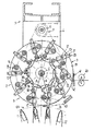
図1〜7において、レスト1は上記スイス国特許第645,074 号の場合と同様にドラム形ギャザリング装置、すなわちギャザリングドラム101 を形成しており、その場合と同様に、ここでもギャザリングドラム101 の回転中に印刷物がレストに載置されて軸方向に搬送され、もちろんそれらが落下しないように保持されている。1973年にウォルター・レイスト(Walter Reist)によって発明されたこの技術は、ドイツ国特許出願第2,447,336 号(米国特許第3,951,399 号に対応)が1975年に公開されて以来、公開従来技術の一部になっているが、また実際に様々な応用分野で採用されており、従って図示の実施例を理解するために丁合いを取る詳細についてはここではこれ以上説明する必要がないであろう。本発明の観点から述べる必要があることは、レストの配置がドラム形でも他の形式でも問題なく、また印刷紙がレスト上にどのように丁合いが取られるか、互いに平行にして長手方向に対して直交する方向に循環させるか、レストへの載置及び完成した印刷物の取り出しをどのように行うかは問題ではない。
【0009】
ギャザリングドラム101 の上方に回転ステープル綴じ装置2があり、これはギャザリングドラム101 と共通の装置フレーム3の2つの側壁4によって懸架されている。これらの側壁4にステープル綴じ装置2の駆動軸5及び副軸6が取り付けられており、これらは側壁4の外側に配置された歯付きベルト駆動部7によって互いに連結されている。
【0010】
ステープル綴じ装置2のステープル綴じヘッドキャリア8がステープル綴じ装置2の駆動軸5に取り付けられており、図示の実施例では、3つの二重壁キャリアディスク9が設けられており、これらは駆動軸に固定されて回転できるようになっており、またこれらの内部にステープル綴じヘッド10が放射状に分散配置されている。特に図6または7と組み合わせて図1を参照すればわかるように、ステープル綴じヘッド10のハウジング11はキャリアディスク9の壁91にピン12で回転可能に取り付けられている。
【0011】
ステープル綴じヘッド10の旋回位置は、ステープル綴じヘッドハウジング11に偏心状に作用するジョイント13によって決定され、ステープル綴じヘッド10のジョイントは他のキャリアディスク9にも同じ「星形アーム」で、すなわち半径Rで取り付けられて、共通のジョイント主軸14で互いに連結されている。特に図7と組み合わせて図1を参照すればわかるように、ジョイント主軸14の端部は、制御ディスク16によって無端閉鎖状制御溝15(図1には示されていない)内を案内され、制御ディスク16は側壁4の内側に当接した状態で位置が固定されているが、回転方向に調節可能であることが好ましい。
【0012】
図1に示されているように、ステープル綴じヘッド10、さらに正確に言えばそれらのステープルガイド17が回転ピン12の半径に対して先行位置でレスト1と出会い、背後位置で前記レストから離れるように構造が段取りされている。言い換えれば、ステープル綴じ領域では、ステープル綴じヘッドの角度位置は対応の半径のそれと一緒に変化するのではなく、ほぼレストのそれと同様に変化するので、レストとステープル綴じヘッドとは1つの回転位置ではなく回転領域で、実際にステープル綴じ領域で互いに理想的に整合する。
【0013】
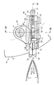
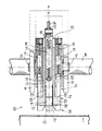
図5〜7に示されているように、各ステープル綴じヘッド10において、ステープルガイド17は、復帰ばね18の作用に逆らうようにステープル綴じヘッドハウジング11内を内向き変位可能に案内され、復帰ばね18はステープル綴じヘッドハウジング11の盲穴19にはめ込まれて、ヘッド20を設けたボルト形カウンターホルダ21によってステープルガイド17の肩部22に支持されている。図6に示されているように、カウンターホルダ21はハウジング11内を案内されて、そのヘッド20が盲穴19にはめ込まれていることによって、ステープルガイド17が誤ってハウジング11から抜け落ちることがないようにしている。ステープルガイド17が作動準備位置にある時、カウンターホルダ21のヘッドはもちろん当接位置にはなく、ばね18の復帰力が完全な効力を生じるようになっている。ステープルガイド17はストップ23(図5)によって復帰力に逆らう位置に保持されており、ストップはハウジングに固定されており、ハウジング11に、さらに正確に言えばハウジングカバー111 に固定された板ばね24の直角に曲がった端部で形成されている。図7に示されているように、カバー111 がU字形断面のハウジング11の開放端部を閉鎖しており、ストップ23はステープル綴じヘッドハウジング内を内向きに変位可能なステープルガイド17の肩部と係合する。
【0014】
ステープルガイド17がこの停止位置にある時、ステープルガイドの、さらに正確に言えばその端部に取り付けられたV字形センタリングアタッチメント25の軌道がレストの循環経路26(例えば図1を参照)と交差することによって、ステープルガイド17がレスト1と出会った時、ステープルガイド17はストップ23から離れて上昇し、ステープル綴じヘッドハウジング11内へ押し戻される。同時に、ステープル綴じヘッド10はレスト1上で正確にセンタリングされ、相対的所望位置からのずれはすべて、レスト1のコンプライアンスによって補償される。反対に、ステープル綴じ位置を離れる時、ステープルガイド17はばね18の復帰力の作用を受けてレスト1に追従し、徐々にレスト1から離れる。ステープル綴じ領域では、センタリングアッタチメントの作用で破損させてはならない丁合取り印刷紙またはそれによって形成された印刷物27がレスト上に載置されていることから、これは重要である。
【0015】
これに関連して、外側キャリアディスク9の左右に二重壁センタリングディスク28が配置されており、これはその壁の間にステープル綴じヘッド10と同じ構造のセンタリングヘッド10’ が支持されている。しかし、これらのセンタリングヘッドは、V字形センタリングアタッチメントでレスト1に直接的に作用するそれの疑似ステープルガイド17’ によってステープル綴じヘッドキャリア8をギャザリング装置に対してセンタリングする機能を持っているだけである。これらの予防手段により、ステープルヘッドキャリアは、ステープル綴じヘッドを交換し、それによって異なった数のステープル綴じ及び/または異なったステープル寸法を必要とする別の印刷物に装置を変更するため、ドラムから離れる位置へ搖動させることができるように固定できることが理解されるであろう。
【0016】
図5〜7に示されているように、カバー111 で閉鎖されているハウジング11のガイドチャネル112 内を変位可能なステープルガイド17も同様に断面がU字形であるため、それらはガイドチャネル112 の底部と協働して、ステープルガイド内に係合しているプッシュロッド29用の内側ガイドを形成している。これらのプッシュロッドには長手方向スロット30が設けられており、それにステープルガイド17のピン31がはまっている。スロット30内に配置されたばね32がピン31上またはプッシュロッド29上に支持されており、プッシュロッド及びステープルガイドを互いに引き離そうとしているが、ピン31がこの傾向に絶対的制限を設定している。この場合、ステープルガイド17及びそれにはまっているプッシュロッド29が、抵抗連結状態でハウジングから引き出すことができる一体状のアセンブリを形成しており、この場合はピン31がスロットの端部に当接しているが、反対方向にはプッシュロッド29またはステープルガイド17が設置状態にあっても互いに変位可能である。
【0017】
しかし、ステープルガイド17が設置状態にある時、プッシュロッド29の休止位置を決定するのは、ピン31ではなく、図5に示されているように、ステープル綴じヘッドハウジング11に形成されたカウンターストップ33と相互作用するプッシュロッド29のストップ292である。このように、ステープルガイド17がレスト1によってステープル綴じ領域内で押し戻された時、対応のプッシュロッド29が静止しているため、ばね32がそれに応じた程度まで緊張することから、抵抗連結が作用し始める。
【0018】
各ステープルガイド17は自由端部に脚部171 で形成されたフォークを設けており、これはそのV字形端面でセンタリングアタッチメント25を形成している。脚部171 の内側壁には、図4のa)に示されているようにU字形ステープル34の脚部を収容するための長手方向のガイド溝172 が形成されている。プッシュロッドリブ291 がこれらのガイド溝に係合して、ステープルガイド17とプッシュロッド29との間に相対移動がある時にステープル34をガイド溝172 から押し出すことができるようになっている。(ここで、ステープル34がどのようにしてそのガイドに到着するかは関係ない。そのような作動については以下に説明する)。
【0019】
各プッシュロッド29はその自由端部に追従ローラ35を支持しており、それは対応のステープル綴じヘッド10(図1及び3)に属する制御リンク36と相互作用する。しかし、特に図1にゆがみ表示で示されているように、ステープル綴じヘッド10が確動制御部13ー14ー15ー16 によってその先行位置から背後位置へ移動するまで、実質的な連結は生じない。図3に示されているように、制御リンク36は、プッシュロッド29を最初はその停止位置から前進させた後、新しい位置に保持するプロフィールを備えている。制御リンク36はピン37でステープル綴じヘッドキャリア8上に回転可能に取り付けられているが、リンクに作用する支持ばね38の力が、制御リンクの退却を防止できる強さを備えている。
【0020】
上記点から、特に図1及び3を参照し、図4に言及しながら次のことが言える。
ステープルガイド17の軌道とレスト1の循環経路26とが交差しているため、レスト1がステープルガイド17と出会った時、ステープルガイド17は上昇してストップ23から離れ、レストによってステープル綴じヘッドハウジング11内へ押し戻され、ステープル綴じヘッドがピン12を中心に回転するため、プッシュロッド29の追従制御部35、36も作動し始める。その結果、図3a)に示されている初期位置から始動して、図4のb)およびc)に示されているようにステープル34がすぐにレスト1上に載置されている印刷物に打ち込まれ( b) )、その後で閉じられるだけとなる( c) )。
【0021】
このため、図4のb)およびc)に示されているように、レスト1内には各ステープル綴じヘッド10用に制御折り曲げ手段39が設けられており、これは対で相互作用して、いずれも共通のプッシュロッド40によって作動される。図4のb)のように印刷物を貫通した後、まだ休止位置にある折り曲げ手段にステープルの脚が当接して、その後の図4のc)のように印刷物の内側に当接する位置への移動に備えて内向きに曲げられる。
【0022】
図4のb)〜c)に従って狭い回転領域で行われるこの閉じ作動中、プッシュロッド29は折り曲げ手段39に対するカウンターホルダとして相互作用する。ストップ23に到達した後、ステープル綴じヘッドは先行位置へ旋回して戻り、その結果として制御カム36がプッシュロッド29をそのストップまで後退させる。同時に、ステープルガイド17は、ステープル綴じヘッドから離れていくレスト1に追従して移動し、そのストップ23に到達しようとする。これにより、ステープル綴じヘッド10は次のステープル34を受け取る準備ができる。
【0023】
ステープル綴じヘッド10にステープル34を供給する方法は、図1及び6を参照すれば容易に想像できるであろう。図1では、ワイヤ前進装置が40で示されており、ワイヤ切断ディスペンサ(詳細には示されていない)のワイヤカッタが41で示されている。例えばヨーロッパ特許公開1,476,718 号に説明されているように、ステープル綴じヘッドがワイヤ切断ディスペンサを通過する時、それからいずれの場合もステープルガイドがワイヤ42(図6)を引き取って、図1では右下の対応のステープル綴じヘッドが位置固定ワイヤ曲げリンク43の領域に進入するまで、例えば磁気的に脚部171 のV字形端部内に保持している。そのリンク43はワイヤ42の中央部分に作用して、それを脚部171 間に押し込むことによって、ワイヤの端部が曲がってガイド溝(図4のa))内へ引き込まれる。これによって、ステープル34が形成される、すなわち次のステープル綴じに備えてステープル綴じヘッド10に装填される。リンク43は、図3に示されているように、ステープル綴じ領域の直前で終了している。
【0024】
【発明の効果】
本発明にかゝるギャザリングステープラによれば、高回転速度においても作動信頼性が向上するだけでなく、様々な品質及び/または長さのワイヤ及びそれに伴った様々なステープル寸法での作動を最小準備作業で実施することができる。
【図面の簡単な説明】
【図1】図2のI−I矢視線に沿う断面図で、回転軸線に垂直な断面の回転式ステープル綴じ装置といくつかの循環レストとを示している。
【図2】回転式ステープル綴じ装置およびレストの1つを一部断面として示す側面図である。
【図3】回転式ステープル綴じ装置のステープル綴じ領域を図1より拡大して示す部分図である。
【図4】ステープル綴じ状態を工程順に示す断面図である。
【図5】図3と同様に単一のステープル綴じヘッドを拡大して示す断面図である。
【図6】図5のVI−VI矢視線に沿う断面図である。
【図7】図5のVII −VII 矢視線に沿っているが、図6の平面に一部重なっている断面図である。
【符号の説明】
1 レスト
2 ステープル綴じ装置
8 ステープル綴じヘッドキャリア
10 ステープル綴じヘッド
17 ステープルガイド
26 レストの循環経路
27 印刷物
29 プッシュロッド
32 復帰ばね[0001]
[Industrial applications]
TECHNICAL FIELD The present invention relates to a gathering stapler for printed matter made of folded printing paper.
[0002]
[Prior art]
Gathering staplers of this type are described in Swiss patent 645,074 and in corresponding U.S. Pat. No. 4,408,755. In any case, such gathering staplers allow collated prints, which are initially combined in the form of a folded web, without the use of conventional opening devices. The printing paper thus or otherwise collated is stapled by the rotary stapling device in the staple area of the circulating rest.
[0003]
By the time the above prior art appeared, the nature and operating principle of the rotary stapling apparatus were well known to those skilled in the art, so the stapling apparatus itself will only be briefly described. That is, it is known that a rotary staple binding head is provided with a push rod which is guided so as to be displaceable substantially in a radial direction for driving staples.
[0004]
[Problems to be solved by the invention]
By the way, in this type of gathering stapler, since the push rod constantly changes its angular position during staple driving, the push rod and the rest and the printed material to be stapled at that time are aligned with each other only by one rotation position. There is a need. However, according to the above-mentioned conventional gathering stapler, there is a problem that the alignment at a high rotation speed is considerably difficult, and the operation at a low rotation speed cannot be avoided in reducing the processing capacity.
[0005]
In light of this background, it is an object of the present invention to provide a gathering stapler of the opening form wherein the staple binding head and the rest are ideally and quickly aligned with each other not only in one rotational position but also in the rotational area. .
[0006]
[Means for Solving the Problems]
In order to achieve the above object, the present invention is a gathering stapler having a gathering section and a rotary stapling apparatus, which is used for printed matter having folded printing paper, wherein the gathering sections extend in parallel with each other. A staple device that circulates in a direction perpendicular to the longitudinal direction, where printing paper is gathered and stapled on a saddle-shaped rest of the gathering portion, and is rotated about an axis (5) ( A plurality of staple binding heads (10) are arranged substantially radially on the carrier (8) of ( 2) , and are driven together with the gathering portion so as to meet each other in the staple binding area. each) is attached to the carrier (8) pivotally to said shaft (5) parallel to the main axis (12) around the respective stapling heads (10), printed matter (27) A staple guide (17) that rides on, and a push rod (29) that is extendably inserted into the staple guide are provided, and a trajectory and a rest at one end of the staple guide (17) are provided. and (1) the circulation path and (26) to be crossed, the stapling device (2) staple guide on the carrier (8) in (17), for that radius (R) in the stapling region Thus, the staple guide (17) can be pivoted from the leading position (a) to the back position (c), and the staple guide (17) is mounted so as to be displaced inwardly against the return force (18) .
[0007]
【Example】
The above and other objects and features of the present invention will become apparent from the following description of the structure and functional principles of embodiments of the present invention with reference to the accompanying drawings.
[0008]
1 to 7, the
[0009]
Above the
[0010]
The staple binding
[0011]
The pivoting position of the
[0012]
As shown in FIG. 1, the
[0013]
As shown in FIGS. 5 to 7, in each
[0014]
When the
[0015]
In this connection, a double-walled centering
[0016]
As shown in FIGS. 5 to 7, the staple guides 17, which are also displaceable in the
[0017]
However, when the
[0018]
Each
[0019]
Each
[0020]
In view of the above, the following can be said with particular reference to FIGS. 1 and 3 and with reference to FIG.
Since the trajectory of the
[0021]
To this end, as shown in FIGS. 4b and c), within the
[0022]
During this closing operation, which takes place in a narrow rotation area according to FIGS. 4 b to 4 c), the
[0023]
The manner in which
[0024]
【The invention's effect】
The gathering stapler according to the present invention not only improves operation reliability even at high rotational speeds, but also minimizes the operation of wires of various qualities and / or lengths and associated staple dimensions. It can be performed in preparation work.
[Brief description of the drawings]
FIG. 1 is a sectional view taken along the line II of FIG. 2, showing a rotary staple binding device having a cross section perpendicular to a rotation axis and some circulation rests;
FIG. 2 is a side view showing a rotary staple binding device and one of the rests as a partial cross section.
FIG. 3 is a partial view showing a staple binding region of the rotary staple binding device in an enlarged manner from FIG. 1;
FIG. 4 is a cross-sectional view showing a staple binding state in the order of steps.
FIG. 5 is an enlarged sectional view showing a single staple binding head as in FIG. 3;
FIG. 6 is a sectional view taken along line VI-VI of FIG. 5;
7 is a sectional view taken along the line VII-VII of FIG. 5, but partially overlapping the plane of FIG. 6;
[Explanation of symbols]
REFERENCE SIGNS
Claims (13)
Applications Claiming Priority (2)
| Application Number | Priority Date | Filing Date | Title |
|---|---|---|---|
| CH00061/93-4 | 1993-01-11 | ||
| CH6193 | 1993-01-11 |
Publications (2)
| Publication Number | Publication Date |
|---|---|
| JPH071859A JPH071859A (en) | 1995-01-06 |
| JP3600988B2 true JP3600988B2 (en) | 2004-12-15 |
Family
ID=4178428
Family Applications (1)
| Application Number | Title | Priority Date | Filing Date |
|---|---|---|---|
| JP35410393A Expired - Fee Related JP3600988B2 (en) | 1993-01-11 | 1993-12-30 | Gathering stapler for printed matter |
Country Status (11)
| Country | Link |
|---|---|
| US (1) | US5464199A (en) |
| EP (1) | EP0606555B1 (en) |
| JP (1) | JP3600988B2 (en) |
| AT (1) | ATE150380T1 (en) |
| AU (1) | AU665880B2 (en) |
| CA (1) | CA2109738C (en) |
| DE (1) | DE59305872D1 (en) |
| DK (1) | DK0606555T3 (en) |
| ES (1) | ES2098633T3 (en) |
| FI (1) | FI108417B (en) |
| RU (1) | RU2106975C1 (en) |
Families Citing this family (21)
| Publication number | Priority date | Publication date | Assignee | Title |
|---|---|---|---|---|
| ATE154919T1 (en) * | 1994-01-10 | 1997-07-15 | Ferag Ag | DEVICE FOR STAPLING PRINTED PRODUCTS |
| EP0691215B1 (en) * | 1994-07-06 | 1997-08-20 | Ferag AG | Device for wire stitching printed products |
| DE19518652C2 (en) * | 1995-05-20 | 1999-08-12 | Koenig & Bauer Ag | Device for stapling signatures |
| EP0827456B1 (en) * | 1995-05-20 | 1999-08-04 | Koenig & Bauer Aktiengesellschaft | Stitching device |
| US5662407A (en) | 1995-09-22 | 1997-09-02 | Lsi Lighting Systems, Inc. | Canopy luminaire |
| CH691058A5 (en) * | 1995-11-01 | 2001-04-12 | Grapha Holding Ag | Device for processing folded printed sheets. |
| EP0981450B1 (en) | 1997-05-07 | 2002-10-23 | Ferag AG | Device for longitudinally stitching multipiece printed products |
| DE50113969D1 (en) * | 2001-03-29 | 2008-06-26 | Grapha Holding Ag | Device for stapling the back with staples, printed products formed from folded printed sheets |
| ATE335697T1 (en) * | 2001-06-28 | 2006-09-15 | Grapha Holding Ag | METHOD FOR PRODUCING A STAPLED PRINTED PRODUCT CONSISTING OF SEVERAL PRINT PRODUCTS AND DEVICE FOR CARRYING OUT THE METHOD. |
| JP3937777B2 (en) * | 2001-09-14 | 2007-06-27 | キヤノン株式会社 | Document processing system, information processing apparatus, setting method thereof, program, and recording medium |
| US7033123B2 (en) * | 2002-02-28 | 2006-04-25 | Hewlett-Packard Development Company, L.P. | Booklet maker |
| US6981830B2 (en) * | 2002-02-28 | 2006-01-03 | Hewlett-Packard Development Company, L.P. | Pivotable collecting device |
| US6962280B2 (en) | 2002-07-05 | 2005-11-08 | Goss International Americas, Inc. | Rotary stitching device |
| US7581724B2 (en) | 2002-11-09 | 2009-09-01 | Ferag Ag | Device for collecting and processing folded printed products |
| ATE409672T1 (en) | 2004-04-22 | 2008-10-15 | Ferag Ag | METHOD AND DEVICE FOR PROCESSING PRINTED PRODUCTS |
| DE102004049488A1 (en) * | 2004-10-11 | 2006-04-13 | Man Roland Druckmaschinen Ag | Stapler of a printing machine |
| CA2629173A1 (en) * | 2005-11-11 | 2007-05-18 | Ferag Ag | Gathering and stitching machine |
| CA2573175A1 (en) | 2006-01-13 | 2007-07-13 | Ferag Ag | Method and installation for processing printed products during conveyance |
| CH699596A1 (en) * | 2008-09-25 | 2010-03-31 | Ferag Ag | Device and method for processing of goods. |
| CN108248242B (en) * | 2018-01-31 | 2019-11-12 | 浙江雅迅眼镜科技有限公司 | A kind of finance voucher finishing binding apparatus |
| CN109702477A (en) * | 2019-01-02 | 2019-05-03 | 得力集团有限公司 | A kind of stapler assembly line |
Family Cites Families (28)
| Publication number | Priority date | Publication date | Assignee | Title |
|---|---|---|---|---|
| US715890A (en) * | 1901-04-08 | 1902-12-16 | Smyth Machine Company | Signature-gatherer. |
| DE1055499B (en) * | 1955-05-02 | 1959-04-23 | Western Printing & Lithographi | Wire stitching machine |
| US2717383A (en) * | 1955-05-02 | 1955-09-13 | Western Printing & Lithographi | Rotary type stitching machine |
| SE353673B (en) * | 1970-04-06 | 1973-02-12 | Tolerans Ab | |
| CH584153A5 (en) * | 1973-10-10 | 1977-01-31 | Ferag Ag | |
| CH575303A5 (en) * | 1975-02-26 | 1976-05-14 | Ferag Ag | |
| CH645074A5 (en) * | 1980-03-11 | 1984-09-14 | Ferag Ag | METHOD AND DEVICE FOR MULTIPLE-LEAF PRINTED PRODUCTS, IN PARTICULAR NEWSPAPERS AND MAGAZINES. |
| CH645073A5 (en) * | 1980-03-11 | 1984-09-14 | Ferag Ag | METHOD AND DEVICE FOR GATHERING LEAVES OR BOW TO MULTI-LEAF PRINTED PRODUCTS, IN PARTICULAR NEWSPAPERS AND MAGAZINES. |
| CH649267A5 (en) * | 1980-11-17 | 1985-05-15 | Ferag Ag | METHOD AND DEVICE FOR INSERTING AT LEAST ONE INSERT IN PRINTED PRODUCTS. |
| CH667621A5 (en) * | 1985-06-04 | 1988-10-31 | Grapha Holding Ag | COLLECTIBLE. |
| IT1185103B (en) * | 1985-06-14 | 1987-11-04 | Cerutti Spa Off Mec | STAPLER PERFECTED FOR SEGANTURE |
| CH667620A5 (en) * | 1985-07-01 | 1988-10-31 | Ferag Ag | METHOD AND DEVICE FOR COLLECTING FOLDED PRINTED SHEETS. |
| CH668245A5 (en) * | 1985-09-27 | 1988-12-15 | Ferag Ag | DEVICE FOR COMPILING DIFFERENT PRINTED PRODUCTS. |
| ATE43123T1 (en) * | 1986-02-14 | 1989-06-15 | Ferag Ag | METHOD AND DEVICE FOR INSTALLING AT LEAST ONE INSERT IN PREFERABLY FOLDED PRINTED PRODUCTS. |
| DE3760149D1 (en) * | 1986-02-14 | 1989-06-15 | Ferag Ag | Apparatus for processing printed products |
| CH679993A5 (en) * | 1987-03-06 | 1992-05-29 | Ferag Ag | |
| US4792077A (en) * | 1987-04-27 | 1988-12-20 | Custom-Bilt Machinery, Inc. | Apparatus for stapling and creasing paper articles in transit |
| CH675873A5 (en) * | 1987-07-02 | 1990-11-15 | Ferag Ag | |
| ATE72555T1 (en) * | 1988-05-11 | 1992-02-15 | Ferag Ag | EQUIPMENT FOR COLLECTING, INSERTING AND COLLECTING PRINTED PRODUCTS. |
| ATE85028T1 (en) * | 1988-05-11 | 1993-02-15 | Ferag Ag | DEVICE FOR COLLECTING FOLDED SHEET. |
| DE58903489D1 (en) * | 1988-05-11 | 1993-03-25 | Ferag Ag | DEVICE FOR PROCESSING PRINTING PRODUCTS. |
| DE58904720D1 (en) * | 1988-11-11 | 1993-07-22 | Ferag Ag | METHOD AND DEVICE FOR CONVEYING PRINTING PRODUCTS. |
| ATE98569T1 (en) * | 1989-05-25 | 1994-01-15 | Ferag Ag | DEVICE FOR COLLECTING AND STAPLING FOLDED SHEET. |
| DE59004157D1 (en) * | 1989-05-25 | 1994-02-17 | Ferag Ag | Device for wire stitching multi-part printed matter. |
| US5137409A (en) * | 1989-07-21 | 1992-08-11 | Ferag Ag | Joining together of printed partial products |
| EP0473902B1 (en) * | 1990-08-06 | 1995-10-11 | Ferag AG | Device for stapling multiple-part printed products |
| CH685045A5 (en) * | 1991-11-07 | 1995-03-15 | Ferag Ag | Apparatus for adhering inserts to printed products. |
| DE59203754D1 (en) * | 1991-12-13 | 1995-10-26 | Ferag Ag | Device for wire stitching multi-part printed matter. |
-
1993
- 1993-11-12 EP EP93118327A patent/EP0606555B1/en not_active Expired - Lifetime
- 1993-11-12 ES ES93118327T patent/ES2098633T3/en not_active Expired - Lifetime
- 1993-11-12 DK DK93118327.1T patent/DK0606555T3/en active
- 1993-11-12 AT AT93118327T patent/ATE150380T1/en active
- 1993-11-12 DE DE59305872T patent/DE59305872D1/en not_active Expired - Lifetime
- 1993-11-23 CA CA002109738A patent/CA2109738C/en not_active Expired - Fee Related
- 1993-12-20 AU AU52570/93A patent/AU665880B2/en not_active Expired
- 1993-12-23 US US08/172,649 patent/US5464199A/en not_active Expired - Lifetime
- 1993-12-23 RU RU93056601A patent/RU2106975C1/en not_active IP Right Cessation
- 1993-12-30 JP JP35410393A patent/JP3600988B2/en not_active Expired - Fee Related
-
1994
- 1994-01-10 FI FI940094A patent/FI108417B/en not_active IP Right Cessation
Also Published As
| Publication number | Publication date |
|---|---|
| AU665880B2 (en) | 1996-01-18 |
| ATE150380T1 (en) | 1997-04-15 |
| DE59305872D1 (en) | 1997-04-24 |
| CA2109738A1 (en) | 1994-07-12 |
| AU5257093A (en) | 1994-07-14 |
| FI940094A (en) | 1994-07-12 |
| JPH071859A (en) | 1995-01-06 |
| FI940094A0 (en) | 1994-01-10 |
| DK0606555T3 (en) | 1997-10-13 |
| CA2109738C (en) | 2006-01-03 |
| EP0606555A1 (en) | 1994-07-20 |
| ES2098633T3 (en) | 1997-05-01 |
| FI108417B (en) | 2002-01-31 |
| EP0606555B1 (en) | 1997-03-19 |
| US5464199A (en) | 1995-11-07 |
| RU2106975C1 (en) | 1998-03-20 |
Similar Documents
| Publication | Publication Date | Title |
|---|---|---|
| JP3600988B2 (en) | Gathering stapler for printed matter | |
| RU2070518C1 (en) | Device for stitching printed matter consisting of several parts with wire | |
| JPS5839748B2 (en) | Printed product handling equipment | |
| JPH0739308B2 (en) | Automatic collator | |
| RU2057029C1 (en) | Device for assembling folded printer's sheets | |
| JP3277252B2 (en) | Binding machine | |
| HU227929B1 (en) | Needling loom feeding with continuous helical strip | |
| JP2006069763A (en) | Sheet folding device | |
| EP1242235B1 (en) | Separator finger apparatus | |
| US2717383A (en) | Rotary type stitching machine | |
| US4717136A (en) | Process and apparatus for feeding in of recording carriers to the writing roller of an office machine | |
| US4627754A (en) | Drum clamping mechanism for a printer | |
| US6223964B1 (en) | Device for longitudinally stitching multipiece printed products | |
| RU99125608A (en) | DEVICE FOR STAPLING IN LONGITUDINAL DIRECTION CONSISTING OF MANY PARTS OF TYPOGRAPHIC PRODUCTS | |
| JPH0343076B2 (en) | ||
| JPS60244758A (en) | Folding device | |
| US5690265A (en) | Stapling device | |
| US3040324A (en) | High speed stitcher | |
| JP4646481B2 (en) | Device for stapling the back of printed matter formed from folded printed paper leaves | |
| JP4748293B2 (en) | Built-in stapler | |
| JP5867183B2 (en) | Paper processing apparatus, image forming system having the same, and paper folding method | |
| AU676215B2 (en) | Buckle folding machine | |
| US2104452A (en) | Sheet cutting, stitching, and folding mechanism | |
| JPH10218477A (en) | Sheet after-treatment device | |
| JPH06278913A (en) | Needle clamping sorter with jogger |
Legal Events
| Date | Code | Title | Description |
|---|---|---|---|
| A601 | Written request for extension of time |
Free format text: JAPANESE INTERMEDIATE CODE: A601 Effective date: 20040108 |
|
| A602 | Written permission of extension of time |
Free format text: JAPANESE INTERMEDIATE CODE: A602 Effective date: 20040115 |
|
| A521 | Request for written amendment filed |
Free format text: JAPANESE INTERMEDIATE CODE: A523 Effective date: 20040407 |
|
| TRDD | Decision of grant or rejection written | ||
| A01 | Written decision to grant a patent or to grant a registration (utility model) |
Free format text: JAPANESE INTERMEDIATE CODE: A01 Effective date: 20040818 |
|
| A61 | First payment of annual fees (during grant procedure) |
Free format text: JAPANESE INTERMEDIATE CODE: A61 Effective date: 20040909 |
|
| R150 | Certificate of patent or registration of utility model |
Free format text: JAPANESE INTERMEDIATE CODE: R150 |
|
| FPAY | Renewal fee payment (event date is renewal date of database) |
Free format text: PAYMENT UNTIL: 20071001 Year of fee payment: 3 |
|
| FPAY | Renewal fee payment (event date is renewal date of database) |
Free format text: PAYMENT UNTIL: 20081001 Year of fee payment: 4 |
|
| FPAY | Renewal fee payment (event date is renewal date of database) |
Free format text: PAYMENT UNTIL: 20091001 Year of fee payment: 5 |
|
| FPAY | Renewal fee payment (event date is renewal date of database) |
Free format text: PAYMENT UNTIL: 20101001 Year of fee payment: 6 |
|
| FPAY | Renewal fee payment (event date is renewal date of database) |
Free format text: PAYMENT UNTIL: 20101001 Year of fee payment: 6 |
|
| FPAY | Renewal fee payment (event date is renewal date of database) |
Free format text: PAYMENT UNTIL: 20111001 Year of fee payment: 7 |
|
| LAPS | Cancellation because of no payment of annual fees |