JP4748293B2 - Built-in stapler - Google Patents
Built-in stapler Download PDFInfo
- Publication number
- JP4748293B2 JP4748293B2 JP2001275405A JP2001275405A JP4748293B2 JP 4748293 B2 JP4748293 B2 JP 4748293B2 JP 2001275405 A JP2001275405 A JP 2001275405A JP 2001275405 A JP2001275405 A JP 2001275405A JP 4748293 B2 JP4748293 B2 JP 4748293B2
- Authority
- JP
- Japan
- Prior art keywords
- unit
- clincher
- driver
- staple
- driver unit
- Prior art date
- Legal status (The legal status is an assumption and is not a legal conclusion. Google has not performed a legal analysis and makes no representation as to the accuracy of the status listed.)
- Expired - Fee Related
Links
Images


Classifications
-
- B—PERFORMING OPERATIONS; TRANSPORTING
- B27—WORKING OR PRESERVING WOOD OR SIMILAR MATERIAL; NAILING OR STAPLING MACHINES IN GENERAL
- B27F—DOVETAILED WORK; TENONS; SLOTTING MACHINES FOR WOOD OR SIMILAR MATERIAL; NAILING OR STAPLING MACHINES
- B27F7/00—Nailing or stapling; Nailed or stapled work
- B27F7/17—Stapling machines
- B27F7/19—Stapling machines with provision for bending the ends of the staples on to the work
-
- B—PERFORMING OPERATIONS; TRANSPORTING
- B27—WORKING OR PRESERVING WOOD OR SIMILAR MATERIAL; NAILING OR STAPLING MACHINES IN GENERAL
- B27F—DOVETAILED WORK; TENONS; SLOTTING MACHINES FOR WOOD OR SIMILAR MATERIAL; NAILING OR STAPLING MACHINES
- B27F7/00—Nailing or stapling; Nailed or stapled work
- B27F7/17—Stapling machines
Landscapes
- Engineering & Computer Science (AREA)
- Mechanical Engineering (AREA)
- Life Sciences & Earth Sciences (AREA)
- Forests & Forestry (AREA)
- Portable Nailing Machines And Staplers (AREA)
- Dovetailed Work, And Nailing Machines And Stapling Machines For Wood (AREA)
Description
【0001】
【発明の属する技術分野】
本発明は、コピー機やファクシミリ機等の機器に内蔵されて、コピー用紙やファクシミリ受信した用紙を所定枚数毎に綴じ合わせする機器内蔵型の電動ホッチキスに関する。
【従来の技術】
【0002】
コピー機やファクシミリ機等の事務機器において、これらの機器でコピーやファクシミリ受信等の処理が行われた用紙を所定の枚数毎に自動的に綴じ合わせするために、電動モータ等で駆動されるホッチキスを内蔵した機器が知られている。通常の机上等で使用されるホッチキスでは、マガジン部に装填されたステープルを綴じ用紙に向けて順次打ち出すようにしたマガジン部に対して、綴じ用紙を貫通したステープルの脚先端を折り曲げるクリンチャ部とが一端部で互いに枢着支持されて構成されているものであるが、上記のような事務機器に内蔵されているホッチキスでは、モータによりドライバを駆動してマガジン部に装填されたステープルを綴じ用紙に向けて順次打ち出すようにしたドライバユニットと、綴じ用紙を貫通したステープルの脚先端を綴じ用紙の背面に沿って折り曲げるクリンチャユニットとが独立して構成されており、両ユニットが所定の間隔を隔てて機器のフレームに各々が独立して移動可能に支持されている。綴じ用紙は両ユニットの間に供給されて、両ユニットを同期させて移動・駆動させることにより綴じ用紙の任意の箇所へステープル止めが行われる。このように構成することにより、ドライバユニットとクリンチャユニットの間に両ユニットを枢着支持する機構を必要としないので、コピー機等で処理される用紙を両ユニットの間で供給・排出方向を自由に設計できるため、例えば用紙を一定方向に供給排出させるようにする等で機器の設計が容易であり、また処理速度の向上が図れるというメリットがある。
【0003】
【発明が解決しようとする課題】
ところで、上記の機器内蔵型のホッチキスにおいては、ドライバユニットのマガジン部へのステープルの補充を行う必要があり、また、ドライバによってドライバユニットのマガジン先端部に形成されている打出通路から打ち出されるステープルの脚が、綴じ用紙を貫通できず座屈してしまい前記打出通路内に詰まってしまうことが希に発生する。これらの場合には、ドライバユニットをホームポジションへ移動させてドライバユニットのマガジン部へステープルを補充する作業を行ったり、また、ドライバユニットのマガジン先端部に形成されている打出通路内から詰まったステープルを除去する作業が必要となる場合がある。
【0004】
従来の機構では、綴じ用紙の任意の箇所にステープル止めを行うためドライバユニットとクリンチャユニットとは上下に整合した状態で同期して移動できるように支持されており、両ユニットの位置の位置を一致させるために両ユニットの移動範囲の一端側にホームポジションが設定されており、両ユニットをホームポジションに移動させた状態でステープルの装填やジャムステープルの除去作業を行うようにしている。しかしながら、上記両ユニットのホームポジションは同じ位置に設定されているため、両ユニットがホームポジションに移動された状態では、ドライバユニットのマガジン部の上方にクリンチャユニットが位置しているため、ドライバユニットのマガジン部に対してのステープルの装填やジャムステープルの除去作業がやりづらいという問題があった。
【0005】
本発明は、ドライバユニットとクリンチャユニットとを独立させて移動可能に支持させたホッチキスでの、ドライバユニットのマガジン部へのステープル補充のための作業や、マガジン先端部の打出通路内で詰まってしまったジャムステープルの除去の作業を容易に行うことが可能な機器内蔵型のホッチキスを提供することを課題とするものである。
【0006】
【課題を解決するための手段】
上記課題を解決するため本発明は、モータ駆動されるドライバによってマガジン部に装填されたステープルを綴じ用紙に向けて打ち出すドライバユニットと、綴じ用紙を貫通したステープルの脚を綴じ用紙の裏面に沿って折り曲げるクリンチャユニットとを独立させて構成するとともに、各ユニットを所定間隔を隔ててそれぞれを移動可能に支持させた機器内蔵型のホッチキスにおいて、各ユニットの移動範囲の一方の端部における停止位置をずらして設定するとともに、前記一方のユニットの停止位置を前記他方のユニットの停止位置よりも移動範囲の内側に設定したことを特徴とするものである。
【0007】
【発明の実施の形態】
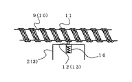
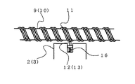
以下、本発明の実施の形態を図に示す実施例に基づいて説明する。図1はコピー機、印刷機又はファクシミリ等の事務機器の内部に組み込まれて、コピー、印刷又はファックス受信した所定枚数の用紙を自動的に綴じ合わせる電動ホッチキスを示す。電動ホッチキス1は、多数のステープルが装填されたマガジン部、該マガジン内のステープルを綴じ用紙に向けて打ち出すドライバプレート及び前記ドライバプレートを駆動する駆動機構から構成されているドライバユニット2と、綴じ用紙を貫通したステープルの脚を綴じ用紙の裏面に沿って折り曲げる可動クリンチャ機構とこれを駆動する駆動機構から構成されているクリンチャユニット3とからなっている。両ユニット2、3にはそれぞれガイドスリーブ4、5が一体に形成されており、該ガイドスリーブ4、5を介して事務機器内に形成されている両側のフレーム6間に架設されているガイドロッド7、8に摺動自在に支持されている。
【0008】
ドライバユニット2とクリンチャユニット3を摺動自在にガイドしているガイドロッド7、8と平行に各ユニット2、3を各々ガイドロッド7、8に沿って移動させるための駆動シャフト9、10が両側のフレーム6間に配置されており、該駆動シャフト9、10の外周面には同一ピッチの螺旋溝11が形成されている。図3及び図4に示すように、ドライバユニット2及び各クリンチャユニット3には各々の駆動シャフト9、10に向けて突出された係合片12、13がそれぞれ設けられており、該係合片12、13が駆動シャフト9、10の前記螺旋溝11と係合されることにより、駆動シャフト9、10の回転に伴って各ユニット2、3がガイドロッド7、8に沿って移動され、綴じ用紙の任意の位置にステープル止めを行う。
【0009】
ドライバユニット2とクリンチャユニット3を移動させるための各々の駆動シャフト9、10の回転方向及び回転速度は互いに同期されており、ドライバユニット2とクリンチャユニット3は上下方向に整合した状態でガイドロッド7、8上を同じ方向へ移動される。これにより、ドライバユニット2から打ち出されるステープルの位置とクリンチャユニット3の位置がずれることなく移動した任意の位置でステープル止めが確実に行える。駆動シャフト9、10の外周面に形成されている螺旋溝11の断面は駆動シャフトの回転を各ユニット2、3の移動方向に確実に伝えるため図5に示すように溝の底部が狭くなるようにほぼ台形に形成されている。
【0010】
ドライバユニット2とクリンチャユニット3は、コピー等の処理された綴じ用紙を通過させる用紙通路14を挟んで上下方向に間隔を隔てて対峙して配置されており、両ユニット2、3間に形成された用紙通路14に供給された綴じ用紙の所定位置にステープル止めを行うように各々が駆動される。なお、両ユニット2、3をステープル止め位置へ移動させる制御や、ドライバユニット2とクリンチャユニット3をそれぞれ駆動して綴じ用紙へのステープル止めを行わせる駆動制御はコピー機等の事務機器側に設けた制御装置により、コピー等の処理及び用紙の給排処理の制御とともに行われる。
【0011】
クリンチャユニット3の移動範囲の一側にはクリンチャユニット3の一側への移動範囲を規制するためのストッパ15が形成されており、このストッパ15の端部がクリンチャユニット3のガイドスリーブ5の端部と当接することによりクリンチャユニット3の移動が阻止されて停止させられる。ドライバユニット2の移動範囲の一側にはストッパが形成されておらず、従ってドライバユニット2は図2に示すようにクリンチャユニット3の停止位置よりも更に一側方向に移動が可能となっている。
【0012】
図3及び図4に示すように、駆動シャフト9、10の螺旋溝11と係合するドライバユニット2とクリンチャユニット3に設けられている各々の係合片12、13は、各ユニット2、3から駆動シャフト9、10に向けて突出するようにバネ16による付勢力が作用されており、このバネ16の作用により先端部が螺旋溝11内に収容されるように係合されている。ドライバユニット2のマガジン内のステープルが無くなったとき又は、マガジン先端部のステープルの打出通路内でステープルがジャムして詰まった場合には、前記制御装置を介してステープルの装填又はジャムステープル除去の作業を行うように指示が行われる。これらの作業の制御が作動すると駆動シャフト9、10が回転駆動されてドライバユニット2とクリンチャユニット3が上下に整合した状態で一側方向に移動される。クリンチャユニット3が前記ストッパ15により停止されたとき、駆動シャフト10の更なる回転に伴ってクリンチャユニット3側の係合片13はバネ16の付勢力に抗してクリンチャユニット3側に退避動して螺旋溝11から外れる。このとき、螺旋溝11の断面は前記のように台形である為、係合片13は容易に螺旋溝から離れることができる。ドライバユニット2にはストッパが形成されていないので、駆動シャフト9の回転により更に一側方向に移動して移動範囲の端部で停止される。
【0013】
従って、ステープルの装填やジャムステープル除去の作業を行うため、ドライバユニット2とクリンチャユニット3とを一側に移動させた状態では、ドライバユニット2とクリンチャユニット3の上下の整合状態が解消し、ドライバユニット2がクリンチャユニット3よりも更に一側方向に移動するので、ドライバユニット2の上面側に空間が形成されて、ドライバユニット2のマガジン部へのステープルの補充のための操作及び、ドライバユニット2のマガジン前端部のステープル通路内のジャムステープルの除去作業が楽に行えるようになる。
【0014】
ドライバユニット2のマガジン部へのステープルの装填作業や、マガジン先端部からのジャムステープルの除去の作業が終了した後は、駆動シャフト9、10を逆方向に回転駆動して両ユニット2、3を反対側の端部まで駆動させて、クリンチャユニット3の係止片13が駆動シャフト10の螺旋溝11の所定の位置に再度係合するように操作する。このとき、クリンチャユニット3は係合片13が駆動シャフト10の螺旋溝11の任意位置に係合してドライバユニット2より先行して他側方向に移動し、他方の端部に形成されているホームポジション位置で停止されて係合片13が螺旋溝11から外れる。駆動シャフト9、10が更に回転することによりドライバユニット2がホームポジション位置まで移動されて、この時点でクリンチャユニット3の係合片13が駆動シャフト10の元の螺旋溝11位置と係合して、これによりドライバユニット2とクリンチャユニット3とは上下方向に整合した状態で一緒に移動できるようになり、任意の位置に移動してステープル止めを行うことができる。また、ドライバユニット2をストッパで停止させ、クリンチャユニット3が更に一側方向に進むことができる構成にしてもよい。
【0015】
【発明の効果】
以上のように本発明によれば、ステープルの装填やジャムステープル除去のための作業の対象となるドライバユニット2の停止位置を、それの上方に配置されるクリンチャユニット3の停止位置よりも移動範囲の内側に移動できるように設定しているので、これらの作業時にはドライバユニット2のマガジン部の上部に大きな空間を形成させることができ、ステープルの装填作業や、ジャムステープルの除去作業が、クリンチャユニット3により邪魔されること無く、容易に行うことが可能となる。
【図面の簡単な説明】
【図1】機器内蔵型のホッチキスの通常のステープル止め駆動時の正面図
【図2】ステープル装填作業のために移動した状態の図1と同じ正面図
【図3】図1と同じ状態のクリンチャユニットの係合片と駆動シャフトの関係を示す正面図
【図4】図2と同じ状態のクリンチャユニットの係合片と駆動シャフトの関係を示す正面図
【図5】駆動シャフトと係合片の構造を示す拡大断面図
【符号の説明】
1 電動ホッチキス
2 ドライバユニット
3 クリンチャユニット
4 ガイドスリーブ
5 ガイドスリーブ
6 フレーム
7 ガイドロッド
8 ガイドロッド
9 駆動シャフト
10 駆動シャフト
11 螺旋溝
12 係合片
13 係合片
14 用紙通路
15 ストッパ
16 バネ[0001]
BACKGROUND OF THE INVENTION
The present invention relates to an electric stapler with a built-in device, which is incorporated in a device such as a copying machine or a facsimile machine, and binds copy paper or facsimile received paper every predetermined number.
[Prior art]
[0002]
Staplers driven by an electric motor or the like in an office machine such as a copying machine or a facsimile machine in order to automatically bind the sheets that have been subjected to processing such as copying or facsimile reception by a predetermined number of sheets. Devices with built-in are known. In a stapler used on a normal desk or the like, there is a clincher section that bends the leg ends of staples that penetrate the binding paper, with respect to the magazine section in which the staples loaded in the magazine section are sequentially ejected toward the binding paper. In the stapler built in the office equipment as described above, the staples loaded in the magazine unit are driven onto the binding paper by driving the driver with a motor. The driver unit is designed to be ejected sequentially, and the clincher unit that bends the tip end of the staple penetrating the binding paper along the back surface of the binding paper, and the two units are spaced apart from each other at a predetermined interval. Each is supported by the frame of the device so as to be independently movable. The binding sheets are supplied between both units, and are stapled to an arbitrary portion of the binding sheets by moving and driving both units in synchronization. With this configuration, there is no need for a mechanism for pivotally supporting both units between the driver unit and the clincher unit, so that paper processed by a copier or the like can be freely supplied and discharged between the units. Therefore, there is an advantage that the device can be easily designed and the processing speed can be improved by, for example, supplying and discharging paper in a certain direction.
[0003]
[Problems to be solved by the invention]
By the way, in the above-mentioned stapler with a built-in device, it is necessary to replenish staples to the magazine portion of the driver unit, and staples that are driven out from the discharge passage formed at the tip of the magazine of the driver unit by the driver. In rare cases, the leg buckles without being able to penetrate the binding paper and is clogged in the launch path. In these cases, the driver unit is moved to the home position to replenish staples in the magazine of the driver unit, or staples jammed from the inside of the ejection path formed at the magazine tip of the driver unit. It may be necessary to remove the material.
[0004]
In the conventional mechanism, the driver unit and the clincher unit are supported so that they can be moved synchronously in a state where they are aligned vertically in order to perform stapling on an arbitrary portion of the binding paper, and the positions of both units coincide with each other. For this purpose, a home position is set at one end of the movement range of both units, and staple loading and jamming staple removal operations are performed with both units moved to the home position. However, since the home position of both units is set to the same position, when both units are moved to the home position, the clincher unit is located above the magazine portion of the driver unit. There is a problem that it is difficult to load staples and remove jammed staples in the magazine section.
[0005]
According to the present invention, the staple unit in which the driver unit and the clincher unit are independently supported so as to be movable is clogged in the operation for replenishing staples to the magazine portion of the driver unit or in the ejection passage at the front end portion of the magazine. It is an object of the present invention to provide a device built-in type stapler capable of easily removing jammed staples.
[0006]
[Means for Solving the Problems]
In order to solve the above-described problems, the present invention provides a driver unit that drives a staple loaded in a magazine portion toward a binding sheet by a motor-driven driver, and a staple leg penetrating the binding sheet along the back surface of the binding sheet. In the stapler with built-in equipment, in which each unit is movably supported at a predetermined interval, the stop position at one end of the moving range of each unit is shifted. And the stop position of the one unit is set to the inside of the moving range from the stop position of the other unit.
[0007]
DETAILED DESCRIPTION OF THE INVENTION
Hereinafter, embodiments of the present invention will be described based on examples shown in the drawings. FIG. 1 shows an electric stapler incorporated in an office machine such as a copying machine, a printing machine, or a facsimile machine, and automatically binds a predetermined number of sheets received by copying, printing or faxing. The
[0008]
[0009]
The rotational directions and rotational speeds of the
[0010]
The
[0011]
A
[0012]
As shown in FIGS. 3 and 4, the
[0013]
Therefore, when the
[0014]
After the operation of loading the staples into the magazine portion of the
[0015]
【The invention's effect】
As described above, according to the present invention, the stop position of the
[Brief description of the drawings]
FIG. 1 is a front view of a built-in type stapler during normal stapling driving. FIG. 2 is a front view same as FIG. 1 in a state of being moved for a staple loading operation. FIG. 3 is a clincher in the same state as FIG. FIG. 4 is a front view showing the relationship between the engagement piece of the unit and the drive shaft. FIG. 4 is a front view showing the relationship between the engagement piece of the clincher unit and the drive shaft in the same state as FIG. Expanded sectional view showing the structure 【Explanation of symbols】
DESCRIPTION OF
Claims (1)
Priority Applications (8)
| Application Number | Priority Date | Filing Date | Title |
|---|---|---|---|
| JP2001275405A JP4748293B2 (en) | 2001-09-11 | 2001-09-11 | Built-in stapler |
| CNB028176103A CN100376371C (en) | 2001-09-11 | 2002-09-10 | Built-in equipment type stapler |
| DE60233510T DE60233510D1 (en) | 2001-09-11 | 2002-09-10 | STAPLER WITH MOUNTING EQUIPMENT |
| PCT/JP2002/009229 WO2003022539A1 (en) | 2001-09-11 | 2002-09-10 | Built-in equipment type stapler |
| KR1020047003537A KR100662925B1 (en) | 2001-09-11 | 2002-09-10 | Built-in equipment type stapler |
| EP02765475A EP1426154B1 (en) | 2001-09-11 | 2002-09-10 | Built-in equipment type stapler |
| US10/488,989 US6974066B2 (en) | 2001-09-11 | 2002-09-10 | Built-in equipment type stapler |
| TW091120717A TW564213B (en) | 2001-09-11 | 2002-09-11 | Built-in equipment type |
Applications Claiming Priority (1)
| Application Number | Priority Date | Filing Date | Title |
|---|---|---|---|
| JP2001275405A JP4748293B2 (en) | 2001-09-11 | 2001-09-11 | Built-in stapler |
Publications (2)
| Publication Number | Publication Date |
|---|---|
| JP2005231036A JP2005231036A (en) | 2005-09-02 |
| JP4748293B2 true JP4748293B2 (en) | 2011-08-17 |
Family
ID=19100273
Family Applications (1)
| Application Number | Title | Priority Date | Filing Date |
|---|---|---|---|
| JP2001275405A Expired - Fee Related JP4748293B2 (en) | 2001-09-11 | 2001-09-11 | Built-in stapler |
Country Status (8)
| Country | Link |
|---|---|
| US (1) | US6974066B2 (en) |
| EP (1) | EP1426154B1 (en) |
| JP (1) | JP4748293B2 (en) |
| KR (1) | KR100662925B1 (en) |
| CN (1) | CN100376371C (en) |
| DE (1) | DE60233510D1 (en) |
| TW (1) | TW564213B (en) |
| WO (1) | WO2003022539A1 (en) |
Families Citing this family (4)
| Publication number | Priority date | Publication date | Assignee | Title |
|---|---|---|---|---|
| US7902257B2 (en) * | 2002-04-01 | 2011-03-08 | University Of Southern California | Trihydroxy polyunsaturated eicosanoid |
| JP4110855B2 (en) * | 2002-06-28 | 2008-07-02 | マックス株式会社 | Electric stapler moving mechanism |
| DE502004009572D1 (en) * | 2004-08-24 | 2009-07-16 | Mueller Martini Holding Ag | Method for stapling printed products and stapling machine |
| JP2011131444A (en) * | 2009-12-23 | 2011-07-07 | Max Co Ltd | Stapler for saddle stitching |
Family Cites Families (14)
| Publication number | Priority date | Publication date | Assignee | Title |
|---|---|---|---|---|
| US4444491A (en) * | 1980-08-21 | 1984-04-24 | Xerox Corporation | Very high speed duplicator with finishing function |
| DE3743979C1 (en) * | 1987-12-23 | 1989-06-15 | Offermann Zeiler Schmid Bwf | Method and device for the automatic de-needling and needling of needle boards |
| JP3020970B2 (en) * | 1989-01-18 | 2000-03-15 | 株式会社リコー | Paper processing equipment |
| US5029831A (en) * | 1989-11-14 | 1991-07-09 | Xerox Corporation | Stapler indexing apparatus |
| JP2816413B2 (en) * | 1990-06-16 | 1998-10-27 | ニスカ株式会社 | Sorter with step ring mechanism |
| DE4035869A1 (en) * | 1990-11-10 | 1992-05-14 | Kodak Ag | STAPLE FOR STAPLING LEAFS |
| DE69313999T2 (en) * | 1992-12-29 | 1998-01-29 | Max Co Ltd | Precision stapler |
| JPH08108377A (en) * | 1994-08-08 | 1996-04-30 | Nisca Corp | Stapler and bookbinding device using it |
| JP3247598B2 (en) * | 1995-11-10 | 2002-01-15 | 株式会社荏原製作所 | Granular phosphorus adsorbent and method for removing phosphorus |
| JP3473234B2 (en) * | 1995-11-16 | 2003-12-02 | ニスカ株式会社 | Stapler |
| JP3473233B2 (en) * | 1995-11-16 | 2003-12-02 | ニスカ株式会社 | Stapler |
| DE59807190D1 (en) * | 1998-05-18 | 2003-03-20 | Grapha Holding Ag | Wire stitching machine for a saddle stitcher with a saddle chain. |
| JP2000084903A (en) * | 1998-09-11 | 2000-03-28 | Minolta Co Ltd | Stapling device |
| US6641024B2 (en) * | 2000-02-08 | 2003-11-04 | Nisca Corporation | Stapling device |
-
2001
- 2001-09-11 JP JP2001275405A patent/JP4748293B2/en not_active Expired - Fee Related
-
2002
- 2002-09-10 CN CNB028176103A patent/CN100376371C/en not_active Expired - Fee Related
- 2002-09-10 KR KR1020047003537A patent/KR100662925B1/en not_active IP Right Cessation
- 2002-09-10 WO PCT/JP2002/009229 patent/WO2003022539A1/en active Application Filing
- 2002-09-10 EP EP02765475A patent/EP1426154B1/en not_active Expired - Lifetime
- 2002-09-10 DE DE60233510T patent/DE60233510D1/en not_active Expired - Lifetime
- 2002-09-10 US US10/488,989 patent/US6974066B2/en not_active Expired - Lifetime
- 2002-09-11 TW TW091120717A patent/TW564213B/en not_active IP Right Cessation
Also Published As
| Publication number | Publication date |
|---|---|
| KR20040034724A (en) | 2004-04-28 |
| US20040238589A1 (en) | 2004-12-02 |
| CN1553849A (en) | 2004-12-08 |
| TW564213B (en) | 2003-12-01 |
| EP1426154A8 (en) | 2004-09-15 |
| DE60233510D1 (en) | 2009-10-08 |
| US6974066B2 (en) | 2005-12-13 |
| EP1426154B1 (en) | 2009-08-26 |
| EP1426154A4 (en) | 2007-09-26 |
| KR100662925B1 (en) | 2006-12-28 |
| EP1426154A1 (en) | 2004-06-09 |
| JP2005231036A (en) | 2005-09-02 |
| WO2003022539A1 (en) | 2003-03-20 |
| CN100376371C (en) | 2008-03-26 |
Similar Documents
| Publication | Publication Date | Title |
|---|---|---|
| US5791548A (en) | Motor driven stapler | |
| JP4389391B2 (en) | Document binding device | |
| JP3679702B2 (en) | Sheet post-processing apparatus and image forming apparatus provided with sheet post-processing apparatus | |
| JP4748293B2 (en) | Built-in stapler | |
| JP4239732B2 (en) | Electric stapler drive mechanism | |
| US11112744B2 (en) | Post-processing device and image forming apparatus | |
| JP4073505B2 (en) | Paper post-processing device | |
| JPH11301919A (en) | Paper sheet post-processing device | |
| JP4071708B2 (en) | Paper processing apparatus and image forming system | |
| JP4103710B2 (en) | Electric stapler staple supply mechanism | |
| JP4184639B2 (en) | Paper processing device | |
| KR0161245B1 (en) | Stapling device of stapler sorter | |
| JP2005081520A (en) | Stapler forming and driving mechanism | |
| JP4366869B2 (en) | Document binding device | |
| JP4044461B2 (en) | Paper processing apparatus and image forming system | |
| JP2004018173A (en) | Binding device | |
| JP2004018172A (en) | Binding device | |
| JPH02297493A (en) | Paper treating device | |
| JP2000128420A (en) | Paper treating device | |
| JPH0663343U (en) | Staple feeder for electric stapler | |
| JP5577883B2 (en) | Post-processing apparatus, image forming apparatus, and post-processing program | |
| JP2004277094A (en) | Sheet handling device | |
| JPH1045317A (en) | Sheet post-processing device for image forming device | |
| JP2004277141A (en) | Sheet handling device | |
| JPH09309662A (en) | Sheet post-processor for image forming apparatus |
Legal Events
| Date | Code | Title | Description |
|---|---|---|---|
| A621 | Written request for application examination |
Free format text: JAPANESE INTERMEDIATE CODE: A621 Effective date: 20080625 |
|
| TRDD | Decision of grant or rejection written | ||
| A01 | Written decision to grant a patent or to grant a registration (utility model) |
Free format text: JAPANESE INTERMEDIATE CODE: A01 Effective date: 20110420 |
|
| A61 | First payment of annual fees (during grant procedure) |
Free format text: JAPANESE INTERMEDIATE CODE: A61 Effective date: 20110503 |
|
| R150 | Certificate of patent or registration of utility model |
Ref document number: 4748293 Country of ref document: JP Free format text: JAPANESE INTERMEDIATE CODE: R150 Free format text: JAPANESE INTERMEDIATE CODE: R150 |
|
| FPAY | Renewal fee payment (event date is renewal date of database) |
Free format text: PAYMENT UNTIL: 20140527 Year of fee payment: 3 |
|
| LAPS | Cancellation because of no payment of annual fees |