JP3598604B2 - Heat transfer device - Google Patents
Heat transfer device Download PDFInfo
- Publication number
- JP3598604B2 JP3598604B2 JP23117495A JP23117495A JP3598604B2 JP 3598604 B2 JP3598604 B2 JP 3598604B2 JP 23117495 A JP23117495 A JP 23117495A JP 23117495 A JP23117495 A JP 23117495A JP 3598604 B2 JP3598604 B2 JP 3598604B2
- Authority
- JP
- Japan
- Prior art keywords
- refrigerant
- heat source
- liquid
- heat
- source means
- Prior art date
- Legal status (The legal status is an assumption and is not a legal conclusion. Google has not performed a legal analysis and makes no representation as to the accuracy of the status listed.)
- Expired - Fee Related
Links
- 239000003507 refrigerant Substances 0.000 claims description 1602
- 239000007788 liquid Substances 0.000 claims description 1449
- 238000010438 heat treatment Methods 0.000 claims description 255
- 238000001816 cooling Methods 0.000 claims description 200
- 230000005855 radiation Effects 0.000 claims description 158
- 238000010521 absorption reaction Methods 0.000 claims description 136
- 230000017525 heat dissipation Effects 0.000 claims description 127
- 230000005494 condensation Effects 0.000 claims description 78
- 238000009833 condensation Methods 0.000 claims description 78
- 230000007246 mechanism Effects 0.000 claims description 35
- 238000010257 thawing Methods 0.000 claims description 32
- 238000001704 evaporation Methods 0.000 claims description 23
- 230000015572 biosynthetic process Effects 0.000 claims description 8
- 230000008020 evaporation Effects 0.000 claims description 8
- 230000008859 change Effects 0.000 claims description 2
- 238000000034 method Methods 0.000 claims 2
- 238000011084 recovery Methods 0.000 description 43
- 238000010586 diagram Methods 0.000 description 40
- 230000000694 effects Effects 0.000 description 26
- 238000012986 modification Methods 0.000 description 18
- 230000004048 modification Effects 0.000 description 17
- 238000004378 air conditioning Methods 0.000 description 15
- 230000001276 controlling effect Effects 0.000 description 12
- 230000001105 regulatory effect Effects 0.000 description 7
- 230000009471 action Effects 0.000 description 6
- 230000001747 exhibiting effect Effects 0.000 description 4
- 230000008018 melting Effects 0.000 description 2
- 238000002844 melting Methods 0.000 description 2
- 239000002826 coolant Substances 0.000 description 1
- 239000000498 cooling water Substances 0.000 description 1
- 239000012530 fluid Substances 0.000 description 1
- 238000009434 installation Methods 0.000 description 1
- QVRVXSZKCXFBTE-UHFFFAOYSA-N n-[4-(6,7-dimethoxy-3,4-dihydro-1h-isoquinolin-2-yl)butyl]-2-(2-fluoroethoxy)-5-methylbenzamide Chemical compound C1C=2C=C(OC)C(OC)=CC=2CCN1CCCCNC(=O)C1=CC(C)=CC=C1OCCF QVRVXSZKCXFBTE-UHFFFAOYSA-N 0.000 description 1
- 230000009467 reduction Effects 0.000 description 1
- 238000005057 refrigeration Methods 0.000 description 1
- 230000000630 rising effect Effects 0.000 description 1
- XLYOFNOQVPJJNP-UHFFFAOYSA-N water Substances O XLYOFNOQVPJJNP-UHFFFAOYSA-N 0.000 description 1
Images


Classifications
-
- F—MECHANICAL ENGINEERING; LIGHTING; HEATING; WEAPONS; BLASTING
- F25—REFRIGERATION OR COOLING; COMBINED HEATING AND REFRIGERATION SYSTEMS; HEAT PUMP SYSTEMS; MANUFACTURE OR STORAGE OF ICE; LIQUEFACTION SOLIDIFICATION OF GASES
- F25B—REFRIGERATION MACHINES, PLANTS OR SYSTEMS; COMBINED HEATING AND REFRIGERATION SYSTEMS; HEAT PUMP SYSTEMS
- F25B29/00—Combined heating and refrigeration systems, e.g. operating alternately or simultaneously
-
- F—MECHANICAL ENGINEERING; LIGHTING; HEATING; WEAPONS; BLASTING
- F24—HEATING; RANGES; VENTILATING
- F24F—AIR-CONDITIONING; AIR-HUMIDIFICATION; VENTILATION; USE OF AIR CURRENTS FOR SCREENING
- F24F3/00—Air-conditioning systems in which conditioned primary air is supplied from one or more central stations to distributing units in the rooms or spaces where it may receive secondary treatment; Apparatus specially designed for such systems
- F24F3/06—Air-conditioning systems in which conditioned primary air is supplied from one or more central stations to distributing units in the rooms or spaces where it may receive secondary treatment; Apparatus specially designed for such systems characterised by the arrangements for the supply of heat-exchange fluid for the subsequent treatment of primary air in the room units
- F24F3/065—Air-conditioning systems in which conditioned primary air is supplied from one or more central stations to distributing units in the rooms or spaces where it may receive secondary treatment; Apparatus specially designed for such systems characterised by the arrangements for the supply of heat-exchange fluid for the subsequent treatment of primary air in the room units with a plurality of evaporators or condensers
-
- F—MECHANICAL ENGINEERING; LIGHTING; HEATING; WEAPONS; BLASTING
- F24—HEATING; RANGES; VENTILATING
- F24F—AIR-CONDITIONING; AIR-HUMIDIFICATION; VENTILATION; USE OF AIR CURRENTS FOR SCREENING
- F24F5/00—Air-conditioning systems or apparatus not covered by F24F1/00 or F24F3/00, e.g. using solar heat or combined with household units such as an oven or water heater
- F24F5/0003—Exclusively-fluid systems
-
- F—MECHANICAL ENGINEERING; LIGHTING; HEATING; WEAPONS; BLASTING
- F25—REFRIGERATION OR COOLING; COMBINED HEATING AND REFRIGERATION SYSTEMS; HEAT PUMP SYSTEMS; MANUFACTURE OR STORAGE OF ICE; LIQUEFACTION SOLIDIFICATION OF GASES
- F25B—REFRIGERATION MACHINES, PLANTS OR SYSTEMS; COMBINED HEATING AND REFRIGERATION SYSTEMS; HEAT PUMP SYSTEMS
- F25B1/00—Compression machines, plants or systems with non-reversible cycle
-
- F—MECHANICAL ENGINEERING; LIGHTING; HEATING; WEAPONS; BLASTING
- F25—REFRIGERATION OR COOLING; COMBINED HEATING AND REFRIGERATION SYSTEMS; HEAT PUMP SYSTEMS; MANUFACTURE OR STORAGE OF ICE; LIQUEFACTION SOLIDIFICATION OF GASES
- F25B—REFRIGERATION MACHINES, PLANTS OR SYSTEMS; COMBINED HEATING AND REFRIGERATION SYSTEMS; HEAT PUMP SYSTEMS
- F25B13/00—Compression machines, plants or systems, with reversible cycle
-
- F—MECHANICAL ENGINEERING; LIGHTING; HEATING; WEAPONS; BLASTING
- F25—REFRIGERATION OR COOLING; COMBINED HEATING AND REFRIGERATION SYSTEMS; HEAT PUMP SYSTEMS; MANUFACTURE OR STORAGE OF ICE; LIQUEFACTION SOLIDIFICATION OF GASES
- F25B—REFRIGERATION MACHINES, PLANTS OR SYSTEMS; COMBINED HEATING AND REFRIGERATION SYSTEMS; HEAT PUMP SYSTEMS
- F25B25/00—Machines, plants or systems, using a combination of modes of operation covered by two or more of the groups F25B1/00 - F25B23/00
- F25B25/005—Machines, plants or systems, using a combination of modes of operation covered by two or more of the groups F25B1/00 - F25B23/00 using primary and secondary systems
-
- F—MECHANICAL ENGINEERING; LIGHTING; HEATING; WEAPONS; BLASTING
- F25—REFRIGERATION OR COOLING; COMBINED HEATING AND REFRIGERATION SYSTEMS; HEAT PUMP SYSTEMS; MANUFACTURE OR STORAGE OF ICE; LIQUEFACTION SOLIDIFICATION OF GASES
- F25B—REFRIGERATION MACHINES, PLANTS OR SYSTEMS; COMBINED HEATING AND REFRIGERATION SYSTEMS; HEAT PUMP SYSTEMS
- F25B29/00—Combined heating and refrigeration systems, e.g. operating alternately or simultaneously
- F25B29/003—Combined heating and refrigeration systems, e.g. operating alternately or simultaneously of the compression type system
-
- F—MECHANICAL ENGINEERING; LIGHTING; HEATING; WEAPONS; BLASTING
- F24—HEATING; RANGES; VENTILATING
- F24F—AIR-CONDITIONING; AIR-HUMIDIFICATION; VENTILATION; USE OF AIR CURRENTS FOR SCREENING
- F24F2221/00—Details or features not otherwise provided for
- F24F2221/54—Heating and cooling, simultaneously or alternatively
-
- Y—GENERAL TAGGING OF NEW TECHNOLOGICAL DEVELOPMENTS; GENERAL TAGGING OF CROSS-SECTIONAL TECHNOLOGIES SPANNING OVER SEVERAL SECTIONS OF THE IPC; TECHNICAL SUBJECTS COVERED BY FORMER USPC CROSS-REFERENCE ART COLLECTIONS [XRACs] AND DIGESTS
- Y10—TECHNICAL SUBJECTS COVERED BY FORMER USPC
- Y10S—TECHNICAL SUBJECTS COVERED BY FORMER USPC CROSS-REFERENCE ART COLLECTIONS [XRACs] AND DIGESTS
- Y10S62/00—Refrigeration
- Y10S62/22—Free cooling
Description
【0001】
【発明の属する技術分野】
本発明は、例えば空気調和機の冷媒回路などとして利用可能な熱搬送装置に係り、特に、ポンプ等の駆動源を必要とすることなしに回路内で熱搬送媒体を循環させて熱搬送を行うようにした装置に関する。
【0002】
【従来の技術】
従来より、空気調和機に備えられる冷媒回路として、例えば特開昭62−238951号公報に開示されているように、2系統の冷媒回路を備えたものが知られている。この種の冷媒回路は、圧縮機、第1熱源側熱交換器、減圧機構及び第1利用側熱交換器が冷媒配管によって順に接続されて成る1次側冷媒回路と、ポンプ、第2熱源側熱交換器及び第2利用側熱交換器が冷媒配管によって順に接続されて成る2次側冷媒回路とを備えて成っている。そして、1次側冷媒回路の第1利用側熱交換器と2次側冷媒回路の第2熱源側熱交換器との間で熱交換が可能となっていると共に、第2利用側熱交換器が空気調和を行う室内側に配置されている。
【0003】
このような構成により、室内の冷房運転時には、第1利用側熱交換器で蒸発する冷媒と第2熱源側熱交換器で凝縮する冷媒との間で熱交換が行われ、この凝縮冷媒が第2利用側熱交換器で蒸発することにより室内を冷房する。一方、室内の暖房運転時には、第1利用側熱交換器で凝縮する冷媒と第2熱源側熱交換器で蒸発する冷媒との間で熱交換が行われ、この蒸発冷媒が第2利用側熱交換器で凝縮することにより室内を暖房する。これにより、1次側冷媒回路の配管長の短縮化を図り、冷凍能力の向上が図れるようになっている。
【0004】
ところが、このような構成では、2次側冷媒回路において冷媒を循環させるための新たな駆動源としてのポンプが必要であり、消費電力の増大等を招くことになる。また、この駆動源の増加に伴って故障発生要因箇所が増え、装置全体としての信頼性が劣ってしまうといった不具合を招くことになる。
【0005】
これらの課題を解消するためのものとして2次側冷媒回路に駆動源を備えない、所謂無動力熱搬送方式の熱搬送装置として、特開昭63−180022号公報に開示されているものがある。この熱搬送装置は、2次側冷媒回路として、加熱器、凝縮器及び密閉容器が冷媒配管によって順に接続され、また、密閉容器を加熱器よりも高い位置に配置する。更に、加熱器と密閉容器とを開閉弁を備えた均圧管によって接続する。
【0006】
このような構成により、室内の暖房運転時には、先ず、開閉弁を閉状態にしておき、加熱器で加熱されたガス冷媒を凝縮器で凝縮させて液化した後、この液冷媒を密閉容器に回収する。その後、開閉弁を開放して均圧管により加熱器と密閉容器とを均圧状態にすることにより、加熱器よりも高い位置にある密閉容器から液冷媒を加熱器に戻すようにしている。このような動作が繰り返されることにより、2次側冷媒回路にポンプ等の駆動源を備えさせることなしに冷媒の循環が可能となっている。
【0007】
【発明が解決しようとする課題】
しかしながら、このような構成では、凝縮器から密閉容器にガス冷媒が導入された場合、この密閉容器内の圧力が上昇してしまい、良好な冷媒の循環動作が行えなくなる虞れがあるので、凝縮器からガス冷媒が流出しないように、該凝縮器において冷媒を過冷却状態にしておく必要がある。また、上記公報には、密閉容器内の構造を改良することにより、密閉容器内の圧力上昇を抑制することが開示されているが、十分な信頼性が得られているとは言えないものであった。また、このように密閉容器に液冷媒を確実に導入させるためには、凝縮器を密閉容器よりも高い位置に配置しておく必要があり、各機器の配設位置の制約が多く、大規模なシステムや長配管システムに対して適用することは難しかった。
【0008】
本発明は、この点に鑑みて成されたものであって、駆動源を必要としない無動力熱搬送方式の熱搬送装置に対し、機器の配設位置の制約が小さくできて高い信頼性及び汎用性を得ることを目的とする。
【0009】
【課題を解決するための手段】
上記の目的を達成するために、本発明は、熱源側を温熱源手段と冷熱源手段とで構成し、これら各手段同士を連結するガス流通管及び液流通管から利用側手段への冷媒の供給状態を切換えることで冷媒を循環させ、また、利用側手段から流出したガス冷媒を冷熱源手段に回収して凝縮させるようにした。
【0010】
具体的に、請求項1記載の発明は、冷媒が加熱されて蒸発する温熱源手段(1)と、該温熱源手段(1)にガス流通管(4)及び液流通管(5)によって接続されて温熱源手段(1)との間で閉回路を形成し、且つ放熱により冷媒を凝縮可能とする冷熱源手段(2)と、ガス配管(6)を介して上記ガス流通管(4)に接続されると共に、液配管(7)を介して液流通管(5)に接続された利用側手段(3)と、上記ガス流通管(4)とガス配管(6)との間のガス冷媒の流通状態を切換えるガス流路切換え手段(8)と、上記液流通管(5)と液配管(7)との間の液冷媒の流通状態を切換える液流路切換え手段(9)と、上記利用側手段(3)の運転状態に応じて該利用側手段(3)に対する冷媒の流通状態を切換えるように、ガス流路切換え手段(8)及び液流路切換え手段(9)の少なくとも一方を制御する切換え制御手段(C)とを備え、液冷媒を貯留可能な受液手段 (22) が、一端がガス流通管 (4) におけるガス配管 (6) の接続位置と冷熱源手段 (2) との間に、他端が液流通管 (5) における液配管 (7) の接続位置と冷熱源手段 (2) との間に夫々接続された分岐管 (23) を介して冷熱源手段 (2) に並列に接続されている構成としている。
【0011】
このような構成により、利用側手段(3)の運転状態に応じて、切換え制御手段(C)が、利用側手段(3)に対する冷媒の流通状態を切換えるように、ガス流路切換え手段(8)及び液流路切換え手段(9)を制御する。そして、冷媒の循環動作は、温熱源手段(1)に与えられた熱量によって発生する冷媒の圧力上昇を利用して行っているので冷媒循環用のポンプ等の駆動源を必要としない。また、冷熱源手段(2)において冷媒の凝縮を行っているのでガス冷媒を確実に液化することができ、この冷熱源手段(2)の内圧の上昇が抑制でき、良好な冷媒の循環動作が行われる。さらに、受液手段 (22) に液冷媒を貯留できるので、冷熱源手段 (2) に液冷媒が貯留されることによる熱交換面積の減少を回避することができ、この冷熱源手段 (2) の熱交換効率を高く維持できる。
【0012】
請求項2記載の発明は、利用側手段が放熱するものであって、上記請求項1記載の熱搬送装置において、切換え制御手段(C)が、利用側手段(3)の放熱運転時、温熱源手段(1)からのガス冷媒を利用側手段(3)において所定の凝縮温度で凝縮させるようにガス流路切換え手段(8)を切換えると共に、上記凝縮温度よりも低い温度で冷媒を凝縮させる冷熱源手段(2)と利用側手段(3)との圧力差により、利用側手段(3)で凝縮された冷媒を冷熱源手段(2)に供給するように液流路切換え手段(9)を切換える構成としている。
【0013】
この構成により、利用側手段(3)の放熱運転時には、切換え制御手段(C)が、温熱源手段(1)からのガス冷媒を利用側手段(3)において所定の凝縮温度で凝縮させるようにガス流路切換え手段(8)を切換えると共に、この凝縮温度よりも低い温度で冷媒を凝縮させる冷熱源手段(2)と利用側手段(3)との圧力差により、利用側手段(3)で凝縮された冷媒を冷熱源手段(2)に供給するように液流路切換え手段(9)を切換える。これによって、冷媒の循環動作による利用側手段(3)の放熱運転が行われる。
【0014】
請求項3記載の発明は、冷熱源手段に貯留される液冷媒を回収するための構成であって、上記請求項2記載の熱搬送装置において、冷熱源手段(2)を温熱源手段(1)よりも上方に配置させ、切換え制御手段(C)が、上記冷熱源手段(2)における液冷媒の貯留量が所定量以上に達した時、上記温熱源手段(1)からのガス冷媒を冷熱源手段(2)に供給して温熱源手段(1)と冷熱源手段(2)とを均圧するようにガス流路切換え手段(8)を切換えると共に、上記冷熱源手段(2)から温熱源手段(1)への液冷媒の流通を許容することにより、冷熱源手段(2)の液冷媒を温熱源手段(1)に回収するように液流路切換え手段(9)を切換える構成としている。
【0015】
この構成により、上述した請求項2記載の発明に係る作用において冷熱源手段(2)における液冷媒の貯留量が所定量以上に達した時に、この液冷媒が温熱源手段(1)に回収されることになる。
【0016】
請求項4記載の発明は、ガス流路切換え手段を具体化したものであって、上記請求項3記載の熱搬送装置において、ガス流路切換え手段(8)に、ガス流通管(4)におけるガス配管(6)の接続位置と冷熱源手段(2)との間に設けられた開閉弁(EV1)を備えさせ、切換え制御手段(C)が、上記開閉弁(EV1)を、利用側手段(3)の放熱運転時に閉鎖し、冷熱源手段(2)における液冷媒の貯留量が所定量以上に達した時に開放するような構成としている。
【0017】
この構成により、上述した請求項2記載の発明に係る作用を得るためのガス流路切換え手段(8)の具体構成が得られる。
【0018】
請求項5記載の発明は、液流路切換え手段を具体化したものであって、上記請求項3記載の熱搬送装置において、液流路切換え手段(9)に、液流通管(5)における液配管(7)の接続位置と温熱源手段(1)との間に設けられて、冷熱源手段(2)から温熱源手段(1)への液冷媒の流通のみを許容する第1の逆止弁(CV1)と、上記液配管(7)に設けられて、利用側手段(3)から冷熱源手段(2)への液冷媒の流通のみを許容する第2の逆止弁(CV2)とを備えさせた構成としている。
【0019】
この構成により、上述した請求項2記載の発明に係る作用を得るための液流路切換え手段(9)の具体構成が得られる。
【0020】
請求項6記載の発明は、利用側手段が吸熱するものであって、図3に示すように、冷媒が加熱されて蒸発する温熱源手段 (1) と、該温熱源手段 (1) にガス流通管 (4) 及び液流通管 (5) によって接続されて温熱源手段 (1) との間で閉回路を形成し、且つ放熱により冷媒を凝縮可能とする冷熱源手段 (2) と、ガス配管 (6) を介して上記ガス流通管 (4) に接続されると共に、液配管 (7) を介して液流通管 (5) に接続された利用側手段 (3) と、上記ガス流通管 (4) とガス配管 (6) との間のガス冷媒の流通状態を切換えるガス流路切換え手段 (8) と、上記液流通管 (5) と液配管 (7) との間の液冷媒の流通状態を切換える液流路切換え手段 (9) と、上記利用側手段 (3) の運転状態に応じて該利用側手段 (3) に対する冷媒の流通状態を切換えるように、ガス流路切換え手段 (8) 及び液流路切換え手段 (9) の少なくとも一方を制御する切換え制御手段 (C) とを備えている。そして、上記切換え制御手段(C)が、利用側手段(3)の吸熱運転時、温熱源手段(1)からのガス冷媒を冷熱源手段(2)に供給して該冷熱源手段(2)の液冷媒を利用側手段(3)に押出すようにガス流路切換え手段(8)及び液流路切換え手段(9)を切換えると共に、上記冷熱源手段(2)にガス冷媒が、利用側手段(3)に液冷媒が夫々導入されている状態で、冷熱源手段(2)におけるガス冷媒を凝縮させた時、冷熱源手段(2)の圧力降下により生じる利用側手段(3)と冷熱源手段(2)との圧力差により、利用側手段(3)で蒸発する冷媒を冷熱源手段(2)に供給するようにガス流路切換え手段(8)を切換える構成としている。
【0021】
この構成により、利用側手段(3)の吸熱運転時には、切換え制御手段(C)が、温熱源手段(1)からのガス冷媒を冷熱源手段(2)に供給して該冷熱源手段(2)の液冷媒を利用側手段(3)に押出すようにガス流路切換え手段(8)及び液流路切換え手段(9)を切換えると共に、上記冷熱源手段(2)にガス冷媒が、利用側手段(3)に液冷媒が夫々導入されている状態で、冷熱源手段(2)におけるガス冷媒を凝縮させた時、冷熱源手段(2)の圧力降下により生じる利用側手段(3)と冷熱源手段(2)との圧力差により、利用側手段(3)で蒸発する冷媒を冷熱源手段(2)に供給するようにガス流路切換え手段(8)を切換える。これによって、冷媒の循環動作による利用側手段(3)の吸熱運転が行われる。
【0022】
請求項7記載の発明は、冷熱源手段に貯留される液冷媒を回収するための構成であって、上記請求項6記載の熱搬送装置において、上述した請求項3記載の発明と略同様の構成を備えている。
【0023】
この構成により、上述した請求項6記載の発明に係る作用において温熱源手段(1)における液冷媒の貯留量が所定量以下に達した時に、この液冷媒が温熱源手段(1)に回収されることになる。
【0024】
請求項8記載の発明は、ガス流路切換え手段を具体化したものであって、上記請求項7記載の熱搬送装置において、ガス流路切換え手段(8)に、ガス流通管(4)におけるガス配管(6)の接続位置と温熱源手段(1)との間に設けられた開閉弁(EV1)と、ガス配管(6)に設けられて、利用側手段(3)から冷熱源手段(2)へのガス冷媒の流通のみを許容する逆止弁(CVG)とを備えさせる。そして、切換え制御手段(C)が、上記開閉弁(EV1)を、冷熱源手段(2)から利用側手段(3)への液冷媒供給時及び温熱源手段(1)における液冷媒の貯留量が所定量以下に達した時に開放し、利用側手段(3)から冷熱源手段(2)へのガス冷媒供給時に閉鎖する構成としている。
【0025】
この構成により、上述した請求項6記載の発明に係る作用を得るためのガス流路切換え手段(8)の具体構成が得られる。
【0026】
請求項9記載の発明は、液流路切換え手段を具体化したものであって、上記請求項7記載の熱搬送装置において、液流路切換え手段(C)に、液流通管(5)における液配管(7)の接続位置と温熱源手段(1)との間に設けられた開閉弁(EV4)及び冷熱源手段(2)から温熱源手段(1)への液冷媒の流通のみを許容する第1の逆止弁(CV1)と、上記液配管(7)に設けられて、冷熱源手段(2)から利用側手段(3)への液冷媒の流通のみを許容する第2の逆止弁(CV3)とを備えさせる。そして、切換え制御手段(C)が、上記開閉弁(EV4)を、利用側手段(3)の吸熱運転時に閉鎖し、温熱源手段(1)における液冷媒の貯留量が所定量以下に達した時に開放する構成としている。
【0027】
この構成により、上述した請求項6記載の発明に係る作用を得るための液流路切換え手段(9)の具体構成が得られる。
【0028】
請求項10記載の発明は、利用側手段が吸熱及び放熱するものであって、冷媒が加熱されて蒸発する温熱源手段 (1) と、該温熱源手段 (1) にガス流通管 (4) 及び液流通管 (5) によっ て接続されて温熱源手段 (1) との間で閉回路を形成し、且つ放熱により冷媒を凝縮可能とする冷熱源手段 (2) と、ガス配管 (6) を介して上記ガス流通管 (4) に接続されると共に、液配管 (7) を介して液流通管 (5) に接続された利用側手段 (3) と、上記ガス流通管 (4) とガス配管 (6) との間のガス冷媒の流通状態を切換えるガス流路切換え手段 (8) と、上記液流通管 (5) と液配管 (7) との間の液冷媒の流通状態を切換える液流路切換え手段 (9) と、上記利用側手段 (3) の運転状態に応じて該利用側手段 (3) に対する冷媒の流通状態を切換えるように、ガス流路切換え手段 (8) 及び液流路切換え手段 (9) の少なくとも一方を制御する切換え制御手段 (C) とを備えている。そして、上述した請求項2及び6記載の切換え制御手段 (C)の構成を兼ね備えている。
【0029】
この構成により、上述した請求項2及び6記載の発明とほぼ同様な作用が共に得られる。
【0030】
請求項11記載の発明は、上述した請求項10記載の発明において、冷熱源手段(2)の液冷媒を温熱源手段(1)に回収するものであって、上述した請求項3及び7記載の発明とほぼ同様な同様の構成を備えている。
【0031】
この構成により、上述した請求項10記載の発明に係る作用において、冷熱源手段(2)における液冷媒の貯留量が所定量以上に達した時及び温熱源手段(1)における液冷媒の貯留量が所定量以下に達した時に、この液冷媒が温熱源手段(1)に回収されることになる。
【0032】
請求項12記載の発明は、上記請求項11記載の発明においてガス流路切換え手段を具体化したものである。つまり、このガス流路切換え手段(8)に、ガス流通管(4)におけるガス配管(6)の接続位置と冷熱源手段(2)との間に設けられた第1の開閉弁(EV1)と、ガス配管(6)に設けられた第2の開閉弁(EV2)と、上記第1の開閉弁(EV1)及び冷熱源手段(2)の間と第2の開閉弁(EV2)及び利用側手段(3)の間とを接続する接続管(10)と、該接続管(10)に設けられた第3の開閉弁(EV3)及び利用側手段(3)から冷熱源手段(2)へのガス冷媒の流通のみを許容する逆止弁(CVG)とを備えさせる。そして、切換え制御手段(C)が、上記第1の開閉弁(EV1)を、利用側手段(3)の放熱運転時と、吸熱運転時であって利用側手段(3)から冷熱源手段(2)へのガス冷媒供給時とに閉鎖し、吸熱運転時であって冷熱源手段(2)から利用側手段(3)への液冷媒供給時及び冷熱源手段(2)の液冷媒を温熱源手段(1)に回収する時に開放し、上記第2の開閉弁(EV2)を、利用側手段(3)の放熱運転時にのみ開放し、上記第3の開閉弁(EV3)を、利用側手段(3)の放熱運転時に閉鎖し、利用側手段(3)の吸熱運転時に開放する構成としている。
【0033】
この構成により、上述した請求項10記載の発明に係る作用を得るためのガス流路切換え手段(8)の具体構成が得られる。
【0034】
請求項13記載の発明は、上記請求項11記載の発明において液流路切換え手段を具体化したものである。つまり、この液流路切換え手段(9)に、液流通管(5)における液配管(7)の接続位置と温熱源手段(1)との間に設けられた第1の開閉弁(EV4)及び冷熱源手段(2)から温熱源手段(1)への液冷媒の流通のみを許容する逆止弁(CVL)と、液配管(7)に設けられた第2の開閉弁(EV5)とを備えさせる。そして、切換え制御手段(C)が、上記第1の開閉弁(EV4)を、冷熱源手段(2)の液冷媒を温熱源手段(1)に回収する際に開放し、利用側手段(3)の吸熱運転時に閉鎖すると共に、上記第2の開閉弁(EV5)を、利用側手段(3)の放熱運転時及び吸熱運転時に開放し、冷熱源手段(2)の液冷媒を温熱源手段(1)に回収する際に閉鎖する構成としている。
【0035】
この構成により、上述した請求項10記載の発明に係る作用を得るための液流路切換え手段(9)の具体構成が得られる。
【0036】
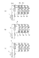
請求項14記載の発明は、複数の利用側手段が個々に放熱若しくは吸熱が行えるものに対して適用した場合であって、図12に示すように、冷媒が加熱されて蒸発する温熱源手段 (1) と、該温熱源手段 (1) にガス流通管 (4) 及び液流通管 (5) によって接続されて温熱源手段 (1) との間で閉回路を形成し、且つ放熱により冷媒を凝縮可能とする冷熱源手段 (2) と、ガス配管 (6) を介して上記ガス流通管 (4) に接続されると共に、液配管 (7) を介して液流通管 (5) に接続された利用側手段 (3) と、上記ガス流通管 (4) とガス配管 (6) との間のガス冷媒の流通状態を切換えるガス流路切換え手段 (8) と、上記液流通管 (5) と液配管 (7) との間の液冷媒の流通状態を切換える液流路切換え手段 (9) と、上記利用側手段 (3) の運転状態に応じて該利用側手段 (3) に対する冷媒の流通状態を切換えるように、ガス流路切換え手段 (8) 及び液流路切換え手段 (9) の少なくとも一方を制御する切換え制御手段 (C) とを備えている。そして、複数の利用側手段(3a〜3d)を備え、各利用側手段(3a〜3d)を、ガス配管(6)を介してガス流通管(4)に、液配管(7)を介して液流通管(5)に夫々接続して、各々個別に放熱運転と吸熱運転とを選択可能とする。また、切換え制御手段(C)が、上記利用側手段(3a〜3d)全体としての熱交換状態が放熱状態である時、温熱源手段(1)からのガス冷媒を放熱運転する利用側手段(3)において所定の凝縮温度で凝縮させるようにガス流路切換え手段(8)を切換えると共に、上記凝縮温度よりも低い温度で冷媒を凝縮させる冷熱源手段(2)と放熱運転する利用側手段(3)との圧力差及び吸熱運転する利用側手段(3)と放熱運転する利用側手段(3)との圧力差により、放熱運転する利用側手段(3)で凝縮された冷媒を冷熱源手段(2)と吸熱運転する利用側手段(3)とに所定の分配比率で分配供給するように液流路切換え手段(9)を切換え、更に、冷熱源手段(2)におけるガス冷媒の凝縮により生じる冷熱源手段(2)と吸熱運転する利用側手段(3)との圧力差により、冷熱源手段(2)の圧力降下に伴って減圧し蒸発する上記吸熱運転する利用側手段(3)の冷媒を冷熱源手段(2)に供給するようにガス流路切換え手段(8)を切換える構成としている。
【0037】
この構成により、複数の利用側手段(3a〜3d)が備えられ、各利用側手段(3a〜3d)が各々個別に放熱運転と吸熱運転とが選択可能となっているものに対し、利用側手段(3a〜3d)全体としての熱交換状態が放熱状態である時、上述した請求項2記載の発明に係る作用と略同様の作用が得られることになる。
【0038】
請求項15記載の発明は、冷熱源手段に貯留される液冷媒を回収するための構成であって、上記請求項14記載の熱搬送装置において、上述した請求項3記載の発明と略同様の構成を備えている。
【0039】
この構成により、上述した請求項14記載の発明に係る作用において冷熱源手段(2)における液冷媒の貯留量が所定量以上に達した時に、この液冷媒が温熱源手段(1)に回収されることになる。
【0040】
請求項16記載の発明も、複数の利用側手段が個々に放熱若しくは吸熱が行えるものに対して適用した場合であって、冷媒が加熱されて蒸発する温熱源手段 (1) と、該温熱源手段 (1) にガス流通管 (4) 及び液流通管 (5) によって接続されて温熱源手段 (1) との間で閉回路を形成し、且つ放熱により冷媒を凝縮可能とする冷熱源手段 (2) と、ガス配管 (6) を介して上記ガス流通管 (4) に接続されると共に、液配管 (7) を介して液流通管 (5) に接続された利用側手段 (3) と、上記ガス流通管 (4) とガス配管 (6) との間のガス冷媒の流通状態を切換えるガス流路切換え手段 (8) と、上記液流通管 (5) と液配管 (7) との間の液冷媒の流通状態を切換える液流路切換え手段 (9) と、上記利用側手段 (3) の運転状態に応じて該利用側手段 (3) に対する冷媒の流通状態を切換えるように、ガス流路切換え手段 (8) 及び液流路切換え手段 (9) の少なくとも一方を制御する切換え制御手段 (C) とを備えている。そして、複数の利用側手段(3a〜3d)を備え、各利用側手段(3a〜3d)を、ガス配管(6)を介してガス流通管(4)に、液配管(7)を介して液流通管(5)に夫々接続して、各々個別に放熱運転と吸熱運転とを選択可能とする。そして、切換え制御手段(C)が、上記利用側手段(3a〜3d)全体としての熱交換状態が吸熱状態である時、温熱源手段(1)からのガス冷媒を冷熱源手段(2)に供給して冷熱源手段(2)の液冷媒を吸熱運転する利用側手段(3)に押出すようにガス流路切換え手段(8)及び液流路切換え手段(9)を切換え、上記冷熱源手段(2)にガス冷媒が、吸熱運転する利用側手段(3)に液冷媒が夫々導入されている状態で、冷熱源手段(2)におけるガス冷媒を凝縮させた時、冷熱源手段(2)の圧力降下により生じる吸熱運転する利用側手段(3)と冷熱源手段(2)との圧力差により、吸熱運転する利用側手段(3)で蒸発する冷媒を冷熱源手段(2)に供給すると共に、温熱源手段(1)からのガス冷媒を放熱運転する利用側手段(3)に供給して該利用側手段(3)において所定の凝縮温度で凝縮させると共に放熱運転する利用側手段(3)における凝縮温度よりも低い温度で冷媒が凝縮する冷熱源手段(2)と放熱運転する利用側手段(3)との圧力差により、放熱運転する利用側手段(3)で凝縮された冷媒を冷熱源手段(2)に供給するようにガス流路切換え手段(8)及び液流路切換え手段(9)を切換える構成としている。
【0041】
この構成により、複数の利用側手段(3a〜3d)が備えられ、各利用側手段(3a〜3d)が各々個別に放熱運転と吸熱運転とが選択可能となっているものに対し、利用側手段(3a〜3d)全体としての熱交換状態が吸熱状態である時、上述した請求項6記載の発明に係る作用と略同様の作用が得られることになる。
【0042】
請求項17記載の発明は、冷熱源手段に貯留される液冷媒を回収するための構成であって、上記請求項16記載の熱搬送装置において、上述した請求項7記載の発明と略同様の構成を備えている。
【0043】
この構成により、上述した請求項16記載の発明に係る作用において温熱源手段(1)における液冷媒の貯留量が所定量以下に達した時に、この液冷媒が温熱源手段(1)に回収されることになる。
【0044】
請求項18記載の発明は、冷媒が加熱されて蒸発する温熱源手段 (1) と、該温熱源手段 (1) にガス流通管 (4) 及び液流通管 (5) によって接続されて温熱源手段 (1) との間で閉回路を形成し、且つ放熱により冷媒を凝縮可能とする冷熱源手段 (2) と、ガス配管 (6) を介して上記ガス流通管 (4) に接続されると共に、液配管 (7) を介して液流通管 (5) に接続された利用側手段 (3) と、上記ガス流通管 (4) とガス配管 (6) との間のガス冷媒の流通状態を切換えるガス流路切換え手段 (8) と、上記液流通管 (5) と液配管 (7) との間の液冷媒の流通状態を切換える液流路切換え手段 (9) と、上記利用側手段 (3) の運転状態に応じて該利用側手段 (3) に対する冷媒の流通状態を切換えるように、ガス流路切換え手段 (8) 及び液流路切換え手段 (9) の少なくとも一方を制御する切換え制御手段 (C) とを備えている。そして、上述した請求項14〜17記載の切換え制御手段 (C) などの構成を兼ね備えたものである。
【0045】
この構成により、上述した請求項14〜17記載の発明に係る作用が共に得られる。
【0046】
請求項19記載の発明は、上記請求項18記載の熱搬送装置においてガス流路切換え手段を具体化したものであって、該ガス流路切換え手段(8)に、ガス流通管(4)におけるガス配管(6)の接続位置と冷熱源手段(2)との間に設けられた第1の開閉弁(EV1)と、各ガス配管(6a〜6d)に設けられた第2の開閉弁(EV2-1〜EV2-4)と、上記第1の開閉弁(EV1)及び冷熱源手段(2)の間と各第2の開閉弁(EV2-1〜EV2-4)及び利用側手段(3a〜3d)の間とを接続する複数の接続管(10a〜10d)と、該各接続管(10a〜10d)に設けられた第3の開閉弁(EV3-1〜EV3-4)及び利用側手段(3a〜3d)から冷熱源手段(2)へのガス冷媒の流通のみを許容する逆止弁(CVG)とを備えさせる。そして、切換え制御手段(C)が、上記第1の開閉弁(EV1)を、利用側手段(3a〜3d)全体としての熱交換状態が放熱状態である時及び利用側手段(3a〜3d)全体としての熱交換状態が吸熱状態であって吸熱運転される利用側手段(3)から冷熱源手段(2)へのガス冷媒供給時に閉鎖し、各利用側手段(3a〜3d)全体としての熱交換状態が吸熱状態であって冷熱源手段(2)から吸熱運転される利用側手段(3)への液冷媒供給時及び冷熱源手段(2)の液冷媒を温熱源手段(1)に回収する時に開放し、上記第2の開閉弁(EV2-1〜EV2-4)を、接続している利用側手段(3a〜3d)の放熱運転時にのみ開放し、上記第3の開閉弁(EV3-1〜EV3-4)を、接続している利用側手段(3a〜3d)の吸熱運転時にのみ開放する構成としている。
【0047】
この構成により、上述した請求項18記載の発明に係る作用を得るためのガス流路切換え手段(8)の具体構成が得られる。
【0048】
請求項20記載の発明は、上記請求項18記載の発明において液流路切換え手段を具体化したものであって、該液流路切換え手段(9)に、液流通管(5)における液配管(7)の接続位置と温熱源手段(1)との間に設けられた第1の開閉弁(EV4)及び冷熱源手段(2)から温熱源手段(1)への液冷媒の流通のみを許容する逆止弁(CVL)と、各液配管(7a〜7d)に設けられた第2の開閉弁(EV5-1〜EV5-4)とを備えさせる。そして、切換え制御手段(C)が、上記第1の開閉弁(EV4)を、冷熱源手段(2)の液冷媒を温熱源手段(1)に回収する際に開放し、利用側手段(3a〜3d)全体としての熱交換状態が吸熱状態である時に閉鎖すると共に、上記第2の開閉弁(EV5-1〜EV5-4)を、接続される利用側手段(3a〜3d)の放熱運転時及び吸熱運転時に開放し、冷熱源手段(2)の液冷媒を温熱源手段(1)に回収する際に閉鎖する構成としている。
【0049】
この構成により、上述した請求項18記載の発明に係る作用を得るための液流路切換え手段(9)の具体構成が得られる。
【0050】
請求項21記載の発明は、上記請求項6〜20の何れか1記載の熱搬送装置において、図18に示すように、液冷媒を貯留可能な受液手段(22)を、一端がガス流通管(4)におけるガス配管(6)の接続位置と冷熱源手段(2)との間に、他端が液流通管(5)における液配管(7)の接続位置と冷熱源手段(2)との間に夫々接続された分岐管(23)を介して冷熱源手段(2)に並列に接続した構成としている。
【0051】
この構成により、受液手段(22)に液冷媒を貯留できるので、冷熱源手段(2)に液冷媒が貯留されることによる熱交換面積の減少を回避することができ、この冷熱源手段(2)の熱交換効率を高く維持できる。
【0052】
請求項22記載の発明は、上記請求項1〜5および21の何れか記載の熱搬送装置において、図19に示すように、ガス流通管(4)における分岐管(23)との接続部分と冷熱源手段(2)との間に、冷熱源手段(2)への冷媒供給状態を変更可能とする開閉弁(EV11)を設けた構成としている。
【0053】
この構成により、液冷媒を冷熱源手段(2)や受液手段(22)から排出する際に開閉弁(EV11)を閉鎖することにより、冷熱源手段(2)に温熱源手段(1)からのガス冷媒が供給されなくなるので、冷熱源手段(2)が不必要に加熱されることを防止できる。
【0054】
請求項23〜40記載の発明は、冷熱源熱交換器を複数備えさせたものである。請求項23記載の発明は、上記請求項1記載の熱搬送装置において、複数の冷熱源手段(2a,2b)を備えさせ、各冷熱源手段(2a,2b)を、温熱源手段(1)にガス流通管(4a,4b)及び液流通管(5a,5b)によって接続して温熱源手段(1)との間で閉回路を形成し、且つ放熱により冷媒を凝縮可能とする。そして、ガス流路切換え手段(8)が、各ガス流通管(4a,4b)とガス配管(6)との間のガス冷媒の流通状態を切換え、液流路切換え手段(9)が、各液流通管(5a,5b)と液配管(7)との間の液冷媒の流通状態を切換える構成としている。
【0055】
この構成では、常に一部の冷熱源手段を利用側手段(3)との間で冷媒を循環させながら各冷熱源手段(2a,2b)同士で利用側手段(3)に対する接続状態を切換えるようにすれば常に利用側手段(3)において放熱或いは吸熱が行われ、該利用側手段(3)において連続した放熱運転が行われることになる。
【0056】
請求項24記載の発明は、利用側手段が放熱するものであって、図21に示すように、上記請求項23記載の熱搬送装置において、各冷熱源手段(2a,2b)を温熱源手段(1)よりも上方に配置させ、利用側手段(3)を、上記各ガス流通管(4a,4b)及び液流通管(5a,5b)に対してガス配管(6)及び液配管(7)により夫々接続させる。そして、切換え制御手段(C)が、上記利用側手段(3)の放熱運転時、上記温熱源手段(1)からのガス冷媒を一部の冷熱源手段(2a)及び利用側手段(3)に供給して該利用側手段(3)において所定の凝縮温度で凝縮させるようにガス流路切換え手段(8)を切換えると共に、上記凝縮温度よりも低い温度で冷媒を凝縮させる他部の冷熱源手段(2b)と利用側手段(3)との圧力差により、利用側手段(3)で凝縮された冷媒を他部の冷熱源手段(2b)に供給するように液流路切換え手段(9)を切換え、上記他部の冷熱源手段(2b)における液冷媒の貯留量が所定量以上に達したとき、上記一部の冷熱源手段(2a)へのガス冷媒の供給を停止すると共に温熱源手段(1)からのガス冷媒を他部の冷熱源手段(2b)及び利用側手段(3)に供給して、温熱源手段(1)と他部の冷熱源手段(2b)とを均圧し且つ利用側手段(3)においてガス冷媒を所定の凝縮温度で凝縮させるようにガス流路切換え手段(8)を切換えると共に、上記凝縮温度よりも低い温度で冷媒を凝縮させる一部の冷熱源手段(2a)と利用側手段(3)との圧力差により、利用側手段(3)で凝縮された冷媒を一部の冷熱源手段(2a)に供給し、且つ他部の冷熱源手段(2b)から温熱源手段(1)への液冷媒の流通を許容することにより、この他部の冷熱源手段(2b)の液冷媒を温熱源手段(1)に回収するように液流路切換え手段(9)を切換える構成としている。
【0057】
この構成により、利用側手段(3)の放熱運転時、一部の冷熱源手段から常に液冷媒を温熱源手段(1)へ回収しながら、他の冷熱源手段と利用側手段(3)との間で、該利用側手段(3)において放熱が行われるように冷媒を流すことにより、利用側手段(3)において連続した放熱運転が行われることになる。
【0058】
請求項27記載の発明は、利用側手段が吸熱するものであって、図23に示すように、冷媒が加熱されて蒸発する温熱源手段 (1) と、該温熱源手段 (1) にガス流通管 (4) 及び液流通管 (5) によって接続されて温熱源手段 (1) との間で閉回路を形成し、且つ放熱により冷媒を凝縮可能とする冷熱源手段 (2) と、ガス配管 (6) を介して上記ガス流通管 (4) に接続されると共に、液配管 (7) を介して液流通管 (5) に接続された利用側手段 (3) と、上記ガス流通管 (4) とガス配管 (6) との間のガス冷媒の流通状態を切換えるガス流路切換え手段 (8) と、上記液流通管 (5) と液配管 (7) との間の液冷媒の流通状態を切換える液流路切換え手段 (9) と、上記利用側手段 (3) の運転状態に応じて該利用側手段 (3) に対する冷媒の流通状態を切換えるように、ガス流路切換え手段 (8) 及び液流路切換え手段 (9) の少なくとも一方を制御する切換え制御手段 (C) とを備えている。そして、上記冷熱源手段 (2a,2b) は複数備えられ、各冷熱源手段 (2a,2b) は、温熱源手段 (1) にガス流通管 (4a,4b) 及び液流通管 (5a,5b) によって接続されて温熱源手段 (1) との間で閉回路を形成し、且つ放熱により冷媒を凝縮可能となっており、上記ガス流路切換え手段 (8) は、各ガス流通管 (4a,4b) とガス配管 (6) との間のガス冷媒の流通状態を切換え、液流路切換え手段 (9) は、各液流通管 (5a,5b) と液配管 (7) との間の液冷媒の流通状態を切換えるようになっている。加えて、上記利用側手段(3)を、上記各ガス流通管(4a,4b)及び液流通管(5a,5b)に対してガス配管(6e,6f)及び液配管(7e,7f)により夫々接続させる。そして、切換え制御手段(C)が、上記利用側手段(3)の吸熱運転時、上記温熱源手段(1)からのガス冷媒を一部の冷熱源手段(2a)に供給して該一部の冷熱源手段(2a)の液冷媒を利用側手段(3)に押出すようにガス流路切換え手段(8)及び液流路切換え手段(9)を切換えると共に、他部の冷熱源手段(2b)にガス冷媒が、利用側手段(3)に液冷媒が夫々導入されている状態で、他部の冷熱源手段(2b)におけるガス冷媒の凝縮により生じる利用側手段(3)と他部の冷熱源手段(2b)との圧力差により、他部の冷熱源手段(2b)の圧力降下に伴って減圧し蒸発する利用側手段(3)の冷媒を他部の冷熱源手段(2b)に供給するようにガス流路切換え手段(8)を切換え、上記他部の冷熱源手段(2b)における液冷媒の貯留量が所定量以上に達したとき、上記一部の冷熱源手段(2a)へのガス冷媒の供給を停止すると共に温熱源手段(1)からのガス冷媒を他部の冷熱源手段(2b)に供給して該他部の冷熱源手段(2b)の液冷媒を利用側手段(3)に押出すようにガス流路切換え手段(8)及び液流路切換え手段(9)を切換え、更に、一部の冷熱源手段(2a)にガス冷媒が、利用側手段(3)に液冷媒が夫々導入されている状態で、一部の冷熱源手段(2a)におけるガス冷媒の凝縮により生じる利用側手段(3)と一部の冷熱源手段(2a)との圧力差により、一部の冷熱源手段(2a)の圧力降下に伴って減圧し蒸発する利用側手段(3)の冷媒を一部の冷熱源手段(2a)に供給するようにガス流路切換え手段(8)を切換える構成としている。
【0059】
この構成により、利用側手段(3)の吸熱運転時、該利用側手段(3)において連続した吸熱動作が行われることになる。
【0060】
請求項28記載の発明は、上記請求項27記載の熱搬送装置において、冷熱源手段に貯留される液冷媒を回収するための構成であって、上述した請求項7記載の発明と略同様の構成である。
【0061】
この構成により、上述した請求項27記載の発明に係る作用において温熱源手段(1)における液冷媒の貯留量が所定量以下に達した時に、この液冷媒が温熱源手段(1)に回収されることになる。
【0062】
請求項31記載の発明は、利用側手段が吸熱及び放熱するものであって、冷媒が加熱されて蒸発する温熱源手段 (1) と、該温熱源手段 (1) にガス流通管 (4) 及び液流通管 (5) によって接続されて温熱源手段 (1) との間で閉回路を形成し、且つ放熱により冷媒を凝縮可能とする冷熱源手段 (2) と、ガス配管 (6) を介して上記ガス流通管 (4) に接続されると共に、液配管 (7) を介して液流通管 (5) に接続された利用側手段 (3) と、上記ガス流通管 (4) とガス配管 (6) との間のガス冷媒の流通状態を切換えるガス流路切換え手段 (8) と、上記液流通管 (5) と液配管 (7) との間の液冷媒の流通状態を切換える液流路切換え手段 (9) と、上記利用側手段 (3) の運転状態に応じて該利用側手段 (3) に対する冷媒の流通状態を切換えるように、ガス流路切換え手段 (8) 及び液流路切換え手段 (9) の少なくとも一方を制御する切換え制御手段 (C) とを備えている。そして、上記冷熱源手段 (2a,2b) は複数備えられ、各冷熱源手段 (2a,2b) は、温熱源手段 (1) にガス流通管 (4a,4b) 及び液流通管 (5a,5b) によって接続されて温熱源手段 (1) との間で閉回路を形成し、且つ放熱により冷媒を凝縮可能となっており、上記ガス流路切換え手段 (8) は、各ガス流通管 (4a,4b) とガス配管 (6) との間のガス冷媒の流通状態を切換え、液流路切換え手段 (9) は、各液流通管 (5a,5b) と液配管 (7) との間の液冷媒の流通状態を切換えるようになっている。加えて、上述した請求項24及び27記載の発明の構成を兼ね備えている。
【0063】
この構成により、上述した請求項24及び27記載の発明に係る作用が共に得られる。
【0064】
請求項32記載の発明は、上述した請求項31記載の発明において、冷熱源手段(2)の液冷媒を温熱源手段(1)に回収するものであって、上述した請求項28記載の発明と同様の構成を備えている。
【0065】
この構成により、上述した請求項31記載の発明に係る作用において、温熱源手段(1)における液冷媒の貯留量が所定量以下に達した時に、この液冷媒が温熱源手段(1)に回収されることになる。
【0066】
請求項35記載の発明は、複数の利用側手段が個々に放熱若しくは吸熱が行えるものに対して適用した場合であって、図28に示すように、冷媒が加熱されて蒸発する温熱源手段 (1) と、該温熱源手段 (1) にガス流通管 (4) 及び液流通管 (5) によって接続されて温熱源手段 (1) との間で閉回路を形成し、且つ放熱により冷媒を凝縮可能とする冷熱源手段 (2) と、ガス配管 (6) を介して上記ガス流通管 (4) に接続されると共に、液配管 (7) を介して液流通管 (5) に接続された利用側手段 (3) と、上記ガス流通管 (4) とガス配管 (6) との間のガス冷媒の流通状態を切換えるガス流路切換え手段 (8) と、上記液流通管 (5) と液配管 (7) との間の液冷媒の流通状態を切換える液流路切換え手段 (9) と、上記利用側手段 (3) の運転状態に応じて該利用側手段 (3) に対する冷媒の流通状態を切換えるように、ガス流路切換え手段 (8) 及び液流路切換え手段 (9) の少なくとも一方を制御する切換え制御手段 (C) とを備えている。そして、上記冷熱源手段 (2a,2b) は複数備えられ、各冷熱源手段 (2a,2b) は、温熱源手段 (1) にガス流通管 (4a,4b) 及び液流通管 (5a,5b) によって接続されて温熱源手段 (1) との間で閉回路を形成し、且つ放熱により冷媒を凝縮可能となっており、上記ガス流路切換え手段 (8) は、各ガス流通管 (4a,4b) とガス配管 (6) との間のガス冷媒の流通状態を切換え、液流路切換え手段 (9) は、各液流通管 (5a,5b) と液配管 (7) との間の液冷媒の流通状態を切換えるようになっている。加えて、上記各冷熱源手段(2a,2b)を温熱源手段(1)よりも上方に配置させ、複数の利用側手段(3a〜3d)を備えさせえて、各利用側手段(3a〜3d)を、ガス配管(6)を介して各ガス流通管(4a,4b)に、液配管(7e,7f)を介して各液流通管(5a,5b)に夫々接続して、各々個別に放熱運転と吸熱運転とを選択可能とする。そして、切換え制御手段(C)が、利用側手段(3a〜3d)全体としての熱交換状態が放熱状態である時、温熱源手段(1)からのガス冷媒を一部の冷熱源手段(2a)及び放熱運転する利用側手段(3)に供給して該利用側手段(3)において所定の凝縮温度で凝縮させるようにガス流路切換え手段(8)を切換えると共に、上記凝縮温度よりも低い温度で冷媒を凝縮させる他部の冷熱源手段(2b)と放熱運転する利用側手段(3)との圧力差及び吸熱運転する利用側手段(3)と放熱運転する利用側手段(3)との圧力差により、放熱運転する利用側手段(3)で凝縮された冷媒を他部の冷熱源手段(2b)と吸熱運転する利用側手段(3)とに所定の分配比率で分配供給するように液流路切換え手段(9)を切換え、更に、他部の冷熱源手段(2b)におけるガス冷媒の凝縮により生じる該他部の冷熱源手段(2b)と吸熱運転する利用側手段(3)との圧力差により、他部の冷熱源手段(2b)の圧力降下に伴って減圧し蒸発する上記吸熱運転する利用側手段(3)の冷媒を他部の冷熱源手段(2b)に供給するようにガス流路切換え手段(8)を切換え、上記他部の冷熱源手段(2b)における液冷媒の貯留量が所定量以上に達したとき、上記一部の冷熱源手段(2a)へのガス冷媒の供給を停止すると共に温熱源手段(1)からのガス冷媒を他部の冷熱源手段(2b)及び放熱運転する利用側手段(3)に供給して、温熱源手段(1)と他部の冷熱源手段(2b)とを均圧し且つ放熱運転する利用側手段(3)においてガス冷媒を所定の凝縮温度で凝縮させるようにガス流路切換え手段(8)を切換えると共に、上記凝縮温度よりも低い温度で冷媒を凝縮させる一部の冷熱源手段(2a)と放熱運転する利用側手段(3)との圧力差及び吸熱運転する利用側手段(3)と放熱運転する利用側手段(3)との圧力差により、放熱運転する利用側手段(3)で凝縮された冷媒を一部の冷熱源手段(2a)と吸熱運転する利用側手段(3)とに所定の分配比率で分配供給し、且つ他部の冷熱源手段(2b)から温熱源手段(1)への液冷媒の流通を許容することにより、この他部の冷熱源手段(2b)の液冷媒を温熱源手段(1)に回収するように液流路切換え手段(9)を切換える構成としている。
【0067】
この構成により、複数の利用側手段(3a〜3d)が備えられ、各利用側手段(3a〜3d)が各々個別に放熱運転と吸熱運転とが選択可能となっているものに対し、利用側手段(3a〜3d)全体としての熱交換状態が放熱状態である時、上述した請求項24記載の発明に係る作用と略同様の作用が得られることになる。
【0068】
請求項36記載の発明も、複数の利用側手段が個々に放熱若しくは吸熱が行えるものに対して適用した場合であって、冷媒が加熱されて蒸発する温熱源手段 (1) と、該温熱源手 段 (1) にガス流通管 (4) 及び液流通管 (5) によって接続されて温熱源手段 (1) との間で閉回路を形成し、且つ放熱により冷媒を凝縮可能とする冷熱源手段 (2) と、ガス配管 (6) を介して上記ガス流通管 (4) に接続されると共に、液配管 (7) を介して液流通管 (5) に接続された利用側手段 (3) と、上記ガス流通管 (4) とガス配管 (6) との間のガス冷媒の流通状態を切換えるガス流路切換え手段 (8) と、上記液流通管 (5) と液配管 (7) との間の液冷媒の流通状態を切換える液流路切換え手段 (9) と、上記利用側手段 (3) の運転状態に応じて該利用側手段 (3) に対する冷媒の流通状態を切換えるように、ガス流路切換え手段 (8) 及び液流路切換え手段 (9) の少なくとも一方を制御する切換え制御手段 (C) とを備えている。そして、上記冷熱源手段 (2a,2b) は複数備えられ、各冷熱源手段 (2a,2b) は、温熱源手段 (1) にガス流通管 (4a,4b) 及び液流通管 (5a,5b) によって接続されて温熱源手段 (1) との間で閉回路を形成し、且つ放熱により冷媒を凝縮可能となっており、上記ガス流路切換え手段 (8) は、各ガス流通管 (4a,4b) とガス配管 (6) との間のガス冷媒の流通状態を切換え、液流路切換え手段 (9) は、各液流通管 (5a,5b) と液配管 (7) との間の液冷媒の流通状態を切換えるようになっている。加えて、上記複数の利用側手段(3a〜3d)を備えさせ、各利用側手段(3a〜3d)を、ガス配管(6)を介して各ガス流通管(4a,4b)に、液配管(7e,7f)を介して各液流通管(5a,5b)に夫々接続して、各々個別に放熱運転と吸熱運転とを選択可能とする。そして、切換え制御手段(C)が、利用側手段(3a〜3d)全体としての熱交換状態が吸熱状態である時、温熱源手段(1)からのガス冷媒を一部の冷熱源手段(2a)及び放熱運転する利用側手段(3)に供給して該利用側手段(3)において所定の凝縮温度で凝縮させ、この放熱運転する利用側手段(3)と吸熱運転する利用側手段(3)との圧力差により、放熱運転する利用側手段(3)で凝縮された冷媒を吸熱運転する利用側手段(3)に供給すると共に、一部の冷熱源手段(2a)の液冷媒を吸熱運転する利用側手段(3)に押出すようにガス流路切換え手段(8)及び液流路切換え手段(9)を切換え、上記他部の冷熱源手段(2b)におけるガス冷媒の凝縮により生じる該他部の冷熱源手段(2b)と吸熱運転する利用側手段(3)との圧力差により、他部の冷熱源手段(2b)の圧力降下に伴って減圧し蒸発する上記吸熱運転する利用側手段(3)の冷媒を他部の冷熱源手段(2b)に供給するようにガス流路切換え手段(8)を切換え、上記他部の冷熱源手段(2b)における液冷媒の貯留量が所定量以上に達したとき、上記一部の冷熱源手段(2a)へのガス冷媒の供給を停止すると共に温熱源手段(1)からのガス冷媒を他部の冷熱源手段(2b)及び放熱運転する利用側手段(3)に供給して、該利用側手段(3)において所定の凝縮温度で凝縮させ、この放熱運転する利用側手段(3)と吸熱運転する利用側手段(3)との圧力差により、放熱運転する利用側手段(3)で凝縮された冷媒を吸熱運転する利用側手段(3)に供給すると共に、他部の冷熱源手段(2b)の液冷媒を吸熱運転する利用側手段(3)に押出すようにガス流路切換え手段(8)及び液流路切換え手段(9)を切換え、上記一部の冷熱源手段(2a)におけるガス冷媒の凝縮により生じる該一部の冷熱源手段(2a)と吸熱運転する利用側手段(3)との圧力差により、一部の冷熱源手段(2a)の圧力降下に伴って減圧し蒸発する上記吸熱運転する利用側手段(3)の冷媒を他部の冷熱源手段(2b)に供給するようにガス流路切換え手段(8)を切換える構成としている。
【0069】
この構成により、複数の利用側手段(3a〜3d)が備えられ、各利用側手段(3a〜3d)が各々個別に放熱運転と吸熱運転とが選択可能となっているものに対し、利用側手段(3a〜3d)全体としての熱交換状態が吸熱状態である時、上述した請求項27記載の発明に係る作用と略同様の作用が得られることになる。
【0070】
請求項37記載の発明は、冷熱源手段に貯留される液冷媒を回収するための構成であって、上記請求項36記載熱搬送装置において、上述した請求項28記載の発明と略同様の構成を備えている。
【0071】
この構成により、上述した請求項36記載の発明に係る作用において温熱源手段(1)における液冷媒の貯留量が所定量以下に達した時に、この液冷媒が温熱源手段(1)に回収されることになる。
【0072】
請求項38記載の発明は、冷媒が加熱されて蒸発する温熱源手段 (1) と、該温熱源手段 (1) にガス流通管 (4) 及び液流通管 (5) によって接続されて温熱源手段 (1) との間で閉回路を形成し、且つ放熱により冷媒を凝縮可能とする冷熱源手段 (2) と、ガス配管 (6) を介して上記ガス流通管 (4) に接続されると共に、液配管 (7) を介して液流通管 (5) に接続された利用側手段 (3) と、上記ガス流通管 (4) とガス配管 (6) との間のガス冷媒の流通状態を切換えるガス流路切換え手段 (8) と、上記液流通管 (5) と液配管 (7) との間の液冷媒の流通状態を切換える液流路切換え手段 (9) と、上記利用側手段 (3) の運転状態に応じて該利用側手段 (3) に対する冷媒の流通状態を切換えるように、ガス流路切換え手段 (8) 及び液流路切換え手段 (9) の少なくとも一方を制御する切換え制御手段 (C) とを備えている。そして、上記冷熱源手段 (2a,2b) は複数備えられ、各冷熱源手段 (2a,2b) は、温熱源手段 (1) にガス流通管 (4a,4b) 及び液流通管 (5a,5b) によって接続されて温熱源手段 (1) との間で閉回路を形成し、且つ放熱により冷媒を凝縮可能となっており、上記ガス流路切換え手段 (8) は、各ガス流通管 (4a,4b) とガス配管 (6) との間のガス冷媒の流通状態を切換え、液流路切換え手段 (9) は、各液流通管 (5a,5b) と液配管 (7) との間の液冷媒の流通状態を切換えるようになっている。加えて、上述した請求項35〜37記載の切換え制御手段 (C) などの構成を兼ね備えたものである。
【0073】
この構成により、上述した請求項35〜37記載の発明に係る作用が共に得られる。
【0074】
請求項25記載の発明は、上記請求項24記載の発明においてガス流路切換え手段を具体化したものであって、該ガス流路切換え手段(8)に、各ガス流通管(4a,4b)におけるガス配管(6)の接続位置と冷熱源手段(2a,2b)との間に夫々設けられた開閉弁(EV1-1,EV1-2)を備えさせる。そして、切換え制御手段(C)が、上記各開閉弁(EV1-1,EV1-2)を、接続している冷熱源手段(2a,2b)に利用側手段(3)から液冷媒が供給される時に閉鎖し、且つ接続している冷熱源手段(2a,2b)における液冷媒の貯留量が所定量以上に達した時に開放する構成としている。
【0075】
請求項29記載の発明は、上記請求項28記載の熱搬送装置において、ガス流路切換え手段を具体化したものであって、該ガス流路切換え手段(8)に、各ガス流通管(4a,4b)におけるガス配管(6e,6f)の接続位置と温熱源手段(1)との間に夫々設けられた開閉弁(EV1-1,EV1-2)と、各ガス配管(6e,6f)に設けられて、利用側手段(3)から冷熱源手段(2a,2b)へのガス冷媒の流通のみを許容する逆止弁(CVG1,CVG2)とを備えさせる。そして、切換え制御手段(C)が、上記各開閉弁(EV1-1,EV1-2)を、接続している冷熱源手段(2a,2b)から利用側手段(3)への液冷媒供給時及び温熱源手段(1)における液冷媒の貯留量が所定量以下に達した時に開放し、接続している冷熱源手段(2a,2b)への利用側手段(3)からのガス冷媒供給時に閉鎖する構成としている。
【0076】
請求項33記載の発明は、上記請求項32記載の発明においてガス流路切換え手段を具体化したものである。つまり、このガス流路切換え手段(8)に、各ガス流通管(4a,4b)におけるガス配管(6)の接続位置と冷熱源手段(2a,2b)との間に設けられた第1の開閉弁(EV1-1,EV1-2)と、ガス配管(6)に設けられた第2の開閉弁(EV2)と、上記第1の開閉弁(EV1-1,EV1-2)及び冷熱源手段(2a,2b)の間と第2の開閉弁(EV2)及び利用側手段(3)の間とを接続する接続管(20)と、該接続管(20)に設けられた第3の開閉弁(EV3)及び利用側手段(3)から冷熱源手段(2a,2b)へのガス冷媒の流通のみを許容する逆止弁(CVG1,CVG2)とを備えさせる。そして、切換え制御手段(C)が、上記第1の開閉弁(EV1-1,EV1-2)を、接続している冷熱源手段(2a,2b)に対して、利用側手段(3)の放熱運転時に該利用側手段(3)から液冷媒が供給される時及び利用側手段(3)の吸熱運転時に該利用側手段(3)からガス冷媒が供給される時に閉鎖し、接続している冷熱源手段(2a,2b)に、温熱源手段(1)からガス冷媒が供給される時に開放し、上記第2の開閉弁(EV2)を、利用側手段(3)の放熱運転時にのみ開放し、上記第3の開閉弁(EV3)を、利用側手段(3)の吸熱運転時にのみ開放する構成としている。
【0077】
請求項39記載の発明は、上記請求項38記載の発明においてガス流路切換え手段を具体化したものであって、該ガス流路切換え手段(8)に、各ガス流通管(4a,4b)におけるガス配管(6)の接続位置と冷熱源手段(2a,2b)との間に設けられた第1の開閉弁(EV1-1,EV1-2)と、各ガス配管(6a〜6d)に設けられた第2の開閉弁(EV2-1〜EV2-4)と、上記第1の開閉弁(EV1-1,EV1-2)及び冷熱源手段(2a,2b)の間と各第2の開閉弁(EV2-1〜EV2-4)及び利用側手段(3a〜3d)の間とを接続する複数の接続管(20)と、該各接続管(20)に設けられた第3の開閉弁(EV3-1〜EV3-4)及び利用側手段(3a〜3d)から冷熱源手段(2a,2b)へのガス冷媒の流通のみを許容する逆止弁(CVG1,CVG2)とを備えさせる。そして、切換え制御手段(C)が、上記第1の開閉弁(EV1-1,EV1-2)を、接続している冷熱源手段(2a,2b)に対して、利用側手段(3a〜3d)全体としての熱交換状態が放熱状態である時における放熱運転する利用側手段(3)からの液冷媒供給時、及び利用側手段(3a〜3d)全体としての熱交換状態が吸熱状態である時における吸熱運転する利用側手段(3)からのガス冷媒供給時に閉鎖し、接続している冷熱源手段(2a,2b)に、温熱源手段(1)からガス冷媒が供給される時に開放し、上記第2の開閉弁(EV2-1〜EV2-4)を、接続している利用側手段(3)の放熱運転時にのみ開放し、上記第3の開閉弁(EV3-1〜EV3-4)を、接続している利用側手段(3)の吸熱運転時にのみ開放する構成としている。
【0078】
これら請求項25、29、33及び39記載の発明では、夫々請求項24、27、31及び38記載の発明に係る作用を得るためのガス流路切換え手段(8)の具体構成が得られる。
【0079】
請求項26記載の発明は、上記請求項24記載の発明において液流路切換え手段を具体化したものであって、液流路切換え手段(9)に、各液流通管(5a,5b)における液配管(7e,7f)の接続位置と温熱源手段(1)との間に設けられて、冷熱源手段(2a,2b)から温熱源手段(1)への液冷媒の流通のみを許容する第1の逆止弁(CV1-1,CV1-2)と、上記各液配管液配管(7e,7f)に設けられて、利用側手段(3)から冷熱源手段(2)への液冷媒の流通のみを許容する第2の逆止弁(CV2-1,CV2-2)とを備えさせた構成としている。
【0080】
請求項30記載の発明は、上記請求項28記載の発明において液流路切換え手段を具体化したものであって、該液流路切換え手段(8)に、各液流通管(5a,5b)における液配管(7e,7f)の接続位置と温熱源手段(1)との間に設けられた開閉弁(EV4)及び冷熱源手段(2a,2b)から温熱源手段(1)へのガス冷媒の流通のみを許容する第1の逆止弁(CV1-1,CV1-2)と、上記各液配管(7e,7f)に設けられて、冷熱源手段(2a,2b)から利用側手段(3)への液冷媒の流通のみを許容する第2の逆止弁(CV3-1,CV3-2)とを備えさせる。そして、切換え制御手段(C)が、上記開閉弁(EV4)を、利用側手段(3)の吸熱運転時に閉鎖し、且つ温熱源手段(1)における液冷媒の貯留量が所定量以下に達した時に開放する構成としている。
【0081】
請求項34記載の発明は、上記請求項32記載の発明において液流路切換え手段を具体化したものである。つまり、この液流路切換え手段(9)に、液流通管(5a,5b)における液配管(7e,7f)の接続位置と温熱源手段(1)との間に設けられた第1の開閉弁(EV4)及び冷熱源手段(2a,2b)から温熱源手段(1)への液冷媒の流通のみを許容する逆止弁(CV1-1,CV1-2)と、各液配管(7e,7f)に設けられた第2の開閉弁(EV6-1,EV6-2)とを備えさせる。そして、切換え制御手段(C)が、上記第1の開閉弁(EV4)を、冷熱源手段(2a,2b)の液冷媒を温熱源手段(1)に回収する際に開放し、利用側手段(3)の吸熱運転時に閉鎖すると共に、上記第2の開閉弁(EV6-1,EV6-2)を、利用側手段(3)の放熱運転時に、接続している冷熱源手段(2a,2b)に対して利用側手段(3)から液冷媒が供給される時、及び利用側手段(3)の吸熱運転時に、接続している冷熱源手段(2a,2b)から利用側手段(3)に液冷媒を供給する時に開放し、接続している冷熱源手段(2a,2b)に対して、利用側手段(3)の放熱運転時に温熱源手段(1)からガス冷媒が供給される時、及び利用側手段(3)の吸熱運転時に該利用側手段(3)からガス冷媒が供給される時に閉鎖する構成としている。
【0082】
請求項40記載の発明は、上記請求項38記載の発明において液流路切換え手段を具体化したものであって、該液流路切換え手段(9)に、液流通管(5a,5b)における液配管(7e,7f)の接続位置と温熱源手段(1)との間に設けられた第1の開閉弁(EV4)及び冷熱源手段(2a,2b)から温熱源手段(1)への液冷媒の流通のみを許容する逆止弁(CV1-1,CV1-2)と、各利用側手段(3a〜3d)に対応して液配管(7a〜7d)に設けられた第2の開閉弁(EV5-1〜EV5-4)と、各冷熱源手段(2a,2b)に対応して液配管(7e,7f)に設けられた第3の開閉弁(EV6-1,EV6-2)とを備えさせる。そして、切換え制御手段(C)が、上記第1の開閉弁(EV4)を、冷熱源手段(2a,2b)の液冷媒を温熱源手段(1)に回収する際にのみ開放し、上記第3の開閉弁(EV6-1,EV6-2)を、利用側手段(3a〜3d)全体としての熱交換状態が放熱状態である時に、接続している冷熱源手段(2a,2b)に対して放熱運転する利用側手段(3)からの液冷媒供給時、及び利用側手段(3a〜3d)全体としての熱交換状態が吸熱状態である時に、接続している冷熱源手段(2a,2b)から吸熱運転する利用側手段(3)への液冷媒供給時に開放し、接続している冷熱源手段(2a,2b)に対して、利用側手段(3a〜3d)全体としての熱交換状態が放熱状態である時における温熱源手段(1)からのガス冷媒供給時及び利用側手段(3a〜3d)全体としての熱交換状態が吸熱状態である時における吸熱運転する利用側手段(3)からガス冷媒供給時に閉鎖する構成としている。
【0083】
これら請求項26、30、34及び40記載の発明では、夫々請求項24、27、31及び38記載の発明に係る作用を得るための液流路切換え手段(9)の具体構成が得られる。
【0084】
請求項41〜58記載の発明は、液冷媒を貯留する受液手段を複数備えさせたものである。請求項41記載の発明は、冷媒が加熱されて蒸発する温熱源手段 (1) と、該温熱源手段 (1) にガス流通管 (4) 及び液流通管 (5) によって接続されて温熱源手段 (1) との間で閉回路を形成し、且つ放熱により冷媒を凝縮可能とする冷熱源手段 (2) と、ガス配管 (6) を介して上記ガス流通管 (4) に接続されると共に、液配管 (7) を介して液流通管 (5) に接続された利用側手段 (3) と、上記ガス流通管 (4) とガス配管 (6) との間のガス冷媒の流通状態を切換えるガス流路切換え手段 (8) と、上記液流通管 (5) と液配管 (7) との間の液冷媒の流通状態を切換える液流路切換え手段 (9) と、上記利用側手段 (3) の運転状態に応じて該利用側手段 (3) に対する冷媒の流通状態を切換えるように、ガス流路切換え手段 (8) 及び液流路切換え手段 (9) の少なくとも一方を制御する切換え制御手段 (C) とを備えている。そして、液冷媒を貯留可能な複数の受液手段(25a,25b)を備えさせ、各受液手段(25a,25b)の夫々をガス管(26a,26b)によってガス流通管(4a,4b)に、液管(27a,27b)によって液流通管(5a,5b)に接続する。そして、ガス流路切換え手段(8)が、各ガス流通管(4a,4b)とガス管(26a,26b)との間のガス冷媒の流通状態を切換え、液流路切換え手段(9)が、各液流通管(5a,5b)と液管(27a,27b)との間の液冷媒の流通状態を切換えるようにし、切換え制御手段(C)が、上記利用側手段(3)の運転状態に応じてガス流路切換え手段(8)及び液流路切換え手段(9)の少なくとも一方を制御する構成としている。
【0085】
この構成により、常に一部の受液手段と利用側手段(3)との間で冷媒を循環させながら各受液手段(25a,25b)同士で利用側手段(3)に対する接続状態を切換えるようにすれば常に利用側手段(3)において放熱或いは吸熱が行われ、該利用側手段(3)において連続した放熱運転が行われることになる。
【0086】
請求項42記載の発明は、利用側手段が放熱するものであって、図32に示すように、上記請求項41記載の熱搬送装置において、各受液手段(25a,25b)を温熱源手段(1)よりも上方に配置させ、切換え制御手段(C)が、上記利用側手段(3)の放熱運転時、上記温熱源手段(1)からのガス冷媒を一部の受液手段(25a)及び利用側手段(3)に供給して該利用側手段(3)において所定の凝縮温度で凝縮させるようにガス流路切換え手段(8)を切換えると共に、上記凝縮温度よりも低い温度で冷媒を凝縮させる冷熱源手段(2)に繋がる他部の受液手段(25b)と利用側手段(3)との圧力差により、利用側手段(3)で凝縮された冷媒を他部の受液手段(25b)に供給するように液流路切換え手段(9)を切換え、上記他部の受液手段(25b)における液冷媒の貯留量が所定量以上に達したとき、上記一部の受液手段(25a)へのガス冷媒の供給を停止すると共に温熱源手段(1)からのガス冷媒を他部の受液手段(25b)及び利用側手段(3)に供給して、温熱源手段(1)と他部の受液手段(25b)とを均圧し且つ利用側手段(3)においてガス冷媒を所定の凝縮温度で凝縮させるようにガス流路切換え手段(8)を切換えると共に、上記凝縮温度よりも低い温度で冷媒を凝縮させる冷熱源手段(2)に繋がる一部の受液手段(25a)と利用側手段(3)との圧力差により、利用側手段(3)で凝縮された冷媒を一部の受液手段(25a)に供給し、且つ他部の受液手段(25b)から温熱源手段(1)への液冷媒の流通を許容することにより、この他部の受液手段(25b)の液冷媒を温熱源手段(1)に回収するように液流路切換え手段(9)を切換える構成としている。
【0087】
この構成により、利用側手段(3)の放熱運転時、一部の受液手段から常に液冷媒を温熱源手段(1)へ回収しながら、他の受液手段と利用側手段(3)との間で、該利用側手段(3)において放熱が行われるように冷媒を流すことにより、利用側手段(3)において連続した放熱運転が行われることになる。
【0088】
請求項45記載の発明は、利用側手段が吸熱するものであって、図34に示すように、上記請求項41記載の発明において、切換え制御手段(C)が、上記利用側手段(3)の吸熱運転時、上記温熱源手段(1)からのガス冷媒を一部の受液手段(25a)に供給して該一部の受液手段(25a)の液冷媒を利用側手段(3)に押出すようにガス流路切換え手段(8)及び液流路切換え手段(9)を切換えると共に、冷熱源手段(2)にガス冷媒が、利用側手段(3)に液冷媒が夫々導入されている状態で、冷熱源手段(2)におけるガス冷媒の凝縮により生じる利用側手段(3)と冷熱源手段(2)との圧力差により、冷熱源手段(2)の圧力降下に伴って減圧し蒸発する利用側手段(3)の冷媒を冷熱源手段(2)に繋がる他部の受液手段(25b)に供給するようにガス流路切換え手段(8)を切換え、上記他部の受液手段(25b)における液冷媒の貯留量が所定量以上に達したとき、上記一部の受液手段(25a)へのガス冷媒の供給を停止すると共に温熱源手段(1)からのガス冷媒を他部の受液手段(25b)に供給して該他部の受液手段(25b)の液冷媒を利用側手段(3)に押出すようにガス流路切換え手段(8)及び液流路切換え手段(9)を切換え、更に、冷熱源手段(2)にガス冷媒が、利用側手段(3)に液冷媒が夫々導入されている状態で、冷熱源手段(2)におけるガス冷媒の凝縮により生じる利用側手段(3)と冷熱源手段(2)との圧力差により、冷熱源手段(2)の圧力降下に伴って減圧し蒸発する利用側手段(3)の冷媒を冷熱源手段(2)に繋がる一部の受液手段(25a)供給するようにガス流路切換え手段(8)を切換える構成としている。
【0089】
この構成により、利用側手段(3)の吸熱運転時、該利用側手段(3)において連続した吸熱動作が行われることになる。
【0090】
請求項46記載の発明は、上述した請求項45記載の発明に係る熱搬送装置において、冷熱源手段に貯留される液冷媒を回収するための構成であって、上述した請求項7記載の発明と略同様の構成である。
【0091】
この構成により、上述した請求項45記載の発明に係る作用において温熱源手段(1)における液冷媒の貯留量が所定量以下に達した時に、この液冷媒が温熱源手段(1)に回収されることになる。
【0092】
請求項49記載の発明は、利用側手段が吸熱及び放熱するものであって、上記請求項41記載の熱搬送装置において、上述した請求項42及び45記載の発明の構成を兼ね備えている。
【0093】
この構成により、上述した請求項41及び45記載の発明に係る作用が共に得られる。
【0094】
請求項50記載の発明は、上述した請求項49記載の熱搬送装置において、冷熱源手段(2)の液冷媒を温熱源手段(1)に回収するものであって、上述した請求項46記載の発明と同様の構成を備えている。
【0095】
この構成により、上述した請求項49記載の発明に係る作用において、温熱源手段(1)における液冷媒の貯留量が所定量以下に達した時に、この液冷媒が温熱源手段(1)に回収されることになる。
【0096】
請求項53記載の発明は、複数の利用側手段が個々に放熱若しくは吸熱が行えるものに対して適用した場合であって、図39に示すように、上記請求項41記載の熱搬送装置において、各受液手段(25a,25b)を温熱源手段(1)よりも上方に配置させ、複数の利用側手段(3a〜3d)を備えさせて各利用側手段(3a〜3d)を、ガス配管(6a〜6d)を介してガス流通管(4a,4b)に、液配管(7a〜7d)を介して液流通管(5a,5b)に夫々接続し、各々個別に放熱運転と吸熱運転とを選択可能とする。そして、切換え制御手段(C)が、利用側手段(3a〜3d)全体としての熱交換状態が放熱状態である時、温熱源手段(1)からのガス冷媒を一部の受液手段(25a)及び放熱運転する利用側手段(3)に供給して該利用側手段(3)において所定の凝縮温度で凝縮させるようにガス流路切換え手段(8)を切換えると共に、上記凝縮温度よりも低い温度で冷媒を凝縮させる冷熱源手段(2)に繋がる他部の受液手段(25b)と放熱運転する利用側手段(3)との圧力差及び吸熱運転する利用側手段(3)と放熱運転する利用側手段(3)との圧力差により、放熱運転する利用側手段(3)で凝縮された冷媒を他部の受液手段(25b)と吸熱運転する利用側手段(3)とに所定の分配比率で分配供給するように液流路切換え手段(9)を切換え、更に、冷熱源手段(2)におけるガス冷媒の凝縮により生じる該冷熱源手段(2)と吸熱運転する利用側手段(3)との圧力差により、冷熱源手段(2)の圧力降下に伴って減圧し蒸発する上記吸熱運転する利用側手段(3)の冷媒を冷熱源手段(2)に繋がる他部の受液手段(25b)に供給するようにガス流路切換え手段(8)を切換え、上記他部の受液手段(25b)における液冷媒の貯留量が所定量以上に達したとき、上記一部の受液手段(25a)へのガス冷媒の供給を停止すると共に温熱源手段(1)からのガス冷媒を他部の受液手段(25b)及び放熱運転する利用側手段(3)に供給して、温熱源手段(1)と他部の受液手段(25b)とを均圧し且つ放熱運転する利用側手段(3)においてガス冷媒を所定の凝縮温度で凝縮させるようにガス流路切換え手段(8)を切換えると共に、上記凝縮温度よりも低い温度で冷媒を凝縮させる冷熱源手段(2)に繋がる一部の受液手段(25a)と放熱運転する利用側手段(3)との圧力差及び吸熱運転する利用側手段(3)と放熱運転する利用側手段(3)との圧力差により、放熱運転する利用側手段(3)で凝縮された冷媒を一部の受液手段(25a)と吸熱運転する利用側手段(3)とに所定の分配比率で分配供給し、且つ他部の冷熱源手段(2b)から温熱源手段(1)への液冷媒の流通を許容することにより、この他部の冷熱源手段(2b)の液冷媒を温熱源手段(1)に回収するように液流路切換え手段(9)を切換える構成としている。
【0097】
この構成により、複数の利用側手段(3a〜3d)が備えられ、各利用側手段(3a〜3d)が各々個別に放熱運転と吸熱運転とが選択可能となっているものに対し、利用側手段(3a〜3d)全体としての熱交換状態が放熱状態である時、上述した請求項42記載の発明に係る作用と略同様の作用が得られることになる。
【0098】
請求項54記載の発明も、複数の利用側手段が個々に放熱若しくは吸熱が行えるものに対して適用した場合であって、上記請求項41記載の熱搬送装置において、複数の利用側手段(3a〜3d)を備えさせ、各利用側手段(3a〜3d)を、ガス配管(6a〜6d)を介して各ガス流通管(4a,4b)に、液配管(7a〜7d)を介して各液流通管(5a,5b)に夫々接続して、各々個別に放熱運転と吸熱運転とを選択可能とする。そして、切換え制御手段(C)が、利用側手段(3a〜3d)全体としての熱交換状態が吸熱状態である時、温熱源手段(1)からのガス冷媒を一部の受液手段(25a)及び放熱運転する利用側手段(3)に供給して該利用側手段(3)において所定の凝縮温度で凝縮させ、この放熱運転する利用側手段(3)と吸熱運転する利用側手段(3)との圧力差により、放熱運転する利用側手段(3)で凝縮された冷媒を吸熱運転する利用側手段(3)に供給すると共に、一部の受液手段(25a)の液冷媒を吸熱運転する利用側手段(3)に押出すようにガス流路切換え手段(8)及び液流路切換え手段(9)を切換え、上記冷熱源手段(2)におけるガス冷媒の凝縮により生じる該冷熱源手段(2)に繋がる他部の受液手段(25b)と吸熱運転する利用側手段(3)との圧力差により、冷熱源手段(2)の圧力降下に伴って減圧し蒸発する上記吸熱運転する利用側手段(3)の冷媒を他部の受液手段(25b)に供給するようにガス流路切換え手段(8)を切換え、上記他部の受液手段(25b)における液冷媒の貯留量が所定量以上に達したとき、上記一部の受液手段(25a)へのガス冷媒の供給を停止すると共に温熱源手段(1)からのガス冷媒を他部の受液手段(25b)及び放熱運転する利用側手段(3)に供給して、該利用側手段(3)において所定の凝縮温度で凝縮させ、この放熱運転する利用側手段(3)と吸熱運転する利用側手段(3)との圧力差により、放熱運転する利用側手段(3)で凝縮された冷媒を吸熱運転する利用側手段(3)に供給すると共に、他部の受液手段(25b)の液冷媒を吸熱運転する利用側手段(3)に押出すようにガス流路切換え手段(8)及び液流路切換え手段(9)を切換え、上記冷熱源手段(2)におけるガス冷媒の凝縮により生じる該冷熱源手段(2)に繋がる一部の受液手段(25a)と吸熱運転する利用側手段(3)との圧力差により、冷熱源手段(2)の圧力降下に伴って減圧し蒸発する上記吸熱運転する利用側手段(3)の冷媒を一部の受液手段(25a)に供給するようにガス流路切換え手段(8)を切換える構成としている。
【0099】
この構成により、複数の利用側手段(3a〜3d)が備えられ、各利用側手段(3a〜3d)が各々個別に放熱運転と吸熱運転とが選択可能となっているものに対し、利用側手段(3a〜3d)全体としての熱交換状態が吸熱状態である時、上述した請求項45記載の発明に係る作用と略同様の作用が得られることになる。
【0100】
請求項55記載の発明は、上記請求項54記載の熱搬送装置において、冷熱源手段に貯留される液冷媒を回収するための構成であって、上述した請求項46記載の発明と略同様の構成である。
【0101】
この構成により、上述した請求項54記載の発明に係る作用において温熱源手段(1)における液冷媒の貯留量が所定量以下に達した時に、この液冷媒が温熱源手段(1)に回収されることになる。
【0102】
請求項56記載の発明は、上記請求項41記載の熱搬送装置において、上述した請求項53〜55記載の発明の構成を兼ね備えたものである。
【0103】
この構成により、上述した請求項53〜55記載の発明に係る作用が共に得られる。
【0104】
請求項43記載の発明は、上記請求項42記載の発明において、ガス流路切換え手段を具体化したものであって、該ガス流路切換え手段(8)に、受液手段(25a,25b)の数に対応したガス流通管(4a,4b)の夫々に対するガス管(26a,26b)の接続位置と温熱源手段(1)との間に夫々設けられた第1の開閉弁(EV7-1,EV7-2)と、ガス流通管(4a,4b)の夫々に対するガス管(26a,26b)の接続位置と冷熱源手段(2)との間に夫々設けられた第2の開閉弁(EV8-1,EV8-2)とを備えさせる。そして、切換え制御手段(C)が、上記第1の開閉弁(EV7-1,EV7-2)を、接続している受液手段(25a,25b)に利用側手段(3)から液冷媒が供給される時に閉鎖し、接続している受液手段(25a,25b)における液冷媒の貯留量が所定量以上に達した時に開放し、上記第2の開閉弁(EV8-1,EV8-2)を、接続している受液手段(25a,25b)に温熱源手段(1)からガス冷媒が供給される時に閉鎖し、接続している受液手段(25a,25b)に利用側手段(3)から液冷媒が供給される時に開放する構成としている。
【0105】
請求項47記載の発明は、上記請求項46記載の熱搬送装置においてガス流路切換え手段を具体化したものであって、該ガス流路切換え手段(8)に、受液手段(25a,25b)の数に対応したガス流通管(4a,4b)の夫々に対するガス管(26a,26b)の接続位置と温熱源手段(1)との間に夫々設けられた第1の開閉弁(EV7-1,EV7-2)と、ガス流通管(4a,4b)の夫々に対するガス管(26a,26b)の接続位置と冷熱源手段(2)との間に夫々設けられた第2の開閉弁(EV8-1,EV8-2)とを備えさせる。そして、切換え制御手段(C)が、上記第1の開閉弁(EV7-1,EV7-2)を、接続している受液手段(25a,25b)に冷熱源手段(2)から液冷媒が供給される時に閉鎖し、接続している受液手段(25a,25b)における液冷媒の貯留量が所定量以上に達した時に開放し、上記第2の開閉弁(EV8-1,EV8-2)を、接続している受液手段(25a,25b)に温熱源手段(1)からガス冷媒が供給される時に閉鎖し、接続している受液手段(25a,25b)に冷熱源手段(2)から液冷媒が供給される時に開放する構成としている。
【0106】
請求項51記載の発明は、上記請求項50記載の熱搬送装置においてガス流路切換え手段を具体化したものである。つまり、このガス流路切換え手段(8)に、受液手段(25a,25b)の数に対応したガス流通管(4a,4b)の夫々に対するガス管(26a,26b)の接続位置と温熱源手段(1)との間に夫々設けられた第1の開閉弁(EV7-1,EV7-2)と、ガス流通管(4a,4b)の夫々に対するガス管(26a,26b)の接続位置と冷熱源手段(2)との間に夫々設けられた第2の開閉弁(EV8-1,EV8-2)と、ガス配管(6)に設けられた第3の開閉弁(EV2)と、利用側手段(3)と冷熱源手段(2)とを接続する接続管(20)に設けられた第4の開閉弁(EV3)とを備えさせる。そして、切換え制御手段(C)が、上記第1の開閉弁(EV7-1,EV7-2)を、接続している受液手段(25a,25b)に対して、利用側手段(3)の放熱運転時に該利用側手段(3)から液冷媒が供給される時及び利用側手段(3)の吸熱運転時に冷熱源手段(2)から液冷媒が供給される時に閉鎖し、接続している受液手段(25a,25b)における液冷媒の貯留量が所定量以上に達した時に開放し、上記第2の開閉弁(EV8-1,EV8-2)を、接続している受液手段(25a,25b)に、温熱源手段(1)からガス冷媒が供給される時に閉鎖し、接続している受液手段(25a,25b)に対して、利用側手段(3)の放熱運転時に該利用側手段(3)から液冷媒が供給される時及び利用側手段(3)の吸熱運転時に冷熱源手段(2)から液冷媒が供給される時に開放し、第3の開閉弁(EV2)を、利用側手段(3)の放熱運転時にのみ開放し、第4の開閉弁(EV3)を、利用側手段(3)の吸熱運転時にのみ開放する構成としている。
【0107】
請求項57記載の発明は、上記請求項56記載の熱搬送装置においてガス流路切換え手段を具体化したものであって、該ガス流路切換え手段(8)に、各ガス流通管(4a,4b)におけるガス管(26a,26b)の接続位置と温熱源手段(1)との間に設けられた第1の開閉弁(EV7-1,EV7-2)と、各ガス流通管(4a,4b)におけるガス管(26a,26b)の接続位置と冷熱源手段(2)との間に設けられた第2の開閉弁(EV8-1,EV8-2)と、各ガス配管(6a〜6d)に設けられた第3の開閉弁(EV2-1〜EV2-4)と、上記第2の開閉弁(EV8-1,EV8-2)及び冷熱源手段(2)の間と各第3の開閉弁(EV2-1〜EV2-4)及び利用側手段(3a〜3d)の間とを接続する複数の接続管(10a〜10d)と、該各接続管(10a〜10d)に設けられた第4の開閉弁(EV3-1〜EV3-4)とを備えさせる。そして、切換え制御手段(C)が、上記第1の開閉弁(EV7-1,EV7-2)を、接続している受液手段(25a,25b)に対して、利用側手段全体としての熱交換状態が放熱状態である時における放熱運転する利用側手段(3)からの液冷媒供給時及び利用側手段(3a〜3d)全体としての熱交換状態が吸熱状態である時における冷熱源手段(2)からのガス冷媒供給時に閉鎖し、接続している受液手段(25a,25b)に、温熱源手段(1)からガス冷媒が供給される時に開放し、上記第2の開閉弁(EV8-1,EV8-2)を、接続している受液手段(25a,25b)に対して、温熱源手段(1)からのガス冷媒供給時に閉鎖し、接続している受液手段(25a,25b)に対して、冷熱源手段(2)からの液冷媒供給時に開放し、上記第3の開閉弁(EV2-1〜EV2-4)を、接続している利用側手段(3)の放熱運転時にのみ開放し、上記第4の開閉弁(EV3-1〜EV3-4)を、接続している利用側手段(3)の吸熱運転時にのみ開放する構成としている。
【0108】
これら請求項43、47、51及び57記載の発明では、夫々請求項42、45、49及び56記載の発明に係る作用を得るためのガス流路切換え手段(8)の具体構成が得られる。
【0109】
請求項44記載の発明は、上記請求項42記載の発明において、液流路切換え手段を具体化したものであって、該液流路切換え手段(9)に、受液手段(25a,25b)の数に対応した液流通管(5a,5b)の夫々に対する液管(27a,27b)の接続位置と温熱源手段(1)との間に夫々設けられて、受液手段(25a,25b)から温熱源手段(1)への液冷媒の流通のみを許容する第1の逆止弁(CV1-1,CV1-2)と、各液流通管(5a,5b)の夫々に対する液管(27a,27b)の接続位置と冷熱源手段(2)との間に夫々設けられて、利用側手段(3)及び冷熱源手段(2)から受液手段(25a,25b)への液冷媒の流通のみを許容する第2の逆止弁(CV2-1,CV2-2)と、液配管(7)に設けられて、利用側手段(3)から受液手段(25a,25b)への液冷媒の流通のみを許容する第3の逆止弁(CV4)とを備えさせた構成としている。
【0110】
請求項48記載の発明は、上記請求項46記載の熱搬送装置において液流路切換え手段を具体化したものであって、該液流路切換え手段(9)に、受液手段(25a,25b)の数に対応した液流通管(5a,5b)の夫々に対する液管(27a,27b)の接続位置と温熱源手段(1)との間に夫々設けられた開閉弁(EV4)及び受液手段(25a,25b)から温熱源手段(1)及び利用側手段(3)への液冷媒の流通のみを許容する第1の逆止弁(CV1-1,CV1-2)と、液流通管(5a,5b)の夫々に対する液管(27a,27b)の接続位置と冷熱源手段(2)との間に夫々設けられて、冷熱源手段(2)から受液手段(25a,25b)への液冷媒の流通のみを許容する第2の逆止弁(CV2-1,CV2-2)とを備えさせる。そして、切換え制御手段(C)が、上記開閉弁(EV4)を、温熱源手段(1)における液冷媒の貯留量が所定量以下に達した時に開放する構成としている。
【0111】
請求項52記載の発明は、上記請求項50記載の熱搬送装置において液流路切換え手段を具体化したものである。つまり、この液流路切換え手段(9)に、受液手段(25a,25b)の数に対応した液流通管(5a,5b)の夫々に対する液管(27a,27b)の接続位置と温熱源手段(1)との間に夫々設けられた第1の開閉弁(EV4)及び受液手段(25a,25b)から温熱源手段(1)と利用側手段(3)への液冷媒の流通のみを許容する第1の逆止弁(CV1-1,CV1-2)と、液流通管(5a,5b)の夫々に対する液管(27a,27b)の接続位置と冷熱源手段(2)との間に夫々設けられて、利用側手段(3)及び冷熱源手段(2)から受液手段(25a,25b)への液冷媒の流通のみを許容する第2の逆止弁(CV2-1,CV2-2)と、液配管(7)に設けられた第2の開閉弁(EV9)と、利用側手段(3)と各受液手段(25a,25b)とを第2の逆止弁(CV2-1,CV2-2)を介して接続する接続管(21)に設けられた第3の開閉弁(EV10)とを備えさせる。そして、切換え制御手段(C)が、第1の開閉弁(EV4)を、受液手段(25a,25b)の液冷媒を温熱源手段(1)に回収する時にのみ開放し、第2の開閉弁(EV9)を、利用側手段(3)の吸熱運転時にのみ開放し、第3の開閉弁(EV10)を、利用側手段(3)の放熱運転時にのみ開放する構成としている。
【0112】
請求項58記載の発明は、上記請求項56記載の熱搬送装置において液流路切換え手段を具体化したものであって、該液流路切換え手段(9)に、各液流通管(5a,5b)における液管(27a,27b)の接続位置と温熱源手段(1)との間に設けられた第1の開閉弁(EV4)及び受液手段(25a,25b)から温熱源手段(1)及び利用側手段(3a〜3d)への液冷媒の流通のみを許容する第1の逆止弁(CV1-1,CV1-2)と、各液流通管(5a,5b)における液管(27a,27b)の接続位置と冷熱源手段(2)との間に設けられ、利用側手段(3a〜3d)及び冷熱源手段(2)から受液手段(25a,25d)への液冷媒の流通のみを許容する第2の逆止弁(CV2-1,CV2-2)と、各液配管(7a〜7d)に設けられた第2の開閉弁(EV5-1〜EV5-4)と、液配管(7)に設けられた第3の開閉弁(EV9)と、利用側手段(3a〜3d)と各受液手段(25a,25b)とを第2の逆止弁(CV2-1,CV2-2)を介して接続する接続管(21)に設けられた第4の開閉弁(EV10)とを備えさせる。そして、切換え制御手段(C)が、第1の開閉弁(EV4)を、受液手段(25a,25b)の液冷媒を温熱源手段(1)に回収する時にのみ開放し、第3の開閉弁(EV9)を、利用側手段(3a〜3d)全体としての熱交換状態が吸熱状態である時にのみ開放し、第4の開閉弁(EV10)を、利用側手段(3a〜3d)全体としての熱交換状態が放熱状態である時にのみ開放する構成としている。
【0113】
これら請求項44、48、52及び58記載の発明では、上述した請求項42、45、49及び56記載の発明に係る作用を得るための液流路切換え手段(9)の具体構成が得られる。
【0114】
請求項59〜74記載の発明は、温熱源手段に所定の熱量を与え、冷熱源手段から所定の熱量を奪う熱源側回路に係るものである。請求項59記載の発明は、上記請求項1〜5、14、15、23〜26、35、41〜44、53の何れか1記載の熱搬送装置において、温熱源手段(1)が、熱源側冷媒回路(A)を循環する熱源用冷媒から熱量を受けて冷媒が蒸発するものであると共に、冷熱源手段(2)は、上記熱源用冷媒により熱量が奪われて冷媒が凝縮するものであり、上記熱源側冷媒回路(A)に、上記温熱源手段(1)との間で熱交換を行って該温熱源手段(1)に冷媒蒸発用の熱量を与える加熱熱交換手段(12)と、上記冷熱源手段(2)との間で熱交換を行って該冷熱源手段(2)から冷媒凝縮用の熱量を奪う冷却熱交換手段(15)と、上記加熱熱交換手段(12)の熱交換量が冷却熱交換手段(15)の熱交換量よりも大きい利用側手段(3)の放熱運転時、各熱交換量の差分だけ熱源用冷媒に熱量を与える熱交換量調整手段(14)を備えさせた構成としている。
【0115】
この構成により、加熱熱交換手段(12)の熱交換量が冷却熱交換手段(15)の熱交換量よりも大きい利用側手段(3)の放熱運転時には、熱交換量調整手段(14)が、各熱交換量の差分だけ熱源用冷媒に熱量を与えることになる。つまり、熱交換量調整手段(14)が熱源用冷媒に熱量を与えることにより、熱源側冷媒回路(A)全体としての放熱量と吸熱量とを等しくして該冷媒回路(A)での冷媒の循環が良好に行われ、また、温熱源手段(1)への熱量の供給及び冷熱源手段(2)からの熱量の回収が安定的に行われる。
【0116】
請求項60記載の発明は、上記請求項59記載の熱搬送装置において、熱源側冷媒回路(A)を、冷媒加熱手段(11)、加熱熱交換手段(12)、膨張機構(13)、熱交換量調整手段(14)及び冷却熱交換手段(15)を冷媒の循環が可能に順に接続して成し、上記膨張機構(13)及び熱交換量調整手段(14)の間と、熱交換量調整手段(14)及び冷却熱交換手段(15)の間とを接続するバイパス路(17)を備えさせ、該バイパス路(17)に、加熱熱交換手段(12)の熱交換量と冷却熱交換手段(15)の熱交換量との差に応じて熱交換量調整手段(14)に流れる冷媒の流量を調整するように開度が変更される調整弁(18)を設けた構成としている。
【0117】
請求項61記載の発明は、上記請求項59記載の熱搬送装置において、熱源側冷媒回路(A)を、冷媒加熱手段(11)、加熱熱交換手段(12)、膨張機構(18a)及び冷却熱交換手段(15)を冷媒の循環が可能に順に接続して成し、上記加熱熱交換手段(12)からの冷媒を冷却熱交換手段(15)をバイパスして冷媒加熱手段(11)に導くバイパス路(17)を備えさせ、該バイパス路(17)に、熱交換量調整手段(14)を設けた構成としている。
【0118】
請求項62記載の発明は、上記請求項61記載の熱搬送装置において、バイパス路(17)の一端を加熱熱交換手段(12)と膨張機構(18a)との間に接続させ、このバイパス路(17)における上記一端と熱交換量調整手段(14)との間に、加熱熱交換手段(12)の熱交換量と冷却熱交換手段(15)の熱交換量との差に応じて熱交換量調整手段(14)に流れる冷媒の流量を調整するように開度が調整され且つ熱源用冷媒を減圧する調整弁(18b)を設けた構成としている。
【0119】
これら請求項60〜62記載の発明では、上述した請求項59記載の作用を得るための熱源側冷媒回路(A)の構成を具体的に得ることができる。つまり、調整弁(18)により熱交換量調整手段(14)に流れる冷媒の流量を調整することにより、熱交換量調整手段(14)が熱源用冷媒に与える熱量を調整して、熱源側冷媒回路(A)全体としての放熱量と吸熱量とが等しくされる。
【0120】
請求項63記載の発明は、図44に示すように、上記請求項1、6〜9、16、17、23、27〜30、36、37、41、45〜48、54、55の何れか1記載の熱搬送装置において、温熱源手段(1)が、熱源側冷媒回路(A)を循環する熱源用冷媒から熱量を受けて冷媒が蒸発するものであると共に、冷熱源手段(15)が、上記熱源用冷媒により熱量が奪われて冷媒が凝縮するものであって、上記熱源側冷媒回路(A)を、上記温熱源手段(1)との間で熱交換を行って該温熱源手段(1)に冷媒蒸発用の熱量を与える加熱熱交換手段(12)と、上記冷熱源手段(2)との間で熱交換を行って該冷熱源手段(2)から冷媒凝縮用の熱量を奪う冷却熱交換手段(15)と、上記加熱熱交換手段(12)の熱交換量が冷却熱交換手段(15)の熱交換量よりも小さい利用側手段(3)の吸熱運転時、各熱交換量の差分だけ循環冷媒から熱量を奪う熱交換量調整手段(14)を備えさせた構成としている。
【0121】
この構成により、加熱熱交換手段(12)の熱交換量が冷却熱交換手段(15)の熱交換量よりも小さい利用側手段(3)の吸熱運転時には、熱交換量調整手段(14)が、各熱交換量の差分だけ熱源用冷媒から熱量を奪うことになる。つまり、熱交換量調整手段(14)が熱源用冷媒から熱量を奪うことにより、熱源側冷媒回路(A)全体としての放熱量と吸熱量とを等しくして該冷媒回路(A)での冷媒の循環が良好に行われ、また、温熱源手段(1)への熱量の供給及び冷熱源手段(2)からの熱量の回収が安定的に行われる。
【0122】
請求項64記載の発明は、上記請求項63記載の熱搬送装置において、熱源側冷媒回路(A)を、冷媒加熱手段(11)、加熱熱交換手段(12)、熱交換量調整手段(14)、膨張機構(13)及び冷却熱交換手段(15)を冷媒の循環が可能に順に接続して成し、上記膨張機構(13)及び熱交換量調整手段(14)の間と、熱交換量調整手段(14)及び加熱熱交換手段(12)との間とを接続するバイパス路(17)を備えさせ、該バイパス路(17)に、加熱熱交換手段(12)の熱交換量と冷却熱交換手段(15)の熱交換量との差に応じて熱交換量調整手段(14)に流れる冷媒の流量を調整するように開度が変更される調整弁(18)を設けた構成としている。
【0123】
請求項65記載の発明は、図45に示すように、上記請求項63記載の熱搬送装置において、熱源側冷媒回路(A)を、冷媒加熱手段(11)、加熱熱交換手段(12)、膨張機構(18a)及び冷却熱交換手段(15)を冷媒の循環が可能に順に接続して成し、上記冷媒加熱手段(11)からの冷媒を加熱熱交換手段(12)をバイパスして冷却熱交換手段(15)に導くバイパス路(17)を備えさせ、該バイパス路(17)に、熱交換量調整手段(14)を設けた構成としている。
【0124】
請求項66記載の発明は、上記請求項65記載の熱搬送装置において、バイパス路(17)の一端を膨張機構(18a)と冷却熱交換手段(15)との間に接続し、このバイパス路(17)における上記一端と熱交換量調整手段(14)との間に、加熱熱交換手段(12)の熱交換量と冷却熱交換手段(15)の熱交換量との差に応じて熱交換量調整手段(14)に流れる冷媒の流量を調整するように開度が調整され且つ熱源用冷媒を減圧する調整弁(18b)を設けた構成としている。
【0125】
これら請求項64〜66記載の発明では、上述した請求項63記載の作用を得るための熱源側冷媒回路(A)の構成を具体的に得ることができる。つまり、調整弁(18)により熱交換量調整手段(14)に流れる冷媒の流量を調整することにより、熱交換量調整手段(14)が熱源用冷媒から奪う熱量を調整して、熱源側冷媒回路(A)全体としての放熱量と吸熱量とが等しくされる。
【0126】
請求項67記載の発明は、図46に示すように、上記請求項1、10〜13、18〜20、23、31〜34、38〜40、41、49〜52、56〜58の何れか1記載の熱搬送装置において、温熱源手段(1)が、熱源側冷媒回路(A)を循環する熱源用冷媒から熱量を受けて冷媒が蒸発するものであると共に、冷熱源手段(2)が、上記熱源用冷媒により熱量が奪われて冷媒が凝縮するものであって、上記熱源側冷媒回路(A)に、上記温熱源手段(1)との間で熱交換を行って該温熱源手段(1)に冷媒蒸発用の熱量を与える加熱熱交換手段(12)と、上記冷熱源手段(2)との間で熱交換を行って該冷熱源手段(2)から冷媒凝縮用の熱量を奪う冷却熱交換手段(15)と、上記加熱熱交換手段(12)の熱交換量が冷却熱交換手段(15)の熱交換量よりも大きい利用側手段(3)の放熱運転時、各熱交換量の差分だけ循環冷媒に熱量を与える一方、上記加熱熱交換手段(12)の熱交換量が冷却熱交換手段(15)の熱交換量よりも小さい利用側手段(3)の吸熱運転時、各熱交換量の差分だけ循環冷媒から熱量を奪う熱交換量調整手段(14)を備えさせた構成としている。
【0127】
この構成により、加熱熱交換手段(12)の熱交換量が冷却熱交換手段(15)の熱交換量よりも大きい利用側手段(3)の放熱運転時には、熱交換量調整手段(14)が、各熱交換量の差分だけ熱源用冷媒に熱量を与え、一方、加熱熱交換手段(12)の熱交換量が冷却熱交換手段(15)の熱交換量よりも小さい利用側手段(3)の吸熱運転時には、熱交換量調整手段(14)が、各熱交換量の差分だけ循環冷媒から熱量を奪う。つまり、利用側手段(3)の運転状態に応じて熱交換量調整手段(14)と熱源用冷媒との間の熱交換状態が変更されることにより、熱源側冷媒回路(A)全体としての放熱量と吸熱量とを等しくして該冷媒回路(A)での冷媒の循環が良好に行われ、また、温熱源手段(1)への熱量の供給及び冷熱源手段(2)からの熱量の回収が安定的に行われる。
【0128】
請求項68記載の発明は、上記請求項67記載の熱搬送装置において、熱源側冷媒回路(A)を、冷媒加熱手段(11)、加熱熱交換手段(12)、膨張機構(13)、熱交換量調整手段(14)及び冷却熱交換手段(15)が冷媒の循環が可能に接続され、利用側手段の暖房運転時、加熱熱交換手段(12)からの冷媒を、膨張機構(13)から熱交換量調整手段(14)を経て冷却熱交換手段(15)へ流す暖房時切換え状態となり、利用側手段(3)の冷房運転時、加熱熱交換手段(12)からの冷媒を、熱交換量調整手段(14)から膨張機構(13)を経て冷却熱交換手段(15)へ流す冷房時切換え状態となる四路切換弁(19)を備えて成し、上記膨張機構(13)及び熱交換量調整手段(14)の間と、熱交換量調整手段(14)及び四路切換弁(19)の間とを接続するバイパス路(17)を備えさせ、該バイパス路(17)に、加熱熱交換手段(12)の熱交換量と冷却熱交換手段(15)の熱交換量との差に応じて熱交換量調整手段(14)に流れる冷媒の流量を調整するように開度が変更される調整弁(18)を設けた構成としている。
【0129】
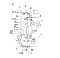
請求項69記載の発明は、図48に示すように、上記請求項67記載の熱搬送装置において、熱源側冷媒回路(A)を、冷媒加熱手段(11)、加熱熱交換手段(12)、膨張機構(18c)及び冷却熱交換手段(15)を冷媒の循環が可能に順に接続して成し、利用側手段(3)の暖房運転時、上記加熱熱交換手段(12)からの冷媒を冷却熱交換手段(15)をバイパスして冷媒加熱手段(11)に導く一方、利用側手段(3)の冷房運転時、上記冷媒加熱手段(11)からの冷媒を加熱熱交換手段(12)をバイパスして冷却熱交換手段(15)に導くバイパス路(17)が備えられ、該バイパス路(17)には、熱交換量調整手段(14)及び利用側手段(3)の暖房運転時に冷媒を減圧する減圧機構(18b)を設けた構成としている。
【0130】
請求項70記載の発明は、上記請求項69記載の熱搬送装置において、バイパス路(17)の一端を分岐させ、その一方を吸入側分岐管(16a)により冷媒加熱手段(11)の吸入側に、他方を吐出側分岐管(16b)により冷媒加熱手段(11)の吐出側に夫々接続させる。そして、上記吸入側分岐管(16a)に、利用側手段(3)の暖房運転時に開放し、冷房運転時に閉鎖する開閉弁(EVI)が、吐出側接続管(16b)には、利用側手段(3)の暖房運転時に閉鎖し、冷房運転時に開放する開閉弁(EVO)が夫々設けられた構成としている。
【0131】
これら請求項68〜70記載の発明では、上述した請求項67記載の作用を得るための熱源側冷媒回路(A)の構成を具体的に得ることができる。つまり、調整弁(18)により熱交換量調整手段(14)に流れる冷媒の流量を調整することにより、熱交換量調整手段(14)と熱源用冷媒との間の熱交換状態を変更して、熱源側冷媒回路(A)全体としての放熱量と吸熱量とが等しくされる。
【0132】
請求項71記載の発明は、上記請求項59〜62,67〜70の何れか1記載の熱搬送装置において、熱交換量調整手段(14)の着霜時、冷媒加熱手段(11)からの吐出冷媒を熱交換量調整手段(14)に供給して除霜する除霜手段(31)を設けた構成としている。
【0133】
この構成により、熱交換量調整手段(14)の着霜時には、除霜手段(31)が、冷媒加熱手段(11)からの吐出冷媒を熱交換量調整手段(14)に供給して除霜する。このため、熱交換量調整手段(14)の着霜を迅速に解消することができ、利用側手段(3)の放熱性能が向上される。
【0134】
請求項72記載の発明は、図47に示すように、上記請求項60または68記載の熱搬送装置において、熱交換量調整手段(14)の着霜時、冷媒加熱手段(11)からの吐出冷媒を熱交換量調整手段(14)に供給して除霜する除霜手段(31)を設け、該除霜手段(31)に、一端が冷媒加熱手段(11)の吐出側に、他端が熱交換量調整手段(14)に接続されたホットガス管(32)と、該ホットガス管(32)に設けられ、除霜運転時にのみ開放される開閉弁(EVD1)と、熱交換量調整手段(14)から膨張機構(13)を介して加熱熱交換手段(12)を経た冷媒を冷媒加熱手段(11)の吸入側に導く吸入管(33)と、該吸入管(33)に設けられ、除霜運転時にのみ開放される開閉弁(EVD2)とを備えさせた構成としている。
【0135】
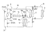
請求項73記載の発明は、図49に示すように、上記請求項61、62、69または70記載の熱搬送装置において、熱交換量調整手段(14)の着霜時、冷媒加熱手段(11)からの吐出冷媒を熱交換量調整手段(14)に供給して除霜する除霜手段(31)を設け、該除霜手段(31)に、冷媒加熱手段(11)と加熱熱交換手段(12)との間に設けられ、除霜運転時に閉鎖される開閉弁(EVD4)と、一端が上記開閉弁(EVD4)と加熱熱交換手段(12)との間に、他端が冷媒加熱手段(11)の吸入側に接続された接続管(33)と、該接続管(33)に設けられ、除霜運転時に閉鎖される開閉弁(EVD3)とを備えさせた構成としている。
【0136】
これら請求項72及び73記載の発明では、上述した請求項71記載の作用を得るための除霜手段(31)の構成を具体的に得ることができる。
【0137】
請求項74記載の発明は、上記請求項60〜62、64〜66、68〜70、71〜73の何れか1記載の熱搬送装置において、冷媒加熱手段を、圧縮機(11)としている。
【0138】
この構成により、冷媒加熱手段の具体構成を得ることができ、温熱源手段(1)に与える熱量を熱源側冷媒に確実に供給することができる。
【0139】
【発明の実施の形態】
次に、本発明の実施形態を図面に基いて説明する。また、本実施形態では、1次側及び2次側の2系統の冷媒回路を備え、1次側冷媒回路から2次側冷媒回路に与えられた熱量を利用して該2次側冷媒回路において冷媒を循環させながら室内の空気調和を行うようにした空気調和機の冷媒回路に本発明を適用した場合について説明する。
【0140】
(第1実施形態)
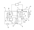
先ず、本発明の前提となる熱搬送装置の実施形態について図1及び図2を用いて説明する。本実施形態は、暖房専用の空気調和装置として上記1次側冷媒回路及び2次側冷媒回路を構成したものである。図1は、本形態に係る熱搬送装置全体の冷媒回路を示している。この図1に示すように、本冷媒回路は上述した熱源側冷媒回路としての1次側冷媒回路(A)の冷媒と2次側冷媒回路(B)の冷媒との間で熱交換が可能となっている。以下、各回路(A,B)について説明する。
【0141】
先ず、室内の空気との間で熱交換を行って室内の暖房を行う2次側冷媒回路(B)について説明する。この回路(B)は、温熱源手段としての温熱源熱交換器(1)と冷熱源手段としての冷熱源熱交換器(2)とが、ガス流通管(4)及び液流通管(5)によって接続されて、この温熱源熱交換器(1)と冷熱源熱交換器(2)との間で冷媒の循環が可能とされた閉回路を備えている。また、これら温熱源熱交換器(1)と冷熱源熱交換器(2)との設置状態は、冷熱源熱交換器(2)が温熱源熱交換器(1)よりも上方に配置されている。
【0142】
更に、この2次側冷媒回路(B)は、空気調和を行うための室内に設置された利用側手段としての室内熱交換器(3)が、ガス配管(6)を介してガス流通管(4)に、液配管(7)を介して液流通管(5)に夫々接続されている。
【0143】
また、上記ガス流通管(4)におけるガス配管(6)の接続位置と冷熱源熱交換器(2)との間にはガス流路切換え手段(8)を構成する開閉自在な電磁弁(EV1)が備えられている。そして、この電磁弁(EV1)は、切換え制御手段としてのコントローラ(C)によって、その開閉状態が切換え制御される。また、液流通管(5)における液配管(7)の接続位置と温熱源熱交換器(1)との間には、冷熱源熱交換器(2)から温熱源熱交換器(1)への液冷媒の流通のみを許容する第1逆止弁(CV1)が、液配管(7)には、室内熱交換器(3)から冷熱源熱交換器(2)への液冷媒の流通のみを許容する第2逆止弁(CV2)が夫々備えられている。このようにして液流路切換え手段(9)が構成されている。
【0144】
次に、2次側冷媒回路(B)に対して熱量を与える1次側冷媒回路(A)について説明する。この回路(A)は、冷媒加熱手段としての圧縮機(11)、上記温熱源熱交換器(1)との間で熱交換が可能とされた加熱熱交換手段としての加熱用熱交換器(12)、膨張機構としての膨張弁(13)、熱交換量調整手段としての熱量調整熱交換器(14)及び上記冷熱源熱交換器(2)との間で熱交換が可能とされた冷却熱交換手段としての冷却用熱交換器(15)が冷媒配管(16)により冷媒の循環が可能に順に接続されている。
【0145】
そして、上記膨張弁(13)及び熱量調整熱交換器(14)の間と、熱量調整熱交換器(14)及び冷却用熱交換器(15)の間とを接続するバイパス路(17)が備えられ、該バイパス路(17)には、熱量調整熱交換器(14)に流れる冷媒の流量を調整するように開度が変更される調整弁としての流量調整用電動弁(18)が設けられている。また、この流量調整用電動弁(18)は、上記コントローラ(C)によって開度が調整される。
【0146】
次に、上述の如く構成された本冷媒回路における室内の暖房運転時について説明する。尚、この運転状態の説明に用いる図2では、2次側冷媒回路(B)における各熱交換器(1,2,3)においてガス冷媒と液冷媒との貯留量の割合を示している。
【0147】
この暖房運転時には、先ず、コントローラ(C)によって、2次側冷媒回路(B)にあっては、電磁弁(EV1)が閉鎖される一方、1次側冷媒回路(A)にあっては、加熱用熱交換器(12)と温熱源熱交換器(1)との間での熱交換量と、冷却用熱交換器(15)と冷熱源熱交換器(2)との間での熱交換量との差に応じて熱量調整熱交換器(14)に流れる冷媒の流量を調整するように流量調整用電動弁(18)が開度調整される。
【0148】
具体的に各回路(A,B)における冷媒循環動作について説明すると、1次側冷媒回路(A)においては、圧縮機(11)から吐出された冷媒は、加熱用熱交換器(12)において温熱源熱交換器(1)との間で熱交換を行って凝縮し、膨張弁(13)において減圧され、その一部は熱量調整用熱交換器(14)において例えば外気との間で熱交換を行って蒸発する一方、他はバイパス路(17)を流れ冷却用熱交換器(15)において冷熱源熱交換器(2)との間で熱交換を行って蒸発し、これら蒸発したガス冷媒が圧縮機(11)に吸入されるといった循環動作を繰り返す。
【0149】
一方、2次側冷媒回路(B)にあっては、温熱源熱交換器(1)が加熱用熱交換器(12)から所定の熱量を受け、この温熱源熱交換器(1)では冷媒が蒸発して、該温熱源熱交換器(1)から高圧のガス冷媒が、図2(a)に示すように、ガス流通管(4)及びガス配管(6)を介して室内熱交換器(3)に供給される。そして、この室内熱交換器(3)においてガス冷媒が室内空気との間で熱交換して凝縮され室内空気を加温して室内を暖房する。また、この室内熱交換器(3)では冷媒が室温で凝縮されるのに対し、冷熱源熱交換器(2)では冷媒が冷却用熱交換器(15)の冷媒によって凝縮される。このため、室内熱交換器(3)の内圧は冷熱源熱交換器(2)よりも高くなっており、この圧力差によって、図2(b)に示すように室内熱交換器(3)の液冷媒は冷熱源熱交換器(2)に供給されることになる。つまり、この暖房運転に伴って冷熱源熱交換器(2)には液冷媒が貯留されていくことになる。また、この冷熱源熱交換器(2)にガス冷媒が導入された場合であっても、該冷熱源熱交換器(2)は冷却用熱交換器(15)により熱量が奪われているので、このガス冷媒は比較的低い温度で凝縮されることになる。
【0150】
そして、このような暖房運転が所定時間行われて、上記冷熱源熱交換器(2)における液冷媒の貯留量が所定量以上に達した時には、暖房運転が停止されて、液冷媒回収運転に切換えられる。この冷媒回収運転では、コントローラ(C)により、電磁弁(EV1)が開放される。これにより、図2(c)に示すように、ガス流通管(4)の高圧のガス冷媒が冷熱源熱交換器(2)に導入されることになり、これによって温熱源熱交換器(1)と冷熱源熱交換器(2)とが均圧される。そして、上述したように冷熱源熱交換器(2)は温熱源熱交換器(1)よりも上方に配置されているので、この高低差により冷熱源熱交換器(2)の液冷媒は温熱源熱交換器(1)に回収される。尚、液配管(7)には第2逆止弁(CV2)が設けられているので、この液冷媒回収運転時に、冷熱源熱交換器(2)の液冷媒が室内熱交換器(3)に流れ込むことはない。また、この液冷媒回収運転にあっては冷熱源熱交換器(2)では冷却用熱交換器(15)との間での熱交換を行わないようにしている。また、この際、温熱源熱交換器(1)での冷媒の加熱を行わないようにすれば、冷熱源熱交換器(2)との間で均圧される時間が短縮できるので、この液冷媒回収運転を迅速に完了できることになり、運転時間の短縮化を図ることができる。以上のような暖房運転と液冷媒回収運転とが交互に行われて、室内が暖房されることになる。
【0151】
そして、このような2次側冷媒回路(B)における暖房運転が行われている状態では、室内熱交換器(3)において冷媒が凝縮することから、加熱用熱交換器(12)から温熱源熱交換器(1)に与えられる熱量は、冷却用熱交換器(15)により冷熱源熱交換器(2)から奪われる熱量よりも大きくなっている。このため、1次側冷媒回路(A)全体としての放熱量と吸熱量とを等しくして該1次側冷媒回路(A)での冷媒の循環を良好に行わせるために、熱量調整熱交換器(14)における吸熱量を、上記の熱交換量の差分と等しくなるように、流量調整電動弁(18)の開度を設定して、熱量調整熱交換器(14)における冷媒流量を調整している。つまり、冷却用熱交換器(15)の吸熱量と熱量調整熱交換器(14)の吸熱量との和が、加熱用熱交換器(12)の放熱量に等しくなるように、流量調整電動弁(18)の開度が設定される。これにより、1次側冷媒回路(A)での冷媒の循環状態を良好に得ながら、2次側冷媒回路(B)での暖房運転が可能とされる。
【0152】
このように、本形態の熱搬送装置によれば、温熱源熱交換器(1)に与えられた熱量によって発生する冷媒の圧力上昇を利用して冷媒の循環動作を行わせるようにしているので、2次側冷媒回路(B)にポンプ等の駆動源を必要とせず、このため、消費電力の低減、故障発生要因箇所の削減、装置全体としての信頼性の確保を図ることができる。また、冷熱源熱交換器(2)において冷媒の凝縮を行っているのでガス冷媒を確実に液化することができ、この冷熱源熱交換器(2)の内圧の上昇が抑制でき、良好な冷媒の循環動作を行うことができる。このため、従来のように室内熱交換器からガス冷媒が流出しないように、該室内熱交換器において冷媒を過冷却状態にしておく必要がなくなり、冷媒と室内空気との間の熱交換量を十分に得ることができ、暖房能力の向上を図ることができ、また、機器の配設位置の制約が小さくできて高い信頼性及び汎用性を得ることができる。
【0153】
尚、本回路にあっては、上述した構成に限らず、第1及び第2逆止弁(CV1,CV2)を流量制御弁に夫々代えてもよい。
−2次側冷媒回路の変形例−
以下に、2次側冷媒回路(B)についての複数の変形例について説明する。尚、以下に説明する2次側冷媒回路(B)の変形例では、1次側冷媒回路についての説明及び図示を省略するが、上述した第1実施形態で説明した1次側冷媒回路(A)と同様の回路と組合せたり、後述する1次側冷媒回路の変形例で説明する回路と組合せることも可能である。また、以下の回路において同様の機能を有する部材については同一名称及び同一符号を付す。
【0154】
(第2実施形態)
本実施形態は、請求項6〜9記載の発明に係る形態であって、冷房専用の空気調和装置として2次側冷媒回路を構成したものである。また、本形態では、回路構成に関し、上述した第1実施形態との相違点についてのみ説明する。
【0155】
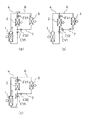
図3に示すように、ガス流通管(4)におけるガス配管(6)の接続位置と温熱源熱交換器(1)との間にはガス冷媒用電磁弁(EV1)が設けられ、ガス配管(6)には、室内熱交換器(3)から冷熱源熱交換器(2)へのガス冷媒の流通のみを許容するガス冷媒用逆止弁(CVG)が設けられている。これによりガス流路切換え手段(8)が構成されている。
【0156】
また、液流通管(5)における液配管(7)の接続位置と温熱源熱交換器(1)との間には、上述した第1実施形態と同様の第1逆止弁(CV1)の他に液冷媒用電磁弁(EV4)が備えられている。また、液配管(7)には、冷熱源熱交換器(2)から室内熱交換器(3)への液冷媒の流通のみを許容する請求項9記載の発明でいう第2の逆止弁としての第3逆止弁(CV3)が備えられている。これにより液流路切換え手段(9)が構成されている。そして、上記各電磁弁(EV1,EV4)がコントローラ(C)によって開閉制御されるようになっている。
【0157】
次に、上述の如く構成された本冷媒回路(B)における室内の冷房運転時について説明する。この冷房運転開始前には、予め冷熱源熱交換器(2)に液冷媒が貯留されている。この状態から冷房運転が開始されると、先ず、コントローラ(C)によってガス冷媒用電磁弁(EV1)が開放され且つ液冷媒用電磁弁(EV4)が閉鎖される。この状態で、図4(a)に示すように、温熱源熱交換器(1)からの高圧のガス冷媒がガス流通管(4)を介して冷熱源熱交換器(2)に供給される。すると、この圧力の作用により、予め冷熱源熱交換器(2)に貯留されていた液冷媒は、図4(b)に示すように、液流通管(5)及び液配管(7)を介して室内熱交換器(3)に向って押出される。また、この図4(a),(b)に示す状態では冷熱源熱交換器(2)における放熱は行われない。
【0158】
そして、このような状態が所定時間継続して行われた後、コントローラ(C)によってガス冷媒用電磁弁(EV1)が閉鎖される。この状態では、温熱源熱交換器(1)から冷熱源熱交換器(2)へのガス冷媒の供給は停止される。そして、冷熱源熱交換器(2)にガス冷媒が室内熱交換器(3)に液冷媒が夫々導入された状態において、冷熱源熱交換器(2)においてガス冷媒が凝縮され、この凝縮に伴う圧力降下により該冷熱源熱交換器(2)の内圧が室内熱交換器(3)よりも低くなり、この圧力差によって図4(c)に示すように室内熱交換器(3)で蒸発する冷媒は冷熱源熱交換器(2)に導入されることになる。つまり、室内熱交換器(3)では冷媒と室内空気との間で熱交換が行われて室内空気が冷却される。
【0159】
このような冷房運転が所定時間行われて、温熱源熱交換器(1)の液冷媒の貯留量が所定量以下に達した時には、冷房運転が停止されて、液冷媒回収運転に切換えられる。この冷媒回収運転では、コントローラ(C)により、各電磁弁(EV1,EV4)が共に開放される。これにより、上述した第1実施形態の場合と同様に、温熱源熱交換器(1)と冷熱源熱交換器(2)とが均圧され、冷熱源熱交換器(2)の液冷媒が温熱源熱交換器(1)に回収される。尚、ガス配管(6)にはガス冷媒用逆止弁(CVG)が設けられていることにより、この液冷媒回収運転時に、温熱源熱交換器(2)からのガス冷媒が室内熱交換器(3)に流れ込むことはない。また、この液冷媒回収運転にあっては冷熱源熱交換器(2)では冷却用熱交換器(15)との間での熱交換を行わないようにしている。以上のような冷房運転と液冷媒回収運転とが交互に行われて、室内が冷房されることになる。
【0160】
このように、本形態の熱搬送装置によっても、2次側冷媒回路(B)にポンプ等の駆動源を備えさせる必要がなく、消費電力の低減、故障発生要因箇所の削減、装置全体としての信頼性の確保を図ることができる。
【0161】
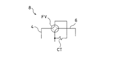
尚、本回路にあっては、上述した構成に限らず、ガス冷媒用逆止弁(CVG)に代えて、流量制御弁を備えさせるようにしてもよい。また、第1逆止弁(CV1)及び液冷媒用電磁弁(EV4)のうち一方のみを備えさせる構成としてもよい。また、ガス流路切換え手段(8)として、ガス冷媒用電磁弁(EV1)及びガス冷媒用逆止弁(CVG)に代えて、図5に示すように四路切換弁(FV)及びキャピラリチューブ(CT)を備えさせる構成とし、冷媒の循環状態に応じて四路切換弁(FV)を切換えるようにしてもよい。つまり、冷熱源熱交換器(2)から室内熱交換器(3)に液冷媒を供給する際には、図5に破線で示すように四路切換弁(FV)を切換え、室内熱交換器(3)から冷熱源熱交換器(2)にガス冷媒を供給する際には、図5に実線で示すように四路切換弁(FV)を切換える。更に、液流路切換え手段(9)の構成として、図6に示すように、第1逆止弁(CV1)の位置を、液流通管(5)に対する液配管(7)の接続位置と冷熱源熱交換器(2)との間に設定すれば、第3逆止弁(CV3)を廃止することができる。
【0162】
(第3実施形態)
次に、請求項10〜13記載の発明に係る熱搬送装置の実施形態について図面に基いて説明する。本実施形態は、暖房運転と冷房運転とが切換え可能な空気調和装置として2次側冷媒回路を構成したものである。また、本形態では、回路構成に関して上述した各実施形態との相違点についてのみ説明する。
【0163】
図7に示すように、ガス流通管(4)におけるガス配管(6)の接続位置と冷熱源熱交換器(2)との間に第1電磁弁(EV1)が設けられ、ガス配管(6)に第2電磁弁(EV2)が設けられ、上記第1電磁弁(EV1)及び冷熱源熱交換器(2)の間と第2電磁弁(EV2)及び室内熱交換器(3)の間とを接続する接続管(10)には第3電磁弁(EV3)が設けられ、更に、この接続管(10)には室内熱交換器(3)から冷熱源熱交換器(2)へのガス冷媒の流通のみを許容するガス冷媒用逆止弁(CVG)が設けられている。このようにしてガス流路切換え手段(8)が構成されている。
【0164】
また、液流通管(5)における液配管(7)の接続位置と温熱源熱交換器(1)との間には請求項13記載の発明でいう第1の開閉弁としての第4電磁弁(EV4)が設けられ、更に、この部分には冷熱源熱交換器(2)から温熱源熱交換器(1)への液冷媒の流通のみを許容する液冷媒用逆止弁(CVL)が設けられ、液配管(7)には請求項13記載の発明でいう第2の開閉弁としての第5電動弁(EV5)が設けられている。このようにして液流路切換え手段(9)が構成されている。そして、上記各電磁弁(EV1,EV2,EV3,EV4)及び電動弁(EV5)がコントローラ(C)によって開閉状態が切換え制御されるようになっている。
【0165】
次に、上述の如く構成された本冷媒回路(B)における室内の暖房運転時及び冷房運転時について説明する。先ず、暖房運転時について説明する。この暖房運転時には、先ず、コントローラ(C)によって第1電磁弁(EV1)及び第3電磁弁(EV3)が閉鎖されると共に、第2電磁弁(EV2)、第4電磁弁(EV4)及び第5電動弁(EV5)が開放される。この状態で、上述した第1実施形態の場合と同様に、図8(a)の如く、温熱源熱交換器(1)からのガス冷媒が、室内熱交換器(3)に供給されて、凝縮され、室内空気を加温し、その後、この凝縮された液冷媒は、図8(b)に示すように、室内熱交換器(3)と冷熱源熱交換器(2)との圧力差によって該冷熱源熱交換器(2)に供給されることになる。
【0166】
そして、上記冷熱源熱交換器(2)における液冷媒の貯留量が所定量以上に達した時には、暖房運転が停止されて、上述した第1実施形態と同様の液冷媒回収運転に切換えられる。この液冷媒回収運転時には、コントローラ(C)によって第2電磁弁(EV2)、第3電磁弁(EV3)及び第5電動弁(EV5)が閉鎖されると共に、第1電磁弁(EV1)及び第4電磁弁(EV4)が開放される。この状態で、図8(c)に示すように、ガス流通管(4)の高圧のガス冷媒が冷熱源熱交換器(2)に導入されることになり、これによって温熱源熱交換器(1)と冷熱源熱交換器(2)とが均圧されて、この両熱交換器(1,2)の高低差により冷熱源熱交換器(2)の液冷媒は温熱源熱交換器(1)に回収される。
【0167】
次に、冷房運転時について図9を用いて説明する。この冷房運転時には、先ず、コントローラ(C)によって第2電磁弁(EV2)及び第4電磁弁(EV4)が閉鎖されると共に、第1電磁弁(EV1)、第3電磁弁(EV3)及び第5電動弁(EV5)が開放される。この状態で、上述した第2実施形態の場合と同様に、図9(a)に示すように、温熱源熱交換器(1)からの高圧のガス冷媒がガス流通管(4)を介して冷熱源熱交換器(2)に供給され、予め冷熱源熱交換器(2)に貯留されていた液冷媒は、図9(b)に示すように、液流通管(5)及び液配管(7)を介して室内熱交換器(3)に向って押出される。
【0168】
そして、このような状態が所定時間継続して行われた後、コントローラ(C)によって第1電磁弁(EV1)が閉鎖され、冷媒が凝縮する冷熱源熱交換器(2)と冷媒が蒸発する室内熱交換器(3)との圧力差によって、図9(c)に示すように、室内熱交換器(3)の冷媒は接続管(10)を経て冷熱源熱交換器(2)に供給されることになる。
【0169】
そして、このような冷房運転が所定時間行われて、温熱源熱交換器(1)の液冷媒の貯留量が所定量以下に達した時には、冷房運転が停止されて、液冷媒回収運転に切換えられる。この冷媒回収運転では、コントローラ(C)により、第1電磁弁(EV1)及び第4電磁弁(EV4)が共に開放される。これにより、温熱源熱交換器(1)と冷熱源熱交換器(2)とが均圧され、冷熱源熱交換器(2)の液冷媒が温熱源熱交換器(1)に回収される。
【0170】
尚、本回路にあっては、上述した構成に限らず、液冷媒用逆止弁(CVL)及び第4電磁弁(EV4)に代えて、流量制御弁を備えさせるようにしてもよい。また、ガス流路切換え手段(8)を、図10に示すように第1電磁弁(EV1)、ガス冷媒用逆止弁(CVG)、四路切換弁(FV)及びキャピラリチューブ(CT)を備えさせる構成とし、冷媒の循環状態に応じて四路切換弁(FV)を切換えるようにしてもよい。つまり、暖房運転時には、図10に破線で示すように四路切換弁(FV)を切換え、冷房運転時及び冷熱源熱交換器(2)から温熱源熱交換器(1)への液冷媒回収時には、図10に実線で示すように四路切換弁(FV)を切換える。更に、第5電動弁(EV5)に代えて、図11に示すように、液配管(7)の一部を分岐し、夫々に電磁弁(EV5',EV5'')及び互いに逆方向の液冷媒の流通を許容する逆止弁(CVL',CVL'')を備えさせ、暖房運転時には、室内熱交換器(3)から冷熱源熱交換器(2)への液冷媒の流通を許容する逆止弁(CVL')に直列に接続された電磁弁(EV5')を開放し、冷房運転時には、冷熱源熱交換器(2)から室内熱交換器(3)への液冷媒の流通を許容する逆止弁(CVL'')に直列に接続された電磁弁(EV5'')を開放するようにしてもよい。
【0171】
(第4実施形態)
次に、請求項14〜20記載の発明に係る熱搬送装置の実施形態について図面に基いて説明する。本実施形態は、複数の室内の個々に配置された複数の室内熱交換器を備え、夫々が個別に冷房運転と暖房運転とを選択可能とされた所謂冷暖フリーのマルチ型空気調和装置として2次側冷媒回路を構成したものである。
【0172】
図12に示すように、ガス流通管(4)におけるガス配管(6)の接続位置と冷熱源熱交換器(2)との間に第1電磁弁(EV1)が設けられており、ガス配管(6)における各室内熱交換器(3a〜3d)側は複数に分岐されて夫々が分岐ガス配管(6a〜6d)に構成されており、各分岐ガス配管(6a〜6d)には第2電磁弁(EV2-1〜EV2-4)が設けられている。また、上記第1電磁弁(EV1)及び冷熱源熱交換器(2)の間と第2電磁弁(EV2-1〜EV2-4)及び室内熱交換器(3a〜3d)の間とは接続管(10)により接続されている。この接続管(10)は、各室内熱交換器(3a〜3d)側が複数に分岐されて夫々が分岐接続管(10a〜10d)に構成されており、各分岐接続管(10a〜10d)には第3電磁弁(EV3-1〜EV3-4)が夫々設けられている。また、接続管(10)には、各室内熱交換器(3a〜3d)から冷熱源熱交換器(2)へのガス冷媒の流通のみを許容するガス冷媒用逆止弁(CVG)が設けられている。このようにしてガス流路切換え手段(8)が構成されている。
【0173】
一方、液流通管(5)における液配管(7)の接続位置と温熱源熱交換器(1)との間には、請求項20記載の発明でいう第1の開閉弁としての第4電磁弁(EV4)が設けられ、更に、液流通管(5)には冷熱源熱交換器(2)から温熱源熱交換器(1)への液冷媒の流通のみを許容する液冷媒用逆止弁(CVL)が設けられている。また、液配管(7)は、各室内熱交換器(3a〜3d)側が複数に分岐されて夫々が分岐液配管(7a〜7d)に構成されており、各分岐液配管(7a〜7d)には請求項20記載の発明でいう第2の開閉弁としての第5電動弁(EV5-1〜EV5-4)が夫々設けられている。
【0174】
次に、上述の如く構成された本冷媒回路(B)における各室内の空調運転時について説明する。この空調運転状態としては、各室内が共に暖房される状態、つまり全ての室内熱交換器(3a〜3d)が共に放熱運転を行う状態、各室内が共に冷房される状態、つまり全ての室内熱交換器(3a〜3d)が共に吸熱運転を行う状態、一部の室内が暖房され他部の室内が冷房される状態、つまり一部の室内熱交換器が放熱運転を行い、他の室内熱交換器が吸熱運転を行う状態とに分けられる。更に、一部の室内が暖房され他の室内が冷房される状態としては、各室全体の熱の収支が暖房要求である場合(例えば、吸熱運転する室内熱交換器よりも放熱運転する室内熱交換器が多い場合)、冷房要求である場合(例えば、放熱運転する室内熱交換器よりも吸熱運転する室内熱交換器が多い場合)、これらが同一である場合(例えば、吸熱運転する室内熱交換器と放熱運転する室内熱交換器とが同数である場合)とに分けられる。以下、各場合について夫々説明する。
【0175】
先ず、全ての室内熱交換器(3a〜3d)が共に放熱運転を行う場合について図13を用いて説明する。この運転時には、先ず、コントローラ(C)によって第1電磁弁(EV1)及び各第3電磁弁(EV3-1〜EV3-4)が閉鎖されると共に、各第2電磁弁(EV2-1〜EV2-4)、第4電磁弁(EV4)及び各第5電動弁(EV5-1〜EV5-4)が開放される。この状態で、図13(a)に示すように、上述した第1実施形態の場合と同様に、温熱源熱交換器(1)からのガス冷媒が、各分岐ガス配管(6a〜6d)を経て各室内熱交換器(3a〜3d)に供給されて凝縮され、各室内の空気を加温し、その後、この凝縮された液冷媒は、図13(b)に示すように、室内熱交換器(3a〜3d)と冷熱源熱交換器(2)との圧力差によって各分岐液配管(7a〜7d)を経て冷熱源熱交換器(2)に供給されることになる。
【0176】
そして、上記冷熱源熱交換器(2)における液冷媒の貯留量が所定量以上に達した時には、暖房運転が停止されて、上述した第1実施形態と同様の液冷媒回収運転に切換えられる。この液冷媒回収運転時には、コントローラ(C)によって各第2電磁弁(EV2-1〜EV2-4)、第3電磁弁(EV3-1〜EV3-4)及び第5電動弁(EV5-1〜EV5-4)が閉鎖されると共に、第1電磁弁(EV1)及び第4電磁弁(EV4)が開放される。この状態で、図13(c)に示すように、ガス流通管(4)の高圧のガス冷媒が冷熱源熱交換器(2)に導入されることになり、これによって温熱源熱交換器(1)と冷熱源熱交換器(2)とが均圧されて、この各熱交換器(1,2)の高低差により冷熱源熱交換器(2)の液冷媒は温熱源熱交換器(1)に回収される。
【0177】
次に、全ての室内熱交換器(3a〜3d)が共に吸熱運転を行う場合について図14を用いて説明する。この運転時には、先ず、コントローラ(C)によって各第2電磁弁(EV2-1〜EV2-4)及び第4電磁弁(EV4)が閉鎖されると共に、第1電磁弁(EV1)、第3電磁弁(EV3-1〜EV3-4)及び第5電動弁(EV5-1〜EV5-4)が開放される。この状態で、上述した第2実施形態の場合と同様に、図14(a)に示すように、温熱源熱交換器(1)からの高圧のガス冷媒がガス流通管(4)を介して冷熱源熱交換器(2)に供給され、予め冷熱源熱交換器(2)に貯留されていた液冷媒は、図14(b)に示すように、各分岐液配管(7a〜7d)を介して室内熱交換器(3a〜3d)に導入される。
【0178】
そして、このような状態が所定時間継続して行われた後、コントローラ(C)によって第1電磁弁(EV1)が閉鎖され、冷媒が凝縮する冷熱源熱交換器(2)と冷媒が蒸発する各室内熱交換器(3a〜3d)との圧力差によって、図14(c)に示すように、各室内熱交換器(3a〜3d)の液冷媒は分岐接続管(10a〜10d)を経て冷熱源熱交換器(2)に供給されることになる。
【0179】
そして、このような冷房運転が所定時間行われて、温熱源熱交換器(1)の液冷媒の貯留量が所定量以下に達した時には、冷房運転が停止されて、液冷媒回収運転に切換えられる。この冷媒回収運転では、コントローラ(C)により、第1電磁弁(EV1)及び第4電磁弁(EV4)が共に開放される。これにより、温熱源熱交換器(1)と冷熱源熱交換器(2)とが均圧され、冷熱源熱交換器(2)の液冷媒が温熱源熱交換器(1)に回収される。
【0180】
次に、各室全体の熱の収支が暖房要求である場合、つまり、吸熱運転する室内熱交換器よりも放熱運転する室内熱交換器が多い場合について図15を用いて説明する。尚、ここでは、図15における4台の室内熱交換器(3a〜3d)のうち最も右側に位置する室内熱交換器(3d)のみが吸熱運転し、その他の室内熱交換器(3a〜3c)が放熱運転する場合を例に挙げて説明する。この運転時には、先ず、コントローラ(C)によって第1電磁弁(EV1)、放熱運転する室内熱交換器(3a〜3c)に繋る3個の第3電磁弁(EV3-1〜EV3-3)及び吸熱運転する室内熱交換器(3d)に繋る1個の第2電磁弁(EV2-4)が閉鎖されると共に、放熱運転する室内熱交換器(3a〜3c)に繋る3個の第2電磁弁(EV2-1〜EV2-3)、第4電磁弁(EV4)、各第5電動弁(EV5-1〜EV5-4)及び吸熱運転する室内熱交換器(3d)に繋る1個の第3電磁弁(EV3-4)が開放される。この状態で、温熱源熱交換器(1)からのガス冷媒が、図15(a)に示すように、各分岐ガス配管(6a〜6c)を経て放熱運転する室内熱交換器(3a〜3c)に供給されて凝縮され、各室内の空気を加温してこの室内を暖房し、その後、この凝縮された液冷媒は、図15(b)に示すように、放熱運転する室内熱交換器(3a〜3c)と冷熱源熱交換器(2)及び吸熱運転する室内熱交換器(3d)との圧力差によって各分岐液配管(7a〜7c)を経て冷熱源熱交換器(2)だけでなく分岐液配管(7d)を経て吸熱運転する室内熱交換器(3d)に所定の分配比率で分配供給され、この室内熱交換器(3d)において蒸発して室内を冷房することになる。また、この室内熱交換器(3d)において蒸発したガス冷媒は分岐接続管(10d)を経て冷熱源熱交換器(2)に供給され、該冷熱源熱交換器(2)において凝縮される。
【0181】
そして、上記冷熱源熱交換器(2)における液冷媒の貯留量が所定量以上に達した時には、暖房運転が停止されて、液冷媒回収運転に切換えられる。この液冷媒回収運転時には、コントローラ(C)によって各第2電磁弁(EV2-1〜EV2-4)、第3電磁弁(EV3-1〜EV3-4)及び第5電動弁(EV5-1〜EV5-4)が閉鎖されると共に、第1電磁弁(EV1)及び第4電磁弁(EV4)が開放される。この状態で、図15(c)に示すように、ガス流通管(4)の高圧のガス冷媒が冷熱源熱交換器(2)に導入されることになり、これによって温熱源熱交換器(1)と冷熱源熱交換器(2)とが均圧されて、この各熱交換器(1,2)の高低差により冷熱源熱交換器(2)の液冷媒は温熱源熱交換器(1)に回収される。
【0182】
次に、各室全体の熱の収支が冷房要求である場合、つまり、放熱運転する室内熱交換器よりも吸熱運転する室内熱交換器が多い場合について図16を用いて説明する。尚、ここでは、図16における4台の室内熱交換器(3a〜3d)のうち最も左側に位置する室内熱交換器(3a)のみが放熱運転し、その他の室内熱交換器(3b〜3d)が吸熱運転する場合を例に挙げて説明する。この運転時には、先ず、コントローラ(C)によって各第2電磁弁(EV2-1〜EV2-4)、第4電磁弁(EV4)、放熱運転する室内熱交換器(3a)に繋る第3電磁弁(EV3-1)及び放熱運転する室内熱交換器(3a)に繋る第5電動弁(EV5-1)が閉鎖されると共に、第1電磁弁(EV1)、吸熱運転する室内熱交換器(3b〜3d)に繋る第3電磁弁(EV3-2〜EV3-4)及び吸熱運転する室内熱交換器(3b〜3d)に繋る第5電動弁(EV5-2〜EV5-4)が開放される。この状態で、図16(a)に示すように、温熱源熱交換器(1)からの高圧のガス冷媒がガス流通管(4)を介して冷熱源熱交換器(2)に供給され、予め冷熱源熱交換器(2)に貯留されていた液冷媒は、図16(b)に示すように、各分岐液配管(7b〜7d)を介して吸熱運転する室内熱交換器(3b〜3d)に導入される。その後、放熱運転する室内熱交換器(3a)に繋る第2電磁弁(EV2-1)及び放熱運転する室内熱交換器(3a)に繋る第5電磁弁(EV5-1)が開放される一方、第1電磁弁(EV1)が閉鎖され、図16(c)に示すように、吸熱運転する室内熱交換器(3b〜3d)において蒸発したガス冷媒は分岐接続管(10b〜10d)を経て冷熱源熱交換器(2)に供給され、該冷熱源熱交換器(2)において凝縮される。また、温熱源熱交換器(1)からのガス冷媒は放熱運転する室内熱交換器(3a)に供給されて該室内熱交換器(3a)で凝縮して室内を暖房した後、分岐液配管(7a)を経て冷熱源熱交換器(2)に供給される。
【0183】
そして、このような空調運転が所定時間行われて、温熱源熱交換器(1)の液冷媒の貯留量が所定量以下に達した時には、空調運転が停止されて、液冷媒回収運転に切換えられる。この冷媒回収運転では、コントローラ(C)により、第1電磁弁(EV1)及び第4電磁弁(EV4)が共に開放される。これにより、温熱源熱交換器(1)と冷熱源熱交換器(2)とが均圧され、冷熱源熱交換器(2)の液冷媒が温熱源熱交換器(1)に回収される。
【0184】
次に、各室内熱交換器における放熱量と吸熱量とが同一である場合、つまり、吸熱運転する室内熱交換器と放熱運転する室内熱交換器とが同数である場合について図17を用いて説明する。尚、ここでは、図17における4台の室内熱交換器(3a〜3d)のうち右側に位置する2台の室内熱交換器(3c,3d)が吸熱運転し、左側に位置する2台の室内熱交換器(3a,3b)が放熱運転する場合を例に挙げて説明する。この運転時には、先ず、コントローラ(C)によって第1電磁弁(EV1)、放熱運転する室内熱交換器(3a,3b)に繋る2個の第3電磁弁(EV3-1,EV3-2)及び吸熱運転する室内熱交換器(3c,3d)に繋る2個の第2電磁弁(EV2-3,EV2-4)が閉鎖されると共に、放熱運転する室内熱交換器(3a,3b)に繋る2個の第2電磁弁(EV2-1,EV2-2)、第4電磁弁(EV4)、各第5電動弁(EV5-1〜EV5-4)及び吸熱運転する室内熱交換器(3c,3d)に繋る2個の第3電磁弁(EV3-3,EV3-4)が開放される。この状態で、温熱源熱交換器(1)からのガス冷媒が、図17(a)に示すように、各分岐ガス配管(6a,6b)を経て放熱運転する室内熱交換器(3a,3b)に供給されて、凝縮され、各室内の空気を加温してこの室内を暖房し、その後、この凝縮された液冷媒は、図17(b)に示すように、放熱運転する室内熱交換器(3a,3b)と冷熱源熱交換器(2)及び吸熱運転する室内熱交換器(3c,3d)との圧力差によって各分岐液配管(7a,7b)を経て冷熱源熱交換器(2)及び吸熱運転する室内熱交換器(3c,3d)に所定の分配比率で分配供給され、この室内熱交換器(3c,3d)において蒸発して室内を冷房することになる。また、この室内熱交換器(3c,3d)において蒸発したガス冷媒は分岐接続管(10c,10d)を経て冷熱源熱交換器(2)に供給され、該冷熱源熱交換器(2)において凝縮される。
【0185】
そして、上記冷熱源熱交換器(2)における液冷媒の貯留量が所定量以上に達した時には、空調運転が停止されて、液冷媒回収運転に切換えられる。この液冷媒回収運転時には、コントローラ(C)によって各第2電磁弁(EV2-1〜EV2-4)、第3電磁弁(EV3-1〜EV3-4)及び第5電動弁(EV5-1〜EV5-4)が閉鎖されると共に、第1電磁弁(EV1)及び第4電磁弁(EV4)が開放される。この状態で、図17(c)に示すように、ガス流通管(4)の高圧のガス冷媒が冷熱源熱交換器(2)に導入されることになり、これによって温熱源熱交換器(1)と冷熱源熱交換器(2)とが均圧されて、この高低差により冷熱源熱交換器(2)の液冷媒は温熱源熱交換器(1)に回収される。
−変形例−
次に上述した第1〜第4の実施形態の変形例として請求項1〜5および請求項21,22記載の発明に係る実施形態について説明する。本変形例は、冷熱源熱交換器(2)周辺部の冷媒回路を変形したものであって、上記各実施形態の何れに適用した場合も同様の構成であるので、ここでは、第1実施形態及び第2実施形態に夫々適用した場合について説明する。図18は第1実施形態(暖房専用の装置)に適用した場合を示しており、液冷媒を貯留可能な受液手段としての受液器(22)が、一端がガス流通管(4)に、他端が液流通管(5)に夫々分岐接続された分岐管(23)を介して冷熱源熱交換器(2)に並列に接続されている。また、ガス流通管(4)における分岐管(23)との接続部分と冷熱源熱交換器(2)との間には電磁弁(EV11)が設けられている一方、液流通管(5)における分岐管(23)との接続部分と冷熱源熱交換器(2)との間には、液流通管(5)から分岐管(23)への冷媒の流通のみを許容する逆止弁(CV5)が設けられている。その他の構成は上述した第1実施形態と同様である。
【0186】
このような構成における暖房運転動作を図19を用いて説明すると、先ず、電磁弁(EV1)を閉鎖すると共に電磁弁(EV11)を開放し、温熱源熱交換器(1)から室内熱交換器(3)に供給されたガス冷媒を、該室内熱交換器(3)において凝縮させる(図19(a))。そして、この室内熱交換器(3)での凝縮温度よりも低い凝縮温度で冷媒を凝縮する冷熱源熱交換器(2)と該冷熱源熱交換器(2)に電磁弁(EV11)を介して接続されている受液器(22)とでは室内熱交換器(3)よりも低圧になっているために、この室内熱交換器(3)において凝縮された液冷媒は液配管(7)から分岐管(23)に導入されて受液器(22)に貯留される。この際、受液器(22)に導入されていたガス冷媒は電磁弁(EV11)を経て冷熱源熱交換器(2)に導入され、該冷熱源熱交換器(2)において凝縮され(図19(b))、この凝縮された液冷媒は冷熱源熱交換器(2)から受液器(22)に回収されることになる。そして、この受液器(22)での液冷媒の貯留量が所定量を越えた状態になると、電磁弁(EV1)を開放すると共に電磁弁(EV11)を閉鎖し、上述と同様の液冷媒回収運転を行う(図19(c))。
【0187】
このような動作であるために、運転中に冷熱源熱交換器(2)に貯留される液冷媒の量を低減でき、該冷熱源熱交換器(2)の熱交換面積を十分に確保することができることになる。これにより、冷熱源熱交換器(2)の小型化を図ることができ、装置全体のコンパクトにできる。
【0188】
また、図20は第2実施形態(冷房専用の装置)に適用した場合の冷房運転動作を示している。この冷房運転時では、先ず、電磁弁(EV1)を開放すると共に電磁弁(EV11)を閉鎖し、温熱源熱交換器(1)からの高圧のガス冷媒を受液器(22)に供給して(図20(a))、予め受液器(22)に貯留されていた液冷媒を、室内熱交換器(3)に導入する(図20(b))。その後、電磁弁(EV1)を閉鎖すると共に電磁弁(EV11)を開放する。これにより、室内熱交換器(3)に導入されたガス冷媒は、冷熱源熱交換器(2)での冷媒の凝縮に伴って減圧され蒸発した後、この室内熱交換器(3)と冷熱源熱交換器(2)との差圧により冷熱源熱交換器(2)に導入され、該冷熱源熱交換器(2)で凝縮されて液化した後、受液器(22)に回収されることになる(図20(c))。従って、この動作によっても運転中に冷熱源熱交換器(2)に貯留される液冷媒の量を低減でき、冷熱源熱交換器(2)の小型化を図ることができる。
【0189】
また、本変形例の構成では、液冷媒を冷熱源熱交換器(2)や受液器(22)から排出する際に電磁弁(EV1)を閉鎖していることにより、温熱源熱交換器(1)からのガス冷媒が冷熱源熱交換器(2)に供給されて該冷熱源熱交換器(2)が不必要に加熱されるといった状況が回避されるので省エネルギ性の向上を図ることができる。また、逆止弁(CV5)を設けたことで、受液器(22)の液冷媒が冷熱源熱交換器(2)に逆流することはなく、これによっても省エネルギ性の向上が図れる。
【0190】
尚、本形態の構成を上述した第4実施形態のように複数の室内熱交換器(3a〜3d)を備えた装置に適用する場合には、各室内熱交換器(3a〜3d)夫々に対して受液器(22)を並列に接続させる。
−複数の冷熱源熱交換器を備えた変形例−
以下に述べる第5〜第8実施形態は、冷熱源熱交換器を複数台(本形態では2台)備えさせた構成である。
【0191】
(第5実施形態)
本形態は、請求項24〜26記載の発明に係る実施形態であり、第1及び第2の2台の冷熱源熱交換器を備えたものであって、暖房専用の空気調和装置として2次側冷媒回路を構成したものである。図21に示すように、ガス流通管(4)は冷熱源熱交換器側が分岐されて第1及び第2の分岐ガス流通管(4a,4b)に形成されており、第1分岐ガス流通管(4a)が第1冷熱源熱交換器(2a)に、第2分岐ガス流通管(4b)が第2冷熱源熱交換器(2b)に夫々接続されている。そして、各分岐ガス流通管(4a,4b)にはガス配管(6)が接続され、この各分岐ガス流通管(4a,4b)には電磁弁(EV1-1,EV1-2)が設けられている。この電磁弁(EV1-1,EV1-2)はコントローラ(C)によって開閉制御される。
【0192】
また、液流通管(5)も冷熱源熱交換器側が分岐されて第1及び第2の分岐液流通管(5a,5b)に形成されており、第1分岐液流通管(5a)が第1冷熱源熱交換器(2a)に、第2分岐液流通管(5b)が第2冷熱源熱交換器(2b)に夫々接続されている。更に、液配管(7)における液流通管(5)との接続側も分岐されて第1及び第2の分岐液配管(7e,7f)に構成されており、第1分岐液配管(7e)が第1分岐液流通管(5a)に、第2分岐液配管(7f)が第2分岐液流通管(5b)に夫々接続されている。
【0193】
そして、この分岐液流通管(5a,5b)に対する分岐液配管(7e,7f)の接続位置と温熱源熱交換器(1)との間には冷熱源熱交換器(2)から温熱源熱交換器(1)への液冷媒の流通のみを許容する第1逆止弁(CV1-1,CV1-2)が夫々設けられ、上記各分岐液配管(7e,7f)には室内熱交換器(3)から冷熱源熱交換器(2a,2b)への液冷媒の流通のみを許容する第2逆止弁(CV2-1,CV2-2)が夫々設けられている。
【0194】
次に、上述の如く構成された本2次側冷媒回路(B)における室内の暖房運転時について説明する。この暖房運転時には、先ず、コントローラ(C)によって第1分岐ガス流通管(4a)の電磁弁(EV1-1)が開放される一方、第2分岐ガス流通管(4b)の電磁弁(EV1-2)が閉鎖される。この状態で、温熱源熱交換器(1)が1次側冷媒回路からの熱量を受け、温熱源熱交換器(1)では冷媒が蒸発して、図22(a)に示すように、温熱源熱交換器(1)から高圧のガス冷媒は、その一部が第1分岐ガス流通管(4a)を経て第1冷熱源熱交換器(2a)に、他がガス配管(6)を経て室内熱交換器(3)に供給される。そして、この室内熱交換器(3)においてガス冷媒が室内空気との間で熱交換して凝縮され室内空気を加温して室内を暖房する。そして、この状態では、室内熱交換器(3)と第2冷熱源熱交換器(2b)との圧力差によって、図22(b)に示すように、室内熱交換器(3)の液冷媒は第2分岐液配管(7f)を経て第2冷熱源熱交換器(2b)に供給されることになる。つまり、この暖房運転に伴って第2冷熱源熱交換器(2b)には液冷媒が貯留されていくことになる。一方、第1冷熱源熱交換器(2a)にあっては温熱源熱交換器(1)からガス冷媒が供給されていることにより、この第1冷熱源熱交換器(2a)の液冷媒は第1分岐液流通管(5a)から温熱源熱交換器(1)に回収されている。
【0195】
そして、このような暖房運転が所定時間行われて、上記第2冷熱源熱交換器(2b)における液冷媒の貯留量が所定量以上に達した時には、コントローラ(C)によって第2分岐ガス流通管(4b)の電磁弁(EV1-2)が開放される一方、第1分岐ガス流通管(4a)の電磁弁(EV1-1)が閉鎖される。これにより、温熱源熱交換器(1)から高圧のガス冷媒は、図22(c)に示すように、その一部が第2分岐ガス流通管(4b)を経て第2冷熱源熱交換器(2b)に、他がガス配管(6)を経て室内熱交換器(3)に供給される。そして、この室内熱交換器(3)においてガス冷媒が室内空気との間で熱交換して凝縮され室内空気を加温して室内を暖房する。そして、この状態では、室内熱交換器(3)と第1冷熱源熱交換器(2a)との圧力差によって、図22(d)に示すように、室内熱交換器(3)の液冷媒は第1分岐液配管(7e)を経て第1冷熱源熱交換器(2a)に供給されることになる。つまり、この暖房運転に伴って第1冷熱源熱交換器(2a)には液冷媒が貯留されていくことになる。一方、第2冷熱源熱交換器(2b)にあっては温熱源熱交換器(1)からガス冷媒が供給されていることにより、この第2冷熱源熱交換器(2b)の液冷媒は第2分岐液流通管(5b)から温熱源熱交換器(1)に回収される。このような動作が交互に行われる。
【0196】
このように、本形態の構成によれば、2台の冷熱源熱交換器(2a,2b)を設けて、一方において室内熱交換器(3)との間で冷媒を流通させながら、他方で液冷媒を温熱源熱交換器(1)に回収させ、この各冷熱源熱交換器(2a,2b)の動作を交互に行わせるようにしたことで、室内熱交換器(3)における放熱運転を連続して行うことができる。つまり、室内の暖房運転を連続して行うことができるので、室内の快適性の向上を図ることができる。
【0197】
(第6実施形態)
本形態は、請求項27〜30記載の発明に係る形態であり、第1及び第2の2台の冷熱源熱交換器を備えたものであって、冷房専用の空気調和装置として2次側冷媒回路を構成したものである。尚、本形態では、上述した第5実施形態との相違点についてのみ説明する。
【0198】
図23に示すように、ガス配管(6)はガス流通管(4)との接続側が分岐されて第1及び第2の分岐ガス配管(6e,6f)に形成されており、第1分岐ガス配管(6e)が第1分岐ガス流通管(4a)に、第2分岐ガス配管(6f)が第2分岐ガス流通管(4b)に夫々接続されている。また、これら分岐ガス配管(6e,6f)の分岐ガス流通管(4a,4b)に対する接続位置は、各分岐ガス流通管(4a,4b)に設けられているガス冷媒用電磁弁(EV1-1,EV1-2)と冷熱源熱交換器(2a,2b)との間となっている。
【0199】
また、各分岐液配管(7e,7f)には、上述した第5実施形態における第2逆止弁(CV2-1,CV2-2)に代えて、冷熱源熱交換器(2a,2b)から室内熱交換器(3)への液冷媒の流通のみを許容する請求項30記載の発明でいう第2の逆止弁としての第3逆止弁(CV3-1,CV3-2)が夫々設けられている。更に、液流通管(5)には液冷媒用電磁弁(EV4)が設けられており、該液冷媒用電磁弁(EV4)はコントローラ(C)によって開閉制御される。
【0200】
次に、上述の如く構成された本冷媒回路(B)における室内の冷房運転時について説明する。この冷房運転開始時には、先ず、コントローラ(C)によって第1分岐ガス流通管(4a)に設けられたガス冷媒用電磁弁(EV1-1)が開放され、且つ第2分岐ガス流通管(4b)に設けられたガス冷媒用電磁弁(EV1-2)及び液冷媒用電磁弁(EV4)が閉鎖される。この状態で、図24(a)に示すように、温熱源熱交換器(1)からの高圧のガス冷媒が第1分岐ガス流通管(4a)を介して第1冷熱源熱交換器(2a)に供給される。すると、この圧力の作用により、予め第1冷熱源熱交換器(2a)に貯留されていた液冷媒は、第1分岐液流通管(5a)及び第1分岐液配管(7e)を介して室内熱交換器(3)に導入される。そして、室内熱交換器(3)において液冷媒が室内空気との間で熱交換して蒸発され室内空気を冷却して室内が冷房される。そして、この際、冷媒が凝縮する第2冷熱源熱交換器(2b)と冷媒が蒸発する室内熱交換器(3)との圧力差によって、図24(b)に示すように、室内熱交換器(3)のガス冷媒は第2分岐ガス配管(6f)を経て第2冷熱源熱交換器(2b)に供給されることになる。
【0201】
そして、このような状態が所定時間継続して行われ、第1冷熱源熱交換器(2a)の液冷媒の貯留量が所定量以下になると、コントローラ(C)によって第1分岐ガス流通管(4a)に設けられたガス冷媒用電磁弁(EV1-1)が閉鎖され、且つ第2分岐ガス流通管(4b)に設けられたガス冷媒用電磁弁(EV1-2)が開放される。これにより、図24(c)に示すように、温熱源熱交換器(1)からの高圧のガス冷媒が第2分岐ガス流通管(4b)を介して第2冷熱源熱交換器(2b)に供給される。すると、この圧力の作用により、第2冷熱源熱交換器(2b)に貯留されている液冷媒は、第2分岐液流通管(5b)及び第2分岐液配管(7f)を介して室内熱交換器(3)に導入される。そして、室内熱交換器(3)において液冷媒が室内空気との間で熱交換して蒸発され室内空気を冷却して室内が冷房される。そして、この際、第1冷熱源熱交換器(2a)と室内熱交換器(3)との圧力差によって、図24(d)に示すように、室内熱交換器(3)のガス冷媒は第1分岐ガス配管(6e)を経て第1冷熱源熱交換器(2a)に供給されることになる。
【0202】
このような各冷熱源熱交換器(2a,2b)の動作を交互に行わせることにより、室内熱交換器(3)における吸熱運転を連続して行うことができる。つまり、室内の冷房運転を連続して行うことができる。
【0203】
そして、このような冷房運転が所定時間行われて、温熱源熱交換器(1)の液冷媒の貯留量が所定量以下に達した時には、コントローラ(C)により、液冷媒が貯留されている冷熱源熱交換器(2a),(2b)に繋るガス冷媒用電磁弁(EV1-1),(EV1-2)及び液冷媒用電磁弁(EV4)が共に開放され、温熱源熱交換器(1)と冷熱源熱交換器(2)とが均圧され、冷熱源熱交換器(2)の液冷媒が温熱源熱交換器(1)に回収される。
【0204】
(第7実施形態)
次に、請求項31〜34記載の発明に係る熱搬送装置の実施形態について図面に基いて説明する。本実施形態は、第1及び第2の2台の冷熱源熱交換器を備えたものであって、暖房運転と冷房運転とが切換え可能な空気調和装置として2次側冷媒回路を構成したものである。尚、本形態でも、上述した各実施形態との相違点についてのみ説明する。
【0205】
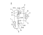
図25示すように、本形態の2次側冷媒回路(B)におけるガス流路切換え手段(8)は、上述した第5実施形態の冷媒回路において、ガス配管(6)に第2電磁弁(EV2)が設けられ、各分岐ガス流通管(4a,4b)とガス配管(6)との間にガス接続管(20)が設けられている。詳しくは、このガス接続管(20)は、一端が、ガス配管(6)における第2電磁弁(EV2)と室内熱交換器(3)との間に接続され、他端側が分岐されて第1及び第2の分岐ガス接続管(20a,20b)に構成されており、第1分岐ガス接続管(20a)が第1分岐ガス流通管(4a)に、第2分岐ガス接続管(20b)が第2分岐ガス流通管(4b)に夫々接続されている。また、ガス接続管(20)には第3電磁弁(EV3)が、各分岐ガス接続管(20a,20b)には室内熱交換器(3)から冷熱源熱交換器(2a,2b)へのガス冷媒の流通のみを許容するガス冷媒用逆止弁(CVG1,CVG2)が設けられている。
【0206】
一方、液流路切換え手段(9)は、上述した第6実施形態の冷媒回路において、第3逆止弁(CV3-1,CV3-2)に代えて請求項34記載の発明でいう第2の開閉弁としての第6電動弁(EV6-1,EV6-2)が各分岐液配管(7e,7f)に夫々設けられている。
【0207】
このような構成により、本2次側冷媒回路(B)における室内の暖房運転時にあっては、上述した第5実施形態で述べた暖房運転動作と同様の動作が行われて室内が連続的に暖房される。つまり、図26に示すように、一方の冷熱源熱交換器(2a)に対して液冷媒の回収動作が行われている場合には、他方の冷熱源熱交換器(2b)に対しては室内熱交換器(3)で凝縮された液冷媒が供給されており、この動作が交互に繰り返されることになる。
【0208】
逆に、室内の冷房運転時にあっては、上述した第6実施形態で述べた冷房運転動作と同様の動作が行われて室内が連続的に冷房される。つまり、図27に示すように、一方の冷熱源熱交換器(2a)から液冷媒が室内熱交換器(3)に供給されている場合には、他方の冷熱源熱交換器(2b)に対しては室内熱交換器(3)で蒸発されたガス冷媒が供給されており、この動作が交互に繰り返されることになる。また、この冷房運転動作に伴って温熱源熱交換器(1)の液冷媒の貯留量が所定量以下に達した場合には液流通管(5)から温熱源熱交換器(1)に液冷媒が回収される。
【0209】
(第8実施形態)
次に、請求項35〜40記載の発明に係る熱搬送装置の実施形態について図面に基いて説明する。本実施形態は、第1及び第2の2台の冷熱源熱交換器及び4つの室内の個々に配置された4台の室内熱交換器を備え、夫々が個別に冷房運転と暖房運転とを選択可能とされた所謂冷暖フリーのマルチ型空気調和装置として2次側冷媒回路を構成したものである。また、本形態では、回路構成として上述した第4実施形態との差異についてのみ説明する。
【0210】
図28に示すように、本形態の2次側冷媒回路(B)のガス流路切換え手段(8)としては、ガス流通管(4)の冷熱源熱交換器側が分岐されて第1及び第2の分岐ガス流通管(4a,4b)に形成されており、第1分岐ガス流通管(4a)が第1冷熱源熱交換器(2a)に、第2分岐ガス流通管(4b)が第2冷熱源熱交換器(2b)に夫々接続されている。また、この各分岐ガス流通管(4a,4b)には第1電磁弁(EV1-1,EV1-2)が夫々設けられている。
【0211】
また、一端が、ガス配管(6)における第2電磁弁(EV2-1〜EV2-4)と室内熱交換器(3a〜3d)との間に接続され、他端側が第1及び第2の分岐ガス接続管(20a,20b)に分岐されて、第1分岐ガス接続管(20a)が第1分岐ガス流通管(4a)に、第2分岐ガス接続管(20b)が第2分岐ガス流通管(4b)に夫々接続されたガス接続管(20)が設けられており、各分岐ガス接続管(20a,20b)にはガス冷媒用逆止弁(CVG1,CVG2)が設けられている。
【0212】
一方、液流路切換え手段(9)としては、液流通管(5)の冷熱源熱交換器側が分岐されて第1及び第2の分岐液流通管(5a,5b)に形成されており、第1分岐液流通管(5a)が第1冷熱源熱交換器(2a)に、第2分岐液流通管(5b)が第2冷熱源熱交換器(2b)に夫々接続されている。更に、液配管(7)における液流通管(5)との接続側も分岐されて第1及び第2の分岐液配管(7e,7f)に構成されており、第1分岐液配管(7e)が第1分岐液流通管(5a)に、第2分岐液配管(7f)が第2分岐液流通管(5b)に夫々接続されている。
【0213】
そして、この分岐液流通管(5a,5b)に対する分岐液配管(7e,7f)の接続位置と温熱源熱交換器(1)との間には冷熱源熱交換器(2a,2b)から温熱源熱交換器(1)への液冷媒の流通のみを許容する第1逆止弁(CV1-1,CV1-2)が夫々設けられ、上記各分岐液配管(7e,7f)には請求項40記載の発明でいう第3の開閉弁としての第6電動弁(EV6-1,EV6-2)が夫々設けられている。これら説明した構成以外の部分は上述した第4実施形態(図12参照)と同様の構成となっている。
【0214】
このような構成により、本2次側冷媒回路(B)における室内の空調運転時にあっては、上述した第4実施形態で述べた各室内熱交換器(3a〜3d)の運転状態に応じて冷媒の流通が切換えられ、また、各冷熱源熱交換器(2a,2b)での液冷媒の回収及び供給動作が交互に切換えられることにより、各室内熱交換器(3a〜3d)の運転が連続して行えることになる。
【0215】
つまり、各室全体の熱の収支が暖房要求である場合には、図29に示すように、一方の冷熱源熱交換器(2a)に対して温熱源熱交換器(1)への液冷媒の回収動作が行われている場合には、他方の冷熱源熱交換器(2b)では放熱運転する室内熱交換器(3a〜3c)から液冷媒が供給されると共に吸熱運転する室内熱交換器(3d)からガス冷媒が供給されており、この動作が交互に繰り返されることになる。
【0216】
また、各室全体の熱の収支が冷房要求である場合には、図30に示すように、一方の冷熱源熱交換器(2b)に対して吸熱運転する室内熱交換器(3b〜3d)からガス冷媒が供給されている場合には、他方の冷熱源熱交換器(2a)では温熱源熱交換器(1)への液冷媒の回収動作と吸熱運転する室内熱交換器(3b〜3d)への液冷媒の供給が行われており、この動作が交互に繰り返されることになる。
【0217】
更に、各室内熱交換器における放熱量と吸熱量とが同一である場合には、図31に示すように、一方の冷熱源熱交換器(2a)に対して温熱源熱交換器(1)への液冷媒の回収動作が行われている場合には、他方の冷熱源熱交換器(2b)では、放熱運転する室内熱交換器(3a,3b)から吸熱運転する室内熱交換器(3c,3d)へ供給されて該室内熱交換器(3c,3d)で蒸発したガス冷媒が供給されており、この動作が交互に繰り返されることになる。
【0218】
尚、全ての室内熱交換器(3a〜3d)が共に放熱運転を行う場合や吸熱運転を行う場合の動作は上述した第7実施形態の各動作と同様であるのでここでは省略する。
−複数の受液器を備えた変形例−
以下に述べる第9〜第12実施形態は、連続した空調運転を可能とするための変形例として、液冷媒の貯留が可能とされた複数台(本形態では2台)の受液器を備えさせたものである。
【0219】
(第9実施形態)
本形態は、第1及び第2の2台の受液器を備えたものであって、暖房専用の空気調和装置として2次側冷媒回路を構成したものである。図32に示すように、ガス流通管(4)は一部が分岐されて第1及び第2の分岐ガス流通管(4a,4b)に形成されており、第1分岐ガス流通管(4a)には第1ガス管(26a)を介して第1受液器(25a)が、第2分岐ガス流通管(4a)には第2ガス管(26b)を介して第2受液器(25b)が夫々接続されている。そして、各ガス流通管(4a,4b)におけるガス管(26a,26b)の接続位置と温熱源熱交換器(1)との間には請求項43記載の発明でいう第1の開閉弁としての第7電磁弁(EV7-1,EV7-2)が、各分岐ガス流通管(4a,4b)におけるガス管(26a,26b)の接続位置と冷熱源熱交換器(2)との間には請求項43記載の発明でいう第2の開閉弁としての第8電磁弁(EV8-1,EV8-2)が夫々設けられている。
【0220】
また、液流通管(5)も一部が分岐されて第1及び第2の分岐液流通管(5a,5b)に形成されており、第1分岐液流通管(5a)が第1液管(27a)を介して第1受液器(25a)に、第2分岐液流通管(5b)が第2液管(27b)を介して第2受液器(25b)に夫々接続されている。そして、この分岐液流通管(5a,5b)に対する液管(27a,27b)の接続位置と温熱源熱交換器(1)との間には受液器(25a,25b)から温熱源熱交換器(1)への液冷媒の流通のみを許容する第1逆止弁(CV1-1,CV1-2)が夫々設けられ、分岐液流通管(5a,5b)に対する液管(27a,27b)の接続位置と冷熱源熱交換器(2)との間には室内熱交換器(3)及び冷熱源熱交換器(2)から受液器(25a,25b)への液冷媒の流通のみを許容する第2逆止弁(CV2-1,CV2-2)が夫々設けられ、更に、液配管(7)には室内熱交換器(3)から受液器(25a,25b)への液冷媒の流通のみを許容する第4逆止弁(CV4)が設けられている。
【0221】
次に、上述の如く構成された本2次側冷媒回路(B)における室内の暖房運転時について説明する。この暖房運転時には、先ず、コントローラ(C)によって第1分岐ガス流通管(4a)の第7電磁弁(EV7-1)及び第2分岐ガス流通管(4b)の第8電磁弁(EV8-2)が開放される一方、第2分岐ガス流通管(4b)の第7電磁弁(EV7-2)及び第1分岐ガス流通管(4a)の第8電磁弁(EV8-1)が閉鎖される。この状態で、温熱源熱交換器(1)が1次側冷媒回路からの熱量を受け、温熱源熱交換器(1)では冷媒が蒸発して、該温熱源熱交換器(1)から高圧のガス冷媒は、図33(a)に示すように、その一部が第1分岐ガス流通管(4a)及び第1ガス管(26a)を経て第1受液器(25a)に、他がガス配管(6)を経て室内熱交換器(3)に供給される。そして、この室内熱交換器(3)においてガス冷媒が室内空気との間で熱交換して凝縮され室内空気を加温して室内を暖房する。そして、この状態では、室内熱交換器(3)と第2受液器(25b)との圧力差によって、図33(b)に示すように、室内熱交換器(3)の液冷媒は第2分岐液流通管(5b)を経て第2受液器(25b)に供給されることになる。つまり、この暖房運転に伴って第2受液器(25b)には液冷媒が貯留されていくことになる。一方、第1受液器(25a)にあっては温熱源熱交換器(1)からガス冷媒が供給されていることにより、この第1受液器(25a)の液冷媒は第1液管(27a)及び第1分岐液流通管(5a)から温熱源熱交換器(1)に回収されている。
【0222】
そして、このような暖房運転が所定時間行われて、上記第2受液器(25b)における液冷媒の貯留量が所定量以上に達した時には、コントローラ(C)によって第2分岐ガス流通管(4b)の第7電磁弁(EV7-2)及び第1分岐ガス流通管(4a)の第8電磁弁(EV8-1)が開放される一方、第1分岐ガス流通管(4a)の第7電磁弁(EV7-1)及び第2分岐ガス流通管(4b)の第8電磁弁(EV8-2)が閉鎖される。これにより、温熱源熱交換器(1)から高圧のガス冷媒は、図33(c)に示すように、その一部が第2分岐ガス流通管(4b)を経て第2受液器(25b)に、他がガス配管(6)を経て室内熱交換器(3)に供給される。そして、この室内熱交換器(3)においてガス冷媒が室内空気との間で熱交換して凝縮され室内空気を加温して室内を暖房する。そして、この状態では、ガス配管(6)と液配管(7)との圧力差によって、図33(d)に示すように、室内熱交換器(3)の液冷媒は第1分岐液流通管(5a)を経て第1受液器(25a)に供給されることになる。つまり、この暖房運転に伴って第1受液器(25a)には液冷媒が貯留されていくことになる。一方、第2受液器(25b)にあっては温熱源熱交換器(1)からガス冷媒が供給されていることにより、この第2受液器(25b)の液冷媒は第2分岐液流通管(5b)から温熱源熱交換器(1)に回収される。このような動作が交互に行われる。
【0223】
このように、本形態の構成によれば、2台の受液器(25a,25b)を設けて、一方において室内熱交換器(3)との間で冷媒を流通させながら、他方で液冷媒を温熱源熱交換器(1)に回収させ、この各受液器(25a,25b)の動作を交互に行わせるようにしたことで、室内熱交換器(3)における放熱運転を連続して行うことができる。つまり、室内の暖房運転を連続して行うことができるので、室内の快適性の向上を図ることができる。
【0224】
(第10実施形態)
本形態は、請求項45〜48記載の発明に係る実施形態として第1及び第2の2台の受液器を備えたものであって、冷房専用の空気調和装置として2次側冷媒回路を構成したものである。尚、本形態では、上述した第9実施形態との相違点についてのみ説明する。
【0225】
図34に示すように、ガス配管(6)のガス流通管(4)に対する接続位置は第2分岐ガス流通管(4b)における第8電磁弁(EV8-2)と冷熱源熱交換器(2)との間になっている。
【0226】
また、液配管(7)の液流通管(5)に対する接続位置は第2分岐液流通管(5b)における第1逆止弁(CV1-2)と温熱源熱交換器(1)との間になっている。更に、液流通管(5)には第4電磁弁(EV4)が設けられている。また、本形態の液配管(7)には、第4逆止弁(CV4)が設けられていない。その他の構成は上述した第9実施形態と同様の構成となっている。
【0227】
次に、上述の如く構成された本冷媒回路(B)における室内の冷房運転時について説明する。この冷房運転開始時には、先ず、コントローラ(C)によって、第1分岐ガス流通管(4a)に設けられた第7電磁弁(EV7-1)及び第2分岐ガス流通管(4b)に設けられた第8電磁弁(EV8-2)が開放され、且つ第2分岐ガス流通管(4b)に設けられた第7電磁弁(EV7-2)及び第1分岐ガス流通管(4a)に設けられた第8電磁弁(EV8-1)が閉鎖される。この状態で、図35(a)に示すように、温熱源熱交換器(1)からの高圧のガス冷媒が第1分岐ガス流通管(4a)を介して第1受液器(25a)に供給される。すると、この圧力の作用により、予め第1受液器(25a)に貯留されていた液冷媒は、第1分岐液流通管(5a)及び液配管(7)を介して室内熱交換器(3)に導入される。そして、室内熱交換器(3)において液冷媒が室内空気との間で熱交換して蒸発され室内空気を冷却して室内が冷房される。そして、この際、冷媒が凝縮する冷熱源熱交換器(2)と冷媒が蒸発する室内熱交換器(3)との圧力差によって、図35(b)に示すように、室内熱交換器(3)のガス冷媒はガス配管(6)を経て冷熱源熱交換器(2)に供給され、更にその後、ガス冷媒は冷熱源熱交換器(2)で凝縮し、液冷媒となって第2分岐液流通管(5b)を経て第2受液器(25b)に供給されることになる。
【0228】
そして、このような状態が所定時間継続して行われ、第1受液器(25a)の液冷媒の貯留量が所定量以下になると、コントローラ(C)によって、第2分岐ガス流通管(4b)に設けられた第7電磁弁(EV7-2)及び第1分岐ガス流通管(4a)に設けられた第8電磁弁(EV8-1)が開放され、且つ第1分岐ガス流通管(4a)に設けられた第7電磁弁(EV7-1)及び第2分岐ガス流通管(4b)に設けられた第8電磁弁(EV8-2)が閉鎖される。これにより、図35(c)に示すように、温熱源熱交換器(1)からの高圧のガス冷媒が第2分岐ガス流通管(4b)を介して第2受液器(25b)に供給される。すると、この圧力の作用により、第2受液器(25b)に貯留されている液冷媒は、第2分岐液流通管(5b)及び液配管(7)を介して室内熱交換器(3)に導入される。そして、室内熱交換器(3)において液冷媒が室内空気との間で熱交換して蒸発され室内空気を冷却して室内が冷房される。そして、この際、冷熱源熱交換器(2)と室内熱交換器(3)との圧力差によって、図35(d)に示すように、室内熱交換器(3)のガス冷媒はガス配管(6)を経て冷熱源熱交換器(2)に供給され、更にその後、ガス冷媒は冷熱源熱交換器(2)で凝縮し、液冷媒となって第1分岐液流通管(5a)を経て第1受液器(25a)に供給されることになる。
【0229】
このような各受液器(25a,25b)の動作を交互に行わせることにより、室内熱交換器(3)における吸熱運転を連続して行うことができる。つまり、室内の冷房運転を連続して行うことができる。
【0230】
そして、このような冷房運転が所定時間行われて、温熱源熱交換器(1)の液冷媒の貯留量が所定量以下に達した時には、コントローラ(C)により、液冷媒が貯留されている受液器(25a),(25b)に繋る第7電磁弁(EV7-1),(EV7-2)及び第4電磁弁(EV4)が共に開放され、温熱源熱交換器(1)と冷熱源熱交換器(2)とが均圧され、冷熱源熱交換器(2)の液冷媒が温熱源熱交換器(1)に回収される。
【0231】
(第11実施形態)
次に、請求項49〜52記載の発明に係る係る熱搬送装置の実施形態について図面に基いて説明する。本形態は、第1及び第2の2台の受液器を備えたものであって、暖房運転と冷房運転とが切換え可能な空気調和装置として2次側冷媒回路を構成したものである。尚、本形態でも、上述した各実施形態との相違点についてのみ説明する。
【0232】
図36示すように、本形態の2次側冷媒回路(B)におけるガス流路切換え手段(8)は、上述した第9実施形態の冷媒回路において、ガス配管(6)に請求項51記載の発明でいう第3の開閉弁としての第2電磁弁(EV2)が設けられ、各分岐ガス流通管(4a,4b)とガス配管(6)との間にガス接続管(20)が設けられている。詳しくは、このガス接続管(20)は、一端が、ガス配管(6)における第2電磁弁(EV2)と室内熱交換器(3)との間に接続され、他端側が第2分岐ガス流通管(4b)における第8電磁弁(EV8-2)と冷熱源熱交換器(2)との間に接続されている。また、ガス接続管(20)には請求項51記載の発明でいう第4の開閉弁としての第3電磁弁(EV3)が設けられている。
【0233】
一方、液流路切換え手段(9)は、上述した第10実施形態の冷媒回路に加えて、液配管(7)に第9電磁弁(EV9)が設けられ、各分岐液流通管(5a,5b)と液配管(7)との間に液接続管(21)が設けられている。詳しくは、この液接続管(21)は、一端が、液配管(7)における第9電磁弁(EV9)と室内熱交換器(3)との間に接続され、他端側が第2分岐液流通管(5b)における第2逆止弁(CV2-2)と冷熱源熱交換器(2)との間に接続されている。また、液接続管(21)には第10電磁弁(EV10)が設けられている。
【0234】
このような構成により、本2次側冷媒回路(B)における室内の暖房運転時にあっては、上述した第9実施形態で述べた暖房運転動作と同様の動作が行われて室内が連続的に暖房される。つまり、図37に示すように、一方の受液器(25a)に対して液冷媒の回収動作が行われている場合には、他方の受液器(25b)に対しては室内熱交換器(3)で凝縮された液冷媒が供給されており、この動作が交互に繰り返されることになる。
【0235】
逆に、室内の冷房運転時にあっては、上述した第10実施形態で述べた冷房運転動作と同様の動作が行われて室内が連続的に冷房される。つまり、図38に示すように、一方の受液器(25a)から液冷媒が室内熱交換器(3)に供給されている場合には、他方の受液器(25b)に対しては、室内熱交換器(3)で蒸発された後、冷熱源熱交換器(2)で凝縮された液冷媒が供給されており、この動作が交互に繰り返されることになる。また、この冷房運転動作に伴って温熱源熱交換器(1)の液冷媒の貯留量が所定量以下に達した場合には液流通管(5)から温熱源熱交換器(1)に液冷媒が回収される。
【0236】
(第12実施形態)
次に、請求項53〜58記載の発明に係る熱搬送装置の実施形態について図面に基いて説明する。本形態は、第1及び第2の2台の受液器及び4つの室内の個々に配置された4台の室内熱交換器を備え、夫々が個別に冷房運転と暖房運転とを選択可能とされた所謂冷暖フリーのマルチ型空気調和装置として2次側冷媒回路を構成したものである。また、本形態では、回路構成として上述した第4実施形態との差異についてのみ説明する。
【0237】
図39に示すように、本形態の2次側冷媒回路(B)のガス流路切換え手段(8)としては、ガス流通管(4)の一部が分岐されて第1及び第2の分岐ガス流通管(4a,4b)に形成されており、第1分岐ガス流通管(4a)が第1ガス管(26a)を介して第1受液器(25a)に、第2分岐ガス流通管(4b)が第2ガス管(26b)を介して第2受液器(25b)に夫々接続されている。また、各ガス流通管(4a,4b)におけるガス管(26a,26b)の接続位置と温熱源熱交換器(1)との間には第7電磁弁(EV7-1,EV7-2)が、各分岐ガス流通管(4a,4b)におけるガス管(26a,26b)の接続位置と冷熱源熱交換器(2)との間には第8電磁弁(EV8-1,EV8-2)が夫々設けられている。
【0238】
また、液流通管(5)も一部が分岐されて第1及び第2の分岐液流通管(5a,5b)に形成されており、第1分岐液流通管(5a)が第1液管(27a)を介して第1受液器(25a)に、第2分岐液流通管(5b)が第2液管(27b)を介して第2受液器(25b)に夫々接続されている。
【0239】
そして、この分岐液流通管(5a,5b)に対する液管(27a,27b)の接続位置と温熱源熱交換器(1)との間には受液器(25a,25b)から温熱源熱交換器(1)への液冷媒の流通のみを許容する第1逆止弁(CV1-1,CV1-2)が夫々設けられ、分岐液流通管(5a,5b)に対する液管(27a,27b)の接続位置と冷熱源熱交換器(2)との間には室内熱交換器(3a〜3d)及び冷熱源熱交換器(2)から受液器(25a,25b)への液冷媒の流通のみを許容する第2逆止弁(CV2-1,CV2-2)が夫々設けられ、更に、液配管(7)には第9電磁弁(EV9)が設けられ、各分岐液流通管(5a,5b)と液配管(7)との間に液接続管(21)が設けられている。詳しくは、この液接続管(21)は、一端が、液配管(7)における第9電磁弁(EV9)と室内熱交換器(3a〜3d)との間に接続され、他端側が第2分岐液流通管(5b)における第2逆止弁(CV2-2)と冷熱源熱交換器(2)との間に接続されている。また、液接続管(21)には第10電磁弁(EV10)が設けられている。これら説明した構成以外の部分は上述した第4実施形態(図12参照)と同様の構成となっている。
【0240】
このような構成により、本2次側冷媒回路(B)における室内の空調運転時にあっては、上述した第4実施形態で述べた各室内熱交換器(3a〜3d)の運転状態に応じて冷媒の流通が切換えられ、また、各受液器(25a,25b)での液冷媒の回収及び供給動作が交互に切換えられることにより、各室内熱交換器(3a〜3d)の運転が連続して行えることになる。
【0241】
つまり、各室全体の熱の収支が暖房要求である場合には、図40に示すように、一方の受液器(25a)に対して温熱源熱交換器(1)への液冷媒の回収動作が行われている場合には、他方の受液器(25b)では放熱運転する室内熱交換器(3a〜3c)から液冷媒が供給されており、この動作が交互に繰り返されることになる。
【0242】
また、各室全体の熱の収支が冷房要求である場合には、図41に示すように、一方の受液器(25b)に対して、吸熱運転する室内熱交換器(3b〜3d)で蒸発した後、冷熱源熱交換器(2)で凝縮された液冷媒が供給されている場合には、他方の受液器(25a)では温熱源熱交換器(1)への液冷媒の回収動作と吸熱運転する室内熱交換器(3a)への液冷媒の供給が行われており、この動作が交互に繰り返されることになる。
【0243】
更に、各室内熱交換器(3a〜3d)における放熱量と吸熱量とが同一である場合には、図42に示すように、一方の受液器(25a)に対して温熱源熱交換器(1)への液冷媒の回収動作が行われている場合には、他方の受液器(25b)では、放熱運転する室内熱交換器(3a,3b)から吸熱運転する室内熱交換器(3c,3d)へ供給されて該室内熱交換器(3c,3d)で蒸発したガス冷媒が供給されており、この動作が交互に繰り返されることになる。
【0244】
尚、全ての室内熱交換器(3a〜3d)が共に放熱運転を行う場合や吸熱運転を行う場合の動作は上述した第11実施形態の各動作と同様であるのでここでは省略する。
−1次側冷媒回路の変形例−
以上、2次側冷媒回路(B)について説明したが、以下に、これらの2次側冷媒回路(B)と組合せ可能な1次側冷媒回路(A)についての複数の変形例について説明する。尚、以下に説明する1次側冷媒回路(A)の変形例では、2次側冷媒回路(B)についての説明を省略する。また、以下の回路において同様の機能を有する部材については同一名称及び同一符号を付す。
【0245】
(第13実施形態)
本形態は、第1実施形態の暖房専用の空気調和装置に対して適用される1次側冷媒回路(A)の変形例である。この回路(A)は、図43に示すように、圧縮機(11)、温熱源熱交換器(1)との間で熱交換が可能とされた加熱用熱交換器(12)、膨張機構としての第1電動弁(18a)及び冷熱源熱交換器(2)との間で熱交換が可能とされた冷却用熱交換器(15)が冷媒配管(16)により冷媒の循環が可能に順に接続されてメイン冷媒循環路(30)が構成されている。
【0246】
そして、上記電動弁(18a)及び加熱用熱交換器(12)の間と、圧縮機(11)及び冷却用熱交換器(15)の間とを接続するバイパス路(17)が備えられ、該バイパス路(17)には、熱量調整熱交換器(14)及び該熱量調整熱交換器(14)を流れる冷媒の流量を調整するように開度が変更される調整弁としての第2電動弁(18b)が設けられている。また、各電動弁(18a,18b)は図示しないコントローラによって開度が調整される。
【0247】
このような構成により、この1次側冷媒回路(A)での冷媒循環時には、加熱用熱交換器(12)から温熱源熱交換器(1)に与えられる熱量と、冷却用熱交換器(15)により冷熱源熱交換器(2)から奪われる熱量との差に応じて各電動弁(18a,18b)が開度調整され、圧縮機(11)から吐出された冷媒は、加熱用熱交換器(12)において温熱源熱交換器(1)との間で熱交換を行って凝縮し、この加熱用熱交換器(12)から導出された液冷媒は、各電動弁(18a,18b)の各開度に応じて、その一部がメイン循環路(第1電動弁(18a)側)に、他がバイパス路(第2電動弁(18b)側)に導かれる。そして、メイン循環路(30)に導かれた液冷媒は第1電動弁(18a)で減圧された後、冷却用熱交換器(15)において冷熱源熱交換器(2)との間で熱交換を行って蒸発する一方、バイパス路(17)に導かれた液冷媒は第2電動弁(18b)で減圧された後、熱量調整熱交換器(14)において例えば外気との間で熱交換を行って蒸発し、これら蒸発したガス冷媒が圧縮機(11)に吸入されるといった循環動作を繰り返す。
【0248】
このような冷媒の循環動作であるために、熱量調整熱交換器(14)における吸熱量を、上記の熱交換量の差分と等しくなるように、流量調整電動弁(18)の開度を設定すれば、1次側冷媒回路(A)全体としての放熱量と吸熱量とを等しくできて、該1次側冷媒回路(A)での冷媒の循環を良好に行わせることができる。
【0249】
(第14実施形態)
本形態は、請求項63、64記載の発明に係る実施形態であって、冷房専用の空気調和装置に対して適用される1次側冷媒回路(A)である。また、本形態では、上述した第1実施形態で説明した1次側冷媒回路との相違点についてのみ説明する。
【0250】
図44に示すように、本形態の1次側冷媒回路(A)は、膨張弁(13)が熱量調整用熱交換器(14)と冷却用熱交換器(15)との間に設けられており、バイパス路(17)は、一端が膨張弁(13)と熱量調整用熱交換器(14)との間に、他端が加熱用熱交換器(12)と熱量調整用熱交換器(14)との間に夫々接続されている。つまり、熱量調整用熱交換器(14)においてガス冷媒が例えば外気との間で熱交換を行って凝縮するような構成とされている。
【0251】
このような構成により、熱量調整熱交換器(14)における放熱量が、加熱用熱交換器(12)から温熱源熱交換器(1)に与えられる熱量と、冷却用熱交換器(15)により冷熱源熱交換器(2)から奪われる熱量との差と等しくなるように、流量調整電動弁(18)の開度を設定すれば、1次側冷媒回路(A)全体としての放熱量と吸熱量とを等しくできて、該1次側冷媒回路(A)での冷媒の循環を良好に行わせることができる。
【0252】
(第15実施形態)
本形態は、請求項65、66記載の発明に係る実施形態であって、冷房専用の空気調和装置に対して適用される1次側冷媒回路(A)の変形例である。また、本形態では、上述した第13実施形態で説明した1次側冷媒回路との相違点についてのみ説明する。
【0253】
図45に示すように、本形態の1次側冷媒回路(A)は、バイパス路(17)の一端が膨張機構としての第1電動弁(18a)と冷却用熱交換器(15)との間に接続されている一方、他端が圧縮機(11)の吐出側、つまり、圧縮機(11)と加熱用熱交換器(12)との間に接続されている。つまり、圧縮機(11)から吐出されたガス冷媒が加熱用熱交換器(12)及び熱量調整熱交換器(14)に分岐供給される構成となっている。
【0254】
このような構成により、熱量調整熱交換器(14)における放熱量が、加熱用熱交換器(12)から温熱源熱交換器(1)に与えられる熱量と、冷却用熱交換器(15)により冷熱源熱交換器(2)から奪われる熱量との差と等しくなるように、各電動弁(18a,18b)の開度を設定すれば、1次側冷媒回路(A)全体としての放熱量と吸熱量とを等しくできて、該1次側冷媒回路(A)での冷媒の循環を良好に行わせることができる。
【0255】
(第16実施形態)
本形態は、請求項67、68記載の発明に係る実施形態であって、冷暖房の切換え運転が可能とされた空気調和装置に対して適用される1次側冷媒回路(A)の変形例である。また、本形態では、上述した第1実施形態で説明した1次側冷媒回路との相違点についてのみ説明する。
【0256】
図46に示すように、本形態の1次側冷媒回路(A)は、加熱用熱交換器(12)から導出された液冷媒を、膨張弁(13)を経て熱量調整熱交換器(14)及びバイパス路(17)へ導く第1の切換え状態と、熱量調整熱交換器(14)及びバイパス路(17)を経て膨張弁(13)へ導く第2の切換え状態とに切換え可能とされた四路切換弁(19)が備えられている。その他の構成は上述した第1実施形態と同様である。
【0257】
このような構成であるために、室内の暖房運転時(室内熱交換器(3)の放熱時)には、四路切換弁(19)が図46に破線で示す第1の切換え状態とされ、熱量調整熱交換器(14)において冷媒が吸熱して蒸発されることになると共に、この吸熱量は流量調整用電動弁(18)によって調整されることになる。一方、室内の冷房運転時(室内熱交換器(3)の吸熱時)には、四路切換弁(19)が図46に実線で示す第2の切換え状態とされ、熱量調整熱交換器(14)において冷媒が放熱して凝縮されることになると共に、この放熱量は流量調整用電動弁(18)によって調整されることになる。このような動作により、冷暖何れの運転状態であっても、1次側冷媒回路(A)全体としての放熱量と吸熱量とを等しくできて、該1次側冷媒回路(A)での冷媒の循環を良好に行わせることができる。
【0258】
また、この第16実施形態の変形例として、図47に示すものは、室内の暖房運転時に、熱量調整熱交換器(14)に着霜が発生した場合に、この霜を融解するための除霜手段としてのデフロスト回路(31)を備えたものである。具体的には、一端が圧縮機(11)と加熱用熱交換器(12)との間(圧縮機(11)の吐出側)に、他端が熱量調整熱交換器(14)と四路切換弁(19)との間に夫々接続されたホットガス管(32)が備えられ、このホットガス管(32)における両端部近傍位置にはデフロスト用第1電磁弁(EVD1,EVD1)が夫々設けられている。また、一端が加熱用熱交換器(12)とホットガス管(32)の一端部との間に、他端が冷却用熱交換器(15)と圧縮機(11)との間(圧縮機(11)の吐出側)に夫々接続された冷媒回収管(33)が備えられ、この冷媒回収管(33)にはデフロスト用第2電磁弁(EVD2)が設けられている。また、冷媒配管(16)における圧縮機(11)の吐出側でのホットガス管(32)の接続位置と冷媒回収管(33)の接続位置との間及び冷媒配管(16)における圧縮機(11)の吸入側での冷媒回収管(33)の接続位置と冷却用熱交換器(15)との間にはデフロスト用第3電磁弁(EVD3,EVD3)が夫々備えられている。
【0259】
このような構成により、熱量調整熱交換器(14)に着霜が発生した場合には、四路切換弁(19)が図47の破線側に切換えられ、デフロスト用第3電磁弁(EVD3,EVD3)が閉鎖されると共に、デフロスト用第1電磁弁(EVD1,EVD1)及びデフロスト用第2電磁弁(EVD2)が開放されて、圧縮機(11)からの高温の吐出冷媒は、ホットガス管(32)を経て熱量調整熱交換器(14)に導入されて霜を融解し、その後、膨張弁(13)、四路切換弁(19)、加熱用熱交換器(12)及び冷媒回収管(33)を経て圧縮機(11)に回収されることになる。このため、熱量調整熱交換器(14)の着霜を迅速に解消することができ、室内の空調性能の向上を図ることができる。
【0260】
また、このようなデフロスト回路(31)は、本形態のような冷暖房の切換え運転が可能とされた空気調和装置に対してばかりでなく、上述した第1実施形態及び第13実施形態に対しても適用可能である。
【0261】
(第17実施形態)
本形態は、請求項69、70記載の発明に係る実施形態であって、冷暖房の切換え運転が可能とされた空気調和装置に対して適用される1次側冷媒回路(A)の変形例である。また、本形態では、上述した第13実施形態(図43参照)で説明した1次側冷媒回路との相違点についてのみ説明する。
【0262】
図48に示すように、本形態の1次側冷媒回路(A)は、加熱用熱交換器(12)の出口側に第3電動弁(18c)を備えていると共に、圧縮機(11)と熱量調整熱交換器(14)との間のバイパス管(17)は、吸入側分岐管(17a)と吐出側分岐管(17b)とに分岐されて、吸入側分岐管(17a)が圧縮機(11)の吸入側に、吐出側分岐管(17b)が圧縮機(11)の吐出側に夫々接続されている。また、吸入側分岐管(17a)には、室内の暖房時に開放され、冷房時に閉鎖される吸入側電磁弁(EVI)が、吐出側分岐管(17b)には、室内の暖房時に閉鎖され、冷房時に開放される吐出側電磁弁(EVO)が夫々設けられている。その他の構成は上述した第13実施形態と同様である。
【0263】
このような構成であるために、室内の暖房運転時(室内熱交換器(3)の放熱時)には、吸入側電磁弁(EVI)が開放されると共に吐出側電磁弁(EVO)が閉鎖され、熱量調整熱交換器(14)において冷媒が吸熱して蒸発されることになると共に、この吸熱量は各電動弁(18a,18b)によって調整されることになる。一方、室内の冷房運転時(室内熱交換器(3)の吸熱時)には、吸入側電磁弁(EVI)が閉鎖されると共に吐出側電磁弁(EVO)が開放され、熱量調整熱交換器(14)において冷媒が放熱して凝縮されることになると共に、この放熱量は流量調整用電動弁(18a,18b)によって調整されることになる。このような動作により、冷暖何れの運転状態であっても、1次側冷媒回路(A)全体としての放熱量と吸熱量とを等しくできて、該1次側冷媒回路(A)での冷媒の循環を良好に行わせることができる。
【0264】
また、この第17実施形態の変形例として、図49に示すものは、室内の暖房運転時に、熱量調整熱交換器(14)に着霜が発生した場合に、この霜を融解するためのデフロスト回路(31)を備えたものである。具体的には、一端が圧縮機(11)と加熱用熱交換器(12)との間(圧縮機(11)の吐出側)に、他端が圧縮機(11)と冷却用熱交換器(15)との間(圧縮機(11)の吸入側)に夫々接続された冷媒回収管(33)が備えられ、この冷媒回収管(33)にデフロスト用第3電磁弁(EVD3)が設けられている。また、冷媒配管(16)における圧縮機(11)の吐出側と冷媒回収管(33)の接続位置との間にはデフロスト用第4電磁弁(EVD4)が設けられている。
【0265】
このような構成により、熱量調整熱交換器(14)に着霜が発生した場合には、吸入側電磁弁(EVI)及びデフロスト用第4電磁弁(EVD4)が閉鎖され、吐出側電磁弁(EVO)及びデフロスト用第3電磁弁(EVD3)が開放されて、圧縮機(11)からの高温の吐出冷媒は、吐出側分岐管(17b)を経て熱量調整熱交換器(14)に導入されて霜を融解し、その後、第2及び第3膨張弁(18b,18c)、加熱用熱交換器(12)及び冷媒回収管(33)を経て圧縮機(11)に回収されることになる。このため、熱量調整熱交換器(14)の着霜を迅速に解消することができ、室内の空調性能の向上を図ることができる。
【0266】
また、このようなデフロスト回路(31)は、本形態のような冷暖房の切換え運転が可能とされた空気調和装置に対してばかりでなく、上述した第13実施形態の回路に対しても適用可能である。
【0267】
尚、上述した各1次側冷媒回路(A)の構成は、複数の受液器(25a,25b)を備えさせた第9〜第12実施形態に対しても適用可能である。
−複数の冷熱源熱交換器を備えた変形例−
以下に述べる第18〜第23実施形態は、2次側冷媒回路に冷熱源熱交換器を複数台(本形態では2台)備えさせた場合における1次側冷媒回路の構成を示している。
【0268】
(第18実施形態)
本形態は、図50に示すように、上述した第1実施形態において2次側冷媒回路(B)に2台の冷熱源熱交換器(2a,2b)を備えさせた場合であって、1次側冷媒回路(A)としては上述した第1実施形態(図1参照)と同様の構成を採用している。このような構成の場合、1次側冷媒回路(A)には、各冷熱源熱交換器(2a,2b)に対応して冷却用熱交換器(15a,15b)が備えられ、冷媒配管(16)が各冷却用熱交換器(15a,15b)に応じて分岐され、各分岐管(16a,16b)に、各冷却用熱交換器(15a,15b)への冷媒流量を調整するための電動弁(EVA,EVB)が備えられることになる。また、2次側冷媒回路(B)の構成は、上述した第5実施形態(図21参照)と同様である。
【0269】
(第19実施形態)
本形態は、図51に示すように、上述した第1実施形態において2次側冷媒回路(B)に2台の冷熱源熱交換器(2a,2b)を備えさせた場合であって、1次側冷媒回路(A)としては上述した第13実施形態(図43参照)と同様の構成を採用している。このような構成の場合、1次側冷媒回路(A)は、冷媒配管(16)の各分岐管(16a,16b)に、各冷却用熱交換器(15a,15b)への冷媒流量を調整するための第2電動弁(18a-1,18a-2)が備えられることになる。また、この場合にも2次側冷媒回路の構成は上述した第5実施形態(図21参照)と同様である。
【0270】
(第20実施形態)
本形態は、図52に示すように、上述した第14実施形態(図44参照)において2次側冷媒回路(B)に2台の冷熱源熱交換器(2a,2b)を備えさせた場合である。このような構成の場合、1次側冷媒回路(A)は、冷媒配管(16)の各分岐管(16a,16b)に、各冷却用熱交換器(15a,15b)への冷媒流量を調整するための電動弁で成る膨張弁(13a,13b)が備えられることになる。また、2次側冷媒回路(B)の構成は、上述した第6実施形態(図23参照)と同様である。
【0271】
(第21実施形態)
本形態は、図53に示すように、上述した第15実施形態(図45参照)において2次側冷媒回路(B)に2台の冷熱源熱交換器(2a,2b)を備えさせた場合である。このような構成の場合、1次側冷媒回路(A)は、冷媒配管(16)の各分岐管(16a,16b)に、各冷却用熱交換器(15a,15b)への冷媒流量を調整するための電動弁(18d-1,18d-2)が備えられることになる。また、この場合にも2次側冷媒回路(B)の構成は上述した第6実施形態(図23参照)と同様である。
【0272】
(第22実施形態)
本形態は、図54に示すように、上述した第16実施形態(図46参照)において2次側冷媒回路(B)に2台の冷熱源熱交換器(2a,2b)を備えさせた場合である。このような構成の場合、1次側冷媒回路(A)は、冷媒配管(16)の各分岐管(16a,16b)に、各冷却用熱交換器(15a,15b)への冷媒流量を調整するための電動弁で成る膨張弁(18d-1,18d-2)が備えられることになる。また、2次側冷媒回路(B)の構成は、上述した第7実施形態(図25参照)と同様である。
【0273】
(第23実施形態)
本形態は、図55に示すように、上述した第17実施形態(図48参照)において2次側冷媒回路(B)に2台の冷熱源熱交換器(2a,2b)を備えさせた場合である。このような構成の場合、1次側冷媒回路(A)の各分岐管(16a,16b)に、各冷却用熱交換器(15a,15b)への冷媒流量を調整するための電動弁(18a-1,18a-2)が備えられることになる。また、この場合にも2次側冷媒回路(B)の構成は上述した第7実施形態(図25参照)と同様である。
【0274】
また、上述した各実施形態は、室内の空気調和を行うようにした空気調和機の冷媒回路に本発明を適用した場合について説明したが、本発明は、これに限らず、冷蔵庫用の冷媒回路など種々の冷凍機に対して適用可能である。
【0275】
更に、上述した各実施形態では、2次側冷媒回路(B)の温熱源熱交換器(1)は1次側冷媒回路(A)を循環する冷媒から熱が与えられ、2次側冷媒回路(B)の冷熱源熱交換器(2)は1次側冷媒回路(A)を循環する冷媒により熱が奪われるようになっていたが、請求項1〜58記載の発明はこれに限らず、2次側冷媒回路(B)の温熱源熱交換器(1)にヒータを取付けて、該ヒータからの熱により冷媒を蒸発させたり、冷熱源熱交換器(2)を外気との間で熱交換させるような構成としてもよい。
【0276】
尚、本発明では、1次側冷媒回路(A)圧縮機(11)に代えて吸収式冷凍機を備えさせるようにしてもよい。
【0277】
【発明の効果】
以上説明してきたように、本発明によれば以下に述べるような効果が発揮される。請求項1記載の発明によれば、利用側手段に所定の熱交換動作を行わせるための冷媒の循環動作を、温熱源手段に与えられた熱量によって発生する冷媒の圧力上昇を利用して行うようにしたので冷媒循環用のポンプ等の駆動源を必要としない。このため、消費電力の低減、故障発生要因箇所の削減、装置全体としての信頼性の確保を図ることができる。また、冷熱源手段において冷媒の凝縮を行っているのでガス冷媒を確実に液化することができ、この冷熱源手段の内圧の上昇が抑制でき、良好な冷媒の循環動作を行うことができる。このため、従来のように利用側手段からガス冷媒が流出しないように、該利用側手段において冷媒を過冷却状態にしておく必要がなくなり、利用側手段における熱交換量を十分に得ることができ能力の向上を図ることができ、また、機器の配設位置の制約が小さくできて高い信頼性及び汎用性を得ることができる。
【0278】
また、液冷媒を貯留可能な受液手段を冷熱源手段に対して並列に接続したことにより受液手段に液冷媒を貯留できるので、冷熱源手段に液冷媒が貯留されることによる熱交換面積の減少を回避することができ、この冷熱源手段の熱交換効率を高く維持でき、装置全体としての効率の向上を図ることができる。
【0279】
請求項23記載の発明によれば、複数の冷熱源手段を備えさせ、常に一部の冷熱源手段を利用側手段との間で冷媒を循環させながら各冷熱源手段同士で利用側手段に対する接続状態を切換えることができ、請求項41記載の発明によれば、液冷媒を貯留可能な複数の受液手段を備えさせ、常に一部の受液手段と利用側手段との間で冷媒を循環させながら各受液手段同士で利用側手段に対する接続状態を切換えることができるので、利用側手段において連続した放熱運転を行うことができ、装置の性能の向上を図ることができる。
【0280】
請求項2、24及び42記載の発明によれば、利用側手段が放熱運転するものに対して、上述した請求項1記載の発明と同様に、駆動源が不要であることによる消費電力の低減、故障発生要因箇所の削減、装置全体としての信頼性の確保、冷熱源手段において冷媒の凝縮を行うことによる良好な冷媒の循環動作といった効果を発揮させることができる。そして、特に、請求項24記載の発明では、複数の冷熱源手段を備えさせ、一方において利用側手段との間で冷媒を流通させながら、他方で液冷媒を温熱源手段に回収させ、この各冷熱源手段の動作を交互に行わせるようにしているので、利用側手段における放熱運転を連続して行うことができ、本装置を室内の暖房を行う空気調和機に適用した場合には暖房運転を連続して行うことができて、室内の快適性の向上を図ることができる。また、請求項42記載の発明では、複数の受液手段を備えさせ、一方において利用側手段との間で冷媒を流通させながら、他方で液冷媒を温熱源手段に回収させ、この各受液手段の動作を交互に行わせるようにしているので、この場合にも利用側手段における放熱運転を連続して行うことができる。
【0281】
請求項6、27及び45記載の発明によれば、利用側手段が吸熱運転するものに対して、上述した請求項1記載の発明に係る効果を発揮することができる。そして、特に、請求項27記載の発明では、複数の冷熱源手段を備えさせ、一方において利用側手段との間で冷媒を流通させながら、他方で液冷媒を温熱源手段に回収させ、この各冷熱源手段の動作を交互に行わせるようにしているので、利用側手段における吸熱運転を連続して行うことができ、本装置を室内の冷房を行う空気調和機に適用した場合には冷房運転を連続して行うことができて、室内の快適性の向上を図ることができる。また、請求項45記載の発明では、複数の受液手段を備えさせ、一方において利用側手段との間で冷媒を流通させながら、他方で液冷媒を温熱源手段に回収させ、この各受液手段の動作を交互に行わせるようにしているので、この場合にも利用側手段における吸熱運転を連続して行うことができる。
【0282】
請求項10、31及び49記載の発明によれば、利用側手段が放熱運転と吸熱運転とが可能なものに対して、上述した請求項1記載の発明に係る効果を発揮することができ、特に、請求項31記載の発明では、複数の冷熱源手段を備えさせたことにより、上述した請求項24、27記載の発明に係る効果を、請求項49記載の発明では、複数の受液手段を備えさせたことにより、上述した請求項42、45記載の発明に係る効果を共に発揮させることができ、利用側手段の連続運転を可能にできる。
【0283】
請求項14、16、18、35、36、38、53、54及び56記載の発明によれば、複数の利用側手段が備えられ、各利用側手段が個々に放熱運転と吸収熱運転とが選択可能となっているものに対して、上述した請求項1記載の発明に係る効果を発揮することができ、特に、請求項35、36及び38記載の発明では、複数の冷熱源手段を備えさせたことにより、上述した請求項24、27、31記載の発明に係る効果を、請求項53、54及び56記載の発明では、複数の受液手段を備えさせたことにより、上述した請求項42、45、49記載の発明に係る効果を共に発揮させることができ、利用側手段の連続運転を可能にすることができる。
【0284】
請求項3、11、15及び32記載の発明によれば、利用側手段の運転に伴って冷熱源手段に貯留されていく液冷媒を温熱源手段に回収することができるので、利用側手段の運転を良好に維持することができる。そして、特に、請求項32記載の発明では、液冷媒の回収動作と利用側手段の運転とを同時に行うことができ、利用側手段の連続運転を可能にすることができる。
【0285】
請求項50記載の発明によれば、利用側手段の運転に伴って受液手段に貯留されていく液冷媒を温熱源手段に回収することができるので、利用側手段の運転を良好に維持することができ、また、液冷媒の回収動作と利用側手段の運転とを同時に行うことができ、利用側手段の連続運転を可能にできる。
【0286】
請求項7、11、17、28、32及び37記載の発明によれば、利用側手段の運転に伴って温熱源手段から排出されていく液冷媒を冷熱源手段から回収することができるので、冷媒の循環動作を良好に維持することができる。そして、特に、請求項28、32及び37記載の発明では、液冷媒の回収動作と利用側手段の運転とを同時に行うことができ、利用側手段の連続運転を可能にできる。
【0287】
請求項46、50及び55記載の発明によれば、利用側手段の運転に伴って温熱源手段から排出されていく液冷媒を受液手段から回収することができるので、冷媒の循環動作を良好に維持することができる。また、液冷媒の回収動作と利用側手段の運転とを同時に行うことができ、利用側手段の連続運転を可能にすることができる。
【0288】
請求項4、8、12、19、25、29、33、39、43、47、51及び57記載の発明によれば、夫々上述した請求項2、6、10、18、24、27、31、38、42、45、49及び56記載の発明に係る効果を発揮するためのガス流路切換え手段の具体的な構成を得ることができ、熱搬送装置の実用性の向上を図ることができる。
【0289】
請求項5、9、13、20、26、30、34、40、44、48、52及び58記載の発明によれば、夫々上述した請求項2、6、10、18、24、27、31、38、42、45、49及び56記載の発明に係る効果を発揮するための液流路切換え手段の具体的な構成を得ることができ、熱搬送装置の実用性の向上を図ることができる。
【0290】
請求項21記載の発明によれば、液冷媒を貯留可能な受液手段を冷熱源手段に対して並列に接続したことにより受液手段に液冷媒を貯留できるので、冷熱源手段に液冷媒が貯留されることによる熱交換面積の減少を回避することができ、この冷熱源手段の熱交換効率を高く維持でき、装置全体としての効率の向上を図ることができる。
【0291】
請求項22記載の発明によれば、ガス流通管における分岐管との接続部分と冷熱源手段との間に、冷熱源手段への冷媒供給状態を変更可能とする開閉弁を設けたことにより、液冷媒を冷熱源手段や受液手段から排出する際に開閉弁を閉鎖すれば、冷熱源手段に温熱源手段からのガス冷媒が供給されなくなるので、冷熱源手段が不必要に加熱されることが防止でき、省エネルギ性の向上を図ることができる。
【0292】
請求項59、63及び67記載の発明によれば、加熱熱交換手段の熱交換量と冷却熱交換手段の熱交換量との差に応じて熱源側冷媒に熱量を与え或いは熱源側冷媒から熱量を奪う熱量調整熱交換器を備えさせたために、熱源側冷媒回路での放熱量と吸熱量とを等しくすることができ、これにより、該冷媒循環回路での冷媒の循環状態が良好に得られ、且つ温熱源手段への熱量の供給及び冷熱源手段からの熱量の回収を安定的に行うことができて効率の高い利用側手段の運転状態を得ることができる。
【0293】
請求項60〜62、64〜66、68〜70記載の発明では、上述した請求項59、63及び67記載の発明に係る効果を発揮するための熱源側冷媒回路の具体構成を得ることができ、熱搬送装置の実用性の向上を図ることができる。
【0294】
請求項71記載の発明によれば、熱交換量調整手段の着霜時、冷媒加熱手段からの吐出冷媒を熱交換量調整手段に供給して除霜する除霜手段を設けたことにより、熱交換量調整手段の着霜時の除霜を短時間で確実に行うことができ、利用側手段の放熱性能の向上を図ることができる。
【0295】
請求項72及び73記載の発明によれば、上述した請求項71記載の発明に係る効果を発揮するための除霜手段の具体構成を得ることができ、熱搬送装置の実用性の向上を図ることができる。
【0296】
請求項74記載の発明によれば、冷媒加熱手段の具体構成を得ることができ、温熱源手段に与える熱量を熱源側冷媒に確実に供給することができ、熱搬送装置の信頼性の向上を図ることができる。
【図面の簡単な説明】
【図1】第1実施形態における冷媒回路の全体構成を示す図である。
【図2】第1実施形態における冷媒循環動作を示す図である。
【図3】第2実施形態における2次側冷媒回路を示す図である。
【図4】第2実施形態における図2相当図である。
【図5】ガス流路切換え手段の変形例を示す図である。
【図6】液流路切換え手段の変形例を示す図である。
【図7】第3実施形態における2次側冷媒回路を示す図である。
【図8】第3実施形態における暖房運転状態を示す図2相当図である。
【図9】第3実施形態における冷房運転状態を示す図2相当図である。
【図10】ガス流路切換え手段の変形例を示す図である。
【図11】液流路切換え手段の変形例を示す図である。
【図12】第4実施形態における2次側冷媒回路を示す図である。
【図13】第4実施形態において全ての室内が暖房状態である時を示す図2相当図である。
【図14】第4実施形態において全ての室内が冷房状態である時を示す図2相当図である。
【図15】第4実施形態において各室全体の熱の収支が暖房要求である時を示す図2相当図である。
【図16】第4実施形態において各室全体の熱の収支が冷房要求である時を示す図2相当図である。
【図17】第4実施形態において各室内熱交換器の放熱量と吸熱量とが同一である時を示す図2相当図である。
【図18】1個の受液器を備えた変形例における2次側冷媒回路を示す図である。
【図19】1個の受液器を備えた変形例における暖房運転状態を示す図2相当図である。
【図20】1個の受液器を備えた変形例における冷房運転状態を示す図2相当図である。
【図21】第5実施形態における2次側冷媒回路を示す図である。
【図22】第5実施形態における図2相当図である。
【図23】第6実施形態における2次側冷媒回路を示す図である。
【図24】第6実施形態における図2相当図である。
【図25】第7実施形態における2次側冷媒回路を示す図である。
【図26】第7実施形態における暖房運転状態を示す図2相当図である。
【図27】第7実施形態における冷房運転状態を示す図2相当図である。
【図28】第8実施形態における2次側冷媒回路を示す図である。
【図29】第8実施形態において各室全体の熱の収支が暖房要求である時を示す図2相当図である。
【図30】第8実施形態において各室全体の熱の収支が冷房要求である時を示す図2相当図である。
【図31】第8実施形態において各室内熱交換器の放熱量と吸熱量とが同一である時を示す図2相当図である。
【図32】第9実施形態における2次側冷媒回路を示す図である。
【図33】第9実施形態における図2相当図である。
【図34】第10実施形態における2次側冷媒回路を示す図である。
【図35】第10実施形態における図2相当図である。
【図36】第11実施形態における2次側冷媒回路を示す図である。
【図37】第11実施形態における暖房運転状態を示す図2相当図である。
【図38】第11実施形態における冷房運転状態を示す図2相当図である。
【図39】第12実施形態における2次側冷媒回路を示す図である。
【図40】第12実施形態において各室全体の熱の収支が暖房要求である時を示す図2相当図である。
【図41】第12実施形態において各室全体の熱の収支が冷房要求である時を示す図2相当図である。
【図42】第12実施形態において各室内熱交換器の放熱量と吸熱量とが同一である時を示す図2相当図である。
【図43】第13実施形態における図1相当図である。
【図44】第14実施形態における図1相当図である。
【図45】第15実施形態における図1相当図である。
【図46】第16実施形態における図1相当図である。
【図47】第16実施形態においてデフロスト回路を備えさせた変形例を示す図1相当図である。
【図48】第17実施形態における図1相当図である。
【図49】第17実施形態においてデフロスト回路を備えさせた変形例を示す図1相当図である。
【図50】第18実施形態における図1相当図である。
【図51】第19実施形態における図1相当図である。
【図52】第20実施形態における図1相当図である。
【図53】第21実施形態における図1相当図である。
【図54】第22実施形態における図1相当図である。
【図55】第23実施形態における図1相当図である。
【符号の説明】
(1) 温熱源熱交換器(温熱源手段)
(2,2a,2b) 冷熱源熱交換器(冷熱源手段)
(3,3a〜3d) 室内熱交換器(利用側手段)
(4,4a,4b) ガス流通管
(5,5a,5b) 液流通管
(6,6a〜6f) ガス配管
(7,7a〜7f) 液配管
(8) ガス流路切換え手段
(9) 液流路切換え手段
(10) 接続管
(11) 圧縮機(冷媒加熱手段)
(11') 吸収式冷凍機(冷媒加熱手段)
(12) 加熱用熱交換器(加熱熱交換手段)
(13) 膨張弁(膨張機構)
(14) 熱量調整熱交換器(熱交換量調整手段)
(15) 冷却用熱交換器(冷却熱交換手段)
(17) バイパス路
(18) 流量調整用電動弁(調整弁)
(19) 四路切換弁
(22,25a,25b) 受液器(受液手段)
(26a,26b) ガス管
(27a,27b) 液管
(31) デフロスト回路(除霜手段)
(32) ホットガス管
(33) 冷媒回収管(吸入管)
(C) コントローラ(切換え制御手段)
(EV) 電磁弁(開閉弁)
(CV) 逆止弁[0001]
TECHNICAL FIELD OF THE INVENTION
The present invention relates to a heat transfer device that can be used, for example, as a refrigerant circuit of an air conditioner, and in particular, performs heat transfer by circulating a heat transfer medium in a circuit without requiring a drive source such as a pump. To a device as described above.
[0002]
[Prior art]
2. Description of the Related Art Conventionally, as a refrigerant circuit provided in an air conditioner, a refrigerant circuit provided with two systems has been known as disclosed in, for example, Japanese Patent Application Laid-Open No. 62-238951. This type of refrigerant circuit includes a primary side refrigerant circuit in which a compressor, a first heat source side heat exchanger, a pressure reducing mechanism, and a first use side heat exchanger are sequentially connected by refrigerant piping, a pump, and a second heat source side. And a secondary refrigerant circuit in which the heat exchanger and the second usage-side heat exchanger are sequentially connected by a refrigerant pipe. In addition, heat can be exchanged between the first use side heat exchanger of the primary refrigerant circuit and the second heat source side heat exchanger of the secondary refrigerant circuit, and the second use side heat exchanger is provided. Are arranged on the indoor side for air conditioning.
[0003]
With such a configuration, during indoor cooling operation, heat exchange is performed between the refrigerant evaporated in the first use-side heat exchanger and the refrigerant condensed in the second heat-source-side heat exchanger, and the condensed refrigerant is discharged to the second heat source-side heat exchanger. (2) The room is cooled by evaporating in the use side heat exchanger. On the other hand, during the indoor heating operation, heat exchange is performed between the refrigerant condensed in the first use side heat exchanger and the refrigerant evaporated in the second heat source side heat exchanger, and the evaporated refrigerant is used as the second use side heat exchanger. The room is heated by condensing in the exchanger. As a result, the piping length of the primary refrigerant circuit can be reduced, and the refrigeration capacity can be improved.
[0004]
However, such a configuration requires a pump as a new drive source for circulating the refrigerant in the secondary-side refrigerant circuit, which leads to an increase in power consumption and the like. Further, as the number of driving sources increases, the number of locations where failures occur is increased, which causes a problem that the reliability of the entire apparatus is deteriorated.
[0005]
As a means for solving these problems, a so-called non-powered heat transfer type heat transfer device having no drive source in the secondary refrigerant circuit is disclosed in JP-A-63-180022. . In this heat transfer device, a heater, a condenser, and a sealed container are sequentially connected by a refrigerant pipe as a secondary-side refrigerant circuit, and the sealed container is arranged at a position higher than the heater. Further, the heater and the closed vessel are connected by an equalizing pipe having an on-off valve.
[0006]
With such a configuration, at the time of the indoor heating operation, first, the on-off valve is closed, and the gas refrigerant heated by the heater is condensed by the condenser to liquefy, and then the liquid refrigerant is collected in the closed container. I do. After that, the on-off valve is opened and the heater and the closed vessel are equalized by the pressure equalizing pipe, so that the liquid refrigerant is returned to the heater from the closed vessel at a position higher than the heater. By repeating such an operation, the circulation of the refrigerant is enabled without providing the secondary-side refrigerant circuit with a drive source such as a pump.
[0007]
[Problems to be solved by the invention]
However, in such a configuration, when a gas refrigerant is introduced from the condenser into the closed container, the pressure in the closed container increases, and there is a possibility that a good refrigerant circulation operation may not be performed. It is necessary to keep the refrigerant in a supercooled state in the condenser so that the gas refrigerant does not flow out of the condenser. Further, the above publication discloses that the pressure inside the closed vessel is suppressed by improving the structure inside the closed vessel, but it cannot be said that sufficient reliability has been obtained. there were. In addition, in order to reliably introduce the liquid refrigerant into the closed container as described above, it is necessary to arrange the condenser at a higher position than the closed container. It was difficult to apply it to a simple system or a long piping system.
[0008]
The present invention has been made in view of this point, and a heat transfer device of a non-powered heat transfer system that does not require a driving source can reduce the restriction on the arrangement position of the equipment and achieve high reliability and The purpose is to obtain versatility.
[0009]
[Means for Solving the Problems]
In order to achieve the above object, the present invention provides a heat source side comprising a hot heat source means and a cold heat source means, and a refrigerant flow from a gas flow pipe and a liquid flow pipe connecting these means to a use side means. The refrigerant is circulated by switching the supply state, and the gas refrigerant flowing out of the use-side means is collected by the cold heat source means and condensed.
[0010]
Specifically, the invention according to
[0011]
With such a configuration, the switching control means (C) switches the flow state of the refrigerant to the usage-side means (3) in accordance with the operation state of the usage-side means (3) so that the gas flow switching means (8 ) And the liquid flow path switching means (9). Since the circulation operation of the refrigerant is performed by using the pressure increase of the refrigerant generated by the amount of heat given to the heat source means (1), a driving source such as a refrigerant circulation pump is not required. Further, since the refrigerant is condensed in the cold heat source means (2), the gas refrigerant can be reliably liquefied, the internal pressure of the cold heat source means (2) can be suppressed from rising, and a good refrigerant circulation operation can be performed. Done.Furthermore, liquid receiving means (twenty two) Liquid refrigerant can be stored in the (2) The heat exchange area can be prevented from being reduced due to the storage of the liquid refrigerant in the cold heat source means. (2) Can maintain a high heat exchange efficiency.
[0012]
According to a second aspect of the present invention, the use side means radiates heat.,UpThe heat transfer device according to
[0013]
With this configuration, during the heat dissipation operation of the usage-side means (3), the switching control means (C) causes the gas refrigerant from the heat source means (1) to condense at the predetermined condensation temperature in the usage-side means (3). The gas passage switching means (8) is switched, and the pressure difference between the cold heat source means (2) for condensing the refrigerant at a temperature lower than this condensation temperature and the utilization side means (3) causes the utilization side means (3) to The liquid flow path switching means (9) is switched so as to supply the condensed refrigerant to the cold heat source means (2). Thereby, the heat dissipation operation of the utilization side means (3) by the circulation operation of the refrigerant is performed.
[0014]
The invention according to
[0015]
With this configuration, in the operation according to the second aspect of the present invention, when the storage amount of the liquid refrigerant in the cold heat source means (2) reaches a predetermined amount or more, the liquid refrigerant is recovered by the warm heat source means (1). Will be.
[0016]
The invention according to
[0017]
With this configuration, a specific configuration of the gas flow path switching means (8) for obtaining the above-described operation according to the second aspect of the present invention is obtained.
[0018]
The invention according to
[0019]
With this configuration, a specific configuration of the liquid flow path switching means (9) for obtaining the operation according to the second aspect of the present invention is obtained.
[0020]
In the invention according to
[0021]
With this configuration, at the time of the endothermic operation of the utilization side means (3), the switching control means (C) supplies the gas refrigerant from the hot heat source means (1) to the cold heat source means (2) and ) And the gas flow switching means (8) and the liquid flow switching means (9) are switched so as to extrude the liquid refrigerant to the use side means (3), and the gas refrigerant is used for the cold heat source means (2). When the gas refrigerant in the cold heat source means (2) is condensed in a state in which the liquid refrigerant is introduced into the side means (3), the use side means (3) generated by the pressure drop of the cold heat source means (2) The gas flow switching means (8) is switched so as to supply the refrigerant evaporated by the use side means (3) to the cold heat source means (2) by the pressure difference with the cold heat source means (2). Thus, the heat absorbing operation of the utilization side means (3) is performed by the circulation operation of the refrigerant.
[0022]
The invention according to
[0023]
With this configuration, in the operation according to the above-described
[0024]
The invention according to
[0025]
According to this configuration, a specific configuration of the gas flow path switching means (8) for obtaining the operation according to the above-described
[0026]
According to a ninth aspect of the present invention, in the heat transfer device according to the seventh aspect, the liquid flow path switching means (C) is provided with a liquid flow pipe (5). Only the flow of the liquid refrigerant from the on-off valve (EV4) provided between the connection position of the liquid pipe (7) and the heating source means (1) and the cooling source means (2) to the heating source means (1) is allowed. A first check valve (CV1) and a second check valve provided in the liquid pipe (7) and allowing only the flow of the liquid refrigerant from the cold heat source means (2) to the use side means (3). A stop valve (CV3) is provided. Then, the switching control means (C) closes the on-off valve (EV4) during the heat absorbing operation of the use-side means (3), and the storage amount of the liquid refrigerant in the heat source means (1) has reached a predetermined amount or less. It is configured to be open sometimes.
[0027]
According to this configuration, a specific configuration of the liquid flow path switching means (9) for obtaining the effect according to the above-described
[0028]
According to a tenth aspect of the present invention, the use side means absorbs and radiates heat,Heat source means for heating and evaporating the refrigerant (1) And the heat source means (1) Gas distribution pipe (Four) And liquid flow pipe (Five) By Connected with the heat source means (1) And a cold heat source means for forming a closed circuit between the heat source and the heat source and condensing the refrigerant by heat radiation. (2) And gas piping (6) Through the above gas flow pipe (Four) And liquid piping (7) Through the liquid flow pipe (Five) User means connected to (3) And the above gas distribution pipe (Four) And gas piping (6) Flow path switching means for switching the flow state of gas refrigerant between (8) And the above liquid flow pipe (Five) And liquid piping (7) Flow path switching means for switching the flow state of the liquid refrigerant between (9) And the above-mentioned use side means (3) The use-side means according to the operating state of the (3) Gas flow switching means for switching the flow state of the refrigerant to (8) And liquid flow path switching means (9) Switching control means for controlling at least one of (C) And AndThe above-described
[0029]
With this configuration, the invention according to
[0030]
According to an eleventh aspect of the present invention, in the above-described tenth aspect, the liquid refrigerant of the cold heat source means (2) is recovered to the warm heat source means (1). Invention andAlmost similarIt has a similar configuration.
[0031]
With this configuration, in the operation according to the above-described
[0032]
According to a twelfth aspect of the present invention, the gas flow path switching means of the eleventh aspect is embodied. That is, the gas switching means (8) is provided with a first opening / closing valve (EV1) provided between the connection position of the gas pipe (6) in the gas flow pipe (4) and the cold heat source means (2). And a second on-off valve (EV2) provided in the gas pipe (6), between the first on-off valve (EV1) and the cold / heat source means (2), and between the second on-off valve (EV2) A connecting pipe (10) for connecting between the side means (3) and a third on-off valve (EV3) provided on the connecting pipe (10) and the cold side heat source means (2) from the utilization side means (3); A check valve (CVG) that allows only the flow of gas refrigerant to Then, the switching control means (C) switches the first on-off valve (EV1) from the use side means (3) to the cold heat source means (3) during the heat dissipation operation and the heat absorption operation of the use side means (3). It is closed when the gas refrigerant is supplied to 2), during the heat absorbing operation, when the liquid refrigerant is supplied from the cold heat source means (2) to the use side means (3) and when the liquid refrigerant of the cold heat source means (2) is heated. The second open / close valve (EV2) is opened only when the heat is recovered by the source means (1), the second open / close valve (EV2) is opened only during the heat dissipation operation of the use side means (3), and the third open / close valve (EV3) is opened It is configured to be closed during the heat dissipation operation of the means (3) and opened during the heat absorption operation of the utilization side means (3).
[0033]
With this configuration, a specific configuration of the gas flow path switching means (8) for obtaining the effect according to the tenth aspect of the present invention is obtained.
[0034]
According to a thirteenth aspect of the present invention, the liquid channel switching means is embodied in the eleventh aspect of the present invention. That is, the liquid flow path switching means (9) is provided with a first on-off valve (EV4) provided between the connection position of the liquid pipe (7) in the liquid flow pipe (5) and the heat source means (1). A check valve (CVL) allowing only the flow of the liquid refrigerant from the cold heat source means (2) to the hot heat source means (1), and a second on-off valve (EV5) provided in the liquid pipe (7). Is provided. Then, the switching control means (C) opens the first on-off valve (EV4) when the liquid refrigerant of the cold heat source means (2) is recovered to the hot heat source means (1), and the use side means (3 ), The second on-off valve (EV5) is opened during the heat dissipation operation and the heat absorption operation of the use-side means (3), and the liquid refrigerant of the cold heat source means (2) is heated at the heat source means. It is configured to be closed when collecting in (1).
[0035]
With this configuration, a specific configuration of the liquid flow path switching means (9) for obtaining the above-described operation according to the tenth aspect of the present invention is obtained.
[0036]
The invention according to
[0037]
With this configuration, a plurality of use-side means (3a to 3d) are provided, and each of the use-side means (3a to 3d) is individually selectable between a heat dissipation operation and a heat absorption operation. When the heat exchange state of the entire means (3a to 3d) is a heat radiation state, substantially the same operation as the above-described operation according to the second aspect of the invention is obtained.
[0038]
The invention according to
[0039]
With this configuration, in the operation according to the above-described
[0040]
The invention according to
[0041]
With this configuration, a plurality of use-side means (3a to 3d) are provided, and each of the use-side means (3a to 3d) is individually selectable between a heat dissipation operation and a heat absorption operation. When the heat exchange state of the means (3a to 3d) as a whole is an endothermic state, substantially the same operation as the above-described operation according to the sixth aspect is obtained.
[0042]
The invention according to
[0043]
With this configuration, in the operation according to the above-described
[0044]
The invention according to claim 18 isHeat source means for heating and evaporating the refrigerant (1) And the heat source means (1) Gas distribution pipe (Four) And liquid flow pipe (Five) Connected by heat source means (1) And a cold heat source means for forming a closed circuit between the heat source and the heat source and condensing the refrigerant by heat radiation. (2) And gas piping (6) Through the above gas flow pipe (Four) And liquid piping (7) Through the liquid flow pipe (Five) User means connected to (3) And the above gas distribution pipe (Four) And gas piping (6) Flow path switching means for switching the flow state of gas refrigerant between (8) And the above liquid flow pipe (Five) And liquid piping (7) Flow path switching means for switching the flow state of the liquid refrigerant between (9) And the above-mentioned use side means (3) The use-side means according to the operating state of the (3) Gas flow switching means for switching the flow state of the refrigerant to (8) And liquid flow path switching means (9) Switching control means for controlling at least one of (C) And AndThe above-described
[0045]
With this configuration, the functions according to the above-described aspects of the invention can be obtained.
[0046]
According to a nineteenth aspect of the present invention, in the heat transfer device according to the eighteenth aspect, a gas flow path switching unit is embodied, and the gas flow path switching unit (8) includes a gas flow pipe (4). A first on-off valve (EV1) provided between the connection position of the gas pipe (6) and the cold heat source means (2), and a second on-off valve (EV1) provided on each of the gas pipes (6a to 6d). EV2-1 to EV2-4), the first on-off valve (EV1) and the cooling / heating source means (2), the second on-off valves (EV2-1 to EV2-4) and the use side means (3a To 3d), a plurality of connecting pipes (10a to 10d), third on-off valves (EV3-1 to EV3-4) provided on each of the connecting pipes (10a to 10d), and a use side. A check valve (CVG) that allows only the flow of the gas refrigerant from the means (3a to 3d) to the cold heat source means (2). Then, the switching control means (C) switches the first on-off valve (EV1) when the heat exchange state of the entire use side means (3a to 3d) is a heat radiation state and when the use side means (3a to 3d) The heat exchange state as a whole is an endothermic state and is closed when the gas refrigerant is supplied from the utilization side means (3) operated to absorb heat to the cold heat source means (2), and each utilization side means (3a to 3d) as a whole is closed. The heat exchange state is an endothermic state, and when the liquid refrigerant is supplied from the cold heat source means (2) to the utilization side means (3) that is operated to absorb heat, and the liquid refrigerant of the cold heat source means (2) is supplied to the warm heat source means (1). Opened when collecting, the second on-off valve (EV2-1 to EV2-4) is opened only during the heat dissipation operation of the connected use-side means (3a to 3d), and the third on-off valve (EV2 to EV2-4) is opened. EV3-1 to EV3-4) are opened only when the connected use-side means (3a to 3d) perform the heat absorbing operation.
[0047]
With this configuration, a specific configuration of the gas flow path switching means (8) for obtaining the above-described operation according to
[0048]
According to a twentieth aspect of the present invention, there is provided the liquid channel switching means according to the eighteenth aspect, wherein the liquid flow path switching means (9) is provided with a liquid pipe in a liquid flow pipe (5). Only the first on-off valve (EV4) provided between the connection position of (7) and the heat source means (1) and the flow of the liquid refrigerant from the cold heat source means (2) to the heat source means (1). An allowable check valve (CVL) and second on-off valves (EV5-1 to EV5-4) provided in each liquid pipe (7a to 7d) are provided. Then, the switching control means (C) opens the first on-off valve (EV4) when the liquid refrigerant of the cold heat source means (2) is recovered to the hot heat source means (1), and the use side means (
[0049]
With this configuration, a specific configuration of the liquid flow path switching means (9) for obtaining the above-described operation according to the eighteenth aspect is obtained.
[0050]
The invention according to
[0051]
With this configuration, since the liquid refrigerant can be stored in the liquid receiving means (22), a decrease in the heat exchange area due to the storage of the liquid refrigerant in the cold heat source means (2) can be avoided, and the cold heat source means ( 2) High heat exchange efficiency can be maintained.
[0052]
The invention according to
[0053]
With this configuration, when the liquid refrigerant is discharged from the cold heat source means (2) or the liquid receiving means (22), the on-off valve (EV11) is closed, so that the cold heat source means (2) is turned from the warm heat source means (1). Since the gas refrigerant is no longer supplied, unnecessary heating of the cold heat source means (2) can be prevented.
[0054]
The invention according to
[0055]
In this configuration, the state of connection to the use-side means (3) is switched between each of the cold-heat source means (2a, 2b) while circulating the refrigerant between the use-side means (3) and some of the heat-source means. In this case, heat dissipation or heat absorption is always performed in the use side means (3), and continuous heat dissipation operation is performed in the use side means (3).
[0056]
According to a twenty-fourth aspect of the present invention, the use-side means radiates heat. As shown in FIG. 21, in the heat transfer device according to the twenty-third aspect, each of the cold heat source means (2a, 2b) is replaced by a warm (1), and the use side means (3) is connected to the gas pipes (6) and the liquid pipes (7) with respect to the gas flow pipes (4a, 4b) and the liquid flow pipes (5a, 5b). ) To connect each. Then, the switching control means (C), during the heat dissipation operation of the use side means (3), the gas refrigerant from the heat source means (1) is partially cooled heat source means (2a) and the use side means (3) The gas flow switching means (8) is switched so as to be supplied to the use side means (3) and condensed at a predetermined condensing temperature in the utilization side means (3), and the other cold heat source condenses the refrigerant at a temperature lower than the condensing temperature. Due to the pressure difference between the means (2b) and the use-side means (3), the liquid flow path switching means (9) supplies the refrigerant condensed by the use-side means (3) to the cold heat source means (2b) in the other part. ) Is switched, and when the storage amount of the liquid refrigerant in the other cold heat source means (2b) reaches a predetermined amount or more, the supply of the gas refrigerant to some of the cold heat source means (2a) is stopped and the hot The gas refrigerant from the source means (1) is supplied to the cold heat source means (2b) and the utilization side means (3) in the other part, so that the warm heat source means (1) and the cold heat source means (2b) in the other part are equalized. Press and use In the side means (3), the gas flow path switching means (8) is switched so as to condense the gas refrigerant at a predetermined condensing temperature, and a part of the cold heat source means (2a) for condensing the refrigerant at a temperature lower than the condensing temperature is used. ) And the pressure difference between the use side means (3), the refrigerant condensed in the use side means (3) is supplied to some of the cold heat source means (2a), and from the other cold heat source means (2b). By permitting the flow of the liquid refrigerant to the warm heat source means (1), the liquid flow path switching means (9) is configured to recover the liquid refrigerant of the other cold heat source means (2b) to the warm heat source means (1). ) Is switched.
[0057]
With this configuration, during the heat dissipation operation of the use side means (3), while always collecting the liquid refrigerant from some of the cold heat source means to the warm heat source means (1), the other cold heat source means and the use side means (3) In the meantime, by flowing the refrigerant so that heat is dissipated in the use side means (3), continuous heat dissipation operation is performed in the use side means (3).
[0058]
In the invention according to claim 27, the use side means absorbs heat, and as shown in FIG.Heat source means for heating and evaporating the refrigerant (1) And the heat source means (1) Gas distribution pipe (Four) And liquid flow pipe (Five) Connected by heat source means (1) And a cold heat source means for forming a closed circuit between the heat source and the heat source and condensing the refrigerant by heat radiation. (2) And gas piping (6) Through the above gas flow pipe (Four) And liquid piping (7) Through the liquid flow pipe (Five) User means connected to (3) And the above gas distribution pipe (Four) And gas piping (6) Flow path switching means for switching the flow state of gas refrigerant between (8) And the above liquid flow pipe (Five) And liquid piping (7) Flow path switching means for switching the flow state of the liquid refrigerant between (9) And the above-mentioned use side means (3) The use-side means according to the operating state of the (3) Gas flow switching means for switching the flow state of the refrigerant to (8) And liquid flow path switching means (9) Switching control means for controlling at least one of (C) And And the cold heat source means (2a, 2b) Are provided, and each cooling and heating source means (2a, 2b) Means the heat source (1) Gas distribution pipe (4a, 4b) And liquid flow pipe (5a, 5b) Connected by heat source means (1) And a refrigerant can be condensed by heat radiation. (8) Is the gas distribution pipe (4a, 4b) And gas piping (6) Means for switching the flow state of the gas refrigerant between (9) Is each liquid flow pipe (5a, 5b) And liquid piping (7) The state of flow of the liquid refrigerant is switched between the states. In addition,The use side means (3) is connected to the gas flow pipes (4a, 4b) and the liquid flow pipes (5a, 5b) by gas pipes (6e, 6f) and liquid pipes (7e, 7f), respectively. Then, the switching control means (C) supplies the gas refrigerant from the heat source means (1) to some of the cold heat source means (2a) during the endothermic operation of the utilization side means (3), and The gas flow switching means (8) and the liquid flow switching means (9) are switched so as to extrude the liquid refrigerant of the cold heat source means (2a) to the utilization side means (3), and the cold heat source means ( In the state where the gas refrigerant is introduced into 2b) and the liquid refrigerant is introduced into the use-side means (3), respectively, the use-side means (3) and other parts generated by condensation of the gaseous refrigerant in the cold heat source means (2b) of the other part Due to the pressure difference with the cold heat source means (2b), the refrigerant of the utilization side means (3), which is reduced in pressure and evaporates with the pressure drop of the other cold heat source means (2b), cools the other cold heat source means (2b). The gas flow switching means (8) is switched so as to supply the liquid cooling medium to the cooling water source means (2b) in the other part when the storage amount of the liquid refrigerant reaches a predetermined amount or more. Supply of gas refrigerant to At the same time, the gas refrigerant from the warm heat source means (1) is supplied to the other cold heat source means (2b), and the liquid refrigerant of the other cold heat source means (2b) is extruded to the use side means (3). The gas flow switching means (8) and the liquid flow switching means (9) are switched as described above, and the gas refrigerant is introduced into some of the cold heat source means (2a), and the liquid refrigerant is introduced into the utilization side means (3). In the state where it is being performed, the pressure difference between the utilization side means (3) generated by condensation of the gas refrigerant in some of the cold heat source means (2a) and some of the cold heat source means (2a) causes some of the cold heat source means The gas flow switching means (8) is configured to switch the refrigerant of the utilization side means (3), which evaporates and evaporates with the pressure drop of (2a), so as to supply the refrigerant to a part of the cold heat source means (2a).
[0059]
With this configuration, during the heat absorbing operation of the use-side means (3), a continuous heat-absorbing operation is performed in the use-side means (3).
[0060]
According to a twenty-eighth aspect of the present invention, in the heat transfer device of the twenty-seventh aspect, the configuration for recovering the liquid refrigerant stored in the cold heat source means is substantially the same as the above-described seventh aspect. Configuration.
[0061]
With this configuration, in the operation according to the above-described claim 27, when the storage amount of the liquid refrigerant in the heat source means (1) reaches a predetermined amount or less, the liquid refrigerant is recovered by the heat source means (1). Will be.
[0062]
The invention according to
[0063]
With this configuration, both the effects according to the inventions described in claims 24 and 27 can be obtained.
[0064]
According to a thirty-second aspect of the present invention, in the above-mentioned thirty-first aspect, the liquid refrigerant of the cold heat source means (2) is recovered by the hot heat source means (1). The same configuration as that described above is provided.
[0065]
With this configuration, in the operation according to the above-described
[0066]
The invention according to claim 35 is a case where the invention is applied to a device in which a plurality of use-side means can individually radiate or absorb heat, and as shown in FIG.Heat source means for heating and evaporating the refrigerant (1) And the heat source means (1) Gas distribution pipe (Four) And liquid flow pipe (Five) Connected by heat source means (1) And a cold heat source means for forming a closed circuit between the heat source and the heat source and condensing the refrigerant by heat radiation. (2) And gas piping (6) Through the above gas flow pipe (Four) And liquid piping (7) Through the liquid flow pipe (Five) User means connected to (3) And the above gas distribution pipe (Four) And gas piping (6) Flow path switching means for switching the flow state of gas refrigerant between (8) And the above liquid flow pipe (Five) And liquid piping (7) Flow path switching means for switching the flow state of the liquid refrigerant between (9) And the above-mentioned use side means (3) The use-side means according to the operating state of the (3) Gas flow switching means for switching the flow state of the refrigerant to (8) And liquid flow path switching means (9) Switching control means for controlling at least one of (C) And And the cold heat source means (2a, 2b) Are provided, and each cooling and heating source means (2a, 2b) Means the heat source (1) Gas distribution pipe (4a, 4b) And liquid flow pipe (5a, 5b) Connected by heat source means (1) And a refrigerant can be condensed by heat radiation. (8) Is the gas distribution pipe (4a, 4b) And gas piping (6) Means for switching the flow state of the gas refrigerant between (9) Is each liquid flow pipe (5a, 5b) And liquid piping (7) The state of flow of the liquid refrigerant is switched between the states. In addition,Each cold heat source means (2a, 2b) is disposed above the hot heat source means (1), and a plurality of use side means (3a to 3d) are provided. The gas flow pipes (4a, 4b) are connected via the pipe (6), and the liquid flow pipes (5a, 5b) are connected via the liquid pipes (7e, 7f). Operation and can be selected. When the switching control means (C) is in a heat-dissipating state as a whole of the utilization-side means (3a to 3d), the gas refrigerant from the warm-heat source means (1) is partially cooled by the cold-heat source means (2a ) And the gas passage switching means (8) so as to be supplied to the utilization side means (3) for performing the heat radiation operation and condensed at a predetermined condensation temperature in the utilization side means (3), and to be lower than the condensation temperature. The pressure difference between the other cold heat source means (2b) for condensing the refrigerant at the temperature and the use side means (3) performing the heat dissipation operation, the use side means (3) performing the heat absorption operation, and the use side means (3) performing the heat dissipation operation. Due to the pressure difference, the refrigerant condensed by the use side means (3) performing the heat dissipation operation is distributed and supplied at a predetermined distribution ratio to the other cold heat source means (2b) and the use side means (3) performing the heat absorption operation. The liquid flow path switching means (9), and further, the other part of the cold heat source means (2b) generated by condensation of the gas refrigerant in the other part of the cold heat source means (2b) Due to the pressure difference with the utilization side means (3) performing the endothermic operation, the refrigerant of the utilization side means (3) performing the endothermic operation, which is reduced in pressure and evaporates with the pressure drop of the cold heat source means (2b) in the other part, is removed. The gas flow path switching means (8) is switched to supply to the cold heat source means (2b), and when the storage amount of the liquid refrigerant in the cold heat source means (2b) of the other part reaches a predetermined amount or more, the part The supply of the gas refrigerant to the cold heat source means (2a) is stopped, and the gas refrigerant from the hot heat source means (1) is supplied to the other cold heat source means (2b) and the utilization side means (3) for radiating heat. Gas passage switching means so that the gas refrigerant is condensed at a predetermined condensing temperature in the utilization side means (3) for equalizing the heat source means (1) and the cold heat source means (2b) and radiating the heat. (8) and the pressure difference between some of the cold-source means (2a) for condensing the refrigerant at a temperature lower than the above-mentioned condensation temperature and the utilization-side means (3) for radiating operation. Due to the pressure difference between the utilization side means (3) performing heat absorption operation and the utilization side means (3) performing heat radiation operation, the refrigerant condensed in the utilization side means (3) performing heat radiation operation is partially cooled and cooled. By distributing and supplying at a predetermined distribution ratio to the utilization side means (3) that performs the endothermic operation, and by permitting the flow of the liquid refrigerant from the other cold heat source means (2b) to the warm heat source means (1), The liquid flow path switching means (9) is configured to switch the liquid refrigerant of the other cold heat source means (2b) to the hot heat source means (1).
[0067]
With this configuration, a plurality of use-side means (3a to 3d) are provided, and each of the use-side means (3a to 3d) is individually selectable between a heat dissipation operation and a heat absorption operation. When the heat exchange state of the means (3a to 3d) as a whole is a heat radiation state, substantially the same operation as the above-described operation according to the twenty-fourth aspect is obtained.
[0068]
The invention according to claim 36 is also a case where the invention is applied to a device in which a plurality of use side means can individually radiate or absorb heat,Heat source means for heating and evaporating the refrigerant (1) And the heat source hand Step (1) Gas distribution pipe (Four) And liquid flow pipe (Five) Connected by heat source means (1) And a cold heat source means for forming a closed circuit between the heat source and the heat source and condensing the refrigerant by heat radiation. (2) And gas piping (6) Through the above gas flow pipe (Four) And liquid piping (7) Through the liquid flow pipe (Five) User means connected to (3) And the above gas distribution pipe (Four) And gas piping (6) Flow path switching means for switching the flow state of gas refrigerant between (8) And the above liquid flow pipe (Five) And liquid piping (7) Flow path switching means for switching the flow state of the liquid refrigerant between (9) And the above-mentioned use side means (3) The use-side means according to the operating state of the (3) Gas flow switching means for switching the flow state of the refrigerant to (8) And liquid flow path switching means (9) Switching control means for controlling at least one of (C) And And the cold heat source means (2a, 2b) Are provided, and each cooling and heating source means (2a, 2b) Means the heat source (1) Gas distribution pipe (4a, 4b) And liquid flow pipe (5a, 5b) Connected by heat source means (1) And a refrigerant can be condensed by heat radiation. (8) Is the gas distribution pipe (4a, 4b) And gas piping (6) Means for switching the flow state of the gas refrigerant between (9) Is each liquid flow pipe (5a, 5b) And liquid piping (7) The state of flow of the liquid refrigerant is switched between the states. In addition,A plurality of usage-side means (3a to 3d) are provided, and each usage-side means (3a to 3d) is connected to each gas flow pipe (4a, 4b) via a gas pipe (6), and a liquid pipe (7e, 7f). ) Is connected to each of the liquid flow pipes (5a, 5b) so that the heat radiation operation and the heat absorption operation can be individually selected. Then, when the heat exchange state of the entire use-side means (3a to 3d) is an endothermic state, the switching control means (C) transfers the gas refrigerant from the warm heat source means (1) to a part of the cold heat source means (2a ) And to the use side means (3) for radiating operation and condensing at a predetermined condensing temperature in the use side means (3), and the utilization side means (3) for radiating operation and the use side means (3 ), The refrigerant condensed by the use-side means (3) performing the heat dissipation operation is supplied to the use-side means (3) performing the heat absorption operation, and the liquid refrigerant of some of the cold heat source means (2a) is absorbed. The gas flow switching means (8) and the liquid flow switching means (9) are switched so as to extrude to the operating side means (3) to be operated, which is caused by condensation of the gas refrigerant in the other cold heat source means (2b). Due to the pressure difference between the other part of the cold source means (2b) and the utilization side means (3) performing the heat absorption operation, the pressure is reduced and evaporated with the pressure drop of the other part of the cold source means (2b). The gas flow path switching means (8) is switched so that the refrigerant of the use side means (3) performing the heat absorbing operation is supplied to the cold heat source means (2b) of the other part, and the liquid in the cold heat source means (2b) of the other part is switched. When the storage amount of the refrigerant reaches a predetermined amount or more, the supply of the gas refrigerant to the part of the cold heat source means (2a) is stopped and the gas refrigerant from the warm heat source means (1) is cooled by another cold heat source means. (2b) and the use side means (3) for performing the heat dissipation operation, condensing at a predetermined condensing temperature in the use side means (3), and the use side means (3) for performing the heat dissipation operation and the use side performing the heat absorption operation. Due to the pressure difference from the means (3), the refrigerant condensed by the use-side means (3) performing the heat dissipation operation is supplied to the use-side means (3) performing the heat absorption operation, and the liquid of the cold heat source means (2b) in the other part is supplied. The gas flow path switching means (8) and the liquid flow path switching means (9) are switched so as to extrude the refrigerant to the utilization side means (3) that performs an endothermic operation. Due to the pressure difference between the part of the cold source means (2a) generated by the condensation of the gas refrigerant and the utilization-side means (3) performing the endothermic operation, the pressure is reduced due to the pressure drop of the part of the cold source means (2a) and evaporates. The gas flow switching means (8) is switched so that the refrigerant of the utilization side means (3) performing the heat absorbing operation is supplied to the cold heat source means (2b) of the other part.
[0069]
With this configuration, a plurality of use-side means (3a to 3d) are provided, and each of the use-side means (3a to 3d) is individually selectable between a heat dissipation operation and a heat absorption operation. When the heat exchange state of the means (3a to 3d) as a whole is an endothermic state, substantially the same operation as the above-described operation according to the twenty-seventh aspect is obtained.
[0070]
The invention according to claim 37 is a structure for recovering the liquid refrigerant stored in the cold heat source means, and the heat transfer device according to claim 36 has substantially the same structure as the invention described in claim 28. It has.
[0071]
With this configuration, in the operation according to the above-described claim 36, when the storage amount of the liquid refrigerant in the heat source means (1) reaches a predetermined amount or less, the liquid refrigerant is recovered by the heat source means (1). Will be.
[0072]
The invention according to claim 38 isHeat source means for heating and evaporating the refrigerant (1) And the heat source means (1) Gas distribution pipe (Four) And liquid flow pipe (Five) Connected by heat source means (1) And a cold heat source means for forming a closed circuit between the heat source and the heat source and condensing the refrigerant by heat radiation. (2) And gas piping (6) Through the above gas flow pipe (Four) And liquid piping (7) Through the liquid flow pipe (Five) User means connected to (3) And the above gas distribution pipe (Four) And gas piping (6) Flow path switching means for switching the flow state of gas refrigerant between (8) And the above liquid flow pipe (Five) And liquid piping (7) Flow path switching means for switching the flow state of the liquid refrigerant between (9) And the above-mentioned use side means (3) The use-side means according to the operating state of the (3) Gas flow switching means for switching the flow state of the refrigerant to (8) And liquid flow path switching means (9) Switching control means for controlling at least one of (C) And And the cold heat source means (2a, 2b) Are provided, and each cooling and heating source means (2a, 2b) Means the heat source (1) Gas distribution pipe (4a, 4b) And liquid flow pipe (5a, 5b) Connected by heat source means (1) And a refrigerant can be condensed by heat radiation. (8) Is the gas distribution pipe (4a, 4b) And gas piping (6) Means for switching the flow state of the gas refrigerant between (9) Is each liquid flow pipe (5a, 5b) And liquid piping (7) The state of flow of the liquid refrigerant is switched between the states. in additionThe above-mentioned claims 35-37Switching control means (C) SuchIs also provided.
[0073]
With this configuration, the functions according to the above-described aspects of the invention can be obtained.
[0074]
According to a twenty-fifth aspect of the present invention, the gas flow path switching means (8) is embodied in the invention of the twenty-fourth aspect, and the gas flow path switching means (8) is provided with each gas flow pipe (4a, 4b). The on-off valves (EV1-1, EV1-2) provided respectively between the connection position of the gas pipe (6) and the cold / heat source means (2a, 2b) are provided. Then, the switching control means (C) supplies the liquid refrigerant from the usage-side means (3) to the cold heat source means (2a, 2b) connecting each of the on-off valves (EV1-1, EV1-2). When the storage amount of the liquid refrigerant in the connected cold heat source means (2a, 2b) reaches a predetermined amount or more, it is configured to be closed.
[0075]
According to a twenty-ninth aspect of the present invention, in the heat transfer device according to the twenty-eighth aspect, a gas flow switching means is embodied. , 4b), on-off valves (EV1-1, EV1-2) respectively provided between the connection position of the gas pipes (6e, 6f) and the heat source means (1), and each gas pipe (6e, 6f) Check valves (CVG1, CVG2) that allow only the flow of the gas refrigerant from the use side means (3) to the cold heat source means (2a, 2b). Then, the switching control means (C) connects the on-off valves (EV1-1, EV1-2) with the liquid refrigerant from the connected cold-heat source means (2a, 2b) to the use-side means (3). When the stored amount of the liquid refrigerant in the heat source means (1) reaches a predetermined amount or less, the liquid refrigerant is opened, and when the gas refrigerant is supplied from the use side means (3) to the connected cold heat source means (2a, 2b). It is configured to be closed.
[0076]
A thirty-third aspect of the present invention embodies the gas flow path switching means in the thirty-second aspect of the present invention. In other words, the gas flow path switching means (8) includes a first gas passage (4a, 4b) provided between the connection position of the gas pipe (6) and the cold heat source means (2a, 2b). On-off valves (EV1-1, EV1-2), a second on-off valve (EV2) provided in the gas pipe (6), the first on-off valves (EV1-1, EV1-2), and a cold heat source A connecting pipe (20) for connecting between the means (2a, 2b) and the second on-off valve (EV2) and the use-side means (3), and a third pipe provided on the connecting pipe (20). A check valve (CVG1, CVG2) that allows only the flow of the gas refrigerant from the on-off valve (EV3) and the use side means (3) to the cold heat source means (2a, 2b) is provided. Then, the switching control means (C) connects the first on-off valve (EV1-1, EV1-2) to the cooling / heat source means (2a, 2b) connected to the use-side means (3). Closed and connected when liquid refrigerant is supplied from the utilization side means (3) during the heat dissipation operation and when gas refrigerant is supplied from the utilization side means (3) during the heat absorbing operation of the utilization side means (3). The cold source means (2a, 2b) is opened when the gas refrigerant is supplied from the hot source means (1), and the second on-off valve (EV2) is opened only during the heat radiation operation of the use side means (3). The third opening / closing valve (EV3) is opened only when the use-side means (3) performs the heat absorbing operation.
[0077]
The invention according to claim 39 embodies the gas flow switching means in the invention according to claim 38, wherein the gas flow switching means (8) is provided with each gas flow pipe (4a, 4b). The first on-off valve (EV1-1, EV1-2) provided between the connection position of the gas pipe (6) and the cold / hot source means (2a, 2b), and each gas pipe (6a to 6d) Each of the second on-off valves (EV2-1 to EV2-4) provided between the first on-off valves (EV1-1, EV1-2) and the cooling / heating source means (2a, 2b) and the second A plurality of connecting pipes (20) for connecting between the on-off valves (EV2-1 to EV2-4) and the use side means (3a to 3d), and a third opening and closing provided on each of the connecting pipes (20) Valves (EV3-1 to EV3-4) and check valves (CVG1, CVG2) that allow only gas refrigerant to flow from the use side means (3a to 3d) to the cold heat source means (2a, 2b) . Then, the switching control means (C) connects the first on-off valve (EV1-1, EV1-2) to the connected cooling / heat source means (2a, 2b) and uses-side means (3a to 3d). ) When the liquid refrigerant is supplied from the use side means (3) performing the heat radiation operation when the overall heat exchange state is the heat radiation state, and the heat exchange state as the whole use side means (3a to 3d) is the heat absorption state. It is closed when the gas refrigerant is supplied from the utilization side means (3) performing the endothermic operation, and is opened when the gas refrigerant is supplied from the warm heat source means (1) to the connected cold heat source means (2a, 2b). The second on-off valve (EV2-1 to EV2-4) is opened only during the heat dissipation operation of the connected use-side means (3), and the third on-off valve (EV3-1 to EV3-4) is opened. ) Is opened only during the heat absorbing operation of the connected use-side means (3).
[0078]
According to the inventions described in
[0079]
The invention according to claim 26 is an embodiment of the liquid flow path switching means according to the invention according to claim 24, wherein the liquid flow path switching means (9) is provided in each of the liquid flow pipes (5a, 5b). Provided between the connection position of the liquid pipes (7e, 7f) and the heat source means (1), and allows only the flow of the liquid refrigerant from the cold heat source means (2a, 2b) to the heat source means (1). The first check valves (CV1-1, CV1-2) and the liquid refrigerant provided from the liquid pipes (7e, 7f) to the liquid refrigerant from the use side means (3) to the cold heat source means (2). And the second check valves (CV2-1 and CV2-2) that allow only the circulation of the fluid.
[0080]
The invention according to
[0081]
A thirty-fourth aspect of the present invention embodies the liquid flow path switching means in the thirty-second aspect. That is, the first opening / closing means provided between the connection position of the liquid pipes (7e, 7f) in the liquid flow pipes (5a, 5b) and the heat source means (1) is provided in the liquid flow path switching means (9). Check valves (CV1-1, CV1-2) that allow only the flow of liquid refrigerant from the valve (EV4) and the cold source means (2a, 2b) to the hot source means (1), and each liquid pipe (7e, And the second on-off valve (EV6-1, EV6-2) provided in 7f). Then, the switching control means (C) opens the first on-off valve (EV4) when the liquid refrigerant of the cold heat source means (2a, 2b) is recovered to the hot heat source means (1), and the use side means At the time of the heat absorbing operation of (3), the second on-off valve (EV6-1, EV6-2) is closed during the heat dissipation operation of the use side means (3), and the connected cold heat source means (2a, 2b). ) When the liquid refrigerant is supplied from the use side means (3), and during the heat absorbing operation of the use side means (3), from the connected cold heat source means (2a, 2b) to the use side means (3). When the gas refrigerant is supplied from the hot heat source means (1) to the connected cold heat source means (2a, 2b) during the heat dissipation operation of the use side means (3), when the liquid refrigerant is supplied to the In addition, during the heat absorbing operation of the use-side means (3), it is configured to be closed when the gas refrigerant is supplied from the use-side means (3).
[0082]
The invention according to
[0083]
According to the inventions of the twenty-sixth, thirty-fourth, thirty-fourth and forty-third aspects, a specific configuration of the liquid flow path switching means (9) for obtaining the effects according to the twenty-fourth, twenty-seventh, thirty-first, and thirty-eighth aspects is obtained.
[0084]
The invention according to claims 41 to 58 is provided with a plurality of liquid receiving means for storing the liquid refrigerant. The invention according to claim 41 isHeat source means for heating and evaporating the refrigerant (1) And the heat source means (1) Gas distribution pipe (Four) And liquid flow pipe (Five) Connected by heat source means (1) And a cold heat source means for forming a closed circuit between the heat source and the heat source and condensing the refrigerant by heat radiation. (2) And gas piping (6) Through the above gas flow pipe (Four) And liquid piping (7) Through the liquid flow pipe (Five) User means connected to (3) And the above gas distribution pipe (Four) And gas piping (6) Flow path switching means for switching the flow state of gas refrigerant between (8) And the above liquid flow pipe (Five) And liquid piping (7) Flow path switching means for switching the flow state of the liquid refrigerant between (9) And the above-mentioned use side means (3) The use-side means according to the operating state of the (3) Gas flow switching means for switching the flow state of the refrigerant to (8) And liquid flow path switching means (9) Switching control means for controlling at least one of (C) And AndA plurality of liquid receiving means (25a, 25b) capable of storing liquid refrigerant is provided, and each of the liquid receiving means (25a, 25b) is provided to a gas flow pipe (4a, 4b) by a gas pipe (26a, 26b). The liquid pipes (27a, 27b) are connected to the liquid flow pipes (5a, 5b). Then, the gas flow path switching means (8) switches the flow state of the gas refrigerant between each gas flow pipe (4a, 4b) and the gas pipe (26a, 26b), and the liquid flow path switching means (9) In order to switch the flow state of the liquid refrigerant between each liquid flow pipe (5a, 5b) and the liquid pipe (27a, 27b), the switching control means (C), the operating state of the utilization side means (3) And at least one of the gas flow path switching means (8) and the liquid flow path switching means (9) is controlled in accordance with the condition.
[0085]
With this configuration, the connection state of the liquid receiving means (25a, 25b) to the use side means (3) is switched between the liquid receiving means (25a, 25b) while constantly circulating the refrigerant between some of the liquid receiving means and the use side means (3). In this case, heat dissipation or heat absorption is always performed in the use side means (3), and continuous heat dissipation operation is performed in the use side means (3).
[0086]
In the invention according to claim 42, the use side means radiates heat. As shown in FIG. 32, in the heat transfer device according to claim 41, each liquid receiving means (25a, 25b) is provided with a heat source means. (1), the switching control means (C) is a part of the liquid receiving means (25a) of the gas refrigerant from the heat source means (1) during the heat radiation operation of the utilization side means (3). ) And the supply side means (3), and the gas flow path switching means (8) is switched so as to condense at a predetermined condensation temperature in the use side means (3), and the refrigerant is cooled at a temperature lower than the condensation temperature. Due to the pressure difference between the liquid receiving means (25b) of the other part connected to the cold heat source means (2) and the use side means (3), the refrigerant condensed by the use side means (3) The liquid flow path switching means (9) is switched so as to supply to the means (25b), and when the storage amount of the liquid refrigerant in the liquid receiving means (25b) of the other portion reaches a predetermined amount or more, Stop supplying the gas refrigerant to the liquid receiving means (25a) of the part and supply the gas refrigerant from the heat source means (1) to the liquid receiving means (25b) and the utilization side means (3) of the other part, The gas flow switching means (8) is switched so as to equalize the temperature of the heat source means (1) and the liquid receiving means (25b) of the other part and to condense the gas refrigerant at a predetermined condensing temperature in the utilization side means (3). Along with the pressure difference between some of the liquid receiving means (25a) connected to the cold heat source means (2) for condensing the refrigerant at a temperature lower than the condensation temperature and the use side means (3), the use side means (3) By supplying the refrigerant condensed in the above to some of the liquid receiving means (25a), and permitting the flow of the liquid refrigerant from the other liquid receiving means (25b) to the heat source means (1), The liquid flow path switching means (9) is switched so that the liquid refrigerant of the liquid receiving means (25b) of the section is recovered by the heat source means (1).
[0087]
With this configuration, during the heat dissipation operation of the use-side means (3), while constantly collecting the liquid refrigerant from some of the liquid-receiving means to the heat source means (1), the other liquid-receiving means and the use-side means (3) In the meantime, by flowing the refrigerant so that heat is dissipated in the use side means (3), continuous heat dissipation operation is performed in the use side means (3).
[0088]
In the invention according to
[0089]
With this configuration, during the heat absorbing operation of the use-side means (3), a continuous heat-absorbing operation is performed in the use-side means (3).
[0090]
The invention according to
[0091]
With this configuration, in the operation according to the above-described
[0092]
According to a forty-ninth aspect of the present invention, the use side means absorbs and dissipates heat, and the heat transfer device according to the forty-first aspect has both the features of the inventions of the forty-second and forty-fifth aspects.
[0093]
With this configuration, both the effects according to the inventions described in
[0094]
The invention according to claim 50 is the heat transfer device according to claim 49, wherein the liquid refrigerant of the cold heat source means (2) is recovered to the hot heat source means (1), and the heat transfer device according to
[0095]
With this configuration, in the operation according to the above-described claim 49, when the stored amount of the liquid refrigerant in the heat source means (1) reaches a predetermined amount or less, the liquid refrigerant is collected in the heat source means (1). Will be done.
[0096]
The invention according to claim 53 is a case where the invention is applied to a device in which a plurality of use-side means can individually radiate or absorb heat. As shown in FIG. 39, in the heat transfer device according to claim 41, Each liquid receiving means (25a, 25b) is disposed above the heat source means (1), and a plurality of use side means (3a to 3d) are provided, and each use side means (3a to 3d) is connected to a gas pipe. (6a to 6d) to the gas flow pipes (4a, 4b), and the liquid pipes (7a to 7d) to the liquid flow pipes (5a, 5b), respectively. Can be selected. When the switching control means (C) is in a heat-dissipating state as a whole of the use-side means (3a to 3d), a part of the liquid refrigerant receiving means (25a ) And the gas passage switching means (8) so as to be supplied to the utilization side means (3) for performing the heat radiation operation and condensed at a predetermined condensation temperature in the utilization side means (3), and to be lower than the condensation temperature. The pressure difference between the other liquid receiving means (25b) connected to the cold heat source means (2) for condensing the refrigerant at the temperature and the use side means (3) for heat dissipation operation and the use side means (3) for heat absorption operation and heat dissipation operation The refrigerant condensed by the use-side means (3) performing the heat dissipation operation is determined by the pressure difference between the use-side means (3) performing the heat dissipation operation and the other part of the liquid receiving means (25b) and the use-side means (3) performing the heat absorption operation. The liquid flow path switching means (9) is switched so as to distribute and supply at a distribution ratio of, and furthermore, the cold heat source means (2) generated by condensation of the gas refrigerant in the cold heat source means (2) Due to the pressure difference between 2) and the use side means (3) performing the endothermic operation, the refrigerant of the use side means (3) performing the endothermic operation is reduced in pressure and evaporates with the pressure drop of the cold heat source means (2). The gas flow path switching means (8) is switched so as to supply to the other liquid receiving means (25b) connected to (2), and the storage amount of the liquid refrigerant in the other liquid receiving means (25b) is equal to or more than a predetermined amount. The supply of the gas refrigerant to some of the liquid receiving means (25a) is stopped, and the gas refrigerant from the heat source means (1) is used for the other liquid receiving means (25b) and the heat radiation operation is performed. The gas refrigerant is condensed at a predetermined condensing temperature in the utilization side means (3) which supplies the heat to the side means (3) and equalizes the heat source means (1) and the liquid receiving means (25b) in the other part and performs the heat radiation operation. The gas flow switching means (8) is switched so that the refrigerant is condensed at a temperature lower than the above-mentioned condensing temperature, and a part of the liquid receiving means (25a) connected to the cold heat source means (2) and the heat radiating means. Due to the pressure difference between the user-side means (3) to perform heat absorption and the pressure difference between the user-side means (3) performing heat absorption and the user-side means (3) performing heat dissipation. The refrigerant is distributed and supplied at a predetermined distribution ratio to a part of the liquid receiving means (25a) and the utilization side means (3) that performs the endothermic operation, and from the cold heat source means (2b) to the warm heat source means (1). By allowing the flow of the liquid refrigerant, the liquid flow path switching means (9) is switched so that the liquid refrigerant of the other cold heat source means (2b) is recovered to the warm heat source means (1).
[0097]
With this configuration, a plurality of use-side means (3a to 3d) are provided, and each of the use-side means (3a to 3d) is individually selectable between a heat dissipation operation and a heat absorption operation. When the heat exchange state of the means (3a to 3d) as a whole is a heat radiation state, an operation substantially similar to the operation according to the above-described invention is obtained.
[0098]
The invention according to claim 54 is also applicable to a case where a plurality of use-side means can individually radiate or absorb heat. In the heat transfer apparatus according to claim 41, the plurality of use-side means (3a ~ 3d), each use side means (3a ~ 3d) to each gas flow pipe (4a, 4b) via the gas pipe (6a ~ 6d), each via the liquid pipe (7a ~ 7d) Each is connected to the liquid flow pipes (5a, 5b) so that the heat radiation operation and the heat absorption operation can be individually selected. Then, when the heat exchange state of the entire use-side means (3a to 3d) is an endothermic state, the switching control means (C) partially receives the gas refrigerant from the heat source means (1) as a part of the liquid receiving means (25a ) And to the use side means (3) for radiating operation and condensing at a predetermined condensing temperature in the use side means (3), and the utilization side means (3) for radiating operation and the use side means (3 ), The refrigerant condensed by the use-side means (3) performing the heat radiation operation is supplied to the use-side means (3) performing the heat absorption operation, and the liquid refrigerant of some of the liquid receiving means (25a) is absorbed. The gas flow switching means (8) and the liquid flow path switching means (9) are switched so as to extrude to the operating use side means (3), and the cold heat source generated by the condensation of the gas refrigerant in the cold heat source means (2) Due to the pressure difference between the liquid receiving means (25b) of the other part connected to the means (2) and the utilization side means (3) performing the endothermic operation, the pressure is reduced and evaporated with the pressure drop of the cold heat source means (2). The gas flow path switching means (8) is switched so that the refrigerant of the utilization side means (3) performing the heat absorption operation is supplied to the liquid receiving means (25b) of the other part, and the liquid in the liquid receiving means (25b) of the other part is switched. When the storage amount of the refrigerant reaches a predetermined amount or more, the supply of the gas refrigerant to the above-mentioned part of the liquid receiving means (25a) is stopped, and the gas refrigerant from the heat source means (1) is supplied to another part of the liquid receiving means. (25b) and the use side means (3) for heat dissipation operation, and are condensed at a predetermined condensing temperature in the use side means (3), and the use side means (3) for heat dissipation operation and the use side for heat absorption operation Due to the pressure difference from the means (3), the refrigerant condensed by the use-side means (3) performing the heat radiation operation is supplied to the use-side means (3) performing the heat absorption operation, and the liquid of the liquid receiving means (25b) in the other part is supplied. The gas flow switching means (8) and the liquid flow switching means (9) are switched so as to extrude the refrigerant to the utilization side means (3) for absorbing heat, and the gas refrigerant in the cold heat source means (2) is switched. Due to the pressure difference between the part of the liquid receiving means (25a) connected to the cold heat source means (2) and the utilization side means (3) performing the endothermic operation, the pressure is reduced due to the pressure drop of the cold heat source means (2). The gas flow switching means (8) is switched so as to supply the refrigerant of the utilization means (3) which performs the heat absorption and evaporates to some of the liquid receiving means (25a).
[0099]
With this configuration, a plurality of use-side means (3a to 3d) are provided, and each of the use-side means (3a to 3d) is individually selectable between a heat dissipation operation and a heat absorption operation. When the heat exchange state of the means (3a to 3d) as a whole is an endothermic state, substantially the same operation as the above-described operation according to the invention of
[0100]
According to a fifty-fifth aspect of the present invention, in the heat transfer device of the fifty-fourth aspect, the configuration for recovering the liquid refrigerant stored in the cold heat source means is substantially the same as that of the above-described fourth aspect. Configuration.
[0101]
With this configuration, in the operation according to the above-described aspect of the invention, when the storage amount of the liquid refrigerant in the heat source means (1) reaches a predetermined amount or less, the liquid refrigerant is recovered by the heat source means (1). Will be.
[0102]
The invention according to claim 56 is the heat transfer device according to claim 41, which also has the configuration of the invention according to claims 53 to 55 described above.
[0103]
With this configuration, the functions according to the above-described aspects of the invention can be obtained.
[0104]
The invention according to claim 43 is an embodiment of the invention according to claim 42, wherein the gas flow path switching means (8) is provided with a liquid receiving means (25a, 25b). The first opening / closing valves (EV7-1) provided between the connection positions of the gas pipes (26a, 26b) to the gas flow pipes (4a, 4b) corresponding to the number of , EV7-2) and a second on-off valve (EV8) provided between the connection position of the gas pipes (26a, 26b) to each of the gas flow pipes (4a, 4b) and the cold heat source means (2). -1, EV8-2). Then, the switching control means (C) connects the first on-off valve (EV7-1, EV7-2) to the liquid receiving means (25a, 25b) connected thereto and the liquid refrigerant from the use side means (3). It closes when it is supplied, and opens when the stored amount of liquid refrigerant in the connected liquid receiving means (25a, 25b) reaches or exceeds a predetermined amount, and the second on-off valve (EV8-1, EV8-2 ) Is closed when the gaseous refrigerant is supplied from the heat source means (1) to the connected liquid receiving means (25a, 25b), and the connected liquid receiving means (25a, 25b) is closed to the utilization side means (25a, 25b). 3) Open when liquid refrigerant is supplied.
[0105]
The invention according to claim 47 is an embodiment in which the gas flow path switching means is embodied in the heat transfer device according to
[0106]
According to a fifty-first aspect of the present invention, in the heat transfer device of the fifty-second aspect, a gas flow path switching unit is embodied. That is, the connection position of the gas pipes (26a, 26b) to the gas flow pipes (4a, 4b) corresponding to the number of the liquid receiving means (25a, 25b) and the heat source are connected to the gas flow path switching means (8). First on-off valves (EV7-1, EV7-2) provided respectively with the means (1), and connection positions of the gas pipes (26a, 26b) with respect to each of the gas flow pipes (4a, 4b). A second on-off valve (EV8-1, EV8-2) provided respectively between the cold heat source means (2) and a third on-off valve (EV2) provided on the gas pipe (6); A fourth opening / closing valve (EV3) provided in a connection pipe (20) for connecting the side means (3) and the cooling / heating source means (2) is provided. Then, the switching control means (C) connects the first opening / closing valve (EV7-1, EV7-2) to the liquid receiving means (25a, 25b) connected thereto and the use side means (3). Closed and connected when liquid refrigerant is supplied from the use side means (3) during heat dissipation operation and when liquid refrigerant is supplied from the cold heat source means (2) during heat absorption operation of the use side means (3). When the storage amount of the liquid refrigerant in the liquid receiving means (25a, 25b) reaches a predetermined amount or more, the liquid refrigerant is opened, and the second on-off valve (EV8-1, EV8-2) is connected to the liquid receiving means ( 25a, 25b) when the gaseous refrigerant is supplied from the heat source means (1), and closes when the usage-side means (3) radiates heat to the connected liquid receiving means (25a, 25b). Open when the liquid refrigerant is supplied from the cold heat source means (2) when the liquid refrigerant is supplied from the use side means (3) and during the heat absorbing operation of the use side means (3), the third on-off valve (EV2) Is opened only during the heat dissipation operation of the use side means (3), and the fourth on-off valve (EV 3) is configured to be opened only during the endothermic operation of the use side means (3).
[0107]
The invention according to claim 57 is an embodiment in which the gas flow path switching means is embodied in the heat transfer device according to claim 56, wherein the gas flow path switching means (8) includes a gas flow pipe (4a, 4b) a first on-off valve (EV7-1, EV7-2) provided between the connection position of the gas pipe (26a, 26b) and the heat source means (1), and each gas flow pipe (4a, 4b) a second on-off valve (EV8-1, EV8-2) provided between the connection position of the gas pipes (26a, 26b) and the cold / hot source means (2), and each gas pipe (6a to 6d ) Provided between the third on-off valve (EV2-1 to EV2-4), the second on-off valve (EV8-1, EV8-2) and the cooling / heating source means (2). A plurality of connection pipes (10a to 10d) connecting between the on-off valves (EV2-1 to EV2-4) and the use side means (3a to 3d), and provided on each of the connection pipes (10a to 10d) A fourth on-off valve (EV3-1 to EV3-4) is provided. Then, the switching control means (C) heats the first on-off valve (EV7-1, EV7-2) with respect to the liquid receiving means (25a, 25b) connected thereto, as the entire use-side means. When the liquid state is supplied from the use side means (3) that performs the heat radiation operation when the exchange state is the heat radiation state and when the heat exchange state of the use side means (3a to 3d) as a whole is the endothermic state, the cold heat source means ( 2) is closed when the gas refrigerant is supplied, and opened when the gas refrigerant is supplied from the heat source means (1) to the connected liquid receiving means (25a, 25b), and the second on-off valve (EV8 -1, EV8-2) is closed to the connected liquid receiving means (25a, 25b) when the gas refrigerant is supplied from the heat source means (1), and the connected liquid receiving means (25a, 25b) is connected. 25b), is opened when the liquid refrigerant is supplied from the cold heat source means (2), and the third on-off valve (EV2-1 to EV2-4) is connected to the use side means (3). Open only during operation, and open the fourth on-off valve (EV3-1 to EV3-1) 3-4) is configured to be opened only during the heat absorbing operation of the connected use side means (3).
[0108]
According to the inventions of claims 43, 47, 51 and 57, a specific configuration of the gas flow path switching means (8) for obtaining the effects according to the inventions of
[0109]
The invention according to claim 44 is the invention according to claim 42, wherein the liquid flow path switching means is embodied, and the liquid flow path switching means (9) includes liquid receiving means (25a, 25b). Are provided between the connection position of the liquid pipes (27a, 27b) for each of the liquid flow pipes (5a, 5b) corresponding to the number and the heat source means (1), and the liquid receiving means (25a, 25b). Check valves (CV1-1, CV1-2) that allow only the flow of the liquid refrigerant from the heat source means (1) to the heat source means (1), and a liquid pipe (27a) for each of the liquid flow pipes (5a, 5b). , 27b) and the cold heat source means (2), respectively, to distribute the liquid refrigerant from the use side means (3) and the cold heat source means (2) to the liquid receiving means (25a, 25b). A second check valve (CV2-1, CV2-2) that allows only liquid and a liquid refrigerant provided from the use side means (3) to the liquid receiving means (25a, 25b) provided in the liquid pipe (7). And a third check valve (CV4) that allows only the circulation of the gas.
[0110]
The invention according to claim 48 embodies a liquid flow path switching means in the heat transfer device according to
[0111]
According to a fifty-second aspect of the present invention, in the heat transfer device according to the fifty-second aspect, a liquid flow path switching unit is embodied. That is, the connection position of the liquid pipes (27a, 27b) to each of the liquid flow pipes (5a, 5b) corresponding to the number of the liquid receiving means (25a, 25b) and the heat source are connected to the liquid flow path switching means (9). Only the circulation of the liquid refrigerant from the first on-off valve (EV4) and the liquid receiving means (25a, 25b) respectively provided between the means (1) and the heat source means (1) and the use side means (3) Between the first check valves (CV1-1, CV1-2) that allow the pressure, the connection positions of the liquid pipes (27a, 27b) to the respective liquid flow pipes (5a, 5b), and the cooling / heating source means (2). A second check valve (CV2-1, CV2-1, which is provided between each of the first and second means and allows only the flow of the liquid refrigerant from the use side means (3) and the cold heat source means (2) to the liquid receiving means (25a, 25b). CV2-2), a second opening / closing valve (EV9) provided in the liquid pipe (7), and a second check valve (25) using the use side means (3) and each liquid receiving means (25a, 25b). A third on-off valve (EV10) provided in a connection pipe (21) connected through CV2-1 and CV2-2). Then, the switching control means (C) opens the first on-off valve (EV4) only when the liquid refrigerant of the liquid receiving means (25a, 25b) is recovered to the heat source means (1), and the second on-off valve The valve (EV9) is opened only when the use side means (3) absorbs heat, and the third on-off valve (EV10) is opened only when the use side means (3) dissipates heat.
[0112]
The invention according to claim 58 is an embodiment in which the liquid flow path switching means is embodied in the heat transfer device according to claim 56, wherein the liquid flow path switching means (9) includes each of the liquid flow pipes (5a, 5b), a first on-off valve (EV4) provided between the connection position of the liquid pipes (27a, 27b) and the heat source means (1) and the liquid receiving means (25a, 25b). ) And a first check valve (CV1-1, CV1-2) that allows only the flow of the liquid refrigerant to the use side means (3a to 3d), and a liquid pipe (5a, 5b) in each liquid flow pipe (5a, 5b). 27a, 27b) is provided between the connection position of the cold heat source means (2) and the use side means (3a to 3d) and the liquid refrigerant from the cold heat source means (2) to the liquid receiving means (25a, 25d). A second check valve (CV2-1, CV2-2) that allows only circulation, and a second on-off valve (EV5-1 to EV5-4) provided in each liquid pipe (7a to 7d), The third on-off valve (EV9) provided in the liquid pipe (7), the use side means (3a to 3d) and each liquid receiving means (25a, 25b) are connected to the second check valve (CV2-1, CV2-2) Equip fourth on-off valve provided in the connecting pipe to (21) and (EV10). Then, the switching control means (C) opens the first opening / closing valve (EV4) only when the liquid refrigerant of the liquid receiving means (25a, 25b) is recovered to the heat source means (1), and the third opening / closing valve (EV4) is opened. The valve (EV9) is opened only when the heat exchange state of the entire use-side means (3a to 3d) is an endothermic state, and the fourth on-off valve (EV10) is opened as a whole of the use-side means (3a to 3d). The structure is opened only when the heat exchange state is the heat radiation state.
[0113]
According to the inventions of claims 44, 48, 52 and 58, a specific configuration of the liquid flow path switching means (9) for obtaining the effect according to the inventions of
[0114]
The invention according to claims 59 to 74 relates to a heat source side circuit that applies a predetermined amount of heat to the warm heat source means and takes a predetermined amount of heat from the cold heat source means. The invention according to claim 59 is a heat transfer device according to any one of
[0115]
With this configuration, during the heat radiation operation of the utilization side means (3) in which the heat exchange amount of the heating heat exchange means (12) is larger than the heat exchange amount of the cooling heat exchange means (15), the heat exchange amount adjusting means (14) Thus, the amount of heat is given to the heat source refrigerant by the difference between the amounts of heat exchange. That is, the heat exchange amount adjusting means (14) gives the heat amount to the heat source refrigerant, so that the heat radiation amount and the heat absorption amount of the heat source side refrigerant circuit (A) as a whole are equalized and the refrigerant in the refrigerant circuit (A) And the supply of heat to the hot heat source means (1) and the recovery of heat from the cold heat source means (2) are performed stably.
[0116]
The invention according to claim 60 is,UpIn the heat transfer device according to claim 59, the heat source side refrigerant circuit (A) includes a refrigerant heating unit (11), a heating heat exchange unit (12), an expansion mechanism (13), a heat exchange amount adjustment unit (14), and The cooling heat exchange means (15) is formed by connecting the refrigerant in order so as to enable circulation of the refrigerant, and between the expansion mechanism (13) and the heat exchange amount adjusting means (14), the heat exchange amount adjusting means (14) and the cooling. A bypass path (17) for connecting between the heat exchange means (15) is provided, and the amount of heat exchange of the heating heat exchange means (12) and heat of the cooling heat exchange means (15) are provided in the bypass path (17). An adjustment valve (18) whose opening degree is changed so as to adjust the flow rate of the refrigerant flowing to the heat exchange amount adjusting means (14) according to the difference with the exchange amount is provided.
[0117]
The invention according to
[0118]
The invention according to claim 62 is the heat transfer device according to
[0119]
According to the inventions of claims 60 to 62, it is possible to specifically obtain the configuration of the heat source side refrigerant circuit (A) for obtaining the effect of claim 59 described above. That is, by adjusting the flow rate of the refrigerant flowing to the heat exchange amount adjusting means (14) by the adjustment valve (18), the heat exchange amount adjusting means (14) adjusts the amount of heat given to the heat source refrigerant, and the heat source side refrigerant. The amount of heat radiation and the amount of heat absorption of the entire circuit (A) are made equal.
[0120]
The invention according to claim 63 is, as shown in FIG. 44, any one of
[0121]
With this configuration, during the heat absorbing operation of the utilization side means (3) in which the heat exchange amount of the heating heat exchange means (12) is smaller than the heat exchange amount of the cooling heat exchange means (15), the heat exchange amount adjusting means (14) is Then, the heat amount is deprived of the heat source refrigerant by the difference between the heat exchange amounts. That is, the heat exchange amount adjusting means (14) deprives the heat source refrigerant of heat, thereby equalizing the heat radiation amount and the heat absorption amount of the heat source side refrigerant circuit (A) as a whole, and the refrigerant in the refrigerant circuit (A). And the supply of heat to the hot heat source means (1) and the recovery of heat from the cold heat source means (2) are performed stably.
[0122]
The invention according to claim 64 is the heat transfer device according to claim 63, wherein the heat source side refrigerant circuit (A) includes a refrigerant heating unit (11), a heating heat exchange unit (12), and a heat exchange amount adjustment unit (14). ), The expansion mechanism (13) and the cooling heat exchange means (15) are connected in order so that the refrigerant can circulate, and heat exchange is performed between the expansion mechanism (13) and the heat exchange amount adjusting means (14). A bypass path (17) is provided to connect between the amount adjusting means (14) and the heating heat exchange means (12), and the bypass path (17) has a heat exchange amount of the heating heat exchange means (12). A configuration provided with an adjustment valve (18) whose opening degree is changed so as to adjust the flow rate of the refrigerant flowing through the heat exchange amount adjusting means (14) according to the difference with the heat exchange amount of the cooling heat exchange means (15). And
[0123]
The invention according to claim 65, as shown in FIG. 45, in the heat transfer device according to claim 63, the heat source side refrigerant circuit (A), refrigerant heating means (11), heating heat exchange means (12), The expansion mechanism (18a) and the cooling heat exchange means (15) are formed by connecting the refrigerant in order so that circulation of the refrigerant is possible, and the refrigerant from the refrigerant heating means (11) is cooled by bypassing the heating heat exchange means (12). A bypass path (17) leading to the heat exchange means (15) is provided, and the bypass path (17) is provided with a heat exchange amount adjusting means (14).
[0124]
The invention according to claim 66 is the heat transfer device according to claim 65, wherein one end of the bypass passage (17) is connected between the expansion mechanism (18a) and the cooling heat exchange means (15), The heat exchange between the one end and the heat exchange amount adjusting means (14) in (17) depends on the difference between the heat exchange amount of the heating heat exchange means (12) and the heat exchange amount of the cooling heat exchange means (15). The opening degree is adjusted so as to adjust the flow rate of the refrigerant flowing to the exchange amount adjusting means (14), and an adjustment valve (18b) for reducing the pressure of the heat source refrigerant is provided.
[0125]
According to the inventions of claims 64 to 66, the configuration of the heat source side refrigerant circuit (A) for obtaining the effect of claim 63 described above can be specifically obtained. That is, by adjusting the flow rate of the refrigerant flowing to the heat exchange amount adjusting means (14) by the adjusting valve (18), the heat exchange amount adjusting means (14) adjusts the amount of heat taken from the heat source refrigerant, and the heat source side refrigerant. The amount of heat radiation and the amount of heat absorption of the entire circuit (A) are made equal.
[0126]
The invention according to claim 67 is, as shown in FIG. 46, any one of
[0127]
With this configuration, during the heat radiation operation of the utilization side means (3) in which the heat exchange amount of the heating heat exchange means (12) is larger than the heat exchange amount of the cooling heat exchange means (15), the heat exchange amount adjusting means (14) The amount of heat exchange is given to the refrigerant for the heat source by the difference of each heat exchange amount, while the heat exchange amount of the heating heat exchange means (12) is smaller than the heat exchange amount of the cooling heat exchange means (15). During the heat absorbing operation, the heat exchange amount adjusting means (14) deprives the circulating refrigerant of heat by the difference between the heat exchange amounts. That is, by changing the heat exchange state between the heat exchange amount adjusting means (14) and the heat source refrigerant in accordance with the operation state of the use side means (3), the entire heat source side refrigerant circuit (A) is changed. The amount of heat dissipation and the amount of heat absorption are made equal to ensure good circulation of the refrigerant in the refrigerant circuit (A), and the supply of heat to the heat source means (1) and the heat quantity from the cold source means (2). Is recovered stably.
[0128]
The invention according to claim 68 is the heat transfer device according to claim 67, wherein the heat source side refrigerant circuit (A) includes a refrigerant heating unit (11), a heating heat exchange unit (12), an expansion mechanism (13), and a heat source. The exchange amount adjusting means (14) and the cooling heat exchanging means (15) are connected to allow circulation of the refrigerant, and during the heating operation of the use side means, the refrigerant from the heating heat exchanging means (12) is expanded by the expansion mechanism (13). From the heating heat exchange means (12) through the heat exchange amount adjusting means (14) to the cooling heat exchange means (15). A four-way switching valve (19) that is in a cooling-time switching state that flows from the exchange amount adjusting means (14) to the cooling heat exchanging means (15) through the expansion mechanism (13), and the expansion mechanism (13) and A bypass path (17) connecting between the heat exchange amount adjusting means (14) and the heat exchange amount adjusting means (14) and the four-way switching valve (19) is provided, and the bypass path (17) is provided. , Heating heat exchange means (12) An adjustment valve (18) whose opening degree is changed so as to adjust the flow rate of the refrigerant flowing through the heat exchange amount adjusting means (14) according to the difference between the heat exchange amount and the heat exchange amount of the cooling heat exchange means (15). Is provided.
[0129]
48. The invention according to claim 69, as shown in FIG. 48, in the heat transfer device according to claim 67, wherein the heat source side refrigerant circuit (A) comprises a refrigerant heating means (11), a heating heat exchange means (12), The expansion mechanism (18c) and the cooling heat exchanging means (15) are formed by connecting the refrigerant in order so that circulation of the refrigerant is possible, and during the heating operation of the use side means (3), the refrigerant from the heating heat exchanging means (12) While the cooling heat exchange means (15) is bypassed and guided to the refrigerant heating means (11), during the cooling operation of the utilization side means (3), the refrigerant from the refrigerant heating means (11) is heated and heat exchanged (12). A bypass passage (17) for bypassing the cooling heat exchange means (15) and guiding the cooling heat exchange means (15) to the heat exchange amount adjusting means (14) and the use side means (3) during the heating operation. The pressure reducing mechanism (18b) for reducing the pressure of the refrigerant is provided.
[0130]
The invention according to
[0131]
According to the inventions of claims 68 to 70, the configuration of the heat source side refrigerant circuit (A) for obtaining the effect of claim 67 can be specifically obtained. That is, by adjusting the flow rate of the refrigerant flowing to the heat exchange amount adjusting means (14) by the adjusting valve (18), the heat exchange state between the heat exchange amount adjusting means (14) and the heat source refrigerant is changed. In addition, the heat radiation amount and the heat absorption amount of the entire heat source side refrigerant circuit (A) are made equal.
[0132]
The invention according to
[0133]
With this configuration, at the time of frost formation of the heat exchange amount adjusting unit (14), the defrosting unit (31) supplies the refrigerant discharged from the refrigerant heating unit (11) to the heat exchange amount adjusting unit (14) to perform defrosting. I do. Therefore, frost formation on the heat exchange amount adjusting means (14) can be quickly eliminated, and the heat radiation performance of the use-side means (3) is improved.
[0134]
As shown in FIG. 47, in the heat transfer apparatus according to claim 60 or 68, when the heat exchange amount adjusting means (14) is frosted, the heat is discharged from the refrigerant heating means (11). Defrosting means (31) for supplying the refrigerant to the heat exchange amount adjusting means (14) for defrosting is provided, and the defrosting means (31) has one end on the discharge side of the refrigerant heating means (11) and the other end. A hot gas pipe (32) connected to the heat exchange amount adjusting means (14), an on-off valve (EVD1) provided in the hot gas pipe (32) and opened only during the defrosting operation, A suction pipe (33) that guides the refrigerant that has passed through the heating heat exchange means (12) from the adjustment means (14) through the expansion mechanism (13) to the suction side of the refrigerant heating means (11), and the suction pipe (33). An on-off valve (EVD2) that is provided and that is opened only during the defrosting operation is provided.
[0135]
As shown in FIG. 49, in the heat transfer device according to
[0136]
According to the inventions described in claims 72 and 73, the configuration of the defrosting means (31) for obtaining the above-described action described in
[0137]
The invention according to
[0138]
With this configuration, a specific configuration of the refrigerant heating unit can be obtained, and the amount of heat given to the thermal source unit (1) can be reliably supplied to the heat source side refrigerant.
[0139]
BEST MODE FOR CARRYING OUT THE INVENTION
Next, an embodiment of the present invention will be described with reference to the drawings. Further, in the present embodiment, the secondary-side refrigerant circuit includes two-system refrigerant circuits of a primary side and a secondary-side, and uses the amount of heat given from the primary-side refrigerant circuit to the secondary-side refrigerant circuit. A case in which the present invention is applied to a refrigerant circuit of an air conditioner that performs indoor air conditioning while circulating a refrigerant will be described.
[0140]
(1st Embodiment)
First,Premise of the present inventionAn embodiment of the heat transfer device will be described with reference to FIGS. In the present embodiment, the primary-side refrigerant circuit and the secondary-side refrigerant circuit are configured as an air conditioner dedicated to heating. FIG. 1 shows a refrigerant circuit of the entire heat transfer device according to the present embodiment. As shown in FIG. 1, the present refrigerant circuit is capable of exchanging heat between the refrigerant of the primary refrigerant circuit (A) and the refrigerant of the secondary refrigerant circuit (B) as the above-mentioned heat source refrigerant circuit. Has become. Hereinafter, each circuit (A, B) will be described.
[0141]
First, the secondary-side refrigerant circuit (B) that performs heat exchange with room air to heat the room will be described. This circuit (B) has a heat source heat exchanger (1) as a heat source means and a cold source heat exchanger (2) as a cold source means, a gas flow pipe (4) and a liquid flow pipe (5). And a closed circuit that allows circulation of the refrigerant between the warm heat source heat exchanger (1) and the cold heat source heat exchanger (2). Also, the installation state of the heat source heat exchanger (1) and the cold source heat exchanger (2) is such that the cold source heat exchanger (2) is disposed above the hot source heat exchanger (1). I have.
[0142]
Further, in the secondary refrigerant circuit (B), an indoor heat exchanger (3) as a use-side means installed in a room for performing air conditioning is provided with a gas flow pipe (6) through a gas pipe (6). 4) are connected to the liquid flow pipe (5) via the liquid pipe (7).
[0143]
An openable and closable solenoid valve (EV1) constituting a gas flow path switching means (8) is provided between the connection position of the gas pipe (6) in the gas flow pipe (4) and the cold heat source heat exchanger (2). ) Is provided. The opening and closing state of the solenoid valve (EV1) is controlled by a controller (C) as switching control means. Further, between the connection position of the liquid pipe (7) in the liquid flow pipe (5) and the heat source heat exchanger (1), the cold heat source heat exchanger (2) is connected to the hot heat source heat exchanger (1). A first check valve (CV1) that allows only the flow of liquid refrigerant from the indoor heat exchanger (3) to the cold heat source heat exchanger (2) is provided in the liquid pipe (7). A second check valve (CV2) is provided for each of the first and second valves. Thus, the liquid flow path switching means (9) is configured.
[0144]
Next, the primary-side refrigerant circuit (A) that applies heat to the secondary-side refrigerant circuit (B) will be described. This circuit (A) is a compressor (11) as a refrigerant heating means, a heating heat exchanger as a heating heat exchange means capable of heat exchange between the above-mentioned heat source heat exchanger (1) ( 12), an expansion valve (13) as an expansion mechanism, a heat exchange heat exchanger (14) as a heat exchange amount adjusting means, and cooling that allows heat exchange with the cold heat source heat exchanger (2). A cooling heat exchanger (15) as a heat exchange means is connected in order by a refrigerant pipe (16) so that the refrigerant can circulate.
[0145]
And, a bypass path (17) connecting between the expansion valve (13) and the heat control heat exchanger (14) and between the heat control heat exchanger (14) and the cooling heat exchanger (15) is provided. The bypass path (17) is provided with a flow-regulating motor-operated valve (18) as a regulating valve whose opening is changed so as to regulate the flow rate of the refrigerant flowing through the calorie-adjusting heat exchanger (14). Have been. The opening of the electric valve for flow rate adjustment (18) is adjusted by the controller (C).
[0146]
Next, a description will be given of a room heating operation in the refrigerant circuit configured as described above. Note that FIG. 2 used to describe this operating state shows the ratio of the stored amounts of gas refrigerant and liquid refrigerant in each heat exchanger (1, 2, 3) in the secondary-side refrigerant circuit (B).
[0147]
During this heating operation, first, by the controller (C), in the secondary refrigerant circuit (B), the solenoid valve (EV1) is closed, while in the primary refrigerant circuit (A), The amount of heat exchange between the heat exchanger for heating (12) and the heat source heat exchanger (1) and the heat exchange between the cooling heat exchanger (15) and the cold heat source heat exchanger (2). The degree of opening of the flow control electric valve (18) is adjusted so as to adjust the flow rate of the refrigerant flowing through the heat control heat exchanger (14) in accordance with the difference between the heat exchange amount and the exchange amount.
[0148]
Specifically, the refrigerant circulation operation in each circuit (A, B) will be described.In the primary-side refrigerant circuit (A), the refrigerant discharged from the compressor (11) passes through the heating heat exchanger (12). Heat is exchanged with the heat source heat exchanger (1) to condense, and the pressure is reduced at the expansion valve (13), and part of the pressure is reduced at the heat exchange heat exchanger (14), for example, between the heat source and the outside air. The other gas flows through the bypass path (17), while the other gas flows through the bypass path (17) and exchanges heat with the cold heat source heat exchanger (2) in the cooling heat exchanger (15) to evaporate. The circulation operation such that the refrigerant is sucked into the compressor (11) is repeated.
[0149]
On the other hand, in the secondary refrigerant circuit (B), the heat source heat exchanger (1) receives a predetermined amount of heat from the heating heat exchanger (12), and the heat source heat exchanger (1) The high-pressure gas refrigerant from the heat source heat exchanger (1) evaporates, as shown in FIG. 2 (a), through a gas flow pipe (4) and a gas pipe (6). Supplied to (3). Then, in the indoor heat exchanger (3), the gas refrigerant exchanges heat with room air to be condensed and heats the room air to heat the room. In the indoor heat exchanger (3), the refrigerant is condensed at room temperature, whereas in the cold heat source heat exchanger (2), the refrigerant is condensed by the refrigerant in the cooling heat exchanger (15). For this reason, the internal pressure of the indoor heat exchanger (3) is higher than that of the cold heat source heat exchanger (2), and due to this pressure difference, as shown in FIG. The liquid refrigerant is supplied to the cold heat source heat exchanger (2). In other words, the liquid refrigerant is stored in the cold heat source heat exchanger (2) with the heating operation. Further, even when a gas refrigerant is introduced into the cold-source heat exchanger (2), since the cold-source heat exchanger (2) is deprived of heat by the cooling heat exchanger (15). This gas refrigerant will condense at a relatively low temperature.
[0150]
Then, such a heating operation is performed for a predetermined time, and when the storage amount of the liquid refrigerant in the cold heat source heat exchanger (2) reaches a predetermined amount or more, the heating operation is stopped, and the liquid refrigerant recovery operation is started. Is switched. In this refrigerant recovery operation, the solenoid valve (EV1) is opened by the controller (C). As a result, as shown in FIG. 2 (c), the high-pressure gas refrigerant in the gas flow pipe (4) is introduced into the cold heat source heat exchanger (2). ) And the cold heat source heat exchanger (2) are equalized. And, as described above, since the cold-source heat exchanger (2) is disposed above the hot-source heat exchanger (1), the liquid refrigerant of the cold-source heat exchanger (2) is heated due to the height difference. Collected in the source heat exchanger (1). Since the liquid pipe (7) is provided with the second check valve (CV2), during the liquid refrigerant recovery operation, the liquid refrigerant of the cold heat source heat exchanger (2) is used for the indoor heat exchanger (3). Does not flow into In the liquid refrigerant recovery operation, the cold heat source heat exchanger (2) does not exchange heat with the cooling heat exchanger (15). At this time, if the heating of the refrigerant in the heat source heat exchanger (1) is not performed, the time for equalizing the pressure with the cold source heat exchanger (2) can be shortened. The refrigerant recovery operation can be completed quickly, and the operation time can be reduced. The heating operation and the liquid refrigerant recovery operation as described above are performed alternately, and the room is heated.
[0151]
In the state where the heating operation is being performed in the secondary refrigerant circuit (B), the refrigerant is condensed in the indoor heat exchanger (3), so that the heating heat exchanger (12) The amount of heat given to the heat exchanger (1) is larger than the amount of heat taken from the cold heat source heat exchanger (2) by the cooling heat exchanger (15). Therefore, in order to make the amount of heat radiation and the amount of heat absorption of the entire primary-side refrigerant circuit (A) equal and to make the circulation of the refrigerant in the primary-side refrigerant circuit (A) satisfactory, the heat exchange heat exchange is performed. The amount of heat absorbed in the heat exchanger (14) is set so that the amount of heat absorbed in the heat exchanger (14) is equal to the difference in the amount of heat exchange, and the flow rate of the electric valve (18) is set to adjust the refrigerant flow rate in the heat exchanger (14). are doing. That is, the flow rate adjusting electric motor is controlled so that the sum of the heat absorption amount of the cooling heat exchanger (15) and the heat absorption amount of the heat amount adjusting heat exchanger (14) becomes equal to the heat radiation amount of the heating heat exchanger (12). The opening of the valve (18) is set. Thus, the heating operation in the secondary-side refrigerant circuit (B) can be performed while obtaining a good circulation state of the refrigerant in the primary-side refrigerant circuit (A).
[0152]
As described above, according to the heat transfer device of the present embodiment, the refrigerant circulation operation is performed by utilizing the pressure increase of the refrigerant generated by the amount of heat given to the heat source heat exchanger (1). Since the secondary refrigerant circuit (B) does not require a drive source such as a pump, it is possible to reduce power consumption, reduce the number of locations where a failure occurs, and ensure the reliability of the entire apparatus. In addition, since the refrigerant is condensed in the cold heat source heat exchanger (2), the gas refrigerant can be reliably liquefied, and an increase in the internal pressure of the cold heat source heat exchanger (2) can be suppressed. Circulation operation can be performed. For this reason, it is not necessary to keep the refrigerant in a supercooled state in the indoor heat exchanger so that the gas refrigerant does not flow out of the indoor heat exchanger as in the related art, and the amount of heat exchange between the refrigerant and the indoor air is reduced. It is possible to obtain a sufficient amount, improve the heating capacity, and reduce the restriction on the arrangement position of the devices, thereby obtaining high reliability and versatility.
[0153]
In this circuit, the first and second check valves (CV1 and CV2) may be replaced with flow control valves, respectively, without being limited to the above-described configuration.
-Modified example of secondary refrigerant circuit-
Hereinafter, a plurality of modified examples of the secondary refrigerant circuit (B) will be described. Note that, in a modified example of the secondary-side refrigerant circuit (B) described below, the description and illustration of the primary-side refrigerant circuit are omitted, but the primary-side refrigerant circuit (A) described in the above-described first embodiment is omitted. ) Or a circuit described in a modified example of the primary-side refrigerant circuit described later. In the following circuits, members having the same functions are given the same names and the same reference numerals.
[0154]
(2nd Embodiment)
The present embodiment is an embodiment according to the sixth to ninth aspects of the present invention, in which a secondary-side refrigerant circuit is configured as an air conditioner dedicated to cooling. In this embodiment, only the differences between the circuit configuration and the first embodiment will be described.
[0155]
As shown in FIG. 3, a gas refrigerant solenoid valve (EV1) is provided between the connection position of the gas pipe (6) in the gas flow pipe (4) and the heat source heat exchanger (1). (6) is provided with a gas refrigerant check valve (CVG) that allows only gas refrigerant to flow from the indoor heat exchanger (3) to the cold heat source heat exchanger (2). This constitutes a gas flow switching means (8).
[0156]
Further, between the connection position of the liquid pipe (7) in the liquid flow pipe (5) and the heat source heat exchanger (1), the first check valve (CV1) similar to the above-described first embodiment is provided. In addition, a liquid refrigerant solenoid valve (EV4) is provided. The second check valve according to
[0157]
Next, a description will be given of the indoor cooling operation of the refrigerant circuit (B) configured as described above. Before the start of the cooling operation, the liquid refrigerant is stored in the cold heat source heat exchanger (2) in advance. When the cooling operation is started from this state, first, the controller (C) opens the gas refrigerant solenoid valve (EV1) and closes the liquid refrigerant solenoid valve (EV4). In this state, as shown in FIG. 4A, the high-pressure gas refrigerant from the heat source heat exchanger (1) is supplied to the cold source heat exchanger (2) via the gas flow pipe (4). . Then, by the action of this pressure, the liquid refrigerant previously stored in the cold heat source heat exchanger (2) passes through the liquid flow pipe (5) and the liquid pipe (7) as shown in FIG. And is extruded toward the indoor heat exchanger (3). In the state shown in FIGS. 4A and 4B, heat is not dissipated in the cold heat source heat exchanger (2).
[0158]
After such a state is continuously performed for a predetermined time, the controller (C) closes the gas refrigerant solenoid valve (EV1). In this state, the supply of the gas refrigerant from the heat source heat exchanger (1) to the cold source heat exchanger (2) is stopped. Then, in a state in which the gas refrigerant is introduced into the cold heat source heat exchanger (2) and the liquid refrigerant is introduced into the indoor heat exchanger (3), the gas refrigerant is condensed in the cold heat source heat exchanger (2). Due to the accompanying pressure drop, the internal pressure of the cold heat source heat exchanger (2) becomes lower than that of the indoor heat exchanger (3), and the pressure difference evaporates in the indoor heat exchanger (3) as shown in FIG. 4 (c). The refrigerant to be cooled is introduced into the cold heat source heat exchanger (2). That is, in the indoor heat exchanger (3), heat is exchanged between the refrigerant and the indoor air to cool the indoor air.
[0159]
When such a cooling operation is performed for a predetermined time and the storage amount of the liquid refrigerant in the heat source heat exchanger (1) reaches a predetermined amount or less, the cooling operation is stopped and the operation is switched to the liquid refrigerant recovery operation. In this refrigerant recovery operation, the solenoid valves (EV1, EV4) are both opened by the controller (C). Thereby, similarly to the case of the above-described first embodiment, the warm heat source heat exchanger (1) and the cold heat source heat exchanger (2) are equalized, and the liquid refrigerant of the cold heat source heat exchanger (2) is discharged. Collected in the heat source heat exchanger (1). Since the gas pipe (6) is provided with a gas refrigerant check valve (CVG), during this liquid refrigerant recovery operation, the gas refrigerant from the heat source heat exchanger (2) is used for the indoor heat exchanger. It does not flow into (3). In the liquid refrigerant recovery operation, the cold heat source heat exchanger (2) does not exchange heat with the cooling heat exchanger (15). The cooling operation and the liquid refrigerant recovery operation as described above are performed alternately to cool the room.
[0160]
As described above, according to the heat transfer device of the present embodiment, it is not necessary to provide the secondary-side refrigerant circuit (B) with a drive source such as a pump. Reliability can be ensured.
[0161]
The present circuit is not limited to the above-described configuration, and may be provided with a flow control valve instead of the gas refrigerant check valve (CVG). Further, only one of the first check valve (CV1) and the liquid refrigerant solenoid valve (EV4) may be provided. As the gas flow path switching means (8), instead of the gas refrigerant solenoid valve (EV1) and the gas refrigerant check valve (CVG), a four-way switching valve (FV) and a capillary tube as shown in FIG. (CT), and the four-way switching valve (FV) may be switched according to the state of circulation of the refrigerant. That is, when supplying the liquid refrigerant from the cold heat source heat exchanger (2) to the indoor heat exchanger (3), the four-way switching valve (FV) is switched as shown by a broken line in FIG. When supplying the gas refrigerant from (3) to the cold heat source heat exchanger (2), the four-way switching valve (FV) is switched as shown by the solid line in FIG. Further, as a configuration of the liquid flow path switching means (9), as shown in FIG. 6, the position of the first check valve (CV1) is changed by connecting the position of connection of the liquid pipe (7) to the liquid flow pipe (5) and the temperature The third check valve (CV3) can be eliminated if it is set between the source heat exchanger (2).
[0162]
(Third embodiment)
Next, an embodiment of the heat transfer device according to the invention of
[0163]
As shown in FIG. 7, a first solenoid valve (EV1) is provided between the connection position of the gas pipe (6) in the gas flow pipe (4) and the cold heat source heat exchanger (2). ) Is provided with a second solenoid valve (EV2), between the first solenoid valve (EV1) and the cold heat source heat exchanger (2) and between the second solenoid valve (EV2) and the indoor heat exchanger (3). A third solenoid valve (EV3) is provided on a connecting pipe (10) connecting the indoor heat exchanger (3) to the cold heat source heat exchanger (2). A check valve (CVG) for gas refrigerant that allows only gas refrigerant to flow is provided. Thus, the gas flow path switching means (8) is configured.
[0164]
A fourth solenoid valve as the first opening / closing valve according to the invention of
[0165]
Next, the indoor heating operation and the cooling operation in the refrigerant circuit (B) configured as described above will be described. First, the heating operation will be described. During this heating operation, first, the first solenoid valve (EV1) and the third solenoid valve (EV3) are closed by the controller (C), and the second solenoid valve (EV2), the fourth solenoid valve (EV4) and the fourth solenoid valve (EV4) are closed. 5 Motorized valve (EV5) is opened. In this state, the gas refrigerant from the heat source heat exchanger (1) is supplied to the indoor heat exchanger (3) as shown in FIG. The condensed liquid refrigerant is heated, and then the condensed liquid refrigerant is subjected to a pressure difference between the indoor heat exchanger (3) and the cold heat source heat exchanger (2) as shown in FIG. Is supplied to the cold heat source heat exchanger (2).
[0166]
When the storage amount of the liquid refrigerant in the cold heat source heat exchanger (2) reaches a predetermined amount or more, the heating operation is stopped, and the operation is switched to the liquid refrigerant recovery operation similar to the above-described first embodiment. During the liquid refrigerant recovery operation, the controller (C) closes the second solenoid valve (EV2), the third solenoid valve (EV3), and the fifth motor-operated valve (EV5), and the first solenoid valve (EV1) and the fifth solenoid valve (EV1). 4 The solenoid valve (EV4) is opened. In this state, as shown in FIG. 8 (c), the high-pressure gas refrigerant in the gas flow pipe (4) is introduced into the cold heat source heat exchanger (2). 1) and the cold heat source heat exchanger (2) are equalized, and the liquid refrigerant of the cold heat source heat exchanger (2) is heated by the warm heat source heat exchanger (2) due to the height difference between the two heat exchangers (1, 2). Collected in 1).
[0167]
Next, the cooling operation will be described with reference to FIG. At the time of this cooling operation, first, the controller (C) closes the second solenoid valve (EV2) and the fourth solenoid valve (EV4), and the first solenoid valve (EV1), the third solenoid valve (EV3) and the third solenoid valve (EV3). 5 Motorized valve (EV5) is opened. In this state, as in the case of the above-described second embodiment, as shown in FIG. 9A, the high-pressure gas refrigerant from the heat source heat exchanger (1) passes through the gas flow pipe (4). The liquid refrigerant supplied to the cold heat source heat exchanger (2) and stored in the cold heat source heat exchanger (2) in advance, as shown in FIG. It is extruded through (7) to the indoor heat exchanger (3).
[0168]
Then, after such a state is continuously performed for a predetermined time, the first solenoid valve (EV1) is closed by the controller (C), and the cold heat source heat exchanger (2) where the refrigerant condenses and the refrigerant evaporates. Due to the pressure difference with the indoor heat exchanger (3), as shown in FIG. 9 (c), the refrigerant of the indoor heat exchanger (3) is supplied to the cold heat source heat exchanger (2) via the connection pipe (10). Will be done.
[0169]
When such a cooling operation is performed for a predetermined time and the storage amount of the liquid refrigerant in the heat source heat exchanger (1) reaches a predetermined amount or less, the cooling operation is stopped, and the operation is switched to the liquid refrigerant recovery operation. Can be In this refrigerant recovery operation, the controller (C) opens both the first solenoid valve (EV1) and the fourth solenoid valve (EV4). This equalizes the pressure of the warm heat source heat exchanger (1) and the cool heat source heat exchanger (2), and recovers the liquid refrigerant of the cold heat source heat exchanger (2) to the warm heat source heat exchanger (1). .
[0170]
The present circuit is not limited to the above-described configuration, and may be provided with a flow rate control valve instead of the liquid refrigerant check valve (CVL) and the fourth solenoid valve (EV4). Further, as shown in FIG. 10, the gas flow path switching means (8) includes a first solenoid valve (EV1), a check valve for gas refrigerant (CVG), a four-way switching valve (FV), and a capillary tube (CT). The four-way switching valve (FV) may be switched according to the state of circulation of the refrigerant. That is, during the heating operation, the four-way switching valve (FV) is switched as shown by a broken line in FIG. 10 to recover the liquid refrigerant during the cooling operation and from the heat source heat exchanger (2) to the heat source heat exchanger (1). At times, the four-way switching valve (FV) is switched as shown by the solid line in FIG. Further, instead of the fifth motor-operated valve (EV5), as shown in FIG. 11, a part of the liquid pipe (7) is branched, and the electromagnetic valves (EV5 ', EV5' ') and the liquids in opposite directions are respectively provided. Check valves (CVL ', CVL' ') that allow refrigerant to flow are provided to allow the flow of liquid refrigerant from the indoor heat exchanger (3) to the cold heat source heat exchanger (2) during heating operation. The solenoid valve (EV5 ') connected in series to the check valve (CVL') is opened to allow the liquid refrigerant to flow from the cold heat source heat exchanger (2) to the indoor heat exchanger (3) during cooling operation. The solenoid valve (EV5 ″) connected in series to the permitted check valve (CVL ″) may be opened.
[0171]
(Fourth embodiment)
Next, an embodiment of the heat transfer device according to the invention will be described with reference to the drawings. The present embodiment is a so-called cooling / heating-free multi-type air conditioner including a plurality of indoor heat exchangers individually arranged in a plurality of rooms, each of which can individually select a cooling operation and a heating operation. This constitutes a secondary refrigerant circuit.
[0172]
As shown in FIG. 12, a first solenoid valve (EV1) is provided between a connection position of a gas pipe (6) in a gas flow pipe (4) and a cold heat source heat exchanger (2). Each indoor heat exchanger (3a to 3d) side in (6) is branched into a plurality of branch gas pipes (6a to 6d), and each branch gas pipe (6a to 6d) has a second Solenoid valves (EV2-1 to EV2-4) are provided. Also, the connection between the first solenoid valve (EV1) and the cold heat source heat exchanger (2) and the connection between the second solenoid valve (EV2-1 to EV2-4) and the indoor heat exchanger (3a to 3d) are made. They are connected by a pipe (10). In this connection pipe (10), each indoor heat exchanger (3a to 3d) side is branched into a plurality of pieces, each of which is configured as a branch connection pipe (10a to 10d), and each of the branch connection pipes (10a to 10d). Are provided with third solenoid valves (EV3-1 to EV3-4), respectively. In addition, the connection pipe (10) is provided with a gas refrigerant check valve (CVG) that allows only gas refrigerant to flow from each indoor heat exchanger (3a to 3d) to the cold heat source heat exchanger (2). Have been. Thus, the gas flow path switching means (8) is configured.
[0173]
On the other hand, between the connection position of the liquid pipe (7) in the liquid flow pipe (5) and the heat source heat exchanger (1), a fourth electromagnetic valve as the first on-off valve according to the invention of
[0174]
Next, a description will be given of the air conditioning operation of each room in the refrigerant circuit (B) configured as described above. The air-conditioning operation state includes a state in which each room is heated together, that is, a state in which all indoor heat exchangers (3a to 3d) perform a heat dissipation operation, a state in which each room is cooled together, that is, a state in which all indoor heat A state in which the heat exchangers (3a to 3d) both perform an endothermic operation, a state in which some rooms are heated and the other rooms are cooled, that is, some indoor heat exchangers perform a heat dissipation operation, and other indoor heat The state is divided into a state in which the exchanger performs an endothermic operation. Further, a state in which some rooms are heated and other rooms are cooled may be such that the heat balance of the entire room is a heating request (for example, an indoor heat exchanger that performs a heat dissipation operation rather than an indoor heat exchanger that performs the heat absorption operation). If there are many heat exchangers), if it is a cooling request (for example, if there are more indoor heat exchangers that perform heat absorption than the indoor heat exchanger that performs heat dissipation operation), if they are the same (for example, if the indoor heat that performs heat absorption operation) The same number of heat exchangers and the same number of indoor heat exchangers for heat dissipation operation). Hereinafter, each case will be described.
[0175]
First, the case where all the indoor heat exchangers (3a to 3d) perform the heat dissipation operation will be described with reference to FIG. During this operation, first, the first solenoid valve (EV1) and the third solenoid valves (EV3-1 to EV3-4) are closed by the controller (C), and the second solenoid valves (EV2-1 to EV2) are closed. -4), the fourth solenoid valve (EV4) and each fifth motor-operated valve (EV5-1 to EV5-4) are opened. In this state, as shown in FIG. 13A, the gas refrigerant from the heat source heat exchanger (1) passes through each of the branch gas pipes (6a to 6d) as in the first embodiment described above. After being supplied to each of the indoor heat exchangers (3a to 3d) and condensed to heat the air in each room, the condensed liquid refrigerant is then subjected to indoor heat exchange as shown in FIG. Due to the pressure difference between the heat exchangers (3a to 3d) and the cold heat source heat exchanger (2), they are supplied to the cold heat source heat exchanger (2) via the branch liquid pipes (7a to 7d).
[0176]
When the storage amount of the liquid refrigerant in the cold heat source heat exchanger (2) reaches a predetermined amount or more, the heating operation is stopped, and the operation is switched to the liquid refrigerant recovery operation similar to the above-described first embodiment. During the liquid refrigerant recovery operation, the controller (C) controls each of the second solenoid valves (EV2-1 to EV2-4), the third solenoid valves (EV3-1 to EV3-4), and the fifth motor-operated valves (EV5-1 to EV5-1). EV5-4) is closed, and the first solenoid valve (EV1) and the fourth solenoid valve (EV4) are opened. In this state, as shown in FIG. 13 (c), the high-pressure gas refrigerant in the gas flow pipe (4) is introduced into the cold heat source heat exchanger (2), whereby the hot heat source heat exchanger ( 1) and the cold heat source heat exchanger (2) are equalized, and the liquid refrigerant of the cold heat source heat exchanger (2) is heated by the warm heat source heat exchanger (2) due to the height difference between the heat exchangers (1, 2). Collected in 1).
[0177]
Next, a case where all the indoor heat exchangers (3a to 3d) perform the heat absorbing operation will be described with reference to FIG. During this operation, first, the controller (C) closes each of the second solenoid valves (EV2-1 to EV2-4) and the fourth solenoid valve (EV4), and simultaneously releases the first solenoid valve (EV1) and the third solenoid valve (EV1). The valves (EV3-1 to EV3-4) and the fifth motor-operated valves (EV5-1 to EV5-4) are opened. In this state, as in the case of the above-described second embodiment, as shown in FIG. 14A, the high-pressure gas refrigerant from the heat source heat exchanger (1) passes through the gas flow pipe (4). The liquid refrigerant supplied to the cold heat source heat exchanger (2) and previously stored in the cold heat source heat exchanger (2) passes through each of the branch liquid pipes (7a to 7d) as shown in FIG. Through the indoor heat exchangers (3a to 3d).
[0178]
Then, after such a state is continuously performed for a predetermined time, the first solenoid valve (EV1) is closed by the controller (C), and the cold heat source heat exchanger (2) where the refrigerant condenses and the refrigerant evaporates. Due to the pressure difference with each indoor heat exchanger (3a-3d), as shown in FIG. 14 (c), the liquid refrigerant of each indoor heat exchanger (3a-3d) passes through the branch connection pipe (10a-10d). It will be supplied to the cold heat source heat exchanger (2).
[0179]
When such a cooling operation is performed for a predetermined time and the storage amount of the liquid refrigerant in the heat source heat exchanger (1) reaches a predetermined amount or less, the cooling operation is stopped, and the operation is switched to the liquid refrigerant recovery operation. Can be In this refrigerant recovery operation, the controller (C) opens both the first solenoid valve (EV1) and the fourth solenoid valve (EV4). This equalizes the pressure of the warm heat source heat exchanger (1) and the cool heat source heat exchanger (2), and recovers the liquid refrigerant of the cold heat source heat exchanger (2) to the warm heat source heat exchanger (1). .
[0180]
Next, a case where the heat balance of the entire room is a heating request, that is, a case where there are more indoor heat exchangers that perform the heat radiation operation than the indoor heat exchangers that perform the heat absorption operation will be described with reference to FIG. Here, only the indoor heat exchanger (3d) located on the rightmost side among the four indoor heat exchangers (3a to 3d) in FIG. 15 performs the heat absorbing operation, and the other indoor heat exchangers (3a to 3c). ) Will be described by taking as an example the case where the heat dissipation operation is performed. During this operation, first, the first solenoid valve (EV1) is controlled by the controller (C), and three third solenoid valves (EV3-1 to EV3-3) connected to the indoor heat exchangers (3a to 3c) that perform the heat dissipation operation. One of the second solenoid valves (EV2-4) connected to the indoor heat exchanger (3d) that performs the heat absorption operation is closed, and three of the indoor heat exchangers (3a to 3c) that perform the heat dissipation operation are closed. Connect to the second solenoid valve (EV2-1 to EV2-3), the fourth solenoid valve (EV4), each fifth motor-operated valve (EV5-1 to EV5-4), and the indoor heat exchanger (3d) that performs endothermic operation One third solenoid valve (EV3-4) is opened. In this state, as shown in FIG. 15A, the indoor heat exchangers (3a to 3c) that perform the heat radiation operation through the branch gas pipes (6a to 6c) as shown in FIG. ), Is condensed, heats the air in each room and heats the room, and then the condensed liquid refrigerant is subjected to a heat dissipation operation of the indoor heat exchanger as shown in FIG. (3a-3c) and the cold-source heat exchanger (2) via each branch liquid pipe (7a-7c) due to the pressure difference between the cold-source heat exchanger (2) and the indoor heat exchanger (3d) operated to absorb heat Instead, it is distributed and supplied at a predetermined distribution ratio to the indoor heat exchanger (3d) that performs the heat absorption operation via the branch liquid pipe (7d), and evaporates in the indoor heat exchanger (3d) to cool the room. The gas refrigerant evaporated in the indoor heat exchanger (3d) is supplied to the cold heat source heat exchanger (2) via the branch connection pipe (10d), and is condensed in the cold heat source heat exchanger (2).
[0181]
When the storage amount of the liquid refrigerant in the cold heat source heat exchanger (2) reaches a predetermined amount or more, the heating operation is stopped, and the operation is switched to the liquid refrigerant recovery operation. During the liquid refrigerant recovery operation, the controller (C) controls each of the second solenoid valves (EV2-1 to EV2-4), the third solenoid valves (EV3-1 to EV3-4), and the fifth motor-operated valves (EV5-1 to EV5-1). EV5-4) is closed, and the first solenoid valve (EV1) and the fourth solenoid valve (EV4) are opened. In this state, as shown in FIG. 15 (c), the high-pressure gas refrigerant in the gas flow pipe (4) is introduced into the cold heat source heat exchanger (2), whereby the warm heat source heat exchanger ( 1) and the cold heat source heat exchanger (2) are equalized, and the liquid refrigerant of the cold heat source heat exchanger (2) is heated by the warm heat source heat exchanger (2) due to the height difference between the heat exchangers (1, 2). Collected in 1).
[0182]
Next, a case where the heat balance of each room as a whole is a cooling requirement, that is, a case where there are more indoor heat exchangers that perform the heat absorption operation than the indoor heat exchangers that perform the heat radiation operation will be described with reference to FIG. 16. Here, only the leftmost indoor heat exchanger (3a) of the four indoor heat exchangers (3a to 3d) in FIG. 16 performs the heat radiation operation, and the other indoor heat exchangers (3b to 3d). ) Will be described by taking as an example the case of endothermic operation. During this operation, first, the controller (C) controls each of the second solenoid valves (EV2-1 to EV2-4), the fourth solenoid valve (EV4), and the third solenoid valve connected to the indoor heat exchanger (3a) for heat dissipation operation. The fifth motor-operated valve (EV5-1) connected to the valve (EV3-1) and the indoor heat exchanger (3a) for heat dissipation operation is closed, and the first solenoid valve (EV1) and the indoor heat exchanger for heat absorption operation 3rd solenoid valve (EV3-2 to EV3-4) connected to (3b to 3d) and 5th motorized valve (EV5-2 to EV5-4) connected to the indoor heat exchanger (3b to 3d) for absorbing heat Is released. In this state, as shown in FIG. 16A, the high-pressure gas refrigerant from the heat source heat exchanger (1) is supplied to the cold source heat exchanger (2) via the gas flow pipe (4), As shown in FIG. 16 (b), the liquid refrigerant previously stored in the cold heat source heat exchanger (2) is an indoor heat exchanger (3b to 3b) that performs an endothermic operation through each branch liquid pipe (7b to 7d). Introduced in 3d). Then, the second solenoid valve (EV2-1) connected to the indoor heat exchanger (3a) performing the heat dissipation operation and the fifth solenoid valve (EV5-1) connected to the indoor heat exchanger (3a) performing the heat dissipation operation are opened. On the other hand, the first solenoid valve (EV1) is closed, and as shown in FIG. 16 (c), the gas refrigerant evaporated in the indoor heat exchangers (3b to 3d) performing the endothermic operation is supplied to the branch connection pipes (10b to 10d). Is supplied to the cold heat source heat exchanger (2), and is condensed in the cold heat source heat exchanger (2). Further, the gas refrigerant from the heat source heat exchanger (1) is supplied to the indoor heat exchanger (3a) that performs the heat radiation operation, and is condensed in the indoor heat exchanger (3a) to heat the room, and then the branch liquid pipe is provided. It is supplied to the cold heat source heat exchanger (2) via (7a).
[0183]
When the air-conditioning operation is performed for a predetermined time and the storage amount of the liquid refrigerant in the heat source heat exchanger (1) reaches a predetermined amount or less, the air-conditioning operation is stopped and the operation is switched to the liquid refrigerant recovery operation. Can be In this refrigerant recovery operation, the controller (C) opens both the first solenoid valve (EV1) and the fourth solenoid valve (EV4). This equalizes the pressure of the warm heat source heat exchanger (1) and the cool heat source heat exchanger (2), and recovers the liquid refrigerant of the cold heat source heat exchanger (2) to the warm heat source heat exchanger (1). .
[0184]
Next, a case where the heat radiation amount and the heat absorption amount in each indoor heat exchanger are the same, that is, a case where the number of the indoor heat exchangers performing the heat absorption operation and the number of the indoor heat exchangers performing the heat radiation operation are the same with reference to FIG. explain. Here, two indoor heat exchangers (3c, 3d) located on the right side among the four indoor heat exchangers (3a to 3d) in FIG. The case where the indoor heat exchangers (3a, 3b) perform the heat radiation operation will be described as an example. During this operation, first, the first solenoid valve (EV1) and two third solenoid valves (EV3-1, EV3-2) connected to the indoor heat exchangers (3a, 3b) that perform the heat dissipation operation by the controller (C). The two second solenoid valves (EV2-3, EV2-4) connected to the indoor heat exchangers (3c, 3d) that perform the heat absorption operation are closed, and the indoor heat exchangers (3a, 3b) that perform the heat radiation operation are closed. 2nd solenoid valve (EV2-1, EV2-2), 4th solenoid valve (EV4), each 5th electric valve (EV5-1 ~ EV5-4) and indoor heat exchanger for endothermic operation Two third solenoid valves (EV3-3, EV3-4) connected to (3c, 3d) are opened. In this state, as shown in FIG. 17A, the gas refrigerant from the heat source heat exchanger (1) is radiated through the branch gas pipes (6a, 6b) to perform indoor heat exchangers (3a, 3b). ), Is condensed, heats the air in each room and heats the room, and then the condensed liquid refrigerant is subjected to a heat exchange operation in the indoor heat exchange as shown in FIG. 17 (b). Pressure difference between the heat exchanger (3a, 3b), the cold heat source heat exchanger (2), and the indoor heat exchanger (3c, 3d) that performs the endothermic operation, through each branch liquid pipe (7a, 7b), 2) and the indoor heat exchangers (3c, 3d) that perform the endothermic operation are distributed and supplied at a predetermined distribution ratio, and are evaporated in the indoor heat exchangers (3c, 3d) to cool the room. Further, the gas refrigerant evaporated in the indoor heat exchanger (3c, 3d) is supplied to the cold heat source heat exchanger (2) through the branch connection pipe (10c, 10d), and in the cold heat source heat exchanger (2). Condensed.
[0185]
When the storage amount of the liquid refrigerant in the cold heat source heat exchanger (2) reaches a predetermined amount or more, the air conditioning operation is stopped, and the operation is switched to the liquid refrigerant recovery operation. During the liquid refrigerant recovery operation, the controller (C) controls each of the second solenoid valves (EV2-1 to EV2-4), the third solenoid valves (EV3-1 to EV3-4), and the fifth motor-operated valves (EV5-1 to EV5-1). EV5-4) is closed, and the first solenoid valve (EV1) and the fourth solenoid valve (EV4) are opened. In this state, as shown in FIG. 17 (c), the high-pressure gas refrigerant in the gas flow pipe (4) is introduced into the cold heat source heat exchanger (2), whereby the hot heat source heat exchanger ( 1) and the cold heat source heat exchanger (2) are equalized, and the liquid refrigerant of the cold heat source heat exchanger (2) is recovered by the warm heat source heat exchanger (1) due to the height difference.
-Modification-
Next, as a modified example of the above-described first to fourth embodiments,
[0186]
The heating operation in such a configuration will be described with reference to FIG. 19. First, the solenoid valve (EV1) is closed and the solenoid valve (EV11) is opened, and the indoor heat exchanger is switched from the heat source heat exchanger (1). The gas refrigerant supplied to (3) is condensed in the indoor heat exchanger (3) (FIG. 19 (a)). Then, a cold heat source heat exchanger (2) that condenses the refrigerant at a condensation temperature lower than the condensation temperature in the indoor heat exchanger (3) and the cold heat source heat exchanger (2) via an electromagnetic valve (EV11). The liquid refrigerant condensed in the indoor heat exchanger (3) is lower than that of the indoor heat exchanger (3) with the liquid receiver (22) connected to the liquid pipe (7). Is introduced into the branch pipe (23) and stored in the liquid receiver (22). At this time, the gas refrigerant introduced into the liquid receiver (22) is introduced into the cold heat source heat exchanger (2) via the solenoid valve (EV11), and is condensed in the cold heat source heat exchanger (2) (see FIG. 19 (b)), the condensed liquid refrigerant is recovered from the cold heat source heat exchanger (2) to the liquid receiver (22). When the storage amount of the liquid refrigerant in the liquid receiver (22) exceeds a predetermined amount, the electromagnetic valve (EV1) is opened and the electromagnetic valve (EV11) is closed, and the same liquid refrigerant as described above is used. A recovery operation is performed (FIG. 19C).
[0187]
Because of such an operation, the amount of the liquid refrigerant stored in the cold heat source heat exchanger (2) during operation can be reduced, and the heat exchange area of the cold heat source heat exchanger (2) is sufficiently secured. You can do it. Thereby, the size of the cold heat source heat exchanger (2) can be reduced, and the entire apparatus can be made compact.
[0188]
FIG. 20 shows a cooling operation when applied to the second embodiment (a device dedicated to cooling). During this cooling operation, first, the solenoid valve (EV1) is opened and the solenoid valve (EV11) is closed, and the high-pressure gas refrigerant from the heat source heat exchanger (1) is supplied to the receiver (22). Then, the liquid refrigerant previously stored in the liquid receiver (22) is introduced into the indoor heat exchanger (3) (FIG. 20 (b)). Thereafter, the solenoid valve (EV1) is closed and the solenoid valve (EV11) is opened. As a result, the gas refrigerant introduced into the indoor heat exchanger (3) is decompressed and evaporated as the refrigerant is condensed in the cold heat source heat exchanger (2), and then is cooled with the indoor heat exchanger (3). After being introduced into the cold heat source heat exchanger (2) by the pressure difference with the source heat exchanger (2), and condensed and liquefied in the cold heat source heat exchanger (2), it is collected in the liquid receiver (22). (FIG. 20 (c)). Therefore, even with this operation, the amount of the liquid refrigerant stored in the cold heat source heat exchanger (2) during operation can be reduced, and the size of the cold heat source heat exchanger (2) can be reduced.
[0189]
Further, in the configuration of this modification, when the liquid refrigerant is discharged from the cold heat source heat exchanger (2) or the liquid receiver (22), the electromagnetic valve (EV1) is closed, so that the warm heat source heat exchanger is used. The situation where the gas refrigerant from (1) is supplied to the cold heat source heat exchanger (2) and the cold heat source heat exchanger (2) is unnecessarily heated is avoided, thereby improving energy saving. be able to. Further, by providing the check valve (CV5), the liquid refrigerant in the liquid receiver (22) does not flow backward to the cold heat source heat exchanger (2), thereby also improving energy saving.
[0190]
When the configuration of this embodiment is applied to a device having a plurality of indoor heat exchangers (3a to 3d) as in the above-described fourth embodiment, each of the indoor heat exchangers (3a to 3d) is On the other hand, the receivers (22) are connected in parallel.
-Modified example provided with multiple cold-source heat exchangers-
The fifth to eighth embodiments described below have a configuration in which a plurality of (two in this embodiment) heat source heat exchangers are provided.
[0191]
(Fifth embodiment)
This embodiment is an embodiment according to claims 24 to 26, and includes a first and a second two cold heat source heat exchangers, and is a secondary air conditioner dedicated to heating. This constitutes a side refrigerant circuit. As shown in FIG. 21, the gas flow pipe (4) is formed into first and second branch gas flow pipes (4a, 4b) with the cold heat source heat exchanger side branched, and the first branch gas flow pipe is formed. (4a) is connected to the first cold heat source heat exchanger (2a), and the second branch gas flow pipe (4b) is connected to the second cold heat source heat exchanger (2b). A gas pipe (6) is connected to each branch gas flow pipe (4a, 4b), and each branch gas flow pipe (4a, 4b) is provided with a solenoid valve (EV1-1, EV1-2). ing. The solenoid valves (EV1-1, EV1-2) are controlled to open and close by a controller (C).
[0192]
The liquid flow pipe (5) is also formed on the first and second branched liquid flow pipes (5a, 5b) with the cold heat source heat exchanger side branched, and the first branched liquid flow pipe (5a) is The second branch liquid flow pipe (5b) is connected to the first cold heat source heat exchanger (2b), respectively. Further, the connection side of the liquid pipe (7) with the liquid flow pipe (5) is also branched to constitute first and second branch liquid pipes (7e, 7f), and the first branch liquid pipe (7e) Are connected to the first branch liquid flow pipe (5a), and the second branch liquid pipe (7f) is connected to the second branch liquid flow pipe (5b).
[0193]
Then, between the connection position of the branch liquid pipes (7e, 7f) to the branch liquid flow pipes (5a, 5b) and the heat source heat exchanger (1), the heat source heat exchanger (2) First check valves (CV1-1, CV1-2) that allow only the flow of the liquid refrigerant to the exchanger (1) are provided respectively, and the branch liquid pipes (7e, 7f) are provided with an indoor heat exchanger. Second check valves (CV2-1, CV2-2) each permitting only the flow of the liquid refrigerant from (3) to the cold heat source heat exchangers (2a, 2b) are provided.
[0194]
Next, a description will be given of a room heating operation in the secondary-side refrigerant circuit (B) configured as described above. During this heating operation, first, the controller (C) opens the solenoid valve (EV1-1) of the first branch gas flow pipe (4a), while opening the solenoid valve (EV1-EV1) of the second branch gas flow pipe (4b). 2) is closed. In this state, the heat source heat exchanger (1) receives heat from the primary-side refrigerant circuit, and the refrigerant evaporates in the heat source heat exchanger (1), as shown in FIG. 22 (a). A part of the high-pressure gas refrigerant from the source heat exchanger (1) passes through the first branch gas flow pipe (4a) to the first cold heat source heat exchanger (2a), and the other passes through the gas pipe (6). It is supplied to the indoor heat exchanger (3). Then, in the indoor heat exchanger (3), the gas refrigerant exchanges heat with room air to be condensed and heats the room air to heat the room. In this state, as shown in FIG. 22 (b), the liquid refrigerant in the indoor heat exchanger (3) is changed due to the pressure difference between the indoor heat exchanger (3) and the second cold heat source heat exchanger (2b). Is supplied to the second cold heat source heat exchanger (2b) via the second branch liquid pipe (7f). That is, the liquid refrigerant is stored in the second heat source heat exchanger (2b) with the heating operation. On the other hand, in the first cold heat source heat exchanger (2a), since the gas refrigerant is supplied from the warm heat source heat exchanger (1), the liquid refrigerant of the first cold heat source heat exchanger (2a) It is recovered from the first branch liquid circulation pipe (5a) to the heat source heat exchanger (1).
[0195]
When such a heating operation is performed for a predetermined time and the storage amount of the liquid refrigerant in the second cold heat source heat exchanger (2b) reaches a predetermined amount or more, the controller (C) controls the second branch gas circulation. The solenoid valve (EV1-2) of the pipe (4b) is opened, while the solenoid valve (EV1-1) of the first branch gas flow pipe (4a) is closed. As a result, a part of the high-pressure gas refrigerant from the heat source heat exchanger (1) passes through the second branch gas flow pipe (4b) as shown in FIG. In (2b), the others are supplied to the indoor heat exchanger (3) via the gas pipe (6). Then, in the indoor heat exchanger (3), the gas refrigerant exchanges heat with room air to be condensed and heats the room air to heat the room. In this state, as shown in FIG. 22D, the liquid refrigerant in the indoor heat exchanger (3) is changed due to the pressure difference between the indoor heat exchanger (3) and the first cold heat source heat exchanger (2a). Is supplied to the first cold heat source heat exchanger (2a) via the first branch liquid pipe (7e). In other words, the liquid refrigerant is stored in the first cold heat source heat exchanger (2a) with the heating operation. On the other hand, in the second cold-source heat exchanger (2b), the liquid refrigerant of the second cold-source heat exchanger (2b) is supplied with the gas refrigerant from the warm-source heat exchanger (1). The liquid is recovered from the second branch liquid flow pipe (5b) to the heat source heat exchanger (1). Such operations are performed alternately.
[0196]
As described above, according to the configuration of the present embodiment, two cold heat source heat exchangers (2a, 2b) are provided, and while one refrigerant flows between the indoor heat exchanger (3) and the other, The liquid refrigerant is collected in the heat source heat exchanger (1), and the operation of each of the cold source heat exchangers (2a, 2b) is performed alternately, so that the heat radiation operation in the indoor heat exchanger (3) is performed. Can be performed continuously. That is, since the indoor heating operation can be continuously performed, the indoor comfort can be improved.
[0197]
(Sixth embodiment)
The present embodiment is an embodiment according to claims 27 to 30 and includes a first and a second two cold heat source heat exchangers, and has a secondary side as an air conditioner dedicated to cooling. This constitutes a refrigerant circuit. In the present embodiment, only differences from the above-described fifth embodiment will be described.
[0198]
As shown in FIG. 23, the connection side of the gas pipe (6) with the gas flow pipe (4) is branched to form first and second branch gas pipes (6e, 6f). The pipe (6e) is connected to the first branch gas flow pipe (4a), and the second branch gas pipe (6f) is connected to the second branch gas flow pipe (4b). The connection positions of the branch gas pipes (6e, 6f) to the branch gas flow pipes (4a, 4b) are determined by the gas refrigerant solenoid valves (EV1-1) provided in the respective branch gas flow pipes (4a, 4b). , EV1-2) and the cold heat source heat exchangers (2a, 2b).
[0199]
Further, instead of the second check valves (CV2-1, CV2-2) in the fifth embodiment described above, the branch liquid pipes (7e, 7f) are provided with the cold heat source heat exchangers (2a, 2b). A third check valve (CV3-1, CV3-2) as a second check valve according to the invention according to
[0200]
Next, a description will be given of the indoor cooling operation of the refrigerant circuit (B) configured as described above. At the start of the cooling operation, first, the controller (C) opens the gas refrigerant solenoid valve (EV1-1) provided in the first branch gas flow pipe (4a), and opens the second branch gas flow pipe (4b). The solenoid valve for gas refrigerant (EV1-2) and the solenoid valve for liquid refrigerant (EV4) provided in the are closed. In this state, as shown in FIG. 24A, the high-pressure gas refrigerant from the heat source heat exchanger (1) passes through the first branch gas flow pipe (4a) to the first cold heat source heat exchanger (2a). ). Then, due to the action of this pressure, the liquid refrigerant previously stored in the first cold heat source heat exchanger (2a) is supplied to the room through the first branch liquid flow pipe (5a) and the first branch liquid pipe (7e). It is introduced into the heat exchanger (3). Then, in the indoor heat exchanger (3), the liquid refrigerant exchanges heat with room air to evaporate, cools the room air, and cools the room. At this time, as shown in FIG. 24 (b), due to the pressure difference between the second cold heat source heat exchanger (2b) where the refrigerant condenses and the indoor heat exchanger (3) where the refrigerant evaporates, The gas refrigerant of the vessel (3) is supplied to the second cold-source heat exchanger (2b) via the second branch gas pipe (6f).
[0201]
When such a state is continuously performed for a predetermined time and the storage amount of the liquid refrigerant in the first cold heat source heat exchanger (2a) becomes equal to or less than a predetermined amount, the controller (C) causes the first branch gas flow pipe ( The gas refrigerant solenoid valve (EV1-1) provided in 4a) is closed, and the gas refrigerant solenoid valve (EV1-2) provided in the second branch gas flow pipe (4b) is opened. As a result, as shown in FIG. 24 (c), the high-pressure gas refrigerant from the heat source heat exchanger (1) is supplied to the second cold source heat exchanger (2b) through the second branch gas flow pipe (4b). Supplied to Then, due to the action of this pressure, the liquid refrigerant stored in the second cold heat source heat exchanger (2b) passes through the second branch liquid flow pipe (5b) and the second branch liquid pipe (7f) to generate indoor heat. Introduced to exchanger (3). Then, in the indoor heat exchanger (3), the liquid refrigerant exchanges heat with room air to evaporate, cools the room air, and cools the room. At this time, as shown in FIG. 24 (d), the gas refrigerant in the indoor heat exchanger (3) changes due to the pressure difference between the first cold heat source heat exchanger (2a) and the indoor heat exchanger (3). It is supplied to the first cold heat source heat exchanger (2a) via the first branch gas pipe (6e).
[0202]
By alternately performing such operations of the respective cold heat source heat exchangers (2a, 2b), the heat absorbing operation in the indoor heat exchanger (3) can be continuously performed. That is, the indoor cooling operation can be continuously performed.
[0203]
When such a cooling operation is performed for a predetermined time and the storage amount of the liquid refrigerant in the heat source heat exchanger (1) reaches a predetermined amount or less, the controller (C) stores the liquid refrigerant. The gas refrigerant solenoid valves (EV1-1) and (EV1-2) and the liquid refrigerant solenoid valve (EV4) connected to the cold heat source heat exchangers (2a) and (2b) are both opened, and the warm heat source heat exchanger (1) and the cold heat source heat exchanger (2) are equalized, and the liquid refrigerant of the cold heat source heat exchanger (2) is recovered by the warm heat source heat exchanger (1).
[0204]
(Seventh embodiment)
Next, an embodiment of the heat transfer device according to the invention will be described with reference to the drawings. This embodiment is provided with a first and a second two cold-source heat exchangers, and constitutes a secondary refrigerant circuit as an air conditioner capable of switching between a heating operation and a cooling operation. It is. In this embodiment, only the differences from the above-described embodiments will be described.
[0205]
As shown in FIG. 25, the gas passage switching means (8) in the secondary-side refrigerant circuit (B) of the present embodiment is different from the refrigerant circuit of the fifth embodiment in that the second electromagnetic valve ( EV2), and a gas connection pipe (20) is provided between each branch gas flow pipe (4a, 4b) and the gas pipe (6). More specifically, one end of the gas connection pipe (20) is connected between the second solenoid valve (EV2) and the indoor heat exchanger (3) in the gas pipe (6), and the other end is branched to form a second pipe. The first and second branch gas connection pipes (20a, 20b) are configured such that the first branch gas connection pipe (20a) is connected to the first branch gas flow pipe (4a) and the second branch gas connection pipe (20b). Are connected to the second branch gas flow pipe (4b), respectively. A third solenoid valve (EV3) is connected to the gas connection pipe (20), and each branch gas connection pipe (20a, 20b) is connected from the indoor heat exchanger (3) to the cold heat source heat exchanger (2a, 2b). Check valves (CVG1, CVG2) for gas refrigerant that allow only the flow of the gas refrigerant are provided.
[0206]
On the other hand, the liquid flow path switching means (9) is different from the refrigerant circuit of the sixth embodiment in that the third check valve (CV3-1, CV3-2) is replaced with the second check valve (CV3-1, CV3-2). A sixth motor-operated valve (EV6-1, EV6-2) is provided in each of the branch liquid pipes (7e, 7f).
[0207]
With such a configuration, during the indoor heating operation in the secondary-side refrigerant circuit (B), the same operation as the heating operation described in the above-described fifth embodiment is performed, and the room is continuously operated. Heated. That is, as shown in FIG. 26, when the liquid refrigerant recovery operation is being performed on one cold heat source heat exchanger (2a), the other cold heat source heat exchanger (2b) is not. The liquid refrigerant condensed in the indoor heat exchanger (3) is supplied, and this operation is alternately repeated.
[0208]
Conversely, during the indoor cooling operation, the same operation as the cooling operation described in the sixth embodiment is performed, and the room is continuously cooled. That is, as shown in FIG. 27, when the liquid refrigerant is supplied from one cold heat source heat exchanger (2a) to the indoor heat exchanger (3), the other cold heat source heat exchanger (2b) On the other hand, the gas refrigerant evaporated in the indoor heat exchanger (3) is supplied, and this operation is alternately repeated. Further, when the storage amount of the liquid refrigerant in the heat source heat exchanger (1) reaches a predetermined amount or less as a result of this cooling operation, the liquid flows from the liquid circulation pipe (5) to the heat source heat exchanger (1). Refrigerant is recovered.
[0209]
(Eighth embodiment)
Next, an embodiment of the heat transfer device according to the invention will be described with reference to the drawings. The present embodiment includes first and second two cold heat source heat exchangers and four indoor heat exchangers individually arranged in four rooms, each of which individually performs a cooling operation and a heating operation. The secondary-side refrigerant circuit is configured as a so-called cooling / heating-free multi-type air conditioner that can be selected. In the present embodiment, only a difference from the above-described fourth embodiment as a circuit configuration will be described.
[0210]
As shown in FIG. 28, as the gas flow path switching means (8) of the secondary refrigerant circuit (B) of the present embodiment, the cold heat source heat exchanger side of the gas flow pipe (4) is branched and the The second branch gas circulation pipe (4a, 4b) is formed with the first branch gas circulation pipe (4a) in the first cold heat source heat exchanger (2a), and the second branch gas circulation pipe (4b) in the second branch gas circulation pipe (4b). Two cold heat source heat exchangers (2b) are connected respectively. Each of the branch gas flow pipes (4a, 4b) is provided with a first solenoid valve (EV1-1, EV1-2).
[0211]
In addition, one end is connected between the second solenoid valves (EV2-1 to EV2-4) and the indoor heat exchangers (3a to 3d) in the gas pipe (6), and the other end is connected to the first and second heat exchangers. The first branch gas connection pipe (20a) is branched to the first branch gas flow pipe (4a), and the second branch gas connection pipe (20b) is branched to the second branch gas flow pipe (20a). A gas connection pipe (20) connected to the pipe (4b) is provided, and a check valve (CVG1, CVG2) for gas refrigerant is provided in each branch gas connection pipe (20a, 20b).
[0212]
On the other hand, as the liquid flow path switching means (9), the cold heat source heat exchanger side of the liquid flow pipe (5) is branched to form first and second branched liquid flow pipes (5a, 5b), The first branch liquid circulation pipe (5a) is connected to the first cold heat source heat exchanger (2a), and the second branch liquid circulation pipe (5b) is connected to the second cold heat source heat exchanger (2b). Further, the connection side of the liquid pipe (7) with the liquid flow pipe (5) is also branched to constitute first and second branch liquid pipes (7e, 7f), and the first branch liquid pipe (7e) Are connected to the first branch liquid flow pipe (5a), and the second branch liquid pipe (7f) is connected to the second branch liquid flow pipe (5b).
[0213]
Then, between the connection position of the branch liquid pipes (7e, 7f) to the branch liquid flow pipes (5a, 5b) and the heat source heat exchanger (1), the heat from the cold heat source heat exchangers (2a, 2b) is supplied. A first check valve (CV1-1, CV1-2) that allows only the flow of the liquid refrigerant to the source heat exchanger (1) is provided, and each of the branch liquid pipes (7e, 7f) has a claim. Sixth electrically operated valves (EV6-1, EV6-2) as third opening / closing valves in the invention described in
[0214]
With such a configuration, during the indoor air-conditioning operation in the secondary-side refrigerant circuit (B), depending on the operation state of each of the indoor heat exchangers (3a to 3d) described in the fourth embodiment described above. The operation of each indoor heat exchanger (3a to 3d) is switched by alternately switching the flow of the refrigerant and the operation of collecting and supplying the liquid refrigerant in each of the cold heat source heat exchangers (2a, 2b). It can be done continuously.
[0215]
In other words, when the heat balance of the entire room is a heating request, as shown in FIG. 29, the liquid refrigerant to the warm heat source heat exchanger (1) is supplied to the cold heat source heat exchanger (2a). When the recovery operation is performed, in the other cold heat source heat exchanger (2b), the liquid refrigerant is supplied from the indoor heat exchangers (3a to 3c) that perform the heat dissipation operation and the indoor heat exchanger that performs the heat absorption operation The gas refrigerant is supplied from (3d), and this operation is repeated alternately.
[0216]
When the heat balance of each room as a whole is a cooling request, as shown in FIG. 30, the indoor heat exchangers (3b to 3d) that perform heat absorption operation on one of the cold heat source heat exchangers (2b). When a gas refrigerant is supplied from the indoor heat exchanger (3b to 3d), the other cold heat source heat exchanger (2a) recovers the liquid refrigerant to the warm heat source heat exchanger (1) and performs the heat absorption operation. ) Is supplied, and this operation is alternately repeated.
[0217]
Further, when the amount of heat radiation and the amount of heat absorption in each indoor heat exchanger are the same, as shown in FIG. 31, one of the cold heat source heat exchangers (2a) has the same heat source heat exchanger (1). When the operation of recovering the liquid refrigerant to the indoor heat exchanger (3b) is performed, the other cold heat source heat exchanger (2b) performs the heat absorption operation from the indoor heat exchanger (3a, 3b) performing the heat radiation operation. , 3d) and the gas refrigerant evaporated in the indoor heat exchangers (3c, 3d) is supplied, and this operation is alternately repeated.
[0218]
The operation when all the indoor heat exchangers (3a to 3d) perform the heat radiation operation and the heat absorption operation are the same as the respective operations of the above-described seventh embodiment, and thus will not be described here.
-Modified example with multiple liquid receivers-
The ninth to twelfth embodiments described below are provided with a plurality of (two in the present embodiment) liquid receivers capable of storing a liquid refrigerant as a modified example for enabling a continuous air-conditioning operation. It was made.
[0219]
(Ninth embodiment)
This embodiment is provided with a first and a second liquid receiver, and has a secondary refrigerant circuit configured as an air conditioner dedicated to heating. As shown in FIG. 32, the gas flow pipe (4) is partially branched to form first and second branch gas flow pipes (4a, 4b), and the first branch gas flow pipe (4a) A first liquid receiver (25a) via a first gas pipe (26a), and a second liquid receiver (25b) through a second gas pipe (26b) to a second branch gas flow pipe (4a). ) Are connected respectively. And, between the connection position of the gas pipes (26a, 26b) in each of the gas flow pipes (4a, 4b) and the heat source heat exchanger (1), a first open / close valve according to the invention of claim 43 is provided. The seventh solenoid valve (EV7-1, EV7-2) is provided between the connection position of the gas pipe (26a, 26b) and the cold heat source heat exchanger (2) in each branch gas flow pipe (4a, 4b). An eighth solenoid valve (EV8-1, EV8-2) as a second on-off valve according to the invention of claim 43 is provided.
[0220]
The liquid flow pipe (5) is also partially branched to form first and second branched liquid flow pipes (5a, 5b), and the first branched liquid flow pipe (5a) is connected to the first liquid pipe. The second branch liquid flow pipe (5b) is connected to the first liquid receiver (25a) via the (27a) and the second liquid receiver (25b) via the second liquid pipe (27b). . Then, between the connection position of the liquid pipes (27a, 27b) to the branch liquid flow pipes (5a, 5b) and the heat source heat exchanger (1), the heat source heat exchange is performed from the liquid receivers (25a, 25b). First check valves (CV1-1, CV1-2) that allow only the flow of the liquid refrigerant to the vessel (1) are provided, and the liquid pipes (27a, 27b) to the branch liquid flow pipes (5a, 5b) are provided. Between the indoor heat exchanger (3) and the cold heat source heat exchanger (2) to the receivers (25a, 25b) Allowable second check valves (CV2-1, CV2-2) are provided respectively, and the liquid pipe (7) is further provided with liquid refrigerant from the indoor heat exchanger (3) to the liquid receiver (25a, 25b). There is provided a fourth check valve (CV4) that allows only the flow through the valve.
[0221]
Next, a description will be given of a room heating operation in the secondary-side refrigerant circuit (B) configured as described above. During the heating operation, first, the controller (C) controls the seventh solenoid valve (EV7-1) of the first branch gas circulation pipe (4a) and the eighth solenoid valve (EV8-2) of the second branch gas circulation pipe (4b). ) Is opened, while the seventh solenoid valve (EV7-2) of the second branch gas circulation pipe (4b) and the eighth solenoid valve (EV8-1) of the first branch gas circulation pipe (4a) are closed. . In this state, the heat source heat exchanger (1) receives heat from the primary-side refrigerant circuit, the refrigerant evaporates in the heat source heat exchanger (1), and the high-pressure heat source heat exchanger (1) As shown in FIG. 33 (a), a part of the gas refrigerant passes through the first branch gas flow pipe (4a) and the first gas pipe (26a) to the first liquid receiver (25a), and the other gas refrigerant. The gas is supplied to the indoor heat exchanger (3) via the gas pipe (6). Then, in the indoor heat exchanger (3), the gas refrigerant exchanges heat with room air to be condensed and heats the room air to heat the room. In this state, as shown in FIG. 33 (b), the liquid refrigerant of the indoor heat exchanger (3) is changed to the second refrigerant due to the pressure difference between the indoor heat exchanger (3) and the second liquid receiver (25b). The liquid is supplied to the second liquid receiver (25b) via the two-branch liquid flow pipe (5b). That is, the liquid refrigerant is stored in the second liquid receiver (25b) with the heating operation. On the other hand, in the first liquid receiver (25a), the gas refrigerant is supplied from the heat source heat exchanger (1), so that the liquid refrigerant in the first liquid receiver (25a) (27a) and the first branched liquid flow pipe (5a) are collected in the heat source heat exchanger (1).
[0222]
Then, when such a heating operation is performed for a predetermined time and the storage amount of the liquid refrigerant in the second liquid receiver (25b) reaches a predetermined amount or more, the controller (C) controls the second branch gas flow pipe ( While the seventh solenoid valve (EV7-2) of 4b) and the eighth solenoid valve (EV8-1) of the first branch gas circulation pipe (4a) are opened, the seventh solenoid valve of the first branch gas circulation pipe (4a) is opened. The solenoid valve (EV7-1) and the eighth solenoid valve (EV8-2) of the second branch gas flow pipe (4b) are closed. As a result, a part of the high-pressure gas refrigerant from the heat source heat exchanger (1) passes through the second branch gas flow pipe (4b) as shown in FIG. ) Is supplied to the indoor heat exchanger (3) via the gas pipe (6). Then, in the indoor heat exchanger (3), the gas refrigerant exchanges heat with room air to be condensed and heats the room air to heat the room. In this state, as shown in FIG. 33 (d), the liquid refrigerant of the indoor heat exchanger (3) flows through the first branch liquid flow pipe due to the pressure difference between the gas pipe (6) and the liquid pipe (7). It is supplied to the first liquid receiver (25a) via (5a). That is, the liquid refrigerant is stored in the first liquid receiver (25a) with the heating operation. On the other hand, in the second liquid receiver (25b), the gas refrigerant is supplied from the heat source heat exchanger (1), so that the liquid refrigerant in the second liquid receiver (25b) is the second branched liquid. The heat is recovered from the circulation pipe (5b) to the heat source heat exchanger (1). Such operations are performed alternately.
[0223]
As described above, according to the configuration of the present embodiment, the two liquid receivers (25a, 25b) are provided, and while the refrigerant flows between the indoor heat exchanger (3) on the one hand, the liquid refrigerant In the heat source heat exchanger (1), and the operation of each of the liquid receivers (25a, 25b) is performed alternately, so that the heat radiation operation in the indoor heat exchanger (3) is continuously performed. It can be carried out. That is, since the indoor heating operation can be continuously performed, the indoor comfort can be improved.
[0224]
(Tenth embodiment)
This embodiment is provided with first and second two liquid receivers as an embodiment according to the invention as set forth in
[0225]
As shown in FIG. 34, the connection position of the gas pipe (6) to the gas circulation pipe (4) is determined by the eighth solenoid valve (EV8-2) in the second branch gas circulation pipe (4b) and the cold heat source heat exchanger (2). ).
[0226]
The connection position of the liquid pipe (7) to the liquid circulation pipe (5) is between the first check valve (CV1-2) and the heat source heat exchanger (1) in the second branch liquid circulation pipe (5b). It has become. Further, a fourth solenoid valve (EV4) is provided in the liquid flow pipe (5). Further, the liquid pipe (7) of the present embodiment is not provided with the fourth check valve (CV4). Other configurations are the same as those in the ninth embodiment.
[0227]
Next, a description will be given of the indoor cooling operation of the refrigerant circuit (B) configured as described above. At the start of the cooling operation, first, the controller (C) provided the seventh solenoid valve (EV7-1) and the second branch gas circulation pipe (4b) provided in the first branch gas circulation pipe (4a). The eighth solenoid valve (EV8-2) is opened, and is provided on the seventh solenoid valve (EV7-2) and the first branch gas circulation pipe (4a) provided on the second branch gas circulation pipe (4b). The eighth solenoid valve (EV8-1) is closed. In this state, as shown in FIG. 35 (a), the high-pressure gas refrigerant from the heat source heat exchanger (1) passes through the first branch gas flow pipe (4a) to the first liquid receiver (25a). Supplied. Then, due to the action of this pressure, the liquid refrigerant previously stored in the first liquid receiver (25a) passes through the first branch liquid flow pipe (5a) and the liquid pipe (7), and the indoor heat exchanger (3 ). Then, in the indoor heat exchanger (3), the liquid refrigerant exchanges heat with room air to evaporate, cools the room air, and cools the room. Then, at this time, as shown in FIG. 35 (b), due to the pressure difference between the cold heat source heat exchanger (2) where the refrigerant condenses and the indoor heat exchanger (3) where the refrigerant evaporates, the indoor heat exchanger ( The gas refrigerant of 3) is supplied to the cold heat source heat exchanger (2) through the gas pipe (6), and thereafter, the gas refrigerant is condensed in the cold heat source heat exchanger (2) and becomes the second liquid refrigerant. The liquid is supplied to the second liquid receiver (25b) via the branch liquid flow pipe (5b).
[0228]
Then, such a state is continued for a predetermined time, and when the storage amount of the liquid refrigerant in the first liquid receiver (25a) becomes equal to or less than the predetermined amount, the controller (C) causes the second branch gas flow pipe (4b ) Provided in the first branch gas flow pipe (4a) and the eighth solenoid valve (EV8-1) provided in the first branch gas flow pipe (4a) are opened. 7) and the eighth solenoid valve (EV8-2) provided in the second branch gas flow pipe (4b) are closed. Thereby, as shown in FIG. 35 (c), the high-pressure gas refrigerant from the heat source heat exchanger (1) is supplied to the second liquid receiver (25b) via the second branch gas flow pipe (4b). Is done. Then, due to the action of this pressure, the liquid refrigerant stored in the second liquid receiver (25b) is passed through the second branch liquid flow pipe (5b) and the liquid pipe (7) to the indoor heat exchanger (3). Will be introduced. Then, in the indoor heat exchanger (3), the liquid refrigerant exchanges heat with room air to evaporate, cools the room air, and cools the room. At this time, due to the pressure difference between the cold heat source heat exchanger (2) and the indoor heat exchanger (3), as shown in FIG. The gas refrigerant is supplied to the cold heat source heat exchanger (2) through (6), and thereafter, the gas refrigerant is condensed in the cold heat source heat exchanger (2), becomes a liquid refrigerant, and flows through the first branch liquid flow pipe (5a). After that, it is supplied to the first liquid receiver (25a).
[0229]
By alternately performing the operations of the respective liquid receivers (25a, 25b), the heat absorbing operation in the indoor heat exchanger (3) can be continuously performed. That is, the indoor cooling operation can be continuously performed.
[0230]
When such a cooling operation is performed for a predetermined time and the storage amount of the liquid refrigerant in the heat source heat exchanger (1) reaches a predetermined amount or less, the controller (C) stores the liquid refrigerant. The seventh solenoid valves (EV7-1), (EV7-2) and the fourth solenoid valve (EV4) connected to the receivers (25a) and (25b) are both opened, and the heat source heat exchanger (1) The pressure of the cold heat source heat exchanger (2) is equalized, and the liquid refrigerant of the cold heat source heat exchanger (2) is collected in the warm heat source heat exchanger (1).
[0231]
(Eleventh embodiment)
Next, an embodiment of a heat transfer device according to the invention of claims 49 to 52 will be described with reference to the drawings. This embodiment includes a first and a second two liquid receivers, and forms a secondary refrigerant circuit as an air conditioner capable of switching between a heating operation and a cooling operation. In this embodiment, only the differences from the above-described embodiments will be described.
[0232]
As shown in FIG. 36, the gas passage switching means (8) in the secondary refrigerant circuit (B) of the present embodiment is the same as the refrigerant circuit of the ninth embodiment described above, except that the gas pipe (6) is connected to the gas pipe (6). A second solenoid valve (EV2) as a third on-off valve according to the invention is provided, and a gas connection pipe (20) is provided between each branch gas flow pipe (4a, 4b) and the gas pipe (6). ing. Specifically, the gas connection pipe (20) has one end connected between the second solenoid valve (EV2) and the indoor heat exchanger (3) in the gas pipe (6), and the other end connected to the second branch gas. The circulation pipe (4b) is connected between the eighth solenoid valve (EV8-2) and the cold heat source heat exchanger (2). The gas connection pipe (20) is provided with a third solenoid valve (EV3) as a fourth on-off valve according to the invention described in claim 51.
[0233]
On the other hand, the liquid flow path switching means (9) is provided with a ninth solenoid valve (EV9) in the liquid pipe (7) in addition to the refrigerant circuit of the tenth embodiment described above, and each of the branch liquid flow pipes (5a, A liquid connection pipe (21) is provided between 5b) and the liquid pipe (7). Specifically, the liquid connection pipe (21) has one end connected between the ninth solenoid valve (EV9) and the indoor heat exchanger (3) in the liquid pipe (7), and the other end connected to the second branch liquid. The flow pipe (5b) is connected between the second check valve (CV2-2) and the cold heat source heat exchanger (2). The liquid connection pipe (21) is provided with a tenth solenoid valve (EV10).
[0234]
With such a configuration, at the time of the indoor heating operation in the secondary-side refrigerant circuit (B), the same operation as the heating operation described in the ninth embodiment described above is performed, and the room is continuously operated. Heated. That is, as shown in FIG. 37, when the liquid refrigerant recovery operation is performed on one of the liquid receivers (25a), the indoor heat exchanger is formed on the other liquid receiver (25b). The liquid refrigerant condensed in (3) is supplied, and this operation is repeated alternately.
[0235]
Conversely, during the indoor cooling operation, the same operation as the cooling operation described in the tenth embodiment is performed, and the room is continuously cooled. In other words, as shown in FIG. 38, when the liquid refrigerant is supplied from one liquid receiver (25a) to the indoor heat exchanger (3), the other liquid receiver (25b) After being evaporated in the indoor heat exchanger (3), the liquid refrigerant condensed in the cold heat source heat exchanger (2) is supplied, and this operation is alternately repeated. Further, when the storage amount of the liquid refrigerant in the heat source heat exchanger (1) reaches a predetermined amount or less as a result of this cooling operation, the liquid flows from the liquid circulation pipe (5) to the heat source heat exchanger (1). Refrigerant is recovered.
[0236]
(Twelfth embodiment)
Next, an embodiment of the heat transfer device according to the invention will be described with reference to the drawings. This embodiment includes first and second two liquid receivers and four indoor heat exchangers individually arranged in four rooms, each of which can individually select a cooling operation and a heating operation. The secondary-side refrigerant circuit is configured as a so-called cooling / heating-free multi-type air conditioner. In the present embodiment, only a difference from the above-described fourth embodiment as a circuit configuration will be described.
[0237]
As shown in FIG. 39, as the gas flow path switching means (8) of the secondary refrigerant circuit (B) of the present embodiment, a part of the gas flow pipe (4) is branched and a first and a second branch are formed. The first branch gas circulation pipe (4a) is formed in the first liquid receiver (25a) through the first gas pipe (26a), and the second branch gas circulation pipe is formed in the gas circulation pipe (4a, 4b). (4b) are respectively connected to the second liquid receiver (25b) via the second gas pipe (26b). A seventh solenoid valve (EV7-1, EV7-2) is provided between the connection position of the gas pipe (26a, 26b) in each gas flow pipe (4a, 4b) and the heat source heat exchanger (1). An eighth solenoid valve (EV8-1, EV8-2) is provided between the connection position of the gas pipe (26a, 26b) in each branch gas flow pipe (4a, 4b) and the cold heat source heat exchanger (2). Each is provided.
[0238]
The liquid flow pipe (5) is also partially branched to form first and second branched liquid flow pipes (5a, 5b), and the first branched liquid flow pipe (5a) is connected to the first liquid pipe. The second branch liquid flow pipe (5b) is connected to the first liquid receiver (25a) via the (27a) and the second liquid receiver (25b) via the second liquid pipe (27b). .
[0239]
Then, between the connection position of the liquid pipes (27a, 27b) to the branch liquid flow pipes (5a, 5b) and the heat source heat exchanger (1), the heat source heat exchange is performed from the liquid receivers (25a, 25b). First check valves (CV1-1, CV1-2) that allow only the flow of the liquid refrigerant to the vessel (1) are provided, and the liquid pipes (27a, 27b) to the branch liquid flow pipes (5a, 5b) are provided. Between the indoor heat exchangers (3a to 3d) and the cold heat source heat exchanger (2) to the liquid receivers (25a, 25b) Second check valves (CV2-1 and CV2-2) that allow only the liquid flow pipe (7) and a ninth solenoid valve (EV9) provided in the liquid pipe (7). , 5b) and the liquid pipe (7) are provided with a liquid connecting pipe (21). Specifically, one end of the liquid connecting pipe (21) is connected between the ninth solenoid valve (EV9) and the indoor heat exchangers (3a to 3d) in the liquid pipe (7), and the other end is connected to the second The branch liquid flow pipe (5b) is connected between the second check valve (CV2-2) and the cold heat source heat exchanger (2). The liquid connection pipe (21) is provided with a tenth solenoid valve (EV10). The other parts than those described above have the same configuration as the above-described fourth embodiment (see FIG. 12).
[0240]
With such a configuration, during the indoor air-conditioning operation in the secondary-side refrigerant circuit (B), depending on the operation state of each of the indoor heat exchangers (3a to 3d) described in the fourth embodiment described above. The operation of each indoor heat exchanger (3a to 3d) is continuously performed by switching the flow of the refrigerant and alternately switching the operation of collecting and supplying the liquid refrigerant in each of the liquid receivers (25a, 25b). Can be done.
[0241]
That is, when the heat balance of each room is a heating request, as shown in FIG. 40, the recovery of the liquid refrigerant to the heat source heat exchanger (1) is performed for one of the receivers (25a). When the operation is performed, the liquid refrigerant is supplied from the indoor heat exchangers (3a to 3c) that perform the heat radiation operation in the other liquid receiver (25b), and this operation is alternately repeated. .
[0242]
In addition, when the heat balance of each room as a whole is a cooling request, as shown in FIG. 41, the indoor heat exchangers (3b to 3d) that perform an endothermic operation on one of the liquid receivers (25b). When the liquid refrigerant condensed in the cold heat source heat exchanger (2) is supplied after the evaporation, the other liquid receiver (25a) collects the liquid refrigerant in the warm heat source heat exchanger (1). The operation and the supply of the liquid refrigerant to the indoor heat exchanger (3a) performing the heat absorption operation are performed, and this operation is repeated alternately.
[0243]
Further, when the amount of heat radiation and the amount of heat absorption in each of the indoor heat exchangers (3a to 3d) are the same, as shown in FIG. 42, one of the liquid receivers (25a) has a heat source heat exchanger. When the operation of recovering the liquid refrigerant to (1) is performed, in the other liquid receiver (25b), the indoor heat exchanger (3a, 3b) that performs the heat dissipation operation and the indoor heat exchanger (the heat absorption operation that performs the heat absorption operation) are used. 3c, 3d) and the gas refrigerant evaporated in the indoor heat exchangers (3c, 3d) is supplied, and this operation is alternately repeated.
[0244]
The operation when all the indoor heat exchangers (3a to 3d) perform the heat radiation operation and the heat absorption operation are the same as the respective operations of the above-described eleventh embodiment, and will not be described here.
-Modification of primary refrigerant circuit-
The secondary refrigerant circuit (B) has been described above. Hereinafter, a plurality of modified examples of the primary refrigerant circuit (A) that can be combined with the secondary refrigerant circuit (B) will be described. In addition, in the modified example of the primary-side refrigerant circuit (A) described below, the description of the secondary-side refrigerant circuit (B) is omitted. In the following circuits, members having the same functions are given the same names and the same reference numerals.
[0245]
(Thirteenth embodiment)
This form isOf the first embodimentIt is a modification of the primary-side refrigerant circuit (A) applied to an air conditioner dedicated to heating. As shown in FIG. 43, the circuit (A) includes a heating heat exchanger (12) capable of exchanging heat with the compressor (11) and the heat source heat exchanger (1), and an expansion mechanism. The cooling heat exchanger (15) capable of exchanging heat between the first motor-operated valve (18a) and the cold heat source heat exchanger (2) can circulate the refrigerant through the refrigerant pipe (16). A main refrigerant circulation path (30) is configured by being connected in order.
[0246]
And, a bypass path (17) is provided for connecting between the electric valve (18a) and the heat exchanger for heating (12), and between the compressor (11) and the heat exchanger for cooling (15), The bypass passage (17) has a heat regulating heat exchanger (14) and a second electric valve as a regulating valve whose opening is changed so as to regulate the flow rate of the refrigerant flowing through the heat regulating heat exchanger (14). A valve (18b) is provided. The opening of each of the motor-operated valves (18a, 18b) is adjusted by a controller (not shown).
[0247]
With such a configuration, when the refrigerant circulates in the primary refrigerant circuit (A), the amount of heat given from the heating heat exchanger (12) to the warm heat source heat exchanger (1) and the cooling heat exchanger ( The degree of opening of each motor-operated valve (18a, 18b) is adjusted according to the difference from the amount of heat taken from the cold heat source heat exchanger (2) by 15), and the refrigerant discharged from the compressor (11) is heated for heating. In the exchanger (12), heat exchange is performed between the heat source heat exchanger (1) and the condensate, and the liquid refrigerant derived from the heating heat exchanger (12) is supplied to each of the electric valves (18a, 18b). According to each opening degree, part of the opening is guided to the main circulation path (the first motor-operated valve (18a) side), and the other part is guided to the bypass path (the second motor-operated valve (18b) side). Then, the liquid refrigerant guided to the main circulation path (30) is decompressed by the first motor-operated valve (18a), and then heats up with the cold heat source heat exchanger (2) in the cooling heat exchanger (15). While performing the exchange and evaporating, the liquid refrigerant guided to the bypass path (17) is decompressed by the second electric valve (18b), and then heat-exchanged with, for example, the outside air in the calorific value adjusting heat exchanger (14). And the circulation operation is repeated such that the evaporated gas refrigerant is sucked into the compressor (11).
[0248]
In order to perform such a circulation operation of the refrigerant, the amount of heat absorption in the calorific value adjusting heat exchanger (14) is set to an opening degree of the flow rate adjusting motor-operated valve (18) so as to be equal to the difference between the above-mentioned heat exchange amounts. This makes it possible to equalize the amount of heat radiation and the amount of heat absorption of the entire primary-side refrigerant circuit (A), and to satisfactorily circulate the refrigerant in the primary-side refrigerant circuit (A).
[0249]
(14th embodiment)
This embodiment is an embodiment according to claims 63 and 64, and is a primary refrigerant circuit (A) applied to an air conditioner dedicated to cooling. In the present embodiment, only differences from the primary-side refrigerant circuit described in the first embodiment will be described.
[0250]
As shown in FIG. 44, in the primary refrigerant circuit (A) of the present embodiment, the expansion valve (13) is provided between the heat exchanger (14) for heat quantity adjustment and the heat exchanger (15) for cooling. The bypass path (17) has one end between the expansion valve (13) and the heat adjusting heat exchanger (14), and the other end has the heating heat exchanger (12) and the heat adjusting heat exchanger. And (14) are connected respectively. That is, the heat exchanger (14) for heat quantity adjustment is configured such that the gas refrigerant condenses by performing heat exchange with, for example, the outside air.
[0251]
With such a configuration, the heat release amount in the heat amount adjusting heat exchanger (14), the heat amount given from the heating heat exchanger (12) to the heat source heat exchanger (1), and the cooling heat exchanger (15) By setting the opening of the flow regulating motor-operated valve (18) to be equal to the difference from the amount of heat taken from the cold heat source heat exchanger (2), the heat radiation amount of the entire primary refrigerant circuit (A) And the heat absorption amount can be made equal, and the circulation of the refrigerant in the primary-side refrigerant circuit (A) can be favorably performed.
[0252]
(Fifteenth embodiment)
This embodiment is an embodiment according to claims 65 and 66, and is a modification of the primary refrigerant circuit (A) applied to an air conditioner dedicated to cooling. In the present embodiment, only differences from the primary refrigerant circuit described in the thirteenth embodiment will be described.
[0253]
As shown in FIG. 45, the primary-side refrigerant circuit (A) of the present embodiment is configured such that one end of a bypass passage (17) is connected between a first motor-operated valve (18a) as an expansion mechanism and a cooling heat exchanger (15). The other end is connected to the discharge side of the compressor (11), that is, between the compressor (11) and the heat exchanger for heating (12). That is, the gas refrigerant discharged from the compressor (11) is branched and supplied to the heating heat exchanger (12) and the calorific value adjusting heat exchanger (14).
[0254]
With such a configuration, the heat release amount in the heat amount adjusting heat exchanger (14), the heat amount given from the heating heat exchanger (12) to the heat source heat exchanger (1), and the cooling heat exchanger (15) If the opening degree of each motor-operated valve (18a, 18b) is set so as to be equal to the difference from the amount of heat taken from the cold heat source heat exchanger (2), the discharge of the entire primary refrigerant circuit (A) The amount of heat and the amount of heat absorption can be made equal, and the circulation of the refrigerant in the primary refrigerant circuit (A) can be favorably performed.
[0255]
(Sixteenth embodiment)
This embodiment is an embodiment of the invention according to claims 67 and 68, and is a modification of the primary-side refrigerant circuit (A) applied to an air-conditioning apparatus capable of performing a switching operation between cooling and heating. is there. In the present embodiment, only differences from the primary-side refrigerant circuit described in the first embodiment will be described.
[0256]
As shown in FIG. 46, the primary-side refrigerant circuit (A) of the present embodiment converts the liquid refrigerant led out of the heating heat exchanger (12) through the expansion valve (13) into a calorie-adjusting heat exchanger (14). ) And a first switching state leading to the bypass passage (17), and a second switching state leading to the expansion valve (13) via the heat control heat exchanger (14) and the bypass passage (17). A four-way switching valve (19) is provided. Other configurations are the same as those of the first embodiment.
[0257]
With such a configuration, the four-way switching valve (19) is set to the first switching state shown by the broken line in FIG. 46 during the indoor heating operation (during the heat release of the indoor heat exchanger (3)). In addition, the refrigerant absorbs heat and evaporates in the heat amount adjusting heat exchanger (14), and the heat absorption amount is adjusted by the flow rate adjusting motor-operated valve (18). On the other hand, during the indoor cooling operation (when the indoor heat exchanger (3) absorbs heat), the four-way switching valve (19) is in the second switching state shown by the solid line in FIG. In 14), the refrigerant radiates heat and is condensed, and the amount of radiated heat is adjusted by the flow regulating electric valve (18). By such an operation, the amount of heat radiation and the amount of heat absorption of the entire primary-side refrigerant circuit (A) can be made equal in both the cooling and heating operation states, and the refrigerant in the primary-side refrigerant circuit (A) Can be satisfactorily circulated.
[0258]
Further, as a modification of the sixteenth embodiment, FIG. 47 shows a filter for melting this frost when frost is formed on the heat regulating heat exchanger (14) during the indoor heating operation. It is provided with a defrost circuit (31) as frost means. Specifically, one end is between the compressor (11) and the heat exchanger for heating (12) (the discharge side of the compressor (11)), and the other end is connected to the heat adjusting heat exchanger (14) in four ways. Hot gas pipes (32) connected to the switching valve (19) are provided, and first solenoid valves for defrost (EVD1, EVD1) are provided at positions near both ends of the hot gas pipe (32). Is provided. In addition, one end is between the heating heat exchanger (12) and one end of the hot gas pipe (32), and the other end is between the cooling heat exchanger (15) and the compressor (11) (compressor). Refrigerant recovery pipes (33) are connected to the discharge side of (11), respectively, and the refrigerant recovery pipe (33) is provided with a second defrost second solenoid valve (EVD2). Further, the compressor (11) between the connection position of the hot gas pipe (32) on the discharge side of the compressor (11) and the connection position of the refrigerant recovery pipe (33) in the refrigerant pipe (16) and in the refrigerant pipe (16) A third defrost electromagnetic valve (EVD3, EVD3) is provided between the connection position of the refrigerant recovery pipe (33) on the suction side of 11) and the cooling heat exchanger (15).
[0259]
With such a configuration, when frost is formed on the calorific value adjusting heat exchanger (14), the four-way switching valve (19) is switched to the broken line side in FIG. 47, and the third solenoid valve for defrost (EVD3, EVD3) is closed, the first solenoid valve for defrost (EVD1, EVD1) and the second solenoid valve for defrost (EVD2) are opened, and the high-temperature refrigerant discharged from the compressor (11) is supplied to the hot gas pipe. (32) is introduced into the calorie-adjusting heat exchanger (14) to melt the frost, and then the expansion valve (13), the four-way switching valve (19), the heating heat exchanger (12) and the refrigerant recovery pipe After passing through (33), it is collected by the compressor (11). For this reason, frost formation of the calorific value adjusting heat exchanger (14) can be quickly eliminated, and the indoor air-conditioning performance can be improved.
[0260]
Further, such a defrost circuit (31) is applicable not only to the air conditioner in which the cooling / heating switching operation is enabled as in the present embodiment, but also to the above-described first and thirteenth embodiments. Is also applicable.
[0261]
(Seventeenth embodiment)
This embodiment is an embodiment according to the invention of
[0262]
As shown in FIG. 48, the primary refrigerant circuit (A) of the present embodiment includes a third motor-operated valve (18c) on the outlet side of the heating heat exchanger (12) and a compressor (11). The bypass pipe (17) between the heat exchanger and the heat control heat exchanger (14) is branched into a suction side branch pipe (17a) and a discharge side branch pipe (17b), and the suction side branch pipe (17a) is compressed. A discharge side branch pipe (17b) is connected to a suction side of the compressor (11) and to a discharge side of the compressor (11), respectively. The intake-side branch pipe (17a) has an intake-side solenoid valve (EVI) that is opened during indoor heating and closed during cooling, and the discharge-side branch pipe (17b) is closed during indoor heating, Discharge-side solenoid valves (EVO) that are opened during cooling are provided. Other configurations are the same as those of the above-described thirteenth embodiment.
[0263]
Due to such a configuration, the suction side solenoid valve (EVI) is opened and the discharge side solenoid valve (EVO) is closed during the indoor heating operation (during the heat release of the indoor heat exchanger (3)). Then, the refrigerant absorbs heat and evaporates in the heat amount adjusting heat exchanger (14), and the heat absorption amount is adjusted by each of the electric valves (18a, 18b). On the other hand, during the indoor cooling operation (when the indoor heat exchanger (3) absorbs heat), the intake-side electromagnetic valve (EVI) is closed and the discharge-side electromagnetic valve (EVO) is opened, so that the heat-adjusting heat exchanger In (14), the refrigerant radiates heat and is condensed, and the amount of radiated heat is adjusted by the flow rate adjusting electric valves (18a, 18b). By such an operation, the amount of heat radiation and the amount of heat absorption of the entire primary-side refrigerant circuit (A) can be made equal in both the cooling and heating operation states, and the refrigerant in the primary-side refrigerant circuit (A) Circulation can be performed favorably.
[0264]
Further, as a modification of the seventeenth embodiment, FIG. 49 shows a defroster for melting the frost when frost is formed on the calorific value adjusting heat exchanger (14) during the indoor heating operation. A circuit (31) is provided. Specifically, one end is between the compressor (11) and the heat exchanger for heating (12) (discharge side of the compressor (11)), and the other end is between the compressor (11) and the heat exchanger for cooling. (15) (a suction side of the compressor (11)), a refrigerant recovery pipe (33) connected thereto is provided, and the refrigerant recovery pipe (33) is provided with a third defrost electromagnetic valve (EVD3). Have been. Further, a fourth solenoid valve for defrost (EVD4) is provided between the discharge side of the compressor (11) in the refrigerant pipe (16) and the connection position of the refrigerant recovery pipe (33).
[0265]
With this configuration, when frost is formed on the calorie adjusting heat exchanger (14), the suction-side solenoid valve (EVI) and the fourth defrosting solenoid valve (EVD4) are closed, and the discharge-side solenoid valve (EVD4) is closed. EVO) and the third solenoid valve for defrost (EVD3) are opened, and the high-temperature discharge refrigerant from the compressor (11) is introduced into the calorific heat exchanger (14) through the discharge-side branch pipe (17b). The frost is melted, and thereafter, is recovered by the compressor (11) via the second and third expansion valves (18b, 18c), the heat exchanger for heating (12), and the refrigerant recovery pipe (33). . For this reason, frost formation of the calorific value adjusting heat exchanger (14) can be quickly eliminated, and the indoor air-conditioning performance can be improved.
[0266]
Further, such a defrost circuit (31) is applicable not only to the air conditioner capable of performing the cooling / heating switching operation as in the present embodiment, but also to the circuit of the above-described thirteenth embodiment. It is.
[0267]
The configuration of each of the primary refrigerant circuits (A) described above is also applicable to the ninth to twelfth embodiments including a plurality of liquid receivers (25a, 25b).
-Modified example provided with multiple cold-source heat exchangers-
The following eighteenth to twenty-third embodiments show the configuration of the primary-side refrigerant circuit in the case where a plurality of (two in this embodiment) cold-source heat exchangers are provided in the secondary-side refrigerant circuit.
[0268]
(Eighteenth embodiment)
As shown in FIG. 50, the present embodiment is a case where two cold-source heat exchangers (2a, 2b) are provided in the secondary refrigerant circuit (B) in the first embodiment described above. As the secondary refrigerant circuit (A), the same configuration as that of the above-described first embodiment (see FIG. 1) is employed. In the case of such a configuration, the primary-side refrigerant circuit (A) is provided with cooling heat exchangers (15a, 15b) corresponding to the respective cold heat source heat exchangers (2a, 2b), and the refrigerant piping ( 16) is branched in accordance with each cooling heat exchanger (15a, 15b), and in each branch pipe (16a, 16b), for adjusting the refrigerant flow rate to each cooling heat exchanger (15a, 15b). Motorized valves (EVA, EVB) will be provided. The configuration of the secondary refrigerant circuit (B) is the same as that of the above-described fifth embodiment (see FIG. 21).
[0269]
(19th embodiment)
As shown in FIG. 51, the present embodiment is a case where two cold-source heat exchangers (2a, 2b) are provided in the secondary refrigerant circuit (B) in the first embodiment described above. As the secondary refrigerant circuit (A), a configuration similar to that of the above-described thirteenth embodiment (see FIG. 43) is employed. In such a configuration, the primary refrigerant circuit (A) adjusts the flow rate of the refrigerant to each of the cooling heat exchangers (15a, 15b) in each of the branch pipes (16a, 16b) of the refrigerant pipe (16). The second motor-operated valve (18a-1, 18a-2). Also in this case, the configuration of the secondary-side refrigerant circuit is the same as that of the above-described fifth embodiment (see FIG. 21).
[0270]
(Twentieth embodiment)
In the present embodiment, as shown in FIG. 52, in the case where two cold heat source heat exchangers (2a, 2b) are provided in the secondary refrigerant circuit (B) in the fourteenth embodiment (see FIG. 44) described above. It is. In such a configuration, the primary refrigerant circuit (A) adjusts the flow rate of the refrigerant to each of the cooling heat exchangers (15a, 15b) in each of the branch pipes (16a, 16b) of the refrigerant pipe (16). Expansion valves (13a, 13b), which are electrically operated valves, are provided. The configuration of the secondary-side refrigerant circuit (B) is the same as that of the above-described sixth embodiment (see FIG. 23).
[0271]
(Twenty-first embodiment)
In the present embodiment, as shown in FIG. 53, in the case where the two refrigerant heat exchangers (2a, 2b) are provided in the secondary refrigerant circuit (B) in the fifteenth embodiment (see FIG. 45) described above. It is. In such a configuration, the primary refrigerant circuit (A) adjusts the flow rate of the refrigerant to each of the cooling heat exchangers (15a, 15b) in each of the branch pipes (16a, 16b) of the refrigerant pipe (16). Motor-operated valves (18d-1, 18d-2) are provided. Also in this case, the configuration of the secondary-side refrigerant circuit (B) is the same as that of the above-described sixth embodiment (see FIG. 23).
[0272]
(Twenty-second embodiment)
In the present embodiment, as shown in FIG. 54, in the case where the secondary refrigerant circuit (B) is provided with two cold heat source heat exchangers (2a, 2b) in the above-described sixteenth embodiment (see FIG. 46). It is. In such a configuration, the primary refrigerant circuit (A) adjusts the flow rate of the refrigerant to each of the cooling heat exchangers (15a, 15b) in each of the branch pipes (16a, 16b) of the refrigerant pipe (16). Expansion valves (18d-1, 18d-2), which are electrically operated valves, are provided. The configuration of the secondary-side refrigerant circuit (B) is the same as that of the above-described seventh embodiment (see FIG. 25).
[0273]
(Twenty-third embodiment)
In the present embodiment, as shown in FIG. 55, in the case where two cold heat source heat exchangers (2a, 2b) are provided in the secondary refrigerant circuit (B) in the seventeenth embodiment (see FIG. 48) described above. It is. In such a configuration, each branch pipe (16a, 16b) of the primary refrigerant circuit (A) is provided with an electric valve (18a) for adjusting the flow rate of the refrigerant to each cooling heat exchanger (15a, 15b). -1,18a-2). Also in this case, the configuration of the secondary-side refrigerant circuit (B) is the same as that of the above-described seventh embodiment (see FIG. 25).
[0274]
Also, in each of the above-described embodiments, the case where the present invention is applied to a refrigerant circuit of an air conditioner that performs indoor air conditioning is described. However, the present invention is not limited to this, and a refrigerant circuit for a refrigerator is described. It can be applied to various refrigerators.
[0275]
Further, in each of the above-described embodiments, the heat source heat exchanger (1) of the secondary refrigerant circuit (B) receives heat from the refrigerant circulating in the primary refrigerant circuit (A) and receives heat from the secondary refrigerant circuit (A). The cold-source heat exchanger (2) of (B) is designed to lose heat by the refrigerant circulating in the primary refrigerant circuit (A), but the invention according to
[0276]
In the present invention, an absorption refrigerator may be provided instead of the primary-side refrigerant circuit (A) compressor (11).
[0277]
【The invention's effect】
As described above, according to the present invention, the following effects are exhibited. According to the first aspect of the present invention, the refrigerant circulating operation for causing the use-side unit to perform the predetermined heat exchange operation is performed by utilizing the pressure increase of the refrigerant generated by the amount of heat given to the warm heat source unit. This eliminates the need for a driving source such as a pump for circulating the refrigerant. Therefore, it is possible to reduce power consumption, reduce the number of locations where a failure occurs, and ensure the reliability of the entire apparatus. Further, since the refrigerant is condensed in the cold heat source means, the gas refrigerant can be reliably liquefied, the rise in the internal pressure of the cold heat source means can be suppressed, and a good refrigerant circulation operation can be performed. For this reason, it is not necessary to keep the refrigerant in a supercooled state in the use-side means so that the gas refrigerant does not flow out of the use-side means as in the related art, and a sufficient heat exchange amount in the use-side means can be obtained. The capability can be improved, and the restriction on the arrangement position of the device can be reduced, so that high reliability and versatility can be obtained.
[0278]
Also, since the liquid refrigerant can be stored in the liquid receiving means by connecting the liquid receiving means capable of storing the liquid refrigerant in parallel to the cold heat source means, the heat exchange area due to the storage of the liquid refrigerant in the cold heat source means Can be avoided, the heat exchange efficiency of the cold heat source means can be maintained high, and the efficiency of the entire apparatus can be improved.
[0279]
According to the twenty-third aspect of the present invention, a plurality of cold heat source means are provided, and the connection between the respective cold heat source means and the use side means is made while circulating the refrigerant between some of the cold heat source means and the use side means. According to the invention described in claim 41, the state can be switched, a plurality of liquid receiving means capable of storing the liquid refrigerant are provided, and the refrigerant is always circulated between some of the liquid receiving means and the use side means. Since the connection state between the liquid receiving means and the use side means can be switched between the liquid receiving means, continuous heat radiation operation can be performed in the use side means, and the performance of the apparatus can be improved.
[0280]
According to the second, twenty-fourth, and forty-second aspects of the present invention, power consumption is reduced by eliminating the need for a driving source, similarly to the first aspect of the present invention, in which the usage-side means performs a heat dissipation operation. In addition, it is possible to reduce the number of locations where a failure occurs, secure the reliability of the entire apparatus, and achieve good refrigerant circulation operation by condensing the refrigerant in the cold heat source means. And, in particular, in the invention according to claim 24, a plurality of cold heat source means are provided, and while the refrigerant is circulated between the use side means on one side, the liquid refrigerant is recovered by the warm heat source means on the other side. Since the operation of the cold heat source means is performed alternately, the heat radiation operation in the use side means can be continuously performed. When the present apparatus is applied to an air conditioner for heating the room, the heating operation is performed. Can be performed continuously, and the indoor comfort can be improved. Further, in the invention according to claim 42, a plurality of liquid receiving means are provided, and while the refrigerant is circulated between the liquid receiving means and the use side means, the liquid refrigerant is recovered by the heat source means on the other side, and each liquid receiving means is provided. Since the operation of the means is alternately performed, the heat dissipation operation in the use-side means can be continuously performed also in this case.
[0281]
According to the inventions of
[0282]
According to the tenth, thirty-first and forty-ninth aspects, the effect according to the first aspect of the invention can be exerted on the use-side means capable of performing the heat radiation operation and the heat absorption operation, In particular, in the invention according to
[0283]
According to the invention of
[0284]
According to the invention of
[0285]
According to the invention as set forth in claim 50, the liquid refrigerant stored in the liquid receiving means as the operation of the use-side means is recovered can be recovered in the heat source means, so that the operation of the use-side means is favorably maintained. In addition, the operation of recovering the liquid refrigerant and the operation of the use-side unit can be performed at the same time, and the continuous operation of the use-side unit can be performed.
[0286]
According to the invention of
[0287]
According to the invention set forth in
[0288]
According to the invention described in
[0289]
According to the invention described in
[0290]
According to the twenty-first aspect of the present invention, the liquid refrigerant can be stored in the liquid receiving means by connecting the liquid receiving means capable of storing the liquid refrigerant in parallel with the cold heat source means. A reduction in the heat exchange area due to the storage can be avoided, the heat exchange efficiency of the cold heat source means can be kept high, and the efficiency of the entire apparatus can be improved.
[0291]
According to the invention described in
[0292]
According to the invention of claims 59, 63 and 67, the heat source side refrigerant is provided with heat amount according to the difference between the heat exchange amount of the heating heat exchange unit and the heat exchange amount of the cooling heat exchange unit, or the heat amount is supplied from the heat source side refrigerant. The amount of heat dissipated and the amount of heat absorbed in the heat source-side refrigerant circuit can be made equal to each other by the provision of the heat amount adjusting heat exchanger that takes away the heat, whereby a good circulation state of the refrigerant in the refrigerant circulation circuit can be obtained. In addition, the supply of heat to the warm heat source and the recovery of heat from the cold heat source can be performed stably, and the operating state of the utilization-side unit with high efficiency can be obtained.
[0293]
According to the inventions of claims 60 to 62, 64 to 66, and 68 to 70, it is possible to obtain a specific configuration of the heat source side refrigerant circuit for exhibiting the effects according to the inventions of claims 59, 63, and 67 described above. Thus, the practicality of the heat transfer device can be improved.
[0294]
According to the invention described in
[0295]
According to the inventions described in claims 72 and 73, it is possible to obtain the specific configuration of the defrosting means for exhibiting the effect according to the invention described in
[0296]
According to the invention as set forth in
[Brief description of the drawings]
FIG. 1 is a diagram illustrating an overall configuration of a refrigerant circuit according to a first embodiment.
FIG. 2 is a diagram illustrating a refrigerant circulation operation in the first embodiment.
FIG. 3 is a diagram illustrating a secondary-side refrigerant circuit according to a second embodiment.
FIG. 4 is a diagram corresponding to FIG. 2 in a second embodiment.
FIG. 5 is a view showing a modification of the gas flow path switching means.
FIG. 6 is a diagram showing a modification of the liquid flow path switching means.
FIG. 7 is a diagram illustrating a secondary refrigerant circuit according to a third embodiment.
FIG. 8 is a diagram corresponding to FIG. 2, showing a heating operation state in the third embodiment.
FIG. 9 is a diagram corresponding to FIG. 2, showing a cooling operation state in the third embodiment.
FIG. 10 is a diagram showing a modification of the gas flow path switching means.
FIG. 11 is a view showing a modification of the liquid flow path switching means.
FIG. 12 is a diagram illustrating a secondary-side refrigerant circuit according to a fourth embodiment.
FIG. 13 is a diagram corresponding to FIG. 2, showing a state where all the rooms are in a heating state in the fourth embodiment.
FIG. 14 is a diagram corresponding to FIG. 2, showing a state where all the rooms are in a cooling state in the fourth embodiment.
FIG. 15 is a diagram corresponding to FIG. 2, showing a time when the heat balance of the entire room is a heating request in the fourth embodiment.
FIG. 16 is a diagram corresponding to FIG. 2, showing a time when the heat balance of the entire room is a cooling request in the fourth embodiment.
FIG. 17 is a diagram corresponding to FIG. 2 showing a case where the amount of heat radiation and the amount of heat absorption of each indoor heat exchanger are the same in the fourth embodiment.
FIG. 18 is a diagram showing a secondary-side refrigerant circuit in a modified example including one liquid receiver.
FIG. 19 is a diagram corresponding to FIG. 2, showing a heating operation state in a modification including one liquid receiver.
FIG. 20 is a diagram corresponding to FIG. 2, showing a cooling operation state in a modification including one liquid receiver.
FIG. 21 is a diagram illustrating a secondary-side refrigerant circuit according to a fifth embodiment.
FIG. 22 is a diagram corresponding to FIG. 2 in a fifth embodiment.
FIG. 23 is a diagram illustrating a secondary-side refrigerant circuit according to a sixth embodiment.
FIG. 24 is a diagram corresponding to FIG. 2 in the sixth embodiment.
FIG. 25 is a diagram illustrating a secondary-side refrigerant circuit according to a seventh embodiment.
FIG. 26 is a diagram corresponding to FIG. 2, showing a heating operation state in the seventh embodiment.
FIG. 27 is a diagram corresponding to FIG. 2, showing a cooling operation state in the seventh embodiment.
FIG. 28 is a diagram illustrating a secondary refrigerant circuit according to an eighth embodiment.
FIG. 29 is a diagram corresponding to FIG. 2, showing a time when the heat balance of the entire room is a heating request in the eighth embodiment.
FIG. 30 is a diagram corresponding to FIG. 2, showing a time when the heat balance of the entire room is a cooling request in the eighth embodiment.
FIG. 31 is a diagram corresponding to FIG. 2, showing a case where the amount of heat radiation and the amount of heat absorption of each indoor heat exchanger are the same in the eighth embodiment.
FIG. 32 is a diagram illustrating a secondary-side refrigerant circuit according to a ninth embodiment.
FIG. 33 is a diagram corresponding to FIG. 2 in the ninth embodiment;
FIG. 34 is a diagram illustrating a secondary-side refrigerant circuit according to a tenth embodiment.
FIG. 35 is a diagram corresponding to FIG. 2 in the tenth embodiment.
FIG. 36 is a diagram showing a secondary-side refrigerant circuit according to an eleventh embodiment.
FIG. 37 is a diagram corresponding to FIG. 2, showing a heating operation state in the eleventh embodiment.
FIG. 38 is a diagram corresponding to FIG. 2, showing a cooling operation state in the eleventh embodiment.
FIG. 39 is a diagram showing a secondary refrigerant circuit according to a twelfth embodiment.
FIG. 40 is a diagram corresponding to FIG. 2, showing a time when the heat balance of the entire room is a heating request in the twelfth embodiment.
FIG. 41 is a diagram corresponding to FIG. 2, showing a time when the heat balance of the entire room is a cooling request in the twelfth embodiment.
FIG. 42 is a diagram corresponding to FIG. 2 showing a case where the amount of heat radiation and the amount of heat absorption of each indoor heat exchanger are the same in the twelfth embodiment.
FIG. 43 is a view corresponding to FIG. 1 in a thirteenth embodiment.
FIG. 44 is a view corresponding to FIG. 1 in a fourteenth embodiment.
FIG. 45 is a view corresponding to FIG. 1 in a fifteenth embodiment.
FIG. 46 is a view corresponding to FIG. 1 in a sixteenth embodiment.
FIG. 47 is a view corresponding to FIG. 1 showing a modification in which a defrost circuit is provided in the sixteenth embodiment.
FIG. 48 is a view corresponding to FIG. 1 in a seventeenth embodiment.
FIG. 49 is a view corresponding to FIG. 1 showing a modification in which a defrost circuit is provided in the seventeenth embodiment.
FIG. 50 is a view corresponding to FIG. 1 in the eighteenth embodiment.
FIG. 51 is a view corresponding to FIG. 1 in a nineteenth embodiment.
FIG. 52 is a view corresponding to FIG. 1 in a twentieth embodiment.
FIG. 53 is a view corresponding to FIG. 1 in a twenty-first embodiment.
FIG. 54 is a view corresponding to FIG. 1 in the twenty-second embodiment.
FIG. 55 is a view corresponding to FIG. 1 in the twenty-third embodiment.
[Explanation of symbols]
(1) Heat source heat exchanger (heat source means)
(2,2a, 2b) Cold heat source heat exchanger (cold heat source means)
(3,3a ~ 3d) Indoor heat exchanger (use side means)
(4,4a, 4b) Gas flow pipe
(5,5a, 5b) Liquid flow pipe
(6,6a to 6f) Gas piping
(7,7a ~ 7f) Liquid piping
(8) Gas flow switching means
(9) Liquid flow path switching means
(10) Connection pipe
(11) Compressor (refrigerant heating means)
(11 ') Absorption refrigerator (refrigerant heating means)
(12) Heat exchanger for heating (heating heat exchange means)
(13) Expansion valve (expansion mechanism)
(14) Heat exchange heat exchanger (heat exchange adjustment means)
(15) Cooling heat exchanger (cooling heat exchange means)
(17) Bypass road
(18) Electric valve for flow adjustment (adjustment valve)
(19) Four-way switching valve
(22,25a, 25b) Liquid receiver (liquid receiving means)
(26a, 26b) Gas pipe
(27a, 27b) Liquid tube
(31) Defrost circuit (defrosting means)
(32) Hot gas pipe
(33) Refrigerant recovery pipe (suction pipe)
(C) Controller (switching control means)
(EV) Solenoid valve (open / close valve)
(CV) Check valve
Claims (74)
該温熱源手段(1)にガス流通管(4)及び液流通管(5)によって接続されて温熱源手段(1)との間で閉回路を形成し、且つ放熱により冷媒を凝縮可能とする冷熱源手段(2)と、
ガス配管(6)を介して上記ガス流通管(4)に接続されると共に、液配管(7)を介して液流通管(5)に接続された利用側手段(3)と、
上記ガス流通管(4)とガス配管(6)との間のガス冷媒の流通状態を切換えるガス流路切換え手段(8)と、
上記液流通管(5)と液配管(7)との間の液冷媒の流通状態を切換える液流路切換え手段(9)と、
上記利用側手段(3)の運転状態に応じて該利用側手段(3)に対する冷媒の流通状態を切換えるように、ガス流路切換え手段(8)及び液流路切換え手段(9)の少なくとも一方を制御する切換え制御手段(C)とを備え、
液冷媒を貯留可能な受液手段 (22) が、一端がガス流通管 (4) におけるガス配管 (6) の接続位置と冷熱源手段 (2) との間に、他端が液流通管 (5) における液配管 (7) の接続位置と冷熱源手段 (2) との間に夫々接続された分岐管 (23) を介して冷熱源手段 (2) に並列に接続されていることを特徴とする熱搬送装置。Heat source means (1) in which the refrigerant is heated and evaporated,
A gas circulation pipe (4) and a liquid circulation pipe (5) are connected to the heat source means (1) to form a closed circuit with the heat source means (1), and the refrigerant can be condensed by heat radiation. Cold heat source means (2),
A use-side means (3) connected to the gas flow pipe (4) through a gas pipe (6) and connected to the liquid flow pipe (5) through a liquid pipe (7),
Gas flow path switching means (8) for switching the flow state of the gas refrigerant between the gas flow pipe (4) and the gas pipe (6),
Liquid flow path switching means (9) for switching the flow state of the liquid refrigerant between the liquid flow pipe (5) and the liquid pipe (7),
At least one of the gas flow path switching means (8) and the liquid flow path switching means (9) so as to switch the flow state of the refrigerant to the utilization side means (3) according to the operation state of the utilization side means (3). controlling the a switching control means (C),
The liquid receiving means (22) capable of storing the liquid refrigerant has one end between the connection position of the gas pipe (6) in the gas flow pipe (4) and the cold heat source means (2), and the other end having the liquid flow pipe ( It is characterized in that it is connected in parallel to the cold heat source means (2) via branch pipes (23) respectively connected between the connection position of the liquid pipe (7 ) in 5) and the cold heat source means (2). Heat transfer device.
温熱源手段(1)からのガス冷媒を利用側手段(3)において所定の凝縮温度で凝縮させるようにガス流路切換え手段(8)を切換えると共に、
上記凝縮温度よりも低い温度で冷媒を凝縮させる冷熱源手段(2)と利用側手段(3)との圧力差により、利用側手段(3)で凝縮された冷媒を冷熱源手段(2)に供給するように液流路切換え手段(9)を切換える構成とされていることを特徴とする請求項1記載の熱搬送装置。The switching control means (C) operates during the heat dissipation operation of the usage-side means (3).
While switching the gas flow path switching means (8) so that the gas refrigerant from the heat source means (1) is condensed at a predetermined condensation temperature in the utilization side means (3),
Due to the pressure difference between the cold heat source means (2) for condensing the refrigerant at a temperature lower than the condensation temperature and the use side means (3), the refrigerant condensed in the use side means (3) is transferred to the cold heat source means (2). 2. The heat transfer device according to claim 1, wherein the liquid flow path switching means (9) is switched so as to supply the liquid.
切換え制御手段(C)は、上記冷熱源手段(2)における液冷媒の貯留量が所定量以上に達した時、
上記温熱源手段(1)からのガス冷媒を冷熱源手段(2)に供給して温熱源手段(1)と冷熱源手段(2)とを均圧するようにガス流路切換え手段(8)を切換えると共に、
上記冷熱源手段(2)から温熱源手段(1)への液冷媒の流通を許容することにより、冷熱源手段(2)の液冷媒を温熱源手段(1)に回収するように液流路切換え手段(9)を切換える構成とされていることを特徴とする請求項2記載の熱搬送装置。The cold heat source means (2) is arranged above the hot heat source means (1),
Switching control means (C), when the storage amount of the liquid refrigerant in the cold heat source means (2) reaches a predetermined amount or more,
Gas flow switching means (8) to supply the gas refrigerant from the heat source means (1) to the cold heat source means (2) so as to equalize the heat source means (1) and the cold heat source means (2). Switching,
By allowing the flow of the liquid refrigerant from the cold heat source means (2) to the warm heat source means (1), the liquid flow path is recovered so that the liquid refrigerant of the cold heat source means (2) is recovered to the warm heat source means (1). 3. The heat transfer device according to claim 2, wherein the switching means is configured to switch.
切換え制御手段(C)は、上記開閉弁(EV1)を、利用側手段(3)の放熱運転時に閉鎖し、冷熱源手段(2)における液冷媒の貯留量が所定量以上に達した時に開放するようになっていることを特徴とする請求項3記載の熱搬送装置。The gas flow path switching means (8) includes an on-off valve (EV1) provided between the connection position of the gas pipe (6) in the gas flow pipe (4) and the cold heat source means (2),
The switching control means (C) closes the opening / closing valve (EV1) during the heat dissipation operation of the use-side means (3) and opens when the storage amount of the liquid refrigerant in the cold heat source means (2) reaches a predetermined amount or more. 4. The heat transfer device according to claim 3, wherein the heat transfer is performed.
液流通管(5)における液配管(7)の接続位置と温熱源手段(1)との間に設けられて、冷熱源手段(2)から温熱源手段(1)への液冷媒の流通のみを許容する第1の逆止弁(CV1)と、
上記液配管(7)に設けられて、利用側手段(3)から冷熱源手段(2)への液冷媒の流通のみを許容する第2の逆止弁(CV2)とを備えていることを特徴とする請求項3記載の熱搬送装置。The liquid flow path switching means (9)
Provided between the connection position of the liquid pipe (7) in the liquid circulation pipe (5) and the heat source means (1), only the flow of the liquid refrigerant from the cold heat source means (2) to the heat source means (1). A first check valve (CV1) that allows
A second check valve (CV2) provided in the liquid pipe (7) and allowing only the flow of the liquid refrigerant from the use side means (3) to the cold heat source means (2). The heat transfer device according to claim 3, wherein
該温熱源手段 (1) にガス流通管 (4) 及び液流通管 (5) によって接続されて温熱源手段 (1) との間で閉回路を形成し、且つ放熱により冷媒を凝縮可能とする冷熱源手段 (2) と、
ガス配管 (6) を介して上記ガス流通管 (4) に接続されると共に、液配管 (7) を介して液流通管 (5) に接続された利用側手段 (3) と、
上記ガス流通管 (4) とガス配管 (6) との間のガス冷媒の流通状態を切換えるガス流路切換 え手段 (8) と、
上記液流通管 (5) と液配管 (7) との間の液冷媒の流通状態を切換える液流路切換え手段 (9) と、
上記利用側手段 (3) の運転状態に応じて該利用側手段 (3) に対する冷媒の流通状態を切換えるように、ガス流路切換え手段 (8) 及び液流路切換え手段 (9) の少なくとも一方を制御する切換え制御手段 (C) とを備え、
上記切換え制御手段(C)は、利用側手段(3)の吸熱運転時、
温熱源手段(1)からのガス冷媒を冷熱源手段(2)に供給して該冷熱源手段(2)の液冷媒を利用側手段(3)に押出すようにガス流路切換え手段(8)及び液流路切換え手段(9)を切換えると共に、
上記冷熱源手段(2)にガス冷媒が、利用側手段(3)に液冷媒が夫々導入されている状態で、冷熱源手段(2)におけるガス冷媒を凝縮させた時、冷熱源手段(2)の圧力降下により生じる利用側手段(3)と冷熱源手段(2)との圧力差により、利用側手段(3)で蒸発する冷媒を冷熱源手段(2)に供給するようにガス流路切換え手段(8)を切換える構成とされていることを特徴とする熱搬送装置。 Heat source means (1) in which the refrigerant is heated and evaporated ,
The heat source means (1) is connected by a gas flow pipe (4) and a liquid flow pipe (5) to form a closed circuit with the heat source means (1) , and allows the refrigerant to be condensed by heat radiation. Cold heat source means (2) ,
A use-side means (3) connected to the gas flow pipe (4) via the gas pipe (6) and connected to the liquid flow pipe (5) via the liquid pipe (7) ,
The gas flow pipe with the gas flow path switching example means for changing the flow state of the gas refrigerant between (4) and the gas pipe (6) (8),
Liquid flow path switching means (9) for switching the flow state of the liquid refrigerant between the liquid flow pipe (5) and the liquid pipe (7) ,
Depending on the operating conditions of the utilization-side unit (3) to switch the flow state of the refrigerant for the use-side unit (3), at least one of the gas flow selecting means (8) and the liquid flow selecting means (9) controlling the a switching control means (C),
The switching control means (C) is used during the heat absorbing operation of the use side means (3)
The gas flow switching means (8) supplies the gas refrigerant from the warm heat source means (1) to the cold heat source means (2) and pushes out the liquid refrigerant of the cold heat source means (2) to the utilization side means (3). ) And the liquid flow path switching means (9),
When the gas refrigerant in the cold heat source means (2) is condensed in a state where the gas refrigerant is introduced into the cold heat source means (2) and the liquid refrigerant is introduced into the use side means (3), respectively, the cold heat source means (2 Due to the pressure difference between the use side means (3) and the cold heat source means (2) caused by the pressure drop of the gas flow path, the refrigerant evaporating in the use side means (3) is supplied to the cold heat source means (2). heat-carrying device you characterized in that it is configured for switching the switching means (8).
切換え制御手段(C)は、上記温熱源手段(1)における液冷媒の貯留量が所定量以下に達した時、
上記温熱源手段(1)からのガス冷媒を冷熱源手段(2)に供給して温熱源手段(1)と冷熱源手段(2)とを均圧するようにガス流路切換え手段(8)を切換えると共に、
上記冷熱源手段(2)から温熱源手段(1)への液冷媒の流通を許容することにより、冷熱源手段(2)の液冷媒を温熱源手段(1)に回収するように液流路切換え手段(9)を切換える構成とされていることを特徴とする請求項6記載の熱搬送装置。The cold heat source means (2) is arranged above the hot heat source means (1),
Switching control means (C), when the storage amount of the liquid refrigerant in the heat source means (1) has reached a predetermined amount or less,
Gas flow switching means (8) to supply the gas refrigerant from the heat source means (1) to the cold heat source means (2) so as to equalize the heat source means (1) and the cold heat source means (2). Switching,
By allowing the flow of the liquid refrigerant from the cold heat source means (2) to the hot heat source means (1), a liquid flow path is formed so that the liquid refrigerant of the cold heat source means (2) is recovered to the warm heat source means (1). 7. The heat transfer device according to claim 6, wherein the switching means is configured to switch.
切換え制御手段(C)は、上記開閉弁(EV1)を、冷熱源手段(2)から利用側手段(3)への液冷媒押出し時及び温熱源手段(1)における液冷媒の貯留量が所定量以下に達した時に開放し、利用側手段(3)から冷熱源手段(2)へのガス冷媒供給時に閉鎖するようになっていることを特徴とする請求項7記載の熱搬送装置。The gas flow path switching means (8) includes an on-off valve (EV1) provided between the connection position of the gas pipe (6) in the gas flow pipe (4) and the heat source means (1), and a gas pipe (6). ), A check valve (CVG) that allows only the flow of the gas refrigerant from the use side means (3) to the cold heat source means (2),
The switching control means (C) adjusts the opening / closing valve (EV1) when the liquid refrigerant is pushed out from the cold heat source means (2) to the use side means (3) and when the stored amount of the liquid refrigerant in the hot heat source means (1) is changed. 8. The heat transfer device according to claim 7, wherein the heat transfer device is opened when the amount reaches a certain amount or less, and closed when the gas refrigerant is supplied from the use side means (3) to the cold heat source means (2).
液流通管(5)における液配管(7)の接続位置と温熱源手段(1)との間に設けられた開閉弁(EV4)及び冷熱源手段(2)から温熱源手段(1)への液冷媒の流通のみを許容する第1の逆止弁(CV1)と、
上記液配管(7)に設けられて、冷熱源手段(2)から利用側手段(3)への液冷媒の流通のみを許容する第2の逆止弁(CV3)とを備えており、
切換え制御手段(C)は、上記開閉弁(EV4)を、利用側手段(3)の吸熱運転時に閉鎖し、温熱源手段(1)における液冷媒の貯留量が所定量以下に達した時に開放するようになっていることを特徴とする請求項7記載の熱搬送装置。The liquid flow path switching means (9)
The on-off valve (EV4) provided between the connection position of the liquid pipe (7) in the liquid flow pipe (5) and the heat source means (1) and the cold source means (2) to the hot source means (1). A first check valve (CV1) allowing only the flow of liquid refrigerant,
A second check valve (CV3) that is provided in the liquid pipe (7) and allows only the flow of the liquid refrigerant from the cold heat source means (2) to the use side means (3);
The switching control means (C) closes the on-off valve (EV4) during the endothermic operation of the use-side means (3) and opens when the storage amount of the liquid refrigerant in the heat source means (1) reaches a predetermined amount or less. The heat transfer device according to claim 7, wherein the heat transfer is performed.
該温熱源手段 (1) にガス流通管 (4) 及び液流通管 (5) によって接続されて温熱源手段 (1) との間で閉回路を形成し、且つ放熱により冷媒を凝縮可能とする冷熱源手段 (2) と、
ガス配管 (6) を介して上記ガス流通管 (4) に接続されると共に、液配管 (7) を介して液流通管 (5) に接続された利用側手段 (3) と、
上記ガス流通管 (4) とガス配管 (6) との間のガス冷媒の流通状態を切換えるガス流路切換え手段 (8) と、
上記液流通管 (5) と液配管 (7) との間の液冷媒の流通状態を切換える液流路切換え手段 (9) と、
上記利用側手段 (3) の運転状態に応じて該利用側手段 (3) に対する冷媒の流通状態を切換 えるように、ガス流路切換え手段 (8) 及び液流路切換え手段 (9) の少なくとも一方を制御する切換え制御手段 (C) とを備え、
上記切換え制御手段(C)は、
利用側手段(3)の放熱運転時、温熱源手段(1)からのガス冷媒を利用側手段(3)において所定の凝縮温度で凝縮させるようにガス流路切換え手段(8)を切換えると共に、上記凝縮温度よりも低い温度で冷媒を凝縮させる冷熱源手段(2)と利用側手段(3)との圧力差により、利用側手段(3)で凝縮された冷媒を冷熱源手段(2)に供給するように液流路切換え手段(9)を切換える一方、
上記利用側手段(3)の吸熱運転時、温熱源手段(1)からのガス冷媒を冷熱源手段(2)に供給して該冷熱源手段(2)の液冷媒を利用側手段(3)に押出すようにガス流路切換え手段(8)及び液流路切換え手段(9)を切換えると共に、上記冷熱源手段(2)にガス冷媒が、利用側手段(3)に液冷媒が夫々導入されている状態で、冷熱源手段(2)におけるガス冷媒を凝縮させた時、冷熱源手段(2)の圧力降下により生じる利用側手段(3)と冷熱源手段(2)との圧力差により、利用側手段(3)で蒸発する冷媒を冷熱源手段(2)に供給するようにガス流路切換え手段(8)を切換える構成とされていることを特徴とする熱搬送装置。 Heat source means (1) in which the refrigerant is heated and evaporated ,
The heat source means (1) is connected by a gas flow pipe (4) and a liquid flow pipe (5) to form a closed circuit with the heat source means (1) , and allows the refrigerant to be condensed by heat radiation. Cold heat source means (2) ,
A use-side means (3) connected to the gas flow pipe (4) via the gas pipe (6) and connected to the liquid flow pipe (5) via the liquid pipe (7) ,
Gas flow path switching means (8) for switching the flow state of the gas refrigerant between the gas flow pipe (4) and the gas pipe (6) ,
Liquid flow path switching means (9) for switching the flow state of the liquid refrigerant between the liquid flow pipe (5) and the liquid pipe (7) ,
As obtain switching the flow state of the refrigerant for the use-side unit (3) in accordance with an operating state of the utilization-side unit (3), at least the gas flow selecting means (8) and the liquid flow selecting means (9) Switching control means (C) for controlling one side ,
The switching control means (C) includes:
During the heat dissipation operation of the use side means (3), while switching the gas flow path switching means (8) so that the gas refrigerant from the heat source means (1) is condensed at a predetermined condensation temperature in the use side means (3), Due to the pressure difference between the cold source means (2) for condensing the refrigerant at a temperature lower than the condensing temperature and the use side means (3), the refrigerant condensed in the use side means (3) is sent to the cold heat source means (2). While switching the liquid flow path switching means (9) to supply
During the heat absorbing operation of the use side means (3), the gas refrigerant from the hot heat source means (1) is supplied to the cold heat source means (2) to use the liquid refrigerant of the cold heat source means (2) as the use side means (3). The gas flow switching means (8) and the liquid flow switching means (9) are switched to extrude the liquid refrigerant, and the gas refrigerant is introduced into the cold heat source means (2) and the liquid refrigerant is introduced into the utilization side means (3). When the gas refrigerant in the cold heat source means (2) is condensed in the state where it is set, the pressure difference between the utilization side means (3) and the cold heat source means (2) caused by the pressure drop of the cold heat source means (2) causes , heat-carrying device you characterized in that it is configured to switch the gas flow selecting means (8) to supply the refrigerant evaporated in the utilization-side unit (3) to the cold heat source means (2).
切換え制御手段(C)は、
利用側手段(3)の放熱運転時において上記冷熱源手段(2)における液冷媒の貯留量が所定量以上に達した時及び利用側手段(3)の吸熱運転時において温熱源手段(1)における液冷媒の貯留量が所定量以下に達した時、
上記温熱源手段(1)からのガス冷媒を冷熱源手段(2)に供給して温熱源手段(1)と冷熱源手段(2)とを均圧するようにガス流路切換え手段(8)を切換えると共に、
上記冷熱源手段(2)から温熱源手段(1)への液冷媒の流通を許容することにより、冷熱源手段(2)の液冷媒を温熱源手段(1)に回収するように液流路切換え手段(9)を切換える構成とされていることを特徴とする請求項10記載の熱搬送装置。The cold heat source means (2) is arranged above the hot heat source means (1),
The switching control means (C)
The heat source means (1) when the storage amount of the liquid refrigerant in the cold heat source means (2) reaches a predetermined amount or more during the heat dissipation operation of the use side means (3) and during the heat absorbing operation of the use side means (3). When the storage amount of the liquid refrigerant in the has reached a predetermined amount or less,
Gas flow switching means (8) to supply the gas refrigerant from the heat source means (1) to the cold heat source means (2) so as to equalize the heat source means (1) and the cold heat source means (2). Switching,
By allowing the flow of the liquid refrigerant from the cold heat source means (2) to the warm heat source means (1), a liquid flow path is formed so that the liquid refrigerant of the cold heat source means (2) is recovered to the warm heat source means (1). The heat transfer device according to claim 10, wherein the switching means (9) is switched.
ガス流通管(4)におけるガス配管(6)の接続位置と冷熱源手段(2)との間に設けられた第1の開閉弁(EV1)と、ガス配管(6)に設けられた第2の開閉弁(EV2)と、上記第1の開閉弁(EV1)及び冷熱源手段(2)の間と第2の開閉弁(EV2)及び利用側手段(3)の間とを接続する接続管(10)と、該接続管(10)に設けられた第3の開閉弁(EV3)及び利用側手段(3)から冷熱源手段(2)へのガス冷媒の流通のみを許容する逆止弁(CVG)とを備えており、
切換え制御手段(C)は、
上記第1の開閉弁(EV1)を、利用側手段(3)の放熱運転時と、吸熱運転時であって利用側手段(3)から冷熱源手段(2)へのガス冷媒供給時とに閉鎖し、吸熱運転時であって冷熱源手段(2)から利用側手段(3)への液冷媒押出し時及び冷熱源手段(2)の液冷媒を温熱源手段(1)に回収する時に開放し、
上記第2の開閉弁(EV2)を、利用側手段(3)の放熱運転時にのみ開放し、
上記第3の開閉弁(EV3)を、利用側手段(3)の放熱運転時に閉鎖し、利用側手段(3)の吸熱運転時に開放するようになっていることを特徴とする請求項11記載の熱搬送装置。The gas flow path switching means (8)
A first on-off valve (EV1) provided between the connection position of the gas pipe (6) in the gas flow pipe (4) and the cold / hot source means (2), and a second on-off valve (EV1) provided in the gas pipe (6). Connecting pipe between the first on-off valve (EV2) and the first on-off valve (EV1) and the cooling / heating source means (2) and between the second on-off valve (EV2) and the use-side means (3). (10) and a third on-off valve (EV3) provided in the connection pipe (10) and a check valve that allows only gas refrigerant to flow from the use side means (3) to the cold heat source means (2). (CVG) and
The switching control means (C)
The first on-off valve (EV1) is used during the heat radiation operation of the use-side means (3) and during the heat absorption operation and when the gas refrigerant is supplied from the use-side means (3) to the cold heat source means (2). Closed and opened during endothermic operation when liquid refrigerant is extruded from cold source means (2) to utilization side means (3) and when liquid refrigerant from cold source means (2) is recovered to hot source means (1) And
The second on-off valve (EV2) is opened only during the heat dissipation operation of the use side means (3),
12. The third opening / closing valve (EV3) is configured to be closed when the use-side means (3) is in a heat radiation operation and to be opened when the use-side means (3) is in an endothermic operation. Heat transfer equipment.
液流通管(5)における液配管(7)の接続位置と温熱源手段(1)との間に設けられた第1の開閉弁(EV4)及び冷熱源手段(2)から温熱源手段(1)への液冷媒の流通のみを許容する逆止弁(CVL)と、液配管(7)に設けられた第2の開閉弁(EV5)とを備えており、
切換え制御手段(C)は、
上記第1の開閉弁(EV4)を、冷熱源手段(2)の液冷媒を温熱源手段(1)に回収する際に開放し、利用側手段(3)の吸熱運転時に閉鎖すると共に、
上記第2の開閉弁(EV5)を、利用側手段(3)の放熱運転時及び吸熱運転時に開放し、冷熱源手段(2)の液冷媒を温熱源手段(1)に回収する際に閉鎖するようになっていることを特徴とする請求項11記載の熱搬送装置。The liquid flow path switching means (9)
A first opening / closing valve (EV4) provided between the connection position of the liquid pipe (7) in the liquid flow pipe (5) and the heat source means (1) and the cold source means (2) to the heat source means (1 A) a check valve (CVL) that permits only the flow of liquid refrigerant to the liquid piping, and a second on-off valve (EV5) provided in the liquid pipe (7),
The switching control means (C)
The first on-off valve (EV4) is opened when the liquid refrigerant of the cold heat source means (2) is recovered to the hot heat source means (1), and is closed during the heat absorbing operation of the utilization side means (3),
The second on-off valve (EV5) is opened during the heat dissipation operation and the heat absorption operation of the use side means (3) and closed when the liquid refrigerant of the cold heat source means (2) is recovered to the hot heat source means (1). The heat transfer device according to claim 11, wherein the heat transfer device is configured to perform heat transfer.
該温熱源手段 (1) にガス流通管 (4) 及び液流通管 (5) によって接続されて温熱源手段 (1) との間で閉回路を形成し、且つ放熱により冷媒を凝縮可能とする冷熱源手段 (2) と、
ガス配管 (6) を介して上記ガス流通管 (4) に接続されると共に、液配管 (7) を介して液流通管 (5) に接続された利用側手段 (3) と、
上記ガス流通管 (4) とガス配管 (6) との間のガス冷媒の流通状態を切換えるガス流路切換え手段 (8) と、
上記液流通管 (5) と液配管 (7) との間の液冷媒の流通状態を切換える液流路切換え手段 (9) と、
上記利用側手段 (3) の運転状態に応じて該利用側手段 (3) に対する冷媒の流通状態を切換えるように、ガス流路切換え手段 (8) 及び液流路切換え手段 (9) の少なくとも一方を制御する切換え制御手段 (C) とを備え、
上記利用側手段(3a〜3d)は複数備えられ、各利用側手段(3a〜3d)は、ガス配管(6)を介してガス流通管(4)に、液配管(7)を介して液流通管(5)に夫々接続されて、各々個別に放熱運転と吸熱運転とが選択可能となっており、
上記切換え制御手段(C)は、上記利用側手段(3a〜3d)全体としての熱交換状態が放熱状態である時、
温熱源手段(1)からのガス冷媒を放熱運転する利用側手段(3)において所定の凝縮温度で凝縮させるようにガス流路切換え手段(8)を切換えると共に、
上記凝縮温度よりも低い温度で冷媒を凝縮させる冷熱源手段(2)と放熱運転する利用側手段(3)との圧力差及び吸熱運転する利用側手段(3)と放熱運転する利用側手段(3)との圧力差により、放熱運転する利用側手段(3)で凝縮された冷媒を冷熱源手段(2)と吸熱運転する利用側手段(3)とに所定の分配比率で分配供給するように液流路切換え手段(9)を切換え、
更に、冷熱源手段(2)におけるガス冷媒の凝縮により生じる冷熱源手段(2)と吸熱運転する利用側手段(3)との圧力差により、冷熱源手段(2)の圧力降下に伴って減圧し蒸発する上記吸熱運転する利用側手段(3)の冷媒を冷熱源手段(2)に供給するようにガス流路切換え手段(8)を切換える構成とされていることを特徴とする熱搬送装置。 Heat source means (1) in which the refrigerant is heated and evaporated ,
The heat source means (1) is connected by a gas flow pipe (4) and a liquid flow pipe (5) to form a closed circuit with the heat source means (1) , and allows the refrigerant to be condensed by heat radiation. Cold heat source means (2) ,
A use-side means (3) connected to the gas flow pipe (4) via the gas pipe (6) and connected to the liquid flow pipe (5) via the liquid pipe (7) ,
Gas flow path switching means (8) for switching the flow state of the gas refrigerant between the gas flow pipe (4) and the gas pipe (6) ,
Liquid flow path switching means (9) for switching the flow state of the liquid refrigerant between the liquid flow pipe (5) and the liquid pipe (7) ,
Depending on the operating conditions of the utilization-side unit (3) to switch the flow state of the refrigerant for the use-side unit (3), at least one of the gas flow selecting means (8) and the liquid flow selecting means (9) controlling the a switching control means (C),
A plurality of the use-side means (3a to 3d) are provided, and each of the use-side means (3a to 3d) is connected to a gas flow pipe (4) via a gas pipe (6) and to a liquid via a liquid pipe (7). Each is connected to the distribution pipe (5), and the heat radiation operation and the heat absorption operation can be individually selected.
The switching control means (C), when the heat exchange state of the entire use side means (3a to 3d) is a heat radiation state,
While switching the gas flow path switching means (8) so as to condense the gas refrigerant from the heat source means (1) at a predetermined condensing temperature in the utilization side means (3) performing a heat radiation operation,
The pressure difference between the cold source means (2) for condensing the refrigerant at a temperature lower than the condensing temperature and the use side means (3) for heat dissipation operation and the use side means for heat absorption operation (3) and the use side means for heat dissipation operation ( Due to the pressure difference between 3), the refrigerant condensed in the use side means (3) performing the heat dissipation operation is distributed and supplied at a predetermined distribution ratio to the cold heat source means (2) and the use side means (3) performing the heat absorption operation. The liquid flow path switching means (9) is switched to
Furthermore, due to the pressure difference between the cold heat source means (2) generated by the condensation of the gas refrigerant in the cold heat source means (2) and the utilization side means (3) performing the endothermic operation, the pressure is reduced with the pressure drop of the cold heat source means (2). and the refrigerant heat-carrying you and characterized by being configured to switch the gas flow selecting means (8) to supply the cold heat source means (2) of the heat absorption operation utilizing side unit evaporates (3) apparatus.
切換え制御手段(C)は、利用側手段(3a〜3d)全体としての熱交換状態が放熱状態である時において冷熱源手段(2)における液冷媒の貯留量が所定量以上に達した時、
上記温熱源手段(1)からのガス冷媒を冷熱源手段(2)に供給して温熱源手段(1)と冷熱源手段(2)とを均圧するようにガス流路切換え手段(8)を切換えると共に、
上記冷熱源手段(2)から温熱源手段(1)への液冷媒の流通を許容することにより、冷熱源手段(2)の液冷媒を温熱源手段(1)に回収するように液流路切換え手段(9)を切換える構成とされていることを特徴とする請求項14記載の熱搬送装置。The cold heat source means (2) is arranged above the hot heat source means (1),
Switching control means (C), when the amount of stored liquid refrigerant in the cold heat source means (2) reaches a predetermined amount or more when the heat exchange state of the entire use side means (3a to 3d) is a heat radiation state,
Gas flow switching means (8) to supply the gas refrigerant from the heat source means (1) to the cold heat source means (2) so as to equalize the heat source means (1) and the cold heat source means (2). Switching,
By allowing the flow of the liquid refrigerant from the cold heat source means (2) to the warm heat source means (1), the liquid flow path is recovered so that the liquid refrigerant of the cold heat source means (2) is recovered to the warm heat source means (1). The heat transfer device according to claim 14, wherein the switching means (9) is configured to be switched.
該温熱源手段 (1) にガス流通管 (4) 及び液流通管 (5) によって接続されて温熱源手段 (1) との間で閉回路を形成し、且つ放熱により冷媒を凝縮可能とする冷熱源手段 (2) と、
ガス配管 (6) を介して上記ガス流通管 (4) に接続されると共に、液配管 (7) を介して液流通管 (5) に接続された利用側手段 (3) と、
上記ガス流通管 (4) とガス配管 (6) との間のガス冷媒の流通状態を切換えるガス流路切換え手段 (8) と、
上記液流通管 (5) と液配管 (7) との間の液冷媒の流通状態を切換える液流路切換え手段 (9) と、
上記利用側手段 (3) の運転状態に応じて該利用側手段 (3) に対する冷媒の流通状態を切換えるように、ガス流路切換え手段 (8) 及び液流路切換え手段 (9) の少なくとも一方を制御する切換え制御手段 (C) とを備え、
上記利用側手段(3a〜3d)は複数備えられ、各利用側手段(3a〜3d)は、ガス配管(6)を介してガス流通管(4)に、液配管(7)を介して液流通管(5)に夫々接続されて、各々個別に放熱運転と吸熱運転とが選択可能となっており、
上記切換え制御手段(C)は、上記利用側手段(3a〜3d)全体としての熱交換状態が吸熱状態である時、
温熱源手段(1)からのガス冷媒を冷熱源手段(2)に供給して冷熱源手段(2)の液冷媒を吸熱運転する利用側手段(3)に押出すようにガス流路切換え手段(8)及び液流路切換え手段(9)を切換え、
上記冷熱源手段(2)にガス冷媒が、吸熱運転する利用側手段(3)に液冷媒が夫々導入されている状態で、冷熱源手段(2)におけるガス冷媒を凝縮させた時、冷熱源手段(2)の圧力降下により生じる吸熱運転する利用側手段(3)と冷熱源手段(2)との圧力差により、吸熱運転する利用側手段(3)で蒸発する冷媒を冷熱源手段(2)に供給すると共に、温熱源手段(1)からのガス冷媒を放熱運転する利用側手段(3)に供給して該利用側手段(3)において所定の凝縮温度で凝縮させると共に放熱運転する利用側手段(3)における凝縮温度よりも低い温度で冷媒が凝縮する冷熱源手段(2)と放熱運転する利用側手段(3)との圧力差により、放熱運転する利用側手段(3)で凝縮された冷媒を冷熱源手段(2)に供給するようにガス流路切換え手段(8)及び液流路切換え手段(9)を切換える構成とされていることを特徴とする熱搬送装置。 Heat source means (1) in which the refrigerant is heated and evaporated ,
The heat source means (1) is connected by a gas flow pipe (4) and a liquid flow pipe (5) to form a closed circuit with the heat source means (1) , and allows the refrigerant to be condensed by heat radiation. Cold heat source means (2) ,
A use-side means (3) connected to the gas flow pipe (4) via the gas pipe (6) and connected to the liquid flow pipe (5) via the liquid pipe (7) ,
Gas flow path switching means (8) for switching the flow state of the gas refrigerant between the gas flow pipe (4) and the gas pipe (6) ,
Liquid flow path switching means (9) for switching the flow state of the liquid refrigerant between the liquid flow pipe (5) and the liquid pipe (7) ,
Depending on the operating conditions of the utilization-side unit (3) to switch the flow state of the refrigerant for the use-side unit (3), at least one of the gas flow selecting means (8) and the liquid flow selecting means (9) controlling the a switching control means (C),
A plurality of the use-side means (3a to 3d) are provided, and each of the use-side means (3a to 3d) is connected to a gas flow pipe (4) via a gas pipe (6) and to a liquid via a liquid pipe (7). Each is connected to the distribution pipe (5), and the heat radiation operation and the heat absorption operation can be individually selected.
The switching control means (C), when the heat exchange state of the entire use side means (3a to 3d) is an endothermic state,
Gas flow switching means so as to supply the gas refrigerant from the warm heat source means (1) to the cold heat source means (2) and extrude the liquid refrigerant of the cold heat source means (2) to the utilization side means (3) for absorbing heat. (8) and the liquid flow path switching means (9) are switched,
When the gas refrigerant in the cold heat source means (2) is condensed in the cold heat source means (2) in a state in which the gas refrigerant is introduced into the cold heat source means (2) and the liquid refrigerant is respectively introduced into the utilization side means (3) performing the endothermic operation, Due to the pressure difference between the utilization side means (3) performing the endothermic operation and the cold heat source means (2) caused by the pressure drop of the means (2), the refrigerant evaporated in the utilization side means (3) performing the endothermic operation is cooled by the cold source means (2). ), And supplies the gas refrigerant from the heat source means (1) to the use side means (3) for radiating and condensing the gas refrigerant at a predetermined condensation temperature in the use side means (3) and radiating the heat. Due to the pressure difference between the cold heat source means (2) in which the refrigerant condenses at a temperature lower than the condensation temperature in the side means (3) and the use side means (3) performing the heat dissipation operation, condensation occurs in the use side means (3) performing the heat dissipation operation. The gas flow switching means (8) and the liquid flow switching means (9) are switched so as to supply the cooled refrigerant to the cold heat source means (2). And the heat-carrying device you wherein a has.
切換え制御手段(C)は、利用側手段(3a〜3d)全体としての熱交換状態が吸熱状態である時において温熱源手段(1)における液冷媒の貯留量が所定量以下に達した時、
上記温熱源手段(1)からのガス冷媒を冷熱源手段(2)に供給して温熱源手段(1)と冷熱源手段(2)とを均圧するようにガス流路切換え手段(8)を切換えると共に、
上記冷熱源手段(2)から温熱源手段(1)への液冷媒の流通を許容することにより、冷熱源手段(2)の液冷媒を温熱源手段(1)に回収するように液流路切換え手段(9)を切換える構成とされていることを特徴とする請求項16記載の熱搬送装置。The cold heat source means (2) is arranged above the hot heat source means (1),
Switching control means (C), when the heat exchange state of the entire use side means (3a to 3d) is an endothermic state, when the storage amount of the liquid refrigerant in the heat source means (1) has reached a predetermined amount or less,
Gas flow switching means (8) to supply the gas refrigerant from the heat source means (1) to the cold heat source means (2) so as to equalize the heat source means (1) and the cold heat source means (2). Switching,
By allowing the flow of the liquid refrigerant from the cold heat source means (2) to the warm heat source means (1), the liquid flow path is recovered so that the liquid refrigerant of the cold heat source means (2) is recovered to the warm heat source means (1). 17. The heat transfer device according to claim 16, wherein the switching means is configured to switch.
該温熱源手段 (1) にガス流通管 (4) 及び液流通管 (5) によって接続されて温熱源手段 (1) との間で閉回路を形成し、且つ放熱により冷媒を凝縮可能とする冷熱源手段 (2) と、
ガス配管 (6) を介して上記ガス流通管 (4) に接続されると共に、液配管 (7) を介して液流通管 (5) に接続された利用側手段 (3) と、
上記ガス流通管 (4) とガス配管 (6) との間のガス冷媒の流通状態を切換えるガス流路切換え手段 (8) と、
上記液流通管 (5) と液配管 (7) との間の液冷媒の流通状態を切換える液流路切換え手段 (9) と、
上記利用側手段 (3) の運転状態に応じて該利用側手段 (3) に対する冷媒の流通状態を切換えるように、ガス流路切換え手段 (8) 及び液流路切換え手段 (9) の少なくとも一方を制御する切換え制御手段 (C) とを備え、
上記利用側手段(3a〜3d)は複数備えられ、各利用側手段(3a〜3d)は、ガス配管(6)を介してガス流通管(4)に、液配管(7)を介して液流通管(5)に夫々接続されて、各々個別に放熱運転と吸熱運転とが選択可能となっていると共に、冷熱源手段(2)は温熱源手段(1)よりも上方に配置されており、
上記切換え制御手段(C)は、
利用側手段(3a〜3d)全体としての熱交換状態が放熱状態である時、
温熱源手段(1)からのガス冷媒を放熱運転する該利用側手段(3)において所定の凝縮温度で凝縮させるようにガス流路切換え手段(8)を切換えると共に、
上記凝縮温度よりも低い温度で冷媒を凝縮させる冷熱源手段(2)と放熱運転する利用側手段(3)との圧力差及び吸熱運転する利用側手段(3)と放熱運転する利用側手段(3)との圧力差により、放熱運転する利用側手段(3)で凝縮された冷媒を冷熱源手段(2)と吸熱運転する利用側手段(3)とに所定の分配比率で分配供給するように液流路切換え手段(9)を切換え、
更に、冷熱源手段(2)におけるガス冷媒の凝縮により生じる冷熱源手段(2)と吸熱運転する利用側手段(3)との圧力差により、冷熱源手段(2)の圧力降下に伴って減圧し蒸発する上記吸熱運転する利用側手段(3)の冷媒を冷熱源手段(2)に供給するようにガス流路切換え手段(8)を切換える一方、
上記利用側手段(3a〜3d)全体としての熱交換状態が吸熱状態である時、
温熱源手段(1)からのガス冷媒を冷熱源手段(2)に供給して冷熱源手段(2)の液冷媒を吸熱運転する利用側手段(3)に押出すようにガス流路切換え手段(8)及び液流路切換え手段(9)を切換え、
上記冷熱源手段(2)にガス冷媒が、吸熱運転する利用側手段(3)に液冷媒が夫々導入されている状態で、冷熱源手段(2)におけるガス冷媒を凝縮させた時、冷熱源手段(2)の圧力降下により生じる吸熱運転する利用側手段(3)と冷熱源手段(2)との圧力差により、吸熱運転する利用側手段(3)で蒸発する冷媒を冷熱源手段(2)に供給すると共に、温熱源手段(1)からのガス冷媒を放熱運転する利用側手段(3)に供給して該利用側手段(3)において所定の凝縮温度で凝縮させると共に放熱運転する利用側手段(3)における凝縮温度よりも低い温度で冷媒が凝縮する冷熱源手段(2)と放熱運転する利用側手段(3)との圧力差により、放熱運転する利用側手段(3)で凝縮された冷媒を冷熱源手段(2)に供給するようにガス流路切換え手段(8)及び液流路切換え手段(9)を切換え、
利用側手段(3a〜3d)全体としての熱交換状態が放熱状態である時において冷熱源手段(2)における液冷媒の貯留量が所定量以上に達した時及び利用側手段(3a〜3d)全体としての熱交換状態が吸熱状態である時において温熱源手段(1)における液冷媒の貯留量が所定量以下に達した時、
上記温熱源手段(1)からのガス冷媒を冷熱源手段(2)に供給して温熱源手段(1)と冷熱源手段(2)とを均圧するようにガス流路切換え手段(8)を切換えると共に、
上記冷熱源手段(2)から温熱源手段(1)への液冷媒の流通を許容することにより、冷熱源手段(2)の液冷媒を温熱源手段(1)に回収するように液流路切換え手段(9)を切換える構成とされていることを特徴とする熱搬送装置。 Heat source means (1) in which the refrigerant is heated and evaporated ,
The heat source means (1) is connected by a gas flow pipe (4) and a liquid flow pipe (5) to form a closed circuit with the heat source means (1) , and allows the refrigerant to be condensed by heat radiation. Cold heat source means (2) ,
A use-side means (3) connected to the gas flow pipe (4) via the gas pipe (6) and connected to the liquid flow pipe (5) via the liquid pipe (7) ,
Gas flow path switching means (8) for switching the flow state of the gas refrigerant between the gas flow pipe (4) and the gas pipe (6) ,
Liquid flow path switching means (9) for switching the flow state of the liquid refrigerant between the liquid flow pipe (5) and the liquid pipe (7) ,
Depending on the operating conditions of the utilization-side unit (3) to switch the flow state of the refrigerant for the use-side unit (3), at least one of the gas flow selecting means (8) and the liquid flow selecting means (9) controlling the a switching control means (C),
A plurality of the use-side means (3a to 3d) are provided, and each of the use-side means (3a to 3d) is connected to a gas flow pipe (4) via a gas pipe (6) and to a liquid via a liquid pipe (7). Each is connected to the circulation pipe (5), the heat radiation operation and the heat absorption operation can be individually selected, and the cold heat source means (2) is arranged above the warm heat source means (1). ,
The switching control means (C) includes:
When the heat exchange state of the entire use side means (3a to 3d) is a heat radiation state,
While switching the gas flow path switching means (8) so as to condense the gas refrigerant from the heat source means (1) at a predetermined condensing temperature in the utilization side means (3) that performs a heat radiation operation,
The pressure difference between the cold source means (2) for condensing the refrigerant at a temperature lower than the condensing temperature and the use side means (3) for heat dissipation operation and the use side means for heat absorption operation (3) and the use side means for heat dissipation operation ( Due to the pressure difference between 3), the refrigerant condensed in the use side means (3) performing the heat dissipation operation is distributed and supplied at a predetermined distribution ratio to the cold heat source means (2) and the use side means (3) performing the heat absorption operation. The liquid flow path switching means (9) is switched to
Furthermore, due to the pressure difference between the cold heat source means (2) generated by the condensation of the gas refrigerant in the cold heat source means (2) and the utilization side means (3) performing the endothermic operation, the pressure is reduced due to the pressure drop of the cold heat source means (2). While switching the gas flow path switching means (8) so as to supply the refrigerant of the utilization side means (3) performing the heat absorption operation and evaporating to the cold heat source means (2),
When the heat exchange state of the entire use side means (3a to 3d) is an endothermic state,
Gas flow switching means so as to supply the gas refrigerant from the warm heat source means (1) to the cold heat source means (2) and extrude the liquid refrigerant of the cold heat source means (2) to the utilization side means (3) for absorbing heat. (8) and the liquid flow path switching means (9) are switched,
When the gas refrigerant in the cold heat source means (2) is condensed in the cold heat source means (2) in a state in which the gas refrigerant is introduced into the cold heat source means (2) and the liquid refrigerant is respectively introduced into the utilization side means (3) performing the endothermic operation, Due to the pressure difference between the utilization side means (3) performing the endothermic operation and the cold heat source means (2) caused by the pressure drop of the means (2), the refrigerant evaporated in the utilization side means (3) performing the endothermic operation is cooled by the cold source means (2). ), And supplies the gas refrigerant from the heat source means (1) to the use side means (3) for radiating and condensing the gas refrigerant at a predetermined condensation temperature in the use side means (3) and radiating the heat. Due to the pressure difference between the cold heat source means (2) in which the refrigerant condenses at a temperature lower than the condensation temperature in the side means (3) and the use side means (3) performing the heat dissipation operation, condensation occurs in the use side means (3) performing the heat dissipation operation. The gas flow switching means (8) and the liquid flow switching means (9) are switched so as to supply the cooled refrigerant to the cold heat source means (2),
When the storage amount of the liquid refrigerant in the cold heat source means (2) reaches a predetermined amount or more when the heat exchange state of the entire use side means (3a to 3d) is a heat radiation state and the use side means (3a to 3d) When the stored amount of the liquid refrigerant in the heat source means (1) has reached a predetermined amount or less when the overall heat exchange state is an endothermic state,
Gas flow switching means (8) to supply the gas refrigerant from the heat source means (1) to the cold heat source means (2) so as to equalize the heat source means (1) and the cold heat source means (2). Switching,
By allowing the flow of the liquid refrigerant from the cold heat source means (2) to the warm heat source means (1), a liquid flow path is formed so that the liquid refrigerant of the cold heat source means (2) is recovered to the warm heat source means (1). heat-carrying device you characterized in that it is configured for switching the switching means (9).
ガス流通管(4)におけるガス配管(6)の接続位置と冷熱源手段(2)との間に設けられた第1の開閉弁(EV1)と、各ガス配管(6a〜6d)に設けられた第2の開閉弁(EV2-1〜EV2-4)と、上記第1の開閉弁(EV1)及び冷熱源手段(2)の間と各第2の開閉弁(EV2-1〜EV2-4)及び利用側手段(3a〜3d)の間とを接続する複数の接続管(10a〜10d)と、該各接続管(10a〜10d)に設けられた第3の開閉弁(EV3-1〜EV3-4)及び利用側手段(3a〜3d)から冷熱源手段(2)へのガス冷媒の流通のみを許容する逆止弁(CVG)とを備えており、
切換え制御手段(C)は、
上記第1の開閉弁(EV1)を、利用側手段(3a〜3d)全体としての熱交換状態が放熱状態である時及び利用側手段(3a〜3d)全体としての熱交換状態が吸熱状態であって吸熱運転する利用側手段(3)から冷熱源手段(2)へのガス冷媒供給時に閉鎖し、各利用側手段(3a〜3d)全体としての熱交換状態が吸熱状態であって冷熱源手段(2)から吸熱運転する利用側手段(3)への液冷媒押出し時及び冷熱源手段(2)の液冷媒を温熱源手段(1)に回収する時に開放し、
上記第2の開閉弁(EV2-1〜EV2-4)を、接続している利用側手段(3a〜3d)の放熱運転時にのみ開放し、
上記第3の開閉弁(EV3-1〜EV3-4)を、接続している利用側手段(3a〜3d)の吸熱運転時にのみ開放するようになっていることを特徴とする請求項18記載の熱搬送装置。The gas flow path switching means (8)
A first opening / closing valve (EV1) provided between the connection position of the gas pipe (6) in the gas flow pipe (4) and the cooling / heating source means (2), and provided on each of the gas pipes (6a to 6d). Between the first on-off valve (EV2-1 to EV2-4), the first on-off valve (EV1) and the cooling / heat source means (2) and the second on-off valves (EV2-1 to EV2-4). ) And a plurality of connection pipes (10a to 10d) for connecting between the use side means (3a to 3d), and a third on-off valve (EV3-1 to EV3-1 to 10) provided in each of the connection pipes (10a to 10d). EV3-4) and a check valve (CVG) that allows only gas refrigerant to flow from the use side means (3a to 3d) to the cold heat source means (2),
The switching control means (C)
When the first on-off valve (EV1) is in a heat-exchange state when the heat exchange state of the entire use-side means (3a to 3d) is a heat radiation state, and in a heat-absorption state when the heat exchange state of the entire use-side means (3a to 3d) is in an endothermic state. When the gas refrigerant is supplied from the use side means (3) that performs the endothermic operation to the cold heat source means (2), the heat exchange state of each of the use side means (3a to 3d) as a whole is an endothermic state and the cold heat source It is opened when the liquid refrigerant is extruded from the means (2) to the utilization side means (3) performing the endothermic operation and when the liquid refrigerant of the cold heat source means (2) is collected in the warm heat source means (1),
The second on-off valve (EV2-1 to EV2-4) is opened only during the heat dissipation operation of the connected use-side means (3a to 3d),
19. The method according to claim 18, wherein the third on-off valve (EV3-1 to EV3-4) is opened only when the connected use-side means (3a to 3d) performs an endothermic operation. Heat transfer equipment.
液流通管(5)における液配管(7)の接続位置と温熱源手段(1)との間に設けられた第1の開閉弁(EV4)及び冷熱源手段(2)から温熱源手段(1)への液冷媒の流通のみを許容する逆止弁(CVL)と、各液配管(7a〜7d)に設けられた第2の開閉弁(EV5-1〜EV5-4)とを備えており、
切換え制御手段(C)は、
上記第1の開閉弁(EV4)を、冷熱源手段(2)の液冷媒を温熱源手段(1)に回収する際に開放し、利用側手段(3a〜3d)全体としての熱交換状態が吸熱状態である時に閉鎖すると共に、
上記第2の開閉弁(EV5-1〜EV5-4)を、接続される利用側手段(3a〜3d)の放熱運転時及び吸熱運転時に開放し、冷熱源手段(2)の液冷媒を温熱源手段(1)に回収する際に閉鎖するようになっていることを特徴とする請求項18記載の熱搬送装置。The liquid flow path switching means (9)
A first opening / closing valve (EV4) provided between the connection position of the liquid pipe (7) in the liquid flow pipe (5) and the heat source means (1) and the cold source means (2) to the heat source means (1 )), And a second on-off valve (EV5-1 to EV5-4) provided in each liquid pipe (7a to 7d) to allow only the flow of the liquid refrigerant to the liquid pipe (7a to 7d). ,
The switching control means (C)
The first on-off valve (EV4) is opened when the liquid refrigerant of the cold heat source means (2) is recovered to the hot heat source means (1), and the heat exchange state of the entire use side means (3a to 3d) is changed. While closing when it is endothermic,
The second on-off valves (EV5-1 to EV5-4) are opened during the heat dissipation operation and the heat absorption operation of the connected use-side means (3a to 3d), and the liquid refrigerant of the cold heat source means (2) is heated. 19. The heat transfer device according to claim 18, wherein the heat transfer device is closed when it is collected by the source means (1).
ガス流路切換え手段(8)は、各ガス流通管(4a,4b)とガス配管(6)との間のガス冷媒の流通状態を切換え、液流路切換え手段(9)は、各液流通管(5a,5b)と液配管(7)との間の液冷媒の流通状態を切換えるようになっていることを特徴とする請求項1記載の熱搬送装置。A plurality of cold heat source means (2a, 2b) are provided, and each of the cold heat source means (2a, 2b) is connected to the hot Connected to form a closed circuit with the heat source means (1), and the refrigerant can be condensed by heat radiation,
The gas flow path switching means (8) switches the flow state of the gas refrigerant between each gas flow pipe (4a, 4b) and the gas pipe (6), and the liquid flow path switching means (9) tube (5a, 5b) and the liquid pipe (7) and the heat transfer apparatus according to claim 1, wherein Tei Rukoto now switches the flow conditions of the liquid refrigerant between.
利用側手段(3)は、上記各ガス流通管(4a,4b)及び液流通管(5a,5b)に対してガス配管(6)及び液配管(7)により夫々接続されており、
切換え制御手段(C)は、上記利用側手段(3)の放熱運転時、
上記温熱源手段(1)からのガス冷媒を一部の冷熱源手段(2a)及び利用側手段(3)に供給して該利用側手段(3)において所定の凝縮温度で凝縮させるようにガス流路切換え手段(8)を切換えると共に、
上記凝縮温度よりも低い温度で冷媒を凝縮させる他部の冷熱源手段(2b)と利用側手段(3)との圧力差により、利用側手段(3)で凝縮された冷媒を他部の冷熱源手段(2b)に供給するように液流路切換え手段(9)を切換え、
上記他部の冷熱源手段(2b)における液冷媒の貯留量が所定量以上に達したとき、
上記一部の冷熱源手段(2a)へのガス冷媒の供給を停止すると共に温熱源手段(1)からのガス冷媒を他部の冷熱源手段(2b)及び利用側手段(3)に供給して、温熱源手段(1)と他部の冷熱源手段(2b)とを均圧し且つ利用側手段(3)においてガス冷媒を所定の凝縮温度で凝縮させるようにガス流路切換え手段(8)を切換えると共に、
上記凝縮温度よりも低い温度で冷媒を凝縮させる一部の冷熱源手段(2a)と利用側手段(3)との圧力差により、利用側手段(3)で凝縮された冷媒を一部の冷熱源手段(2a)に供給し、且つ他部の冷熱源手段(2b)から温熱源手段(1)への液冷媒の流通を許容することにより、この他部の冷熱源手段(2b)の液冷媒を温熱源手段(1)に回収するように液流路切換え手段(9)を切換える構成とされていることを特徴とする請求項23記載の熱搬送装置。Each cold heat source means (2a, 2b) is disposed above the hot heat source means (1),
The use-side means (3) is connected to the gas flow pipes (4a, 4b) and the liquid flow pipes (5a, 5b) by a gas pipe (6) and a liquid pipe (7), respectively.
The switching control means (C) is used for the heat dissipation operation of the use side means (3).
The gas refrigerant from the above-mentioned heat source means (1) is supplied to a part of the cold heat source means (2a) and the use side means (3) so that the gas is condensed at a predetermined condensation temperature in the use side means (3). While switching the flow path switching means (8),
Due to the pressure difference between the cold-source means (2b) and the use-side means (3) of the other part that condenses the refrigerant at a temperature lower than the condensation temperature, the refrigerant condensed by the use-side means (3) is cooled at another part. Switching the liquid flow path switching means (9) so as to supply to the source means (2b),
When the storage amount of the liquid refrigerant in the cold heat source means (2b) of the other part reaches a predetermined amount or more,
The supply of the gas refrigerant to some of the cold heat source means (2a) is stopped, and the gas refrigerant from the warm heat source means (1) is supplied to the other part of the cold heat source means (2b) and the utilization side means (3). Gas flow switching means (8) so as to equalize the heat source means (1) and the cold heat source means (2b) of the other part and to condense the gas refrigerant at a predetermined condensing temperature in the utilization side means (3). And switch
Due to the pressure difference between some of the cold-source means (2a) and the use-side means (3) for condensing the refrigerant at a temperature lower than the condensing temperature, the refrigerant condensed in the use-side means (3) is partially cooled. Supply of the liquid refrigerant from the cold heat source means (2b) to the warm heat source means (1) by supplying the liquid refrigerant from the cold heat source means (2b) to the hot heat source means (1). 24. The heat transfer device according to claim 23, wherein the liquid flow path switching means (9) is switched so as to recover the refrigerant to the heat source means (1).
各ガス流通管(4a,4b)におけるガス配管(6)の接続位置と冷熱源手段(2a,2b)との間に夫々設けられた開閉弁(EV1-1,EV1-2)を備えており、
切換え制御手段(C)は、上記各開閉弁(EV1-1,EV1-2)を、接続している冷熱源手段(2a,2b)に利用側手段(3)から液冷媒が供給される時に閉鎖し、且つ接続している冷熱源手段(2a,2b)における液冷媒の貯留量が所定量以上に達した時に開放するようになっていることを特徴とする請求項24記載の熱搬送装置。The gas flow path switching means (8)
On-off valves (EV1-1, EV1-2) provided respectively between the connection position of the gas pipe (6) in each gas flow pipe (4a, 4b) and the cooling / heating source means (2a, 2b) are provided. ,
Switching control means (C), when the liquid refrigerant is supplied from the use side means (3) to the cold heat source means (2a, 2b) connected to each of the open / close valves (EV1-1, EV1-2). The heat transfer device according to claim 24, wherein the heat transfer device is closed and opened when the storage amount of the liquid refrigerant in the connected cold heat source means (2a, 2b) reaches a predetermined amount or more. .
各液流通管(5a,5b)における液配管(7e,7f)の接続位置と温熱源手段(1)との間に設けられて、冷熱源手段(2a,2b)から温熱源手段(1)への液冷媒の流通のみを許容する第1の逆止弁(CV1-1,CV1-2)と、
上記各液配管(7e,7f)に設けられて、利用側手段(3)から冷熱源手段(2)への液冷媒の流通のみを許容する第2の逆止弁(CV2-1,CV2-2)とを備えていることを特徴とする請求項24記載の熱搬送装置。The liquid flow path switching means (9)
Provided between the connection position of the liquid pipes (7e, 7f) in each liquid flow pipe (5a, 5b) and the heat source means (1), from the cold heat source means (2a, 2b) to the heat source means (1) A first check valve (CV1-1, CV1-2) allowing only the flow of liquid refrigerant to
A second check valve (CV2-1, CV2-) provided in each of the liquid pipes (7e, 7f) and allowing only the flow of the liquid refrigerant from the use side means (3) to the cold heat source means (2). 25. The heat transfer device according to claim 24, comprising: (2).
該温熱源手段 (1) にガス流通管 (4) 及び液流通管 (5) によって接続されて温熱源手段 (1) との間で閉回路を形成し、且つ放熱により冷媒を凝縮可能とする冷熱源手段 (2) と、
ガス配管 (6) を介して上記ガス流通管 (4) に接続されると共に、液配管 (7) を介して液流通管 (5) に接続された利用側手段 (3) と、
上記ガス流通管 (4) とガス配管 (6) との間のガス冷媒の流通状態を切換えるガス流路切換え手段 (8) と、
上記液流通管 (5) と液配管 (7) との間の液冷媒の流通状態を切換える液流路切換え手段 (9) と、
上記利用側手段 (3) の運転状態に応じて該利用側手段 (3) に対する冷媒の流通状態を切換えるように、ガス流路切換え手段 (8) 及び液流路切換え手段 (9) の少なくとも一方を制御する切換え制御手段 (C) とを備え、
上記冷熱源手段 (2a,2b) は複数備えられ、各冷熱源手段 (2a,2b) は、温熱源手段 (1) にガス流通管 (4a,4b) 及び液流通管 (5a,5b) によって接続されて温熱源手段 (1) との間で閉回路を形成し、且つ放熱により冷媒を凝縮可能となっており、
上記ガス流路切換え手段 (8) は、各ガス流通管 (4a,4b) とガス配管 (6) との間のガス冷媒の流通状態を切換え、液流路切換え手段 (9) は、各液流通管 (5a,5b) と液配管 (7) との間の液冷媒の流通状態を切換えるようになっており、
上記利用側手段(3)は、上記各ガス流通管(4a,4b)及び液流通管(5a,5b)に対してガス配管(6e,6f)及び液配管(7e,7f)により夫々接続されており、
上記切換え制御手段(C)は、上記利用側手段(3)の吸熱運転時、
上記温熱源手段(1)からのガス冷媒を一部の冷熱源手段(2a)に供給して該一部の冷熱源手段(2a)の液冷媒を利用側手段(3)に押出すようにガス流路切換え手段(8)及び液流路切換え手段(9)を切換えると共に、
他部の冷熱源手段(2b)にガス冷媒が、利用側手段(3)に液冷媒が夫々導入されている状態で、他部の冷熱源手段(2b)におけるガス冷媒の凝縮により生じる利用側手段(3)と他部の冷熱源手段(2b)との圧力差により、他部の冷熱源手段(2b)の圧力降下に伴って減圧し蒸発する利用側手段(3)の冷媒を他部の冷熱源手段(2b)に供給するようにガス流路切換え手段(8)を切換え、
上記他部の冷熱源手段(2b)における液冷媒の貯留量が所定量以上に達したとき、
上記一部の冷熱源手段(2a)へのガス冷媒の供給を停止すると共に温熱源手段(1)からのガス冷媒を他部の冷熱源手段(2b)に供給して該他部の冷熱源手段(2b)の液冷媒を利用側手段(3)に押出すようにガス流路切換え手段(8)及び液流路切換え手段(9)を切換え、
更に、一部の冷熱源手段(2a)にガス冷媒が、利用側手段(3)に液冷媒が夫々導入されている状態で、一部の冷熱源手段(2a)におけるガス冷媒の凝縮により生じる利用側手段(3)と一部の冷熱源手段(2a)との圧力差により、一部の冷熱源手段(2a)の圧力降下に伴って減圧し蒸発する利用側手段(3)の冷媒を一部の冷熱源手段(2a)に供給するようにガス流路切換え手段(8)を切換える構成とされていることを特徴とする熱搬送装置。 Heat source means (1) in which the refrigerant is heated and evaporated ,
The heat source means (1) is connected by a gas flow pipe (4) and a liquid flow pipe (5) to form a closed circuit with the heat source means (1) , and allows the refrigerant to be condensed by heat radiation. Cold heat source means (2) ,
A use-side means (3) connected to the gas flow pipe (4) via the gas pipe (6) and connected to the liquid flow pipe (5) via the liquid pipe (7) ,
Gas flow path switching means (8) for switching the flow state of the gas refrigerant between the gas flow pipe (4) and the gas pipe (6) ,
Liquid flow path switching means (9) for switching the flow state of the liquid refrigerant between the liquid flow pipe (5) and the liquid pipe (7) ,
Depending on the operating conditions of the utilization-side unit (3) to switch the flow state of the refrigerant for the use-side unit (3), at least one of the gas flow selecting means (8) and the liquid flow selecting means (9) controlling the a switching control means (C),
A plurality of the cold heat source means (2a, 2b) are provided, and each cold heat source means (2a, 2b) is connected to the hot heat source means (1) by a gas flow pipe (4a, 4b) and a liquid flow pipe (5a, 5b) . Connected to form a closed circuit with the heat source means (1), and the refrigerant can be condensed by heat radiation,
The gas flow selecting means (8), the gas flow pipes (4a, 4b) and switching the flow state of the gas refrigerant between the gas pipe (6), the liquid flow selecting means (9), each of the liquid The flow state of the liquid refrigerant between the flow pipe (5a, 5b) and the liquid pipe (7) is switched.
The use side means (3) is connected to the gas flow pipes (4a, 4b) and the liquid flow pipes (5a, 5b) by gas pipes (6e, 6f) and liquid pipes (7e, 7f), respectively. And
The switching control means (C), when the heat absorbing operation of the utilization side means (3),
The gas refrigerant from the warm heat source means (1) is supplied to a part of the cold heat source means (2a) and the liquid refrigerant of the part of the cold heat source means (2a) is extruded to the utilization side means (3). While switching the gas flow path switching means (8) and the liquid flow path switching means (9),
In a state in which the gas refrigerant is introduced into the other cold heat source means (2b) and the liquid refrigerant is introduced into the utilization side means (3), respectively, the utilization side generated by condensation of the gas refrigerant in the other cold heat source means (2b). Due to the pressure difference between the means (3) and the cold heat source means (2b) in the other part, the refrigerant of the utilization side means (3) that evaporates and evaporates in accordance with the pressure drop of the cold heat source means (2b) in the other part is transferred to the other part. The gas flow switching means (8) is switched to supply the cold heat source means (2b),
When the storage amount of the liquid refrigerant in the cold heat source means (2b) of the other part reaches a predetermined amount or more,
The supply of the gas refrigerant to the part of the cold heat source means (2a) is stopped, and the gas refrigerant from the warm heat source means (1) is supplied to the other cold heat source means (2b) to supply the cold heat source to the other part. Switching the gas flow switching means (8) and the liquid flow switching means (9) so as to push the liquid refrigerant of the means (2b) to the utilization side means (3),
Furthermore, in a state where the gas refrigerant is introduced into some of the cold heat source means (2a) and the liquid refrigerant is introduced into the utilization-side means (3), the gas refrigerant is generated by condensation of the gas refrigerant in some of the cold heat source means (2a). Due to the pressure difference between the use-side means (3) and some of the cold-source means (2a), the refrigerant of the use-side means (3) that evaporates and evaporates with the pressure drop of some of the cold-source means (2a) is removed. heat-carrying device you characterized in that it is configured to switch the gas flow selecting means (8) to supply a portion of the cold heat source means (2a).
切換え制御手段(C)は、上記温熱源手段(1)における液冷媒の貯留量が所定量以下に達した時、
上記温熱源手段(1)からのガス冷媒を、利用側手段(3)から冷媒が供給されている冷熱源手段(2)に供給して該冷熱源手段(2)と温熱源手段(1)とを均圧するようにガス流路切換え手段(8)を切換えると共に、
この冷熱源手段(2)から温熱源手段(1)への液冷媒の流通を許容することにより、冷熱源手段(2)の液冷媒を温熱源手段(1)に回収するように液流路切換え手段(9)を切換える構成とされていることを特徴とする請求項27記載の熱搬送装置。Each cold heat source means (2a, 2b) is disposed above the warm heat source means (1),
Switching control means (C), when the storage amount of the liquid refrigerant in the heat source means (1) has reached a predetermined amount or less,
The gas refrigerant from the heat source means (1) is supplied to the cold heat source means (2) to which the refrigerant is supplied from the use side means (3), and the cold heat source means (2) and the hot heat source means (1) While switching the gas flow switching means (8) so as to equalize the pressure,
By allowing the flow of the liquid refrigerant from the cold heat source means (2) to the warm heat source means (1), the liquid flow path is recovered so that the liquid refrigerant of the cold heat source means (2) is recovered to the warm heat source means (1). 28. The heat transfer device according to claim 27, wherein the switching means is configured to switch.
各ガス流通管(4a,4b)におけるガス配管(6e,6f)の接続位置と温熱源手段(1)との間に夫々設けられた開閉弁(EV1-1,EV1-2)と、各ガス配管(6e,6f)に設けられて、利用側手段(3)から冷熱源手段(2a,2b)へのガス冷媒の流通のみを許容する逆止弁(CVG1,CVG2)とを備えており、
切換え制御手段(C)は、上記各開閉弁(EV1-1,EV1-2)を、接続している冷熱源手段(2a,2b)から利用側手段(3)への液冷媒押出し時及び温熱源手段(1)における液冷媒の貯留量が所定量以下に達した時に開放し、接続している冷熱源手段(2a,2b)への利用側手段(3)からのガス冷媒供給時に閉鎖するようになっていることを特徴とする請求項28記載の熱搬送装置。The gas flow path switching means (8)
On-off valves (EV1-1, EV1-2) provided respectively between the connection positions of the gas pipes (6e, 6f) in each gas flow pipe (4a, 4b) and the heat source means (1), and each gas Check valves (CVG1, CVG2) provided in the pipes (6e, 6f) and allowing only the flow of the gas refrigerant from the use side means (3) to the cold heat source means (2a, 2b),
The switching control means (C) controls the on-off valves (EV1-1, EV1-2) when the liquid refrigerant is extruded from the connected cold heat source means (2a, 2b) to the use side means (3), and when the hot and cold liquid is pushed out. Opened when the storage amount of the liquid refrigerant in the source means (1) reaches a predetermined amount or less, and closed when the gas refrigerant is supplied from the utilization side means (3) to the connected cold heat source means (2a, 2b). 29. The heat transfer device according to claim 28, wherein:
各液流通管(5a,5b)における液配管(7e,7f)の接続位置と温熱源手段(1)との間に設けられた開閉弁(EV4)及び冷熱源手段(2a,2b)から温熱源手段(1)への液冷媒の流通のみを許容する第1の逆止弁(CV1-1,CV1-2)と、
上記各液配管(7e,7f)に設けられて、冷熱源手段(2a,2b)から利用側手段(3)への液冷媒の流通のみを許容する第2の逆止弁(CV3-1,CV3-2)とを備えており、 切換え制御手段(C)は、上記開閉弁(EV4)を、利用側手段(3)の吸熱運転時に閉鎖し、且つ温熱源手段(1)における液冷媒の貯留量が所定量以下に達した時に開放するようになっていることを特徴とする請求項28記載の熱搬送装置。The liquid flow path switching means (9)
Heat is supplied from an on-off valve (EV4) provided between the connection position of the liquid pipes (7e, 7f) in each liquid flow pipe (5a, 5b) and the heat source means (1) and the cold heat source means (2a, 2b). A first check valve (CV1-1, CV1-2) allowing only the flow of the liquid refrigerant to the source means (1),
A second check valve (CV3-1, CV3-1, which is provided in each of the liquid pipes (7e, 7f) and allows only the flow of the liquid refrigerant from the cold / hot source means (2a, 2b) to the use side means (3). CV3-2), and the switching control means (C) closes the on-off valve (EV4) during the heat absorbing operation of the use-side means (3), and switches the liquid refrigerant in the heat source means (1). 29. The heat transfer device according to claim 28, wherein the heat transfer device is opened when the storage amount reaches a predetermined amount or less.
該温熱源手段 (1) にガス流通管 (4) 及び液流通管 (5) によって接続されて温熱源手段 (1) との間で閉回路を形成し、且つ放熱により冷媒を凝縮可能とする冷熱源手段 (2) と、
ガス配管 (6) を介して上記ガス流通管 (4) に接続されると共に、液配管 (7) を介して液流通管 (5) に接続された利用側手段 (3) と、
上記ガス流通管 (4) とガス配管 (6) との間のガス冷媒の流通状態を切換えるガス流路切換え手段 (8) と、
上記液流通管 (5) と液配管 (7) との間の液冷媒の流通状態を切換える液流路切換え手段 (9) と、
上記利用側手段 (3) の運転状態に応じて該利用側手段 (3) に対する冷媒の流通状態を切換えるように、ガス流路切換え手段 (8) 及び液流路切換え手段 (9) の少なくとも一方を制御する切換え制御手段 (C) とを備え、
上記冷熱源手段 (2a,2b) は複数備えられ、各冷熱源手段 (2a,2b) は、温熱源手段 (1) にガス流通管 (4a,4b) 及び液流通管 (5a,5b) によって接続されて温熱源手段 (1) との間で閉回路を形成し、且つ放熱により冷媒を凝縮可能となっており、
上記ガス流路切換え手段 (8) は、各ガス流通管 (4a,4b) とガス配管 (6) との間のガス冷媒の流通状態を切換え、液流路切換え手段 (9) は、各液流通管 (5a,5b) と液配管 (7) との間の液冷媒の流通状態を切換えるようになっており、
上記各冷熱源手段(2a,2b)は、温熱源手段(1)よりも上方に配置されており、
上記利用側手段(3)は、上記各ガス流通管(4a,4b)及び液流通管(5a,5b)に対してガス配管(6)及び液配管(7e,7f)により夫々接続されており、
上記切換え制御手段(C)は、
上記利用側手段(3)の放熱運転時、
上記温熱源手段(1)からのガス冷媒を一部の冷熱源手段(2a)及び利用側手段(3)に供給して該利用側手段(3)において所定の凝縮温度で凝縮させるようにガス流路切換え手段(8)を切換えると共に、
上記凝縮温度よりも低い温度で冷媒を凝縮させる他部の冷熱源手段(2b)と利用側手段(3)との圧力差により、利用側手段(3)で凝縮された冷媒を他部の冷熱源手段(2b)に供給するように液流路切換え手段(9)を切換え、
上記他部の冷熱源手段(2b)における液冷媒の貯留量が所定量以上に達したとき、
上記一部の冷熱源手段(2a)へのガス冷媒の供給を停止すると共に温熱源手段(1)からのガス冷媒を他部の冷熱源手段(2b)及び利用側手段(3)に供給して、温熱源手段(1)と他部の冷熱源手段(2b)とを均圧し且つ利用側手段(3)においてガス冷媒を所定の凝縮温度で凝縮させるようにガス流路切換え手段(8)を切換えると共に、
上記凝縮温度よりも低い温度で冷媒を凝縮させる一部の冷熱源手段(2a)と利用側手段(3)との圧力差により、利用側手段(3)で凝縮された冷媒を一部の冷熱源手段(2a)に供給し、且つ他部の冷熱源手段(2b)から温熱源手段(1)への液冷媒の流通を許容することにより、この他部の冷熱源手段(2b)の液冷媒を温熱源手段(1)に回収するように液流路切換え手段(9)を切換える一方、
上記利用側手段(3)の吸熱運転時、
上記温熱源手段(1)からのガス冷媒を一部の冷熱源手段(2a)に供給して該一部の冷熱源手段(2a)の液冷媒を利用側手段(3)に押出すようにガス流路切換え手段(8)及び液流路切換え手段(9)を切換えると共に、
上記他部の冷熱源手段(2b)にガス冷媒が、利用側手段(3)に液冷媒が夫々導入されている状態で、他部の冷熱源手段(2b)におけるガス冷媒の凝縮により生じる利用側手段(3)と他部の冷熱源手段(2b)との圧力差により、他部の冷熱源手段(2b)の圧力降下に伴って減圧し蒸発する利用側手段(3)の冷媒を他部の冷熱源手段(2b)に供給するようにガス流路切換え手段(8)を切換え、
上記他部の冷熱源手段(2b)における液冷媒の貯留量が所定量以上に達したとき、
上記一部の冷熱源手段(2a)へのガス冷媒の供給を停止すると共に温熱源手段(1)からのガス冷媒を他部の冷熱源手段(2b)に供給して該他部の冷熱源手段(2b)の液冷媒を利用側手段(3)に押出すようにガス流路切換え手段(8)及び液流路切換え手段(9)を切換え、
更に、上記一部の冷熱源手段(2a)にガス冷媒が、利用側手段(3)に液冷媒が夫々導入されている状態で、一部の冷熱源手段(2a)におけるガス冷媒の凝縮により生じる利用側手段(3)と一部の冷熱源手段(2a)との圧力差により、一部の冷熱源手段(2a)の圧力降下に伴って減圧し蒸発する利用側手段(3)の冷媒を一部の冷熱源手段(2a)に供給するようにガス流路切換え手段(8)を切換える構成とされていることを特徴とする熱搬送装置。 Heat source means (1) in which the refrigerant is heated and evaporated ,
The heat source means (1) is connected by a gas flow pipe (4) and a liquid flow pipe (5) to form a closed circuit with the heat source means (1) , and allows the refrigerant to be condensed by heat radiation. Cold heat source means (2) ,
A use-side means (3) connected to the gas flow pipe (4) via the gas pipe (6) and connected to the liquid flow pipe (5) via the liquid pipe (7) ,
Gas flow path switching means (8) for switching the flow state of the gas refrigerant between the gas flow pipe (4) and the gas pipe (6) ,
Liquid flow path switching means (9) for switching the flow state of the liquid refrigerant between the liquid flow pipe (5) and the liquid pipe (7) ,
Depending on the operating conditions of the utilization-side unit (3) to switch the flow state of the refrigerant for the use-side unit (3), at least one of the gas flow selecting means (8) and the liquid flow selecting means (9) controlling the a switching control means (C),
A plurality of the cold heat source means (2a, 2b) are provided, and each cold heat source means (2a, 2b) is connected to the hot heat source means (1) by a gas flow pipe (4a, 4b) and a liquid flow pipe (5a, 5b) . Connected to form a closed circuit with the heat source means (1), and the refrigerant can be condensed by heat radiation,
The gas flow selecting means (8), the gas flow pipes (4a, 4b) and switching the flow state of the gas refrigerant between the gas pipe (6), the liquid flow selecting means (9), each of the liquid The flow state of the liquid refrigerant between the flow pipe (5a, 5b) and the liquid pipe (7) is switched.
Each cold heat source means (2a, 2b) is disposed above the heat source means (1),
The use side means (3) is connected to the gas flow pipes (4a, 4b) and the liquid flow pipes (5a, 5b) by a gas pipe (6) and a liquid pipe (7e, 7f), respectively. ,
The switching control means (C) includes:
During the heat dissipation operation of the above-mentioned use side means (3),
The gas refrigerant from the above-mentioned heat source means (1) is supplied to a part of the cold heat source means (2a) and the use side means (3) so that the gas is condensed at a predetermined condensation temperature in the use side means (3). While switching the flow path switching means (8),
Due to the pressure difference between the cold-source means (2b) and the use-side means (3) of the other part that condenses the refrigerant at a temperature lower than the condensation temperature, the refrigerant condensed by the use-side means (3) is cooled at another part. Switching the liquid flow path switching means (9) so as to supply to the source means (2b),
When the storage amount of the liquid refrigerant in the cold heat source means (2b) of the other part reaches a predetermined amount or more,
The supply of the gas refrigerant to some of the cold heat source means (2a) is stopped, and the gas refrigerant from the warm heat source means (1) is supplied to the other part of the cold heat source means (2b) and the utilization side means (3). Gas flow switching means (8) so as to equalize the heat source means (1) and the cold heat source means (2b) of the other part and to condense the gas refrigerant at a predetermined condensing temperature in the utilization side means (3). And switch
Due to the pressure difference between some of the cold-source means (2a) and the use-side means (3) for condensing the refrigerant at a temperature lower than the condensing temperature, the refrigerant condensed in the use-side means (3) is partially cooled. Supply of the liquid refrigerant from the cold heat source means (2b) to the warm heat source means (1) by supplying the liquid refrigerant from the cold heat source means (2b) to the hot heat source means (1). While switching the liquid flow path switching means (9) to recover the refrigerant to the heat source means (1),
At the time of the endothermic operation of the use side means (3),
The gas refrigerant from the warm heat source means (1) is supplied to a part of the cold heat source means (2a) and the liquid refrigerant of the part of the cold heat source means (2a) is extruded to the utilization side means (3). While switching the gas flow path switching means (8) and the liquid flow path switching means (9),
In a state in which the gas refrigerant is introduced into the cold heat source means (2b) of the other part and the liquid refrigerant is introduced into the utilization side means (3), the gas refrigerant is condensed in the cold heat source means (2b) of the other part. Due to the pressure difference between the side means (3) and the cold heat source means (2b) in the other part, the refrigerant of the utilization side means (3), which evaporates and evaporates with the pressure drop of the cold heat source means (2b) in the other part, becomes different. Switching the gas flow path switching means (8) so as to supply the cold heat source means (2b),
When the storage amount of the liquid refrigerant in the cold heat source means (2b) of the other part reaches a predetermined amount or more,
The supply of the gas refrigerant to the part of the cold heat source means (2a) is stopped, and the gas refrigerant from the warm heat source means (1) is supplied to the other cold heat source means (2b) to supply the cold heat source to the other part. Switching the gas flow switching means (8) and the liquid flow switching means (9) so as to push the liquid refrigerant of the means (2b) to the utilization side means (3),
Further, in a state where the gas refrigerant is introduced into the part of the cold heat source means (2a), and the liquid refrigerant is introduced into the utilization side means (3), the gas refrigerant is condensed in the part of the cold heat source means (2a). Due to the resulting pressure difference between the use side means (3) and some of the cold heat source means (2a), the refrigerant of the use side means (3) that evaporates and evaporates with the pressure drop of some of the cold heat source means (2a) heat-carrying device you characterized in that it is configured to switch the gas flow selecting means (8) to supply a portion of the cold heat source means (2a) a.
上記温熱源手段(1)からのガス冷媒を、利用側手段(3)から冷媒が供給されている冷熱源手段(2a,2b)に供給して該冷熱源手段(2a,2b)と温熱源手段(1)とを均圧するようにガス流路切換え手段(8)を切換えると共に、
この冷熱源手段(2a,2b)から温熱源手段(1)への液冷媒の流通を許容することにより、冷熱源手段(2)の液冷媒を温熱源手段(1)に回収するように液流路切換え手段(9)を切換える構成とされていることを特徴とする請求項31記載の熱搬送装置。Switching control means (C), during the heat absorbing operation of the utilization side means (3), when the storage amount of the liquid refrigerant in the heat source means (1) has reached a predetermined amount or less,
The gas refrigerant from the heat source means (1) is supplied to the cold heat source means (2a, 2b) to which the refrigerant is supplied from the use side means (3), and the cold heat source means (2a, 2b) and the heat source While switching the gas flow path switching means (8) so as to equalize the means (1),
By allowing the flow of the liquid refrigerant from the cold heat source means (2a, 2b) to the warm heat source means (1), the liquid refrigerant of the cold heat source means (2) is recovered to the warm heat source means (1). 32. The heat transfer apparatus according to claim 31, wherein the flow path switching means (9) is switched.
各ガス流通管(4a,4b)におけるガス配管(6)の接続位置と冷熱源手段(2a,2b)との間に設けられた第1の開閉弁(EV1-1,EV1-2)と、ガス配管(6)に設けられた第2の開閉弁(EV2)と、上記第1の開閉弁(EV1-1,EV1-2)及び冷熱源手段(2a,2b)の間と第2の開閉弁(EV2)及び利用側手段(3)の間とを接続する接続管(20)と、該接続管(20)に設けられた第3の開閉弁(EV3)及び利用側手段(3)から冷熱源手段(2a,2b)へのガス冷媒の流通のみを許容する逆止弁(CVG1,CVG2)とを備えており、
切換え制御手段(C)は、
上記第1の開閉弁(EV1-1,EV1-2)を、接続している冷熱源手段(2a,2b)に対して、利用側手段(3)の放熱運転時に該利用側手段(3)から液冷媒が供給される時及び利用側手段(3)の吸熱運転時に該利用側手段(3)からガス冷媒が供給される時に閉鎖し、接続している冷熱源手段(2a,2b)に、温熱源手段(1)からガス冷媒が供給される時に開放し、
上記第2の開閉弁(EV2)を、利用側手段(3)の放熱運転時にのみ開放し、
上記第3の開閉弁(EV3)を、利用側手段(3)の吸熱運転時にのみ開放するようになっていることを特徴とする請求項32記載の熱搬送装置。The gas flow path switching means (8)
A first on-off valve (EV1-1, EV1-2) provided between the connection position of the gas pipe (6) in each gas flow pipe (4a, 4b) and the cooling / heating source means (2a, 2b); A second on-off valve (EV2) provided in the gas pipe (6), a second on-off valve between the first on-off valve (EV1-1, EV1-2) and the cold / heat source means (2a, 2b). A connecting pipe (20) connecting between the valve (EV2) and the use-side means (3), and a third on-off valve (EV3) and use-side means (3) provided on the connection pipe (20). Check valve (CVG1, CVG2) that allows only the flow of gas refrigerant to the cold heat source means (2a, 2b),
The switching control means (C)
The first on-off valve (EV1-1, EV1-2) is connected to the connected cold-heat source means (2a, 2b) during the heat dissipation operation of the use-side means (3). Closed when the liquid refrigerant is supplied from the supply side and when the gas refrigerant is supplied from the use side means (3) during the heat absorbing operation of the use side means (3), and is connected to the cold heat source means (2a, 2b). Open when gas refrigerant is supplied from the heat source means (1),
The second on-off valve (EV2) is opened only during the heat dissipation operation of the use side means (3),
33. The heat transfer device according to claim 32, wherein the third on-off valve (EV3) is opened only during the heat absorbing operation of the use-side means (3).
液流通管(5a,5b)における液配管(7e,7f)の接続位置と温熱源手段(1)との間に設けられた第1の開閉弁(EV4)及び冷熱源手段(2a,2b)から温熱源手段(1)への液冷媒の流通のみを許容する逆止弁(CV1-1,CV1-2)と、各液配管(7e,7f)に設けられた第2の開閉弁(EV6-1,EV6-2)とを備えており、
切換え制御手段(C)は、
上記第1の開閉弁(EV4)を、冷熱源手段(2a,2b)の液冷媒を温熱源手段(1)に回収する際に開放し、利用側手段(3)の吸熱運転時に閉鎖すると共に、
上記第2の開閉弁(EV6-1,EV6-2)を、利用側手段(3)の放熱運転時に、接続している冷熱源手段(2a,2b)に対して利用側手段(3)から液冷媒が供給される時、及び利用側手段(3)の吸熱運転時に、接続している冷熱源手段(2a,2b)から利用側手段(3)に液冷媒を押出す時に開放し、接続している冷熱源手段(2a,2b)に対して、利用側手段(3)の放熱運転時に温熱源手段(1)からガス冷媒が供給される時、及び利用側手段(3)の吸熱運転時に該利用側手段(3)からガス冷媒が供給される時に閉鎖するようになっていることを特徴とする請求項32記載の熱搬送装置。The liquid flow path switching means (9)
A first on-off valve (EV4) and a cold heat source means (2a, 2b) provided between the connection position of the liquid pipes (7e, 7f) in the liquid flow pipes (5a, 5b) and the heat source means (1) Check valves (CV1-1, CV1-2) that allow only liquid refrigerant to flow from the heat source means (1) to the heat source means (1), and a second on-off valve (EV6) provided in each liquid pipe (7e, 7f). -1, EV6-2)
The switching control means (C)
The first on-off valve (EV4) is opened when the liquid refrigerant of the cold heat source means (2a, 2b) is recovered to the hot heat source means (1), and closed during the heat absorbing operation of the use side means (3). ,
When the second on-off valve (EV6-1, EV6-2) is radiated from the use side means (3) to the connected cold heat source means (2a, 2b) during the heat dissipation operation of the use side means (3). When the liquid refrigerant is supplied, and during the heat absorbing operation of the use side means (3), the liquid refrigerant is opened when the liquid refrigerant is extruded from the connected cold heat source means (2a, 2b) to the use side means (3) and connected. When the gas refrigerant is supplied from the warm heat source means (1) during the heat radiation operation of the use side means (3) to the cold heat source means (2a, 2b), and the heat absorption operation of the use side means (3) is performed. 33. The heat transfer device according to claim 32, wherein the heat transfer device is closed when a gas refrigerant is supplied from the use side means (3).
該温熱源手段 (1) にガス流通管 (4) 及び液流通管 (5) によって接続されて温熱源手段 (1) との間で閉回路を形成し、且つ放熱により冷媒を凝縮可能とする冷熱源手段 (2) と、
ガス配管 (6) を介して上記ガス流通管 (4) に接続されると共に、液配管 (7) を介して液流通管 (5) に接続された利用側手段 (3) と、
上記ガス流通管 (4) とガス配管 (6) との間のガス冷媒の流通状態を切換えるガス流路切換え手段 (8) と、
上記液流通管 (5) と液配管 (7) との間の液冷媒の流通状態を切換える液流路切換え手段 (9) と、
上記利用側手段 (3) の運転状態に応じて該利用側手段 (3) に対する冷媒の流通状態を切換えるように、ガス流路切換え手段 (8) 及び液流路切換え手段 (9) の少なくとも一方を制御する切換え制御手段 (C) とを備え、
上記冷熱源手段 (2a,2b) は複数備えられ、各冷熱源手段 (2a,2b) は、温熱源手段 (1) にガス流通管 (4a,4b) 及び液流通管 (5a,5b) によって接続されて温熱源手段 (1) との間で閉回路を形成し、且つ放熱により冷媒を凝縮可能となっており、
上記ガス流路切換え手段 (8) は、各ガス流通管 (4a,4b) とガス配管 (6) との間のガス冷媒の流通状態を切換え、液流路切換え手段 (9) は、各液流通管 (5a,5b) と液配管 (7) との間の液冷媒の流通状態を切換えるようになっており、
上記各冷熱源手段(2a,2b)は、温熱源手段(1)よりも上方に配置されており、
上記利用側手段(3a〜3d)は複数備えられ、各利用側手段(3a〜3d)は、ガス配管(6)を介して各ガス流通管(4a,4b)に、液配管(7e,7f)を介して各液流通管(5a,5b)に夫々接続されて、各々個別に放熱運転と吸熱運転とが選択可能となっており、
上記切換え制御手段(C)は、利用側手段(3a〜3d)全体としての熱交換状態が放熱状態である時、
温熱源手段(1)からのガス冷媒を一部の冷熱源手段(2a)及び放熱運転する利用側手段(3)に供給して該利用側手段(3)において所定の凝縮温度で凝縮させるようにガス流路切換え手段(8)を切換えると共に、
上記凝縮温度よりも低い温度で冷媒を凝縮させる他部の冷熱源手段(2b)と放熱運転する利用側手段(3)との圧力差及び吸熱運転する利用側手段(3)と放熱運転する利用側手段(3)との圧力差により、放熱運転する利用側手段(3)で凝縮された冷媒を他部の冷熱源手段(2b)と吸熱運転する利用側手段(3)とに所定の分配比率で分配供給するように液流路切換え手段(9)を切換え、
更に、他部の冷熱源手段(2b)におけるガス冷媒の凝縮により生じる該他部の冷熱源手段(2b)と吸熱運転する利用側手段(3)との圧力差により、他部の冷熱源手段(2b)の圧力降下に伴って減圧し蒸発する上記吸熱運転する利用側手段(3)の冷媒を他部の冷熱源手段(2b)に供給するようにガス流路切換え手段(8)を切換え、
上記他部の冷熱源手段(2b)における液冷媒の貯留量が所定量以上に達したとき、
上記一部の冷熱源手段(2a)へのガス冷媒の供給を停止すると共に温熱源手段(1)からのガス冷媒を他部の冷熱源手段(2b)及び放熱運転する利用側手段(3)に供給して、温熱源手段(1)と他部の冷熱源手段(2b)とを均圧し且つ放熱運転する利用側手段(3)においてガス冷媒を所定の凝縮温度で凝縮させるようにガス流路切換え手段(8)を切換えると共に、
上記凝縮温度よりも低い温度で冷媒を凝縮させる一部の冷熱源手段(2a)と放熱運転する利用側手段(3)との圧力差及び吸熱運転する利用側手段(3)と放熱運転する利用側手段(3)との圧力差により、放熱運転する利用側手段(3)で凝縮された冷媒を一部の冷熱源手段(2a)と吸熱運転する利用側手段(3)とに所定の分配比率で分配供給し、且つ他部の冷熱源手段(2b)から温熱源手段(1)への液冷媒の流通を許容することにより、この他部の冷熱源手段(2b)の液冷媒を温熱源手段(1)に回収するように液流路切換え手段(9)を切換える構成とされていることを特徴とする熱搬送装置。 Heat source means (1) in which the refrigerant is heated and evaporated ,
The heat source means (1) is connected by a gas flow pipe (4) and a liquid flow pipe (5) to form a closed circuit with the heat source means (1) , and allows the refrigerant to be condensed by heat radiation. Cold heat source means (2) ,
A use-side means (3) connected to the gas flow pipe (4) via the gas pipe (6) and connected to the liquid flow pipe (5) via the liquid pipe (7) ,
Gas flow path switching means (8) for switching the flow state of the gas refrigerant between the gas flow pipe (4) and the gas pipe (6) ,
Liquid flow path switching means (9) for switching the flow state of the liquid refrigerant between the liquid flow pipe (5) and the liquid pipe (7) ,
Depending on the operating conditions of the utilization-side unit (3) to switch the flow state of the refrigerant for the use-side unit (3), at least one of the gas flow selecting means (8) and the liquid flow selecting means (9) controlling the a switching control means (C),
A plurality of the cold heat source means (2a, 2b) are provided, and each cold heat source means (2a, 2b) is connected to the hot heat source means (1) by a gas flow pipe (4a, 4b) and a liquid flow pipe (5a, 5b) . Connected to form a closed circuit with the heat source means (1), and the refrigerant can be condensed by heat radiation,
The gas flow selecting means (8), the gas flow pipes (4a, 4b) and switching the flow state of the gas refrigerant between the gas pipe (6), the liquid flow selecting means (9), each of the liquid The flow state of the liquid refrigerant between the flow pipe (5a, 5b) and the liquid pipe (7) is switched.
Each cold heat source means (2a, 2b) is disposed above the heat source means (1),
A plurality of the use side means (3a to 3d) are provided, and each of the use side means (3a to 3d) is connected to each gas flow pipe (4a, 4b) via a gas pipe (6), and a liquid pipe (7e, 7f). ) Is connected to each of the liquid flow pipes (5a, 5b), respectively, so that the heat radiation operation and the heat absorption operation can be individually selected.
The switching control means (C), when the heat exchange state of the entire use side means (3a to 3d) is a heat radiation state,
The gas refrigerant from the warm heat source means (1) is supplied to a part of the cold heat source means (2a) and the use side means (3) that performs the heat radiation operation, and is condensed at a predetermined condensation temperature in the use side means (3). While switching the gas flow switching means (8),
Pressure difference between the other cold-source means (2b) for condensing the refrigerant at a temperature lower than the above-mentioned condensing temperature and the use-side means (3) for heat dissipation operation, and the use-side means (3) for heat absorption operation and use for heat dissipation operation The refrigerant condensed by the use side means (3) performing the heat radiation operation is distributed to the cold heat source means (2b) of the other part and the use side means (3) performing the heat absorption operation by a pressure difference with the side means (3). Switching the liquid flow path switching means (9) so as to distribute and supply at a ratio,
Further, due to the pressure difference between the cold source means (2b) of the other part and the utilization side means (3) performing the endothermic operation caused by the condensation of the gas refrigerant in the cold source means (2b) of the other part, the cold source means of the other part is generated. The gas flow switching means (8) is switched so as to supply the refrigerant of the utilization side means (3) performing the endothermic operation, which decompresses and evaporates with the pressure drop of (2b) to the cold source means (2b) in the other part. ,
When the storage amount of the liquid refrigerant in the cold heat source means (2b) of the other part reaches a predetermined amount or more,
The supply of the gas refrigerant to the part of the cold heat source means (2a) is stopped, and the gas refrigerant from the warm heat source means (1) is cooled to another part of the cold heat source means (2b) and the utilization side means for radiating the heat (3). The gas flow is supplied so that the gas refrigerant is condensed at a predetermined condensing temperature in the utilization side means (3) for equalizing the heat source means (1) and the cold heat source means (2b) and radiating the heat. While switching the road switching means (8),
Pressure difference between some cold heat source means (2a) for condensing the refrigerant at a temperature lower than the condensation temperature and use side means (3) for heat dissipation operation and utilization side means for heat absorption operation (3) and use for heat dissipation operation The refrigerant condensed by the use side means (3) performing the heat radiation operation is distributed to a part of the cold heat source means (2a) and the use side means (3) performing the heat absorption operation by the pressure difference with the side means (3). By distributing and supplying the liquid refrigerant at a ratio, and allowing the flow of the liquid refrigerant from the other cold source means (2b) to the hot source means (1), the liquid refrigerant of the other cold source means (2b) is heated source means (1) that is configured to switch the liquid flow path switching unit (9) to recover the heat-carrying device you characterized.
該温熱源手段 (1) にガス流通管 (4) 及び液流通管 (5) によって接続されて温熱源手段 (1) との間で閉回路を形成し、且つ放熱により冷媒を凝縮可能とする冷熱源手段 (2) と、
ガス配管 (6) を介して上記ガス流通管 (4) に接続されると共に、液配管 (7) を介して液流通管 (5) に接続された利用側手段 (3) と、
上記ガス流通管 (4) とガス配管 (6) との間のガス冷媒の流通状態を切換えるガス流路切換え手段 (8) と、
上記液流通管 (5) と液配管 (7) との間の液冷媒の流通状態を切換える液流路切換え手段 (9) と、
上記利用側手段 (3) の運転状態に応じて該利用側手段 (3) に対する冷媒の流通状態を切換えるように、ガス流路切換え手段 (8) 及び液流路切換え手段 (9) の少なくとも一方を制御する切換え制御手段 (C) とを備え、
上記冷熱源手段 (2a,2b) は複数備えられ、各冷熱源手段 (2a,2b) は、温熱源手段 (1) にガス流通管 (4a,4b) 及び液流通管 (5a,5b) によって接続されて温熱源手段 (1) との間で閉回路を形成し、且つ放熱により冷媒を凝縮可能となっており、
上記ガス流路切換え手段 (8) は、各ガス流通管 (4a,4b) とガス配管 (6) との間のガス冷媒の流通状態を切換え、液流路切換え手段 (9) は、各液流通管 (5a,5b) と液配管 (7) との間の液冷媒の流通状態を切換えるようになっており、
上記利用側手段(3a〜3d)は複数備えられ、各利用側手段(3a〜3d)は、ガス配管(6)を介して各ガス流通管(4a,4b)に、液配管(7e,7f)を介して各液流通管(5a,5b)に夫々接続されて、各々個別に放熱運転と吸熱運転とが選択可能となっており、
上記切換え制御手段(C)は、利用側手段(3a〜3d)全体としての熱交換状態が吸熱状態である時、
温熱源手段(1)からのガス冷媒を一部の冷熱源手段(2a)及び放熱運転する利用側手段(3)に供給して該利用側手段(3)において所定の凝縮温度で凝縮させ、この放熱運転する利用側手段(3)と吸熱運転する利用側手段(3)との圧力差により、放熱運転する利用側手段(3)で凝縮された冷媒を吸熱運転する利用側手段(3)に供給すると共に、一部の冷熱源手段(2a)の液冷媒を吸熱運転する利用側手段(3)に押出すようにガス流路切換え手段(8)及び液流路切換え手段(9)を切換え、
上記他部の冷熱源手段(2b)におけるガス冷媒の凝縮により生じる該他部の冷熱源手段(2b)と吸熱運転する利用側手段(3)との圧力差により、他部の冷熱源手段(2b)の圧力降下に伴って減圧し蒸発する上記吸熱運転する利用側手段(3)の冷媒を他部の冷熱源手段(2b)に供給するようにガス流路切換え手段(8)を切換え、
上記他部の冷熱源手段(2b)における液冷媒の貯留量が所定量以上に達したとき、
上記一部の冷熱源手段(2a)へのガス冷媒の供給を停止すると共に温熱源手段(1)からのガス冷媒を他部の冷熱源手段(2b)及び放熱運転する利用側手段(3)に供給して、該利用側手段(3)において所定の凝縮温度で凝縮させ、この放熱運転する利用側手段(3)と吸熱運転する利用側手段(3)との圧力差により、放熱運転する利用側手段(3)で凝縮された冷媒を吸熱運転する利用側手段(3)に供給すると共に、他部の冷熱源手段(2b)の液冷媒を吸熱運転する利用側手段(3)に押出すようにガス流路切換え手段(8)及び液流路切換え手段(9)を切換え、
上記一部の冷熱源手段(2a)におけるガス冷媒の凝縮により生じる該一部の冷熱源手段(2a)と吸熱運転する利用側手段(3)との圧力差により、一部の冷熱源手段(2a)の圧力降下に伴って減圧し蒸発する上記吸熱運転する利用側手段(3)の冷媒を他部の冷熱源手段(2b)に供給するようにガス流路切換え手段(8)を切換える構成とされていることを特徴とする熱搬送装置。 Heat source means (1) in which the refrigerant is heated and evaporated ,
The heat source means (1) is connected by a gas flow pipe (4) and a liquid flow pipe (5) to form a closed circuit with the heat source means (1) , and allows the refrigerant to be condensed by heat radiation. Cold heat source means (2) ,
A use-side means (3) connected to the gas flow pipe (4) via the gas pipe (6) and connected to the liquid flow pipe (5) via the liquid pipe (7) ,
Gas flow path switching means (8) for switching the flow state of the gas refrigerant between the gas flow pipe (4) and the gas pipe (6) ,
Liquid flow path switching means (9) for switching the flow state of the liquid refrigerant between the liquid flow pipe (5) and the liquid pipe (7) ,
Depending on the operating conditions of the utilization-side unit (3) to switch the flow state of the refrigerant for the use-side unit (3), at least one of the gas flow selecting means (8) and the liquid flow selecting means (9) controlling the a switching control means (C),
A plurality of the cold heat source means (2a, 2b) are provided, and each cold heat source means (2a, 2b) is connected to the hot heat source means (1) by a gas flow pipe (4a, 4b) and a liquid flow pipe (5a, 5b) . Connected to form a closed circuit with the heat source means (1), and the refrigerant can be condensed by heat radiation,
The gas flow selecting means (8), the gas flow pipes (4a, 4b) and switching the flow state of the gas refrigerant between the gas pipe (6), the liquid flow selecting means (9), each of the liquid The flow state of the liquid refrigerant between the flow pipe (5a, 5b) and the liquid pipe (7) is switched.
A plurality of the use side means (3a to 3d) are provided, and each of the use side means (3a to 3d) is connected to each gas flow pipe (4a, 4b) via a gas pipe (6), and a liquid pipe (7e, 7f). ) Is connected to each of the liquid flow pipes (5a, 5b), respectively, so that the heat radiation operation and the heat absorption operation can be individually selected.
The switching control means (C), when the heat exchange state of the entire use side means (3a to 3d) is an endothermic state,
The gas refrigerant from the warm heat source means (1) is supplied to a part of the cool heat source means (2a) and the use side means (3) that performs the heat radiation operation and is condensed at a predetermined condensation temperature in the use side means (3), Due to the pressure difference between the utilization side means (3) performing the heat radiation operation and the utilization side means (3) performing the heat absorption operation, the utilization side means (3) performing the heat absorption operation of the refrigerant condensed in the utilization side means (3) performing the heat radiation operation Gas flow switching means (8) and liquid flow switching means (9) so as to extrude the liquid refrigerant of some of the cold heat source means (2a) to the utilization side means (3) for absorbing heat. Switching,
Due to the pressure difference between the other portion of the cold source means (2b) and the utilization side means (3) that performs the endothermic operation caused by the condensation of the gas refrigerant in the other portion of the cold source means (2b), the other portion of the cold source means ( The gas flow switching means (8) is switched so as to supply the refrigerant of the utilization side means (3) performing the endothermic operation which decompresses and evaporates with the pressure drop of 2b) to the cold heat source means (2b) of the other part,
When the storage amount of the liquid refrigerant in the cold heat source means (2b) of the other part reaches a predetermined amount or more,
The supply of the gas refrigerant to the part of the cold heat source means (2a) is stopped, and the gas refrigerant from the warm heat source means (1) is cooled to another part of the cold heat source means (2b) and the utilization side means for radiating the heat (3). And condensed at a predetermined condensing temperature in the use-side means (3), and the heat-dissipation operation is performed by the pressure difference between the use-side means (3) performing the heat-dissipation operation and the use-side means (3) performing the heat absorption operation. The refrigerant condensed by the use-side means (3) is supplied to the use-side means (3) for absorbing heat, and is also pushed to the use-side means (3) for absorbing heat of the liquid refrigerant of the other cold heat source means (2b). Switch the gas flow path switching means (8) and the liquid flow path switching means (9) so that
Due to the pressure difference between the part of the cold source means (2a) generated by the condensation of the gas refrigerant in the part of the cold source means (2a) and the utilization side means (3) performing the endothermic operation, some of the cold source means (2 A configuration in which the gas flow path switching means (8) is switched so as to supply the refrigerant of the utilization side means (3) performing the endothermic operation, which decompresses and evaporates with the pressure drop of 2a) to the cold heat source means (2b) of the other part. heat-carrying device characterized in that there is a.
切換え制御手段(C)は、利用側手段(3a〜3d)全体としての熱交換状態が吸熱状態である時において温熱源手段(1)における液冷媒の貯留量が所定量以下に達した時、
上記吸熱運転している利用側手段(3)から液冷媒が供給されている冷熱源手段(2a,2b)に温熱源手段(1)からのガス冷媒を供給して温熱源手段(1)と冷熱源手段(2a,2b)とを均圧するようにガス流路切換え手段(8)を切換えると共に、
この冷熱源手段(2a,2b)から温熱源手段(1)への液冷媒の流通を許容することにより、冷熱源手段(2a,2b)の液冷媒を温熱源手段(1)に回収するように液流路切換え手段(9)を切換える構成とされていることを特徴とする請求項36記載の熱搬送装置。Each cold heat source means (2a, 2b) is disposed above the warm heat source means (1),
Switching control means (C), when the heat exchange state of the entire use side means (3a to 3d) is an endothermic state, when the storage amount of the liquid refrigerant in the heat source means (1) has reached a predetermined amount or less,
Supplying the gas refrigerant from the warm heat source means (1) to the cold heat source means (2a, 2b) to which the liquid refrigerant is supplied from the utilization side means (3) performing the endothermic operation and the warm heat source means (1) While switching the gas flow path switching means (8) so as to equalize the cold heat source means (2a, 2b),
By allowing the flow of the liquid refrigerant from the cold heat source means (2a, 2b) to the warm heat source means (1), the liquid refrigerant of the cold heat source means (2a, 2b) is recovered to the warm heat source means (1). 37. The heat transfer device according to claim 36, wherein the liquid flow path switching means (9) is switched.
該温熱源手段 (1) にガス流通管 (4) 及び液流通管 (5) によって接続されて温熱源手段 (1) との間で閉回路を形成し、且つ放熱により冷媒を凝縮可能とする冷熱源手段 (2) と、
ガス配管 (6) を介して上記ガス流通管 (4) に接続されると共に、液配管 (7) を介して液流通管 (5) に接続された利用側手段 (3) と、
上記ガス流通管 (4) とガス配管 (6) との間のガス冷媒の流通状態を切換えるガス流路切換え手段 (8) と、
上記液流通管 (5) と液配管 (7) との間の液冷媒の流通状態を切換える液流路切換え手段 (9) と、
上記利用側手段 (3) の運転状態に応じて該利用側手段 (3) に対する冷媒の流通状態を切換えるように、ガス流路切換え手段 (8) 及び液流路切換え手段 (9) の少なくとも一方を制御する切換え制御手段 (C) とを備え、
上記冷熱源手段 (2a,2b) は複数備えられ、各冷熱源手段 (2a,2b) は、温熱源手段 (1) にガス流通管 (4a,4b) 及び液流通管 (5a,5b) によって接続されて温熱源手段 (1) との間で閉回路を形成し、且つ放熱により冷媒を凝縮可能となっており、
上記ガス流路切換え手段 (8) は、各ガス流通管 (4a,4b) とガス配管 (6) との間のガス冷媒の流通状態を切換え、液流路切換え手段 (9) は、各液流通管 (5a,5b) と液配管 (7) との間の液冷媒の流通状態を切換えるようになっており、
上記各冷熱源手段(2a,2b)は、温熱源手段(1)よりも上方に配置されており、
上記利用側手段(3a〜3d)は複数備えられ、各利用側手段(3a〜3d)は、ガス配管(6)を介して各ガス流通管(4a,4b)に、液配管(7e,7f)を介して各液流通管(5a,5b)に夫々接続されて、各々個別に放熱状態と吸熱状態とが選択可能となっており、
上記切換え制御手段(C)は、
利用側手段(3a〜3d)全体としての熱交換状態が放熱状態である時、
温熱源手段(1)からのガス冷媒を一部の冷熱源手段(2a)及び放熱運転する利用側手段(3)に供給して該利用側手段(3)において所定の凝縮温度で凝縮させるようにガス流路切換え手段(8)を切換えると共に、
上記凝縮温度よりも低い温度で冷媒を凝縮させる他部の冷熱源手段(2b)と放熱運転する利用側手段(3)との圧力差及び吸熱運転する利用側手段(3)と放熱運転する利用側手段(3)との圧力差により、放熱運転する利用側手段(3)で凝縮された冷媒を他部の冷熱源手段(2b)と吸熱運転する利用側手段(3)とに所定の分配比率で分配供給してするように液流路切換え手段(9)を切換え、
更に、他部の冷熱源手段(2b)におけるガス冷媒の凝縮により生じる該他部の冷熱源手段(2b)と吸熱運転する利用側手段(3)との圧力差により、他部の冷熱源手段(2b)の圧力降下に伴って減圧し蒸発する上記吸熱運転する利用側手段(3)の冷媒を他部の冷熱源手段(2b)に供給するようにガス流路切換え手段(8)を切換え、
上記他部の冷熱源手段(2b)における液冷媒の貯留量が所定量以上に達したとき、
上記一部の冷熱源手段(2a)へのガス冷媒の供給を停止すると共に温熱源手段(1)からのガス冷媒を他部の冷熱源手段(2b)及び放熱運転する利用側手段(3)に供給して、温熱源手段(1)と他部の冷熱源手段(2b)とを均圧し且つ放熱運転する利用側手段(3)においてガス冷媒を所定の凝縮温度で凝縮させるようにガス流路切換え手段(8)を切換えると共に、
上記凝縮温度よりも低い温度で冷媒を凝縮させる一部の冷熱源手段(2a)と放熱運転する利用側手段(3)との圧力差及び吸熱運転する利用側手段(3)と放熱運転する利用側手段(3)との圧力差により、放熱運転する利用側手段(3)で凝縮された冷媒を一部の冷熱源手段(2a)と吸熱運転する利用側手段(3)とに所定の分配比率で分配供給し、且つ他部の冷熱源手段(2b)から温熱源手段(1)への液冷媒の流通を許容することにより、この他部の冷熱源手段(2b)の液冷媒を温熱源手段(1)に回収するように液流路切換え手段(9)を切換える一方、
上記利用側手段(3a〜3d)全体としての熱交換状態が吸熱状態である時、
温熱源手段(1)からのガス冷媒を一部の冷熱源手段(2a)及び放熱運転する利用側手段(3)に供給して該利用側手段(3)において所定の凝縮温度で凝縮させ、この放熱運転する利用側手段(3)と吸熱運転する利用側手段(3)との圧力差により、放熱運転する利用側手段(3)で凝縮された冷媒を吸熱運転する利用側手段(3)に供給すると共に、一部の冷熱源手段(2a)の液冷媒を吸熱運転する利用側手段(3)に押出すようにガス流路切換え手段(8)及び液流路切換え手段(9)を切換え、
上記他部の冷熱源手段(2b)におけるガス冷媒の凝縮により生じる該他部の冷熱源手段(2b)と吸熱運転する利用側手段(3)との圧力差により、他部の冷熱源手段(2b)の圧力降下に伴って減圧し蒸発する上記吸熱運転する利用側手段(3)の冷媒を他部の冷熱源手段(2b)に供給するようにガス流路切換え手段(8)を切換え、
上記他部の冷熱源手段(2b)における液冷媒の貯留量が所定量以上に達したとき、
上記一部の冷熱源手段(2a)へのガス冷媒の供給を停止すると共に温熱源手段(1)からのガス冷媒を他部の冷熱源手段(2b)及び放熱運転する利用側手段(3)に供給して、該利用側手段(3)において所定の凝縮温度で凝縮させ、この放熱運転する利用側手段(3)と吸熱運転する利用側手段(3)との圧力差により、放熱運転する利用側手段(3)で凝縮された冷媒を吸熱運転する利用側手段(3)に供給すると共に、他部の冷熱源手段(2b)の液冷媒を吸熱運転する利用側手段(3)に押出すようにガス流路切換え手段(8)及び液流路切換え手段(9)を切換え、
上記一部の冷熱源手段(2a)におけるガス冷媒の凝縮により生じる該一部の冷熱源手段(2a)と吸熱運転する利用側手段(3)との圧力差により、一部の冷熱源手段(2a)の圧力降下に伴って減圧し蒸発する上記吸熱運転する利用側手段(3)の冷媒を他部の冷熱源手段(2b)に供給するようにガス流路切換え手段(8)を切換える構成とされていることを特徴とする熱搬送装置。 Heat source means (1) in which the refrigerant is heated and evaporated ,
The heat source means (1) is connected by a gas flow pipe (4) and a liquid flow pipe (5) to form a closed circuit with the heat source means (1) , and allows the refrigerant to be condensed by heat radiation. Cold heat source means (2) ,
A use-side means (3) connected to the gas flow pipe (4) via the gas pipe (6) and connected to the liquid flow pipe (5) via the liquid pipe (7) ,
Gas flow path switching means (8) for switching the flow state of the gas refrigerant between the gas flow pipe (4) and the gas pipe (6) ,
Liquid flow path switching means (9) for switching the flow state of the liquid refrigerant between the liquid flow pipe (5) and the liquid pipe (7) ,
Depending on the operating conditions of the utilization-side unit (3) to switch the flow state of the refrigerant for the use-side unit (3), at least one of the gas flow selecting means (8) and the liquid flow selecting means (9) controlling the a switching control means (C),
A plurality of the cold heat source means (2a, 2b) are provided, and each cold heat source means (2a, 2b) is connected to the hot heat source means (1) by a gas flow pipe (4a, 4b) and a liquid flow pipe (5a, 5b) . Connected to form a closed circuit with the heat source means (1), and the refrigerant can be condensed by heat radiation,
The gas flow selecting means (8), the gas flow pipes (4a, 4b) and switching the flow state of the gas refrigerant between the gas pipe (6), the liquid flow selecting means (9), each of the liquid The flow state of the liquid refrigerant between the flow pipe (5a, 5b) and the liquid pipe (7) is switched.
Each cold heat source means (2a, 2b) is disposed above the heat source means (1),
A plurality of the use side means (3a to 3d) are provided, and each of the use side means (3a to 3d) is connected to each gas flow pipe (4a, 4b) via a gas pipe (6), and a liquid pipe (7e, 7f). ) Is connected to each of the liquid flow pipes (5a, 5b), respectively, so that a heat radiation state and a heat absorption state can be individually selected,
The switching control means (C) includes:
When the heat exchange state of the entire use side means (3a to 3d) is a heat radiation state,
The gas refrigerant from the warm heat source means (1) is supplied to a part of the cold heat source means (2a) and the use side means (3) that performs the heat radiation operation, and is condensed at a predetermined condensation temperature in the use side means (3). While switching the gas flow switching means (8),
The pressure difference between the other cold-source means (2b) for condensing the refrigerant at a temperature lower than the condensing temperature and the use-side means (3) for heat dissipation operation and the use-side means (3) for heat absorption operation and use for heat dissipation operation The refrigerant condensed by the use side means (3) performing the heat radiation operation is distributed to the cold heat source means (2b) of the other part and the use side means (3) performing the heat absorption operation by a pressure difference with the side means (3). Switching the liquid flow path switching means (9) so as to distribute and supply at a ratio,
Further, due to the pressure difference between the cold source means (2b) of the other part and the utilization side means (3) performing the endothermic operation caused by the condensation of the gas refrigerant in the cold source means (2b) of the other part, the cold source means of the other part is generated. The gas flow switching means (8) is switched so as to supply the refrigerant of the utilization side means (3) performing the endothermic operation, which decompresses and evaporates with the pressure drop of (2b) to the cold source means (2b) in the other part. ,
When the storage amount of the liquid refrigerant in the cold heat source means (2b) of the other part reaches a predetermined amount or more,
The supply of the gas refrigerant to the part of the cold heat source means (2a) is stopped, and the gas refrigerant from the warm heat source means (1) is cooled to another part of the cold heat source means (2b) and the utilization side means for radiating the heat (3). The gas flow is supplied so that the gas refrigerant is condensed at a predetermined condensing temperature in the utilization side means (3) for equalizing the heat source means (1) and the cold heat source means (2b) and radiating the heat. While switching the road switching means (8),
Pressure difference between some cold source means (2a) for condensing the refrigerant at a temperature lower than the above-mentioned condensing temperature and use side means (3) for heat dissipation operation and use side means (3) for heat absorption operation and use for heat dissipation operation Due to the pressure difference with the side means (3), the refrigerant condensed by the use side means (3) performing the heat radiation operation is distributed to a part of the cold heat source means (2a) and the use side means (3) performing the heat absorption operation in a predetermined manner. By distributing and supplying the liquid refrigerant at a ratio, and permitting the flow of the liquid refrigerant from the other cold source means (2b) to the hot source means (1), the liquid refrigerant of the other cold source means (2b) is heated and cooled. While switching the liquid flow path switching means (9) to recover to the source means (1),
When the heat exchange state of the entire use side means (3a to 3d) is an endothermic state,
The gas refrigerant from the warm heat source means (1) is supplied to a part of the cool heat source means (2a) and the use side means (3) that performs the heat radiation operation and is condensed at a predetermined condensation temperature in the use side means (3), Due to the pressure difference between the utilization side means (3) performing the heat radiation operation and the utilization side means (3) performing the heat absorption operation, the utilization side means (3) performing the heat absorption operation of the refrigerant condensed in the utilization side means (3) performing the heat radiation operation Gas flow switching means (8) and liquid flow switching means (9) so as to extrude the liquid refrigerant of some of the cold heat source means (2a) to the utilization side means (3) for absorbing heat. Switching,
Due to the pressure difference between the other portion of the cold source means (2b) and the utilization side means (3) that performs the endothermic operation caused by the condensation of the gas refrigerant in the other portion of the cold source means (2b), the other portion of the cold source means ( The gas flow switching means (8) is switched so as to supply the refrigerant of the utilization side means (3) performing the endothermic operation which decompresses and evaporates with the pressure drop of 2b) to the cold heat source means (2b) of the other part,
When the storage amount of the liquid refrigerant in the cold heat source means (2b) of the other part reaches a predetermined amount or more,
The supply of the gas refrigerant to the part of the cold heat source means (2a) is stopped, and the gas refrigerant from the warm heat source means (1) is cooled to another part of the cold heat source means (2b) and the utilization side means for radiating the heat (3). And condensed at a predetermined condensing temperature in the use-side means (3), and the heat-dissipation operation is performed by the pressure difference between the use-side means (3) performing the heat-dissipation operation and the use-side means (3) performing the heat absorption operation. The refrigerant condensed by the use-side means (3) is supplied to the use-side means (3) for absorbing heat, and is also pushed to the use-side means (3) for absorbing heat of the liquid refrigerant of the other cold heat source means (2b). Switch the gas flow path switching means (8) and the liquid flow path switching means (9) so that
Due to the pressure difference between the part of the cold source means (2a) generated by the condensation of the gas refrigerant in the part of the cold source means (2a) and the utilization side means (3) performing the endothermic operation, some of the cold source means (2 A configuration in which the gas flow path switching means (8) is switched so as to supply the refrigerant of the utilization side means (3) performing the endothermic operation, which decompresses and evaporates with the pressure drop of 2a) to the cold heat source means (2b) of the other part. heat-carrying device characterized in that there is a.
各ガス流通管(4a,4b)におけるガス配管(6)の接続位置と冷熱源手段(2a,2b)との間に設けられた第1の開閉弁(EV1-1,EV1-2)と、各ガス配管(6a〜6d)に設けられた第2の開閉弁(EV2-1〜EV2-4)と、上記第1の開閉弁(EV1-1,EV1-2)及び冷熱源手段(2a,2b)の間と各第2の開閉弁(EV2-1〜EV2-4)及び利用側手段(3a〜3d)の間とを接続する複数の接続管(20)と、該各接続管(20)に設けられた第3の開閉弁(EV3-1〜EV3-4)及び利用側手段(3a〜3d)から冷熱源手段(2a,2b)へのガス冷媒の流通のみを許容する逆止弁(CVG1,CVG2)とを備えており、
切換え制御手段(C)は、
上記第1の開閉弁(EV1-1,EV1-2)を、接続している冷熱源手段(2a,2b)に対して、利用側手段(3a〜3d)全体としての熱交換状態が放熱状態である時における放熱運転する利用側手段(3)からの液冷媒供給時、及び利用側手段(3a〜3d)全体としての熱交換状態が吸熱状態である時における吸熱運転する利用側手段(3)からのガス冷媒供給時に閉鎖し、接続している冷熱源手段(2a,2b)に、温熱源手段(1)からガス冷媒が供給される時に開放し、
上記第2の開閉弁(EV2-1〜EV2-4)を、接続している利用側手段(3)の放熱運転時にのみ開放し、
上記第3の開閉弁(EV3-1〜EV3-4)を、接続している利用側手段(3)の吸熱運転時にのみ開放するようになっていることを特徴とする請求項38記載の熱搬送装置。The gas flow path switching means (8)
A first on-off valve (EV1-1, EV1-2) provided between the connection position of the gas pipe (6) in each gas flow pipe (4a, 4b) and the cooling / heat source means (2a, 2b); Second on-off valves (EV2-1 to EV2-4) provided in each of the gas pipes (6a to 6d), the first on-off valves (EV1-1, EV1-2), and the cold / heat source means (2a, 2b) and a plurality of connecting pipes (20) connecting between the second on-off valves (EV2-1 to EV2-4) and the use side means (3a to 3d); ) Provided on the third open / close valve (EV3-1 to EV3-4) and a check valve that allows only the flow of gas refrigerant from the use side means (3a to 3d) to the cold heat source means (2a, 2b) (CVG1, CVG2)
The switching control means (C)
The first on-off valve (EV1-1, EV1-2) is connected to the cold heat source means (2a, 2b) and the heat exchange state of the entire use side means (3a to 3d) is a heat radiation state. When the liquid refrigerant is supplied from the use-side means (3) that performs the heat dissipation operation when the heat-exchange operation is performed, and when the heat exchange state of the entire use-side means (3a to 3d) is the endothermic state, the use-side means (3) that performs the heat absorption operation ) Is closed when the gas refrigerant is supplied, and is opened when the gas refrigerant is supplied from the warm heat source means (1) to the connected cold heat source means (2a, 2b),
The second on-off valve (EV2-1 to EV2-4) is opened only during the heat dissipation operation of the connected use-side means (3),
39. The heat according to claim 38, wherein the third on-off valve (EV3-1 to EV3-4) is opened only when the connected use-side means (3) performs the heat absorbing operation. Transport device.
液流通管(5a,5b)における液配管(7e,7f)の接続位置と温熱源手段(1)との間に設けられた第1の開閉弁(EV4)及び冷熱源手段(2a,2b)から温熱源手段(1)への液冷媒の流通のみを許容する逆止弁(CV1-1,CV1-2)と、各利用側手段(3a〜3d)に対応して液配管(7a〜7d)に設けられた第2の開閉弁(EV5-1〜EV5-4)と、各冷熱源手段(2a,2b)に対応して液配管(7e,7f)に設けられた第3の開閉弁(EV6-1,EV6-2)とを備えており、
切換え制御手段(C)は、
上記第1の開閉弁(EV4)を、冷熱源手段(2a,2b)の液冷媒を温熱源手段(1)に回収する際にのみ開放し、
上記第3の開閉弁(EV6-1,EV6-2)を、利用側手段(3a〜3d)全体としての熱交換状態が放熱状態である時に、接続している冷熱源手段(2a,2b)に対して放熱運転する利用側手段(3)からの冷媒供給時、及び利用側手段(3a〜3d)全体としての熱交換状態が吸熱状態である時に、接続している冷熱源手段(2a,2b)から吸熱運転する利用側手段(3)への液冷媒押出し時に開放し、接続している冷熱源手段(2a,2b)に対して、利用側手段(3a〜3d)全体としての熱交換状態が放熱状態である時における温熱源手段(1)からのガス冷媒供給時及び利用側手段(3a〜3d)全体としての熱交換状態が吸熱状態である時における吸熱運転する利用側手段(3)からガス冷媒供給時に閉鎖するようになっていることを特徴とする請求項38記載の熱搬送装置。The liquid flow path switching means (9)
A first on-off valve (EV4) and a cold heat source means (2a, 2b) provided between the connection position of the liquid pipes (7e, 7f) in the liquid flow pipes (5a, 5b) and the heat source means (1) Check valves (CV1-1, CV1-2) that allow only the flow of liquid refrigerant from the heat source means (1) to the heat source means (1), and liquid pipes (7a to 7d) corresponding to the respective use side means (3a to 3d). ) Provided on the liquid piping (7e, 7f) corresponding to each of the cooling source means (2a, 2b). (EV6-1, EV6-2)
The switching control means (C)
Opening the first on-off valve (EV4) only when recovering the liquid refrigerant of the cold heat source means (2a, 2b) to the hot heat source means (1),
The third on-off valve (EV6-1, EV6-2) is connected to the cold-source means (2a, 2b) when the heat exchange state of the entire use-side means (3a to 3d) is a heat radiation state. When the refrigerant is supplied from the use side means (3) that performs the heat radiation operation, and when the heat exchange state of the entire use side means (3a to 3d) is an endothermic state, the connected cold heat source means (2a, The heat exchange as a whole of the utilization side means (3a to 3d) is opened when the liquid refrigerant is extruded from the 2b) to the utilization side means (3) that performs the endothermic operation and is connected to the cold heat source means (2a, 2b) connected thereto. When the gas refrigerant is supplied from the heat source means (1) when the state is the heat radiation state, and when the heat exchange state of the whole use side means (3a to 3d) is the endothermic state, the utilization side means (3 39. The heat transfer device according to claim 38, wherein the heat transfer device is closed when the gas refrigerant is supplied.
該温熱源手段 (1) にガス流通管 (4) 及び液流通管 (5) によって接続されて温熱源手段 (1) との間で閉回路を形成し、且つ放熱により冷媒を凝縮可能とする冷熱源手段 (2) と、
ガス配管 (6) を介して上記ガス流通管 (4) に接続されると共に、液配管 (7) を介して液流通管 (5) に接続された利用側手段 (3) と、
上記ガス流通管 (4) とガス配管 (6) との間のガス冷媒の流通状態を切換えるガス流路切換え手段 (8) と、
上記液流通管 (5) と液配管 (7) との間の液冷媒の流通状態を切換える液流路切換え手段 (9) と、
上記利用側手段 (3) の運転状態に応じて該利用側手段 (3) に対する冷媒の流通状態を切換えるように、ガス流路切換え手段 (8) 及び液流路切換え手段 (9) の少なくとも一方を制御する切換え制御手段 (C) とを備え、
液冷媒を貯留可能な複数の受液手段(25a,25b)が備えられ、
各受液手段(25a,25b)は、夫々がガス管(26a,26b)によってガス流通管(4a,4b)に、液管(27a,27b)によって液流通管(5a,5b)に接続されており、
ガス流路切換え手段(8)は、各ガス流通管(4a,4b)とガス管(26a,26b)との間のガス冷媒の流通状態を切換え、液流路切換え手段(9)は、各液流通管(5a,5b)と液管(27a,27b)との間の液冷媒の流通状態を切換えるようになっており、
上記切換え制御手段(C)は、上記利用側手段(3)の運転状態に応じてガス流路切換え手段(8)及び液流路切換え手段(9)の少なくとも一方を制御する構成とされていることを特徴とする熱搬送装置。 Heat source means (1) in which the refrigerant is heated and evaporated ,
The heat source means (1) is connected by a gas flow pipe (4) and a liquid flow pipe (5) to form a closed circuit with the heat source means (1) , and allows the refrigerant to be condensed by heat radiation. Cold heat source means (2) ,
A use-side means (3) connected to the gas flow pipe (4) via the gas pipe (6) and connected to the liquid flow pipe (5) via the liquid pipe (7) ,
Gas flow path switching means (8) for switching the flow state of the gas refrigerant between the gas flow pipe (4) and the gas pipe (6) ,
Liquid flow path switching means (9) for switching the flow state of the liquid refrigerant between the liquid flow pipe (5) and the liquid pipe (7) ,
Depending on the operating conditions of the utilization-side unit (3) to switch the flow state of the refrigerant for the use-side unit (3), at least one of the gas flow selecting means (8) and the liquid flow selecting means (9) controlling the a switching control means (C),
A plurality of liquid receiving means (25a, 25b) capable of storing liquid refrigerant are provided,
Each liquid receiving means (25a, 25b) is connected to a gas flow pipe (4a, 4b) by a gas pipe (26a, 26b), and connected to a liquid flow pipe (5a, 5b) by a liquid pipe (27a, 27b). And
The gas flow path switching means (8) switches the flow state of the gas refrigerant between each gas flow pipe (4a, 4b) and the gas pipe (26a, 26b), and the liquid flow path switching means (9) Liquid circulation pipe (5a, 5b) and liquid pipe (27a, 27b) to switch the flow state of the liquid refrigerant between,
The switching control means (C) is configured to control at least one of the gas flow path switching means (8) and the liquid flow path switching means (9) according to the operation state of the utilization side means (3). heat-carrying device you wherein a.
切換え制御手段(C)は、上記利用側手段(3)の放熱運転時、
上記温熱源手段(1)からのガス冷媒を一部の受液手段(25a)及び利用側手段(3)に供給して該利用側手段(3)において所定の凝縮温度で凝縮させるようにガス流路切換え手段(8)を切換えると共に、
上記凝縮温度よりも低い温度で冷媒を凝縮させる冷熱源手段(2)に繋がる他部の受液手段(25b)と利用側手段(3)との圧力差により、利用側手段(3)で凝縮された冷媒を他部の受液手段(25b)に供給するように液流路切換え手段(9)を切換え、
上記他部の受液手段(25b)における液冷媒の貯留量が所定量以上に達したとき、
上記一部の受液手段(25a)へのガス冷媒の供給を停止すると共に温熱源手段(1)からのガス冷媒を他部の受液手段(25b)及び利用側手段(3)に供給して、温熱源手段(1)と他部の受液手段(25b)とを均圧し且つ利用側手段(3)においてガス冷媒を所定の凝縮温度で凝縮させるようにガス流路切換え手段(8)を切換えると共に、
上記凝縮温度よりも低い温度で冷媒を凝縮させる冷熱源手段(2)に繋がる一部の受液手段(25a)と利用側手段(3)との圧力差により、利用側手段(3)で凝縮された冷媒を一部の受液手段(25a)に供給し、且つ他部の受液手段(25b)から温熱源手段(1)への液冷媒の流通を許容することにより、この他部の受液手段(25b)の液冷媒を温熱源手段(1)に回収するように液流路切換え手段(9)を切換える構成とされていることを特徴とする請求項41記載の熱搬送装置。Each liquid receiving means (25a, 25b) is disposed above the heat source means (1),
The switching control means (C) is used for the heat dissipation operation of the use side means (3).
The gas refrigerant from the heat source means (1) is supplied to a part of the liquid receiving means (25a) and the use side means (3) so that the gas refrigerant is condensed at a predetermined condensation temperature in the use side means (3). While switching the flow path switching means (8),
Due to the pressure difference between the other liquid receiving means (25b) connected to the cold heat source means (2) for condensing the refrigerant at a temperature lower than the condensation temperature and the use side means (3), condensation occurs at the use side means (3). The liquid flow path switching means (9) is switched so as to supply the cooled refrigerant to the other part of the liquid receiving means (25b),
When the storage amount of the liquid refrigerant in the other part of the liquid receiving means (25b) reaches a predetermined amount or more,
The supply of the gas refrigerant to some of the liquid receiving means (25a) is stopped, and the gas refrigerant from the heat source means (1) is supplied to the other liquid receiving means (25b) and the utilization side means (3). Gas flow switching means (8) so as to equalize the temperature of the heat source means (1) and the liquid receiving means (25b) of the other part and to condense the gas refrigerant at a predetermined condensing temperature in the utilization side means (3). While switching
Due to the pressure difference between a part of the liquid receiving means (25a) connected to the cold heat source means (2) for condensing the refrigerant at a temperature lower than the condensation temperature and the use side means (3), condensation occurs at the use side means (3). The supplied refrigerant is supplied to some of the liquid receiving means (25a), and the flow of the liquid refrigerant from the other liquid receiving means (25b) to the heat source means (1) is allowed, so that this 42. The heat transfer device according to claim 41, wherein the liquid flow path switching means (9) is switched to recover the liquid refrigerant of the liquid receiving means (25b) to the heat source means (1).
受液手段(25a,25b)の数に対応したガス流通管(4a,4b)の夫々に対するガス管(26a,26b)の接続位置と温熱源手段(1)との間に夫々設けられた第1の開閉弁(EV7-1,EV7-2)と、ガス流通管(4a,4b)の夫々に対するガス管(26a,26b)の接続位置と冷熱源手段(2)との間に夫々設けられた第2の開閉弁(EV8-1,EV8-2)とを備えており、
切換え制御手段(C)は、
上記第1の開閉弁(EV7-1,EV7-2)を、接続している受液手段(25a,25b)に利用側手段(3)から液冷媒が供給される時に閉鎖し、接続している受液手段(25a,25b)における液冷媒の貯留量が所定量以上に達した時に開放し、
上記第2の開閉弁(EV8-1,EV8-2)を、接続している受液手段(25a,25b)に温熱源手段(1)からガス冷媒が供給される時に閉鎖し、接続している受液手段(25a,25b)に利用側手段(3)から液冷媒が供給される時に開放するようになっていることを特徴とする請求項42記載の熱搬送装置。The gas flow path switching means (8)
Each of the gas flow pipes (4a, 4b) corresponding to the number of the liquid receiving means (25a, 25b) is provided between the connection position of the gas pipe (26a, 26b) and the heat source means (1). 1 opening / closing valves (EV7-1, EV7-2), and the gas supply pipes (4a, 4b) are respectively provided between the connection positions of the gas pipes (26a, 26b) and the cooling / heating source means (2). A second on-off valve (EV8-1, EV8-2)
The switching control means (C)
The first on-off valve (EV7-1, EV7-2) is closed and connected when liquid refrigerant is supplied from the use side means (3) to the connected liquid receiving means (25a, 25b). Open when the stored amount of liquid refrigerant in the liquid receiving means (25a, 25b) reaches a predetermined amount or more,
The second on-off valve (EV8-1, EV8-2) is closed and connected when the gas refrigerant is supplied from the heat source means (1) to the connected liquid receiving means (25a, 25b). 43. The heat transfer device according to claim 42, wherein the heat transfer device is opened when the liquid refrigerant is supplied from the use side means (3) to the liquid receiving means (25a, 25b).
受液手段(25a,25b)の数に対応した液流通管(5a,5b)の夫々に対する液管(27a,27b)の接続位置と温熱源手段(1)との間に夫々設けられて、受液手段(25a,25b)から温熱源手段(1)への液冷媒の流通のみを許容する第1の逆止弁(CV1-1,CV1-2)と、各液流通管(5a,5b)の夫々に対する液管(27a,27b)の接続位置と冷熱源手段(2)との間に夫々設けられて、利用側手段(3)及び冷熱源手段(2)から受液手段(25a,25b)への液冷媒の流通のみを許容する第2の逆止弁(CV2-1,CV2-2)と、液配管(7)に設けられて、利用側手段(3)から受液手段(25a,25b)への液冷媒の流通のみを許容する第3の逆止弁(CV4)とを備えていることを特徴とする請求項42記載の熱搬送装置。The liquid flow path switching means (9)
Liquid receiving means (25a, 25b) is provided between the connection position of the liquid pipes (27a, 27b) to each of the liquid flow pipes (5a, 5b) corresponding to the number of the heat receiving means (1), respectively, A first check valve (CV1-1, CV1-2) allowing only the flow of the liquid refrigerant from the liquid receiving means (25a, 25b) to the heat source means (1), and each liquid flow pipe (5a, 5b ) Are respectively provided between the connection position of the liquid pipes (27a, 27b) and the cold heat source means (2), and the liquid receiving means (25a, A second check valve (CV2-1, CV2-2) that allows only the flow of the liquid refrigerant to 25b) and a liquid pipe (7) provided from the use side means (3) to the liquid receiving means ( 43. The heat transfer device according to claim 42, further comprising a third check valve (CV4) that allows only the flow of the liquid refrigerant to the liquid refrigerant (25a, 25b).
上記温熱源手段(1)からのガス冷媒を一部の受液手段(25a)に供給して該一部の受液手段(25a)の液冷媒を利用側手段(3)に押出すようにガス流路切換え手段(8)及び液流路切換え手段(9)を切換えると共に、
冷熱源手段(2)にガス冷媒が、利用側手段(3)に液冷媒が夫々導入されている状態で、冷熱源手段(2)におけるガス冷媒の凝縮により生じる利用側手段(3)と冷熱源手段(2)との圧力差により、冷熱源手段(2)の圧力降下に伴って減圧し蒸発する利用側手段(3)の冷媒を冷熱源手段(2)に繋がる他部の受液手段(25b)に供給するようにガス流路切換え手段(8)を切換え、
上記他部の受液手段(25b)における液冷媒の貯留量が所定量以上に達したとき、
上記一部の受液手段(25a)へのガス冷媒の供給を停止すると共に温熱源手段(1)からのガス冷媒を他部の受液手段(25b)に供給して該他部の受液手段(25b)の液冷媒を利用側手段(3)に押出すようにガス流路切換え手段(8)及び液流路切換え手段(9)を切換え、
更に、冷熱源手段(2)にガス冷媒が、利用側手段(3)に液冷媒が夫々導入されている状態で、冷熱源手段(2)におけるガス冷媒の凝縮により生じる利用側手段(3)と冷熱源手段(2)との圧力差により、冷熱源手段(2)の圧力降下に伴って減圧し蒸発する利用側手段(3)の冷媒を冷熱源手段(2)に繋がる一部の受液手段(25a)供給するようにガス流路切換え手段(8)を切換える構成とされていることを特徴とする請求項41記載の熱搬送装置。Switching control means (C), during the heat absorbing operation of the utilization side means (3),
The gas refrigerant from the heat source means (1) is supplied to a part of the liquid receiving means (25a) so that the liquid refrigerant of the part of the liquid receiving means (25a) is extruded to the utilization side means (3). While switching the gas flow path switching means (8) and the liquid flow path switching means (9),
In a state where the gas refrigerant is introduced into the cold source means (2) and the liquid refrigerant is introduced into the utilization side means (3), respectively, the utilization side means (3) generated by the condensation of the gas refrigerant in the cold source means (2) and the cold heat Due to the pressure difference from the source means (2), the refrigerant of the use side means (3), which evaporates and evaporates in accordance with the pressure drop of the cold heat source means (2), is connected to the cold heat source means (2). (25b) to switch the gas flow path switching means (8),
When the storage amount of the liquid refrigerant in the other part of the liquid receiving means (25b) reaches a predetermined amount or more,
The supply of the gas refrigerant to some of the liquid receiving means (25a) is stopped, and the gas refrigerant from the heat source means (1) is supplied to the other liquid receiving means (25b) to receive the liquid in the other part. Switching the gas flow switching means (8) and the liquid flow switching means (9) so as to push the liquid refrigerant of the means (25b) to the utilization side means (3),
Further, in a state where the gas refrigerant is introduced into the cold heat source means (2), and the liquid refrigerant is introduced into the use side means (3), the utilization side means (3) generated by condensation of the gas refrigerant in the cold heat source means (2). The refrigerant of the use side means (3), which decompresses and evaporates due to the pressure drop of the cold heat source means (2) due to the pressure difference between the cold heat source means (2) and a part of the refrigerant connected to the cold heat source means (2). 42. The heat transfer device according to claim 41, wherein the gas flow switching means (8) is switched to supply the liquid means (25a).
切換え制御手段(C)は、
上記温熱源手段(1)における液冷媒の貯留量が所定量以下に達した時、
上記温熱源手段(1)からのガス冷媒を、冷熱源手段(2)から液冷媒が供給されている受液手段(25a,25b)に供給して該受液手段(25a,25b)と温熱源手段(1)とを均圧するようにガス流路切換え手段(8)を切換えると共に、
この受液手段(25a,25b)から温熱源手段(1)への液冷媒の流通を許容することにより、受液手段(25a,25b)の液冷媒を温熱源手段(1)に回収するように液流路切換え手段(9)を切換える構成とされていることを特徴とする請求項45記載の熱搬送装置。Each liquid receiving means (25a, 25b) is disposed above the heat source means (1),
The switching control means (C)
When the storage amount of the liquid refrigerant in the heat source means (1) has reached a predetermined amount or less,
The gas refrigerant from the heat source means (1) is supplied to the liquid receiving means (25a, 25b) to which the liquid refrigerant is supplied from the cold heat source means (2), and the heat receiving means (25a, 25b) is heated. While switching the gas flow switching means (8) so as to equalize the pressure with the source means (1),
By allowing the flow of the liquid refrigerant from the liquid receiving means (25a, 25b) to the heat source means (1), the liquid refrigerant of the liquid receiving means (25a, 25b) is recovered to the heat source means (1). 46. The heat transfer device according to claim 45, wherein the liquid flow path switching means (9) is switched.
受液手段(25a,25b)の数に対応したガス流通管(4a,4b)の夫々に対するガス管(26a,26b)の接続位置と温熱源手段(1)との間に夫々設けられた第1の開閉弁(EV7-1,EV7-2)と、ガス流通管(4a,4b)の夫々に対するガス管(26a,26b)の接続位置と冷熱源手段(2)との間に夫々設けられた第2の開閉弁(EV8-1,EV8-2)とを備えており、
切換え制御手段(C)は、
上記第1の開閉弁(EV7-1,EV7-2)を、接続している受液手段(25a,25b)に冷熱源手段(2)から液冷媒が供給される時に閉鎖し、接続している受液手段(25a,25b)における液冷媒の貯留量が所定量以上に達した時に開放し、
上記第2の開閉弁(EV8-1,EV8-2)を、接続している受液手段(25a,25b)に温熱源手段(1)からガス冷媒が供給される時に閉鎖し、接続している受液手段(25a,25b)に冷熱源手段(2)から液冷媒が供給される時に開放するようになっていることを特徴とする請求項46記載の熱搬送装置。The gas flow path switching means (8)
Each of the gas flow pipes (4a, 4b) corresponding to the number of the liquid receiving means (25a, 25b) is provided between the connection position of the gas pipe (26a, 26b) and the heat source means (1). 1 opening / closing valves (EV7-1, EV7-2), and the gas supply pipes (4a, 4b) are respectively provided between the connection positions of the gas pipes (26a, 26b) and the cooling / heating source means (2). A second on-off valve (EV8-1, EV8-2)
The switching control means (C)
The first on-off valve (EV7-1, EV7-2) is closed and connected when the liquid refrigerant is supplied from the cold heat source means (2) to the connected liquid receiving means (25a, 25b). Open when the stored amount of liquid refrigerant in the liquid receiving means (25a, 25b) reaches a predetermined amount or more,
The second on-off valve (EV8-1, EV8-2) is closed and connected when the gas refrigerant is supplied from the heat source means (1) to the connected liquid receiving means (25a, 25b). 47. The heat transfer device according to claim 46, wherein the heat transfer device is opened when the liquid refrigerant is supplied from the cold heat source means (2) to the liquid receiving means (25a, 25b).
受液手段(25a,25b)の数に対応した液流通管(5a,5b)の夫々に対する液管(27a,27b)の接続位置と温熱源手段(1)との間に夫々設けられた開閉弁(EV4)及び受液手段(25a,25b)から温熱源手段(1)及び利用側手段(3)への液冷媒の流通のみを許容する第1の逆止弁(CV1-1,CV1-2)と、液流通管(5a,5b)の夫々に対する液管(27a,27b)の接続位置と冷熱源手段(2)との間に夫々設けられて、冷熱源手段(2)から受液手段(25a,25b)への液冷媒の流通のみを許容する第2の逆止弁(CV2-1,CV2-2)とを備えており、
切換え制御手段(C)は、上記開閉弁(EV4)を、温熱源手段(1)における液冷媒の貯留量が所定量以下に達した時に開放するようになっていることを特徴とする請求項46記載の熱搬送装置。The liquid flow path switching means (9)
Opening and closing provided respectively between the connection position of the liquid pipes (27a, 27b) to the respective liquid flow pipes (5a, 5b) corresponding to the number of liquid receiving means (25a, 25b) and the heat source means (1) A first check valve (CV1-1, CV1-) that allows only the flow of the liquid refrigerant from the valve (EV4) and the liquid receiving means (25a, 25b) to the heat source means (1) and the use side means (3). 2), and a liquid supply pipe (5a, 5b) is provided between the connection position of the liquid pipes (27a, 27b) to each of the liquid flow pipes (5a, 5b) and the cold heat source means (2), respectively, to receive liquid from the cold heat source means (2). A second check valve (CV2-1, CV2-2) allowing only the flow of the liquid refrigerant to the means (25a, 25b),
The switching control means (C) is configured to open the on-off valve (EV4) when the storage amount of the liquid refrigerant in the heating source means (1) reaches a predetermined amount or less. 46. The heat transfer device according to 46.
切換え制御手段(C)は、
上記利用側手段(3)の放熱運転時、
上記温熱源手段(1)からのガス冷媒を一部の受液手段(25a)及び利用側手段(3)に供給して該利用側手段(3)において所定の凝縮温度で凝縮させるようにガス流路切換え手段(8)を切換えると共に、
上記凝縮温度よりも低い温度で冷媒を凝縮させる冷熱源手段(2)に繋がる他部の受液手段(25b)と利用側手段(3)との圧力差により、利用側手段(3)で凝縮された冷媒を他部の受液手段(25b)に供給するように液流路切換え手段(9)を切換え、
上記他部の受液手段(25b)における液冷媒の貯留量が所定量以上に達したとき、
上記一部の受液手段(25a)へのガス冷媒の供給を停止すると共に温熱源手段(1)からのガス冷媒を他部の受液手段(25b)及び利用側手段(3)に供給して、温熱源手段(1)と他部の受液手段(25b)とを均圧し且つ利用側手段(3)においてガス冷媒を所定の凝縮温度で凝縮させるようにガス流路切換え手段(8)を切換えると共に、
上記凝縮温度よりも低い温度で冷媒を凝縮させる冷熱源手段(2)に繋がる一部の受液手段(25a)と利用側手段(3)との圧力差により、利用側手段(3)で凝縮された冷媒を一部の受液手段(25a)に供給し、且つ他部の受液手段(25b)から温熱源手段(1)への液冷媒の流通を許容することにより、この他部の受液手段(25b)の液冷媒を温熱源手段(1)に回収するように液流路切換え手段(9)を切換える一方、
上記利用側手段(3)の吸熱運転時、
上記温熱源手段(1)からのガス冷媒を一部の受液手段(25a)に供給して該一部の受液手段(25a)の液冷媒を利用側手段(3)に押出すようにガス流路切換え手段(8)及び液流路切換え手段(9)を切換えると共に、
冷熱源手段(2)にガス冷媒が、利用側手段(3)に液冷媒が夫々導入されている状態で、冷熱源手段(2)におけるガス冷媒の凝縮により生じる利用側手段(3)と冷熱源手段(2)との圧力差により、冷熱源手段(2)の圧力降下に伴って減圧し蒸発する利用側手段(3)の冷媒を冷熱源手段(2)に繋がる他部の受液手段(25b)に供給するようにガス流路切換え手段(8)を切換え、
上記他部の受液手段(25b)における液冷媒の貯留量が所定量以上に達したとき、
上記一部の受液手段(25a)へのガス冷媒の供給を停止すると共に温熱源手段(1)からのガス冷媒を他部の受液手段(25b)に供給して該他部の受液手段(25b)の液冷媒を利用側手段(3)に押出すようにガス流路切換え手段(8)及び液流路切換え手段(9)を切換え、
更に、冷熱源手段(2)にガス冷媒が、利用側手段(3)に液冷媒が夫々導入されている状態で、冷熱源手段(2)におけるガス冷媒の凝縮により生じる利用側手段(3)と冷熱源手段(2)との圧力差により、冷熱源手段(2)の圧力降下に伴って減圧し蒸発する利用側手段(3)の冷媒を冷熱源手段(2)に繋がる一部の受液手段(25a)供給するようにガス流路切換え手段(8)を切換える構成とされていることを特徴とする請求項41記載の熱搬送装置。Each liquid receiving means (25a, 25b) is disposed above the heat source means (1),
The switching control means (C)
During the heat dissipation operation of the above-mentioned use side means (3),
The gas refrigerant from the heat source means (1) is supplied to a part of the liquid receiving means (25a) and the use side means (3) so that the gas refrigerant is condensed at a predetermined condensation temperature in the use side means (3). While switching the flow path switching means (8),
Due to the pressure difference between the other liquid receiving means (25b) connected to the cold heat source means (2) for condensing the refrigerant at a temperature lower than the condensation temperature and the use side means (3), condensation occurs at the use side means (3). The liquid flow path switching means (9) is switched so as to supply the cooled refrigerant to the other part of the liquid receiving means (25b),
When the storage amount of the liquid refrigerant in the other part of the liquid receiving means (25b) reaches a predetermined amount or more,
The supply of the gas refrigerant to some of the liquid receiving means (25a) is stopped, and the gas refrigerant from the heat source means (1) is supplied to the other liquid receiving means (25b) and the utilization side means (3). Gas flow switching means (8) so as to equalize the temperature of the heat source means (1) and the liquid receiving means (25b) of the other part and to condense the gas refrigerant at a predetermined condensing temperature in the utilization side means (3). While switching
Due to the pressure difference between a part of the liquid receiving means (25a) connected to the cold heat source means (2) for condensing the refrigerant at a temperature lower than the condensation temperature and the use side means (3), condensation occurs at the use side means (3). The supplied refrigerant is supplied to some of the liquid receiving means (25a), and the flow of the liquid refrigerant from the other liquid receiving means (25b) to the heat source means (1) is allowed, so that this While switching the liquid flow path switching means (9) to recover the liquid refrigerant of the liquid receiving means (25b) to the heat source means (1),
At the time of the endothermic operation of the use side means (3),
The gas refrigerant from the heat source means (1) is supplied to a part of the liquid receiving means (25a) so that the liquid refrigerant of the part of the liquid receiving means (25a) is extruded to the utilization side means (3). While switching the gas flow path switching means (8) and the liquid flow path switching means (9),
In a state where the gas refrigerant is introduced into the cold source means (2) and the liquid refrigerant is introduced into the utilization side means (3), respectively, the utilization side means (3) generated by the condensation of the gas refrigerant in the cold source means (2) and the cold heat Due to the pressure difference from the source means (2), the refrigerant of the use side means (3), which evaporates and evaporates in accordance with the pressure drop of the cold heat source means (2), is connected to the cold heat source means (2). (25b) to switch the gas flow path switching means (8),
When the storage amount of the liquid refrigerant in the other part of the liquid receiving means (25b) reaches a predetermined amount or more,
The supply of the gas refrigerant to some of the liquid receiving means (25a) is stopped, and the gas refrigerant from the heat source means (1) is supplied to the other liquid receiving means (25b) to receive the liquid in the other part. Switching the gas flow switching means (8) and the liquid flow switching means (9) so as to push the liquid refrigerant of the means (25b) to the utilization side means (3),
Further, in a state where the gas refrigerant is introduced into the cold heat source means (2), and the liquid refrigerant is introduced into the use side means (3), the utilization side means (3) generated by condensation of the gas refrigerant in the cold heat source means (2). The refrigerant of the use side means (3), which decompresses and evaporates due to the pressure drop of the cold heat source means (2) due to the pressure difference between the cold heat source means (2) and a part of the refrigerant connected to the cold heat source means (2). 42. The heat transfer device according to claim 41, wherein the gas flow switching means (8) is switched to supply the liquid means (25a).
上記温熱源手段(1)からのガス冷媒を、冷熱源手段(2)から液冷媒が供給されている受液手段(25a,25b)に供給して該受液手段(25a,25b)と温熱源手段(1)とを均圧するようにガス流路切換え手段(8)を切換えると共に、
この受液手段(25a,25b)から温熱源手段(1)への液冷媒の流通を許容することにより、受液手段(25a,25b)の液冷媒を温熱源手段(1)に回収するように液流路切換え手段(9)を切換える構成とされていることを特徴とする請求項49記載の熱搬送装置。Switching control means (C), during the heat absorbing operation of the utilization side means (3), when the storage amount of the liquid refrigerant in the heat source means (1) has reached a predetermined amount or less,
The gas refrigerant from the heat source means (1) is supplied to the liquid receiving means (25a, 25b) to which the liquid refrigerant is supplied from the cold heat source means (2), and the heat receiving means (25a, 25b) is heated. While switching the gas flow switching means (8) so as to equalize the pressure with the source means (1),
By allowing the flow of the liquid refrigerant from the liquid receiving means (25a, 25b) to the heat source means (1), the liquid refrigerant of the liquid receiving means (25a, 25b) is recovered to the heat source means (1). 50. The heat transfer device according to claim 49, wherein the liquid flow path switching means (9) is switched.
受液手段(25a,25b)の数に対応したガス流通管(4a,4b)の夫々に対するガス管(26a,26b)の接続位置と温熱源手段(1)との間に夫々設けられた第1の開閉弁(EV7-1,EV7-2)と、ガス流通管(4a,4b)の夫々に対するガス管(26a,26b)の接続位置と冷熱源手段(2)との間に夫々設けられた第2の開閉弁(EV8-1,EV8-2)と、ガス配管(6)に設けられた第3の開閉弁(EV2)と、利用側手段(3)と冷熱源手段(2)とを接続する接続管(20)に設けられた第4の開閉弁(EV3)とを備えており、
切換え制御手段(C)は、
上記第1の開閉弁(EV7-1,EV7-2)を、接続している受液手段(25a,25b)に対して、利用側手段(3)の放熱運転時に該利用側手段(3)から液冷媒が供給される時及び利用側手段(3)の吸熱運転時に冷熱源手段(2)から液冷媒が供給される時に閉鎖し、接続している受液手段(25a,25b)における液冷媒の貯留量が所定量以上に達した時に開放し、
上記第2の開閉弁(EV8-1,EV8-2)を、接続している受液手段(25a,25b)に、温熱源手段(1)からガス冷媒が供給される時に閉鎖し、接続している受液手段(25a,25b)に対して、利用側手段(3)の放熱運転時に該利用側手段(3)から液冷媒が供給される時及び利用側手段(3)の吸熱運転時に冷熱源手段(2)から液冷媒が供給される時に開放し、
第3の開閉弁(EV2)を、利用側手段(3)の放熱運転時にのみ開放し、
第4の開閉弁(EV3)を、利用側手段(3)の吸熱運転時にのみ開放するようになっていることを特徴とする請求項50記載の熱搬送装置。The gas flow path switching means (8)
Each of the gas flow pipes (4a, 4b) corresponding to the number of the liquid receiving means (25a, 25b) is provided between the connection position of the gas pipe (26a, 26b) and the heat source means (1). 1 opening / closing valves (EV7-1, EV7-2), and the gas supply pipes (4a, 4b) are respectively provided between the connection positions of the gas pipes (26a, 26b) and the cooling / heating source means (2). A second on-off valve (EV8-1, EV8-2), a third on-off valve (EV2) provided in the gas pipe (6), a utilization side means (3) and a cold heat source means (2). And a fourth on-off valve (EV3) provided in a connection pipe (20) for connecting
The switching control means (C)
The first on-off valve (EV7-1, EV7-2) is connected to the liquid receiving means (25a, 25b) connected thereto during the heat radiation operation of the use side means (3). Closed when liquid refrigerant is supplied from the cold heat source means (2) during the heat absorbing operation of the utilization side means (3) and when the liquid refrigerant is supplied from the liquid receiving means (25a, 25b). Opened when the storage amount of refrigerant reaches a predetermined amount or more,
The second on-off valve (EV8-1, EV8-2) is closed and connected to the connected liquid receiving means (25a, 25b) when gas refrigerant is supplied from the heat source means (1). For the liquid receiving means (25a, 25b), when the liquid refrigerant is supplied from the use side means (3) during the heat dissipation operation of the use side means (3) and during the heat absorption operation of the use side means (3). Opened when liquid refrigerant is supplied from cold heat source means (2),
Open the third on-off valve (EV2) only during the heat dissipation operation of the use side means (3),
51. The heat transfer device according to claim 50, wherein the fourth on-off valve (EV3) is opened only during the heat absorbing operation of the use-side means (3).
受液手段(25a,25b)の数に対応した液流通管(5a,5b)の夫々に対する液管(27a,27b)の接続位置と温熱源手段(1)との間に夫々設けられた第1の開閉弁(EV4)及び受液手段(25a,25b)から温熱源手段(1)と利用側手段(3)への液冷媒の流通のみを許容する第1の逆止弁(CV1-1,CV1-2)と、液流通管(5a,5b)の夫々に対する液管(27a,27b)の接続位置と冷熱源手段(2)との間に夫々設けられて、利用側手段(3)及び冷熱源手段(2)から受液手段(25a,25b)への液冷媒の流通のみを許容する第2の逆止弁(CV2-1,CV2-2)と、液配管(7)に設けられた第2の開閉弁(EV9)と、利用側手段(3)と各受液手段(25a,25b)とを第2の逆止弁(CV2-1,CV2-2)を介して接続する接続管(21)に設けられた第3の開閉弁(EV10)とを備えており、
切換え制御手段(C)は、
第1の開閉弁(EV4)を、受液手段(25a,25b)の液冷媒を温熱源手段(1)に回収する時にのみ開放し、
第2の開閉弁(EV9)を、利用側手段(3)の吸熱運転時にのみ開放し、
第3の開閉弁(EV10)を、利用側手段(3)の放熱運転時にのみ開放するようになっていることを特徴とする請求項50記載の熱搬送装置。The liquid flow path switching means (9)
The liquid supply pipes (5a, 5b) corresponding to the number of the liquid receiving means (25a, 25b) and the liquid pipes (27a, 27b) respectively connected to the heating source means (1) are provided between the connection positions of the liquid pipes (27a, 27b). No. 1 on-off valve (EV4) and a first check valve (CV1-1) that allows only the flow of the liquid refrigerant from the liquid receiving means (25a, 25b) to the heat source means (1) and the utilization side means (3). , CV1-2), provided between the connection position of the liquid pipes (27a, 27b) to each of the liquid flow pipes (5a, 5b) and the cold heat source means (2), the use side means (3) And a second check valve (CV2-1, CV2-2) that allows only the flow of the liquid refrigerant from the cold heat source means (2) to the liquid receiving means (25a, 25b), and is provided in the liquid pipe (7). The second open / close valve (EV9), the use side means (3), and the liquid receiving means (25a, 25b) are connected via the second check valves (CV2-1, CV2-2). A third on-off valve (EV10) provided in the connection pipe (21),
The switching control means (C)
The first on-off valve (EV4) is opened only when the liquid refrigerant of the liquid receiving means (25a, 25b) is collected in the heat source means (1),
The second on-off valve (EV9) is opened only during the endothermic operation of the use side means (3),
51. The heat transfer device according to claim 50, wherein the third on-off valve (EV10) is opened only during the heat dissipation operation of the use-side means (3).
複数の利用側手段(3a〜3d)が備えられ、各利用側手段(3a〜3d)は、ガス配管(6a〜6d)を介してガス流通管(4a,4b)に、液配管(7a〜7d)を介して液流通管(5a,5b)に夫々接続されて、各々個別に放熱運転と吸熱運転とが選択可能となっており、
切換え制御手段(C)は、利用側手段(3a〜3d)全体としての熱交換状態が放熱状態である時、
温熱源手段(1)からのガス冷媒を一部の受液手段(25a)及び放熱運転する利用側手段(3)に供給して該利用側手段(3)において所定の凝縮温度で凝縮させるようにガス流路切換え手段(8)を切換えると共に、
上記凝縮温度よりも低い温度で冷媒を凝縮させる冷熱源手段(2)に繋がる他部の受液手段(25b)と放熱運転する利用側手段(3)との圧力差及び吸熱運転する利用側手段(3)と放熱運転する利用側手段(3)との圧力差により、放熱運転する利用側手段(3)で凝縮された冷媒を他部の受液手段(25b)と吸熱運転する利用側手段(3)とに所定の分配比率で分配供給するように液流路切換え手段(9)を切換え、
更に、冷熱源手段(2)におけるガス冷媒の凝縮により生じる該冷熱源手段(2)と吸熱運転する利用側手段(3)との圧力差により、冷熱源手段(2)の圧力降下に伴って減圧し蒸発する上記吸熱運転する利用側手段(3)の冷媒を冷熱源手段(2)に繋がる他部の受液手段(25b)に供給するようにガス流路切換え手段(8)を切換え、
上記他部の受液手段(25b)における液冷媒の貯留量が所定量以上に達したとき、
上記一部の受液手段(25a)へのガス冷媒の供給を停止すると共に温熱源手段(1)からのガス冷媒を他部の受液手段(25b)及び放熱運転する利用側手段(3)に供給して、温熱源手段(1)と他部の受液手段(25b)とを均圧し且つ放熱運転する利用側手段(3)においてガス冷媒を所定の凝縮温度で凝縮させるようにガス流路切換え手段(8)を切換えると共に、
上記凝縮温度よりも低い温度で冷媒を凝縮させる冷熱源手段(2)に繋がる一部の受液手段(25a)と放熱運転する利用側手段(3)との圧力差及び吸熱運転する利用側手段(3)と放熱運転する利用側手段(3)との圧力差により、放熱運転する利用側手段(3)で凝縮された冷媒を一部の受液手段(25a)と吸熱運転する利用側手段(3)とに所定の分配比率で分配供給し、且つ他部の冷熱源手段(2b)から温熱源手段(1)への液冷媒の流通を許容することにより、この他部の冷熱源手段(2b)の液冷媒を温熱源手段(1)に回収するように液流路切換え手段(9)を切換える構成とされていることを特徴とする請求項41記載の熱搬送装置。Each liquid receiving means (25a, 25b) is disposed above the heat source means (1),
A plurality of usage-side means (3a to 3d) are provided, and each usage-side means (3a to 3d) is connected to a gas pipe (4a, 4b) via a gas pipe (6a to 6d), and a liquid pipe (7a to 3d). 7d) are connected to the liquid flow pipes (5a, 5b) respectively, so that the heat radiation operation and the heat absorption operation can be individually selected,
Switching control means (C), when the heat exchange state of the entire use side means (3a to 3d) is a heat radiation state,
The gas refrigerant from the heat source means (1) is supplied to a part of the liquid receiving means (25a) and the use side means (3) that performs the heat radiation operation, and is condensed at the predetermined condensation temperature in the use side means (3). The gas flow switching means (8) is switched to
The pressure difference between the other liquid receiving means (25b) connected to the cold heat source means (2) for condensing the refrigerant at a temperature lower than the condensing temperature and the utilization side means (3) for heat radiation operation and the utilization side means for heat absorption operation Due to the pressure difference between (3) and the utilization side means (3) performing the heat dissipation operation, the utilization side means performing the heat absorption operation of the refrigerant condensed in the utilization side means (3) performing the heat dissipation operation with the liquid receiving means (25b) of the other portion. (3) and switch the liquid flow path switching means (9) to distribute and supply at a predetermined distribution ratio,
Further, due to the pressure difference between the cold heat source means (2) and the utilization side means (3) performing the heat absorption operation caused by the condensation of the gas refrigerant in the cold heat source means (2), the pressure drop of the cold heat source means (2) occurs. The gas path switching means (8) is switched so as to supply the refrigerant of the utilization side means (3) performing the endothermic operation that decompresses and evaporates to the other liquid receiving means (25b) connected to the cold heat source means (2),
When the storage amount of the liquid refrigerant in the other part of the liquid receiving means (25b) reaches a predetermined amount or more,
The supply of the gas refrigerant to the part of the liquid receiving means (25a) is stopped and the gas refrigerant from the heat source means (1) is used as another liquid receiving means (25b) and the utilization side means (3) for radiating the heat. The heat source means (1) and the other part of the liquid receiving means (25b) are equalized in pressure and the gas flow is condensed at a predetermined condensing temperature in the utilization side means (3) for radiating heat. While switching the road switching means (8),
A pressure difference between a part of the liquid receiving means (25a) connected to the cold heat source means (2) for condensing the refrigerant at a temperature lower than the condensing temperature and the utilization side means (3) performing the heat radiation operation and the utilization side means performing the heat absorption operation Due to the pressure difference between (3) and the utilization-side means (3) performing the heat radiation operation, the refrigerant condensed in the utilization-side means (3) performing the heat radiation operation and a part of the liquid receiving means (25a) and the utilization-side means performing the heat absorption operation (3) to distribute and supply at a predetermined distribution ratio, and allow the flow of the liquid refrigerant from the cold heat source means (2b) of the other part to the warm heat source means (1), so that the cold heat source means of this other part 42. The heat transfer device according to claim 41, wherein the liquid flow path switching means (9) is switched so as to recover the liquid refrigerant of (2b) to the heat source means (1).
切換え制御手段(C)は、利用側手段(3a〜3d)全体としての熱交換状態が吸熱状態である時、
温熱源手段(1)からのガス冷媒を一部の受液手段(25a)及び放熱運転する利用側手段(3)に供給して該利用側手段(3)において所定の凝縮温度で凝縮させ、この放熱運転する利用側手段(3)と吸熱運転する利用側手段(3)との圧力差により、放熱運転する利用側手段(3)で凝縮された冷媒を吸熱運転する利用側手段(3)に供給すると共に、一部の受液手段(25a)の液冷媒を吸熱運転する利用側手段(3)に押出すようにガス流路切換え手段(8)及び液流路切換え手段(9)を切換え、
上記冷熱源手段(2)におけるガス冷媒の凝縮により生じる該冷熱源手段(2)に繋がる他部の受液手段(25b)と吸熱運転する利用側手段(3)との圧力差により、冷熱源手段(2)の圧力降下に伴って減圧し蒸発する上記吸熱運転する利用側手段(3)の冷媒を他部の受液手段(25b)に供給するようにガス流路切換え手段(8)を切換え、
上記他部の受液手段(25b)における液冷媒の貯留量が所定量以上に達したとき、
上記一部の受液手段(25a)へのガス冷媒の供給を停止すると共に温熱源手段(1)からのガス冷媒を他部の受液手段(25b)及び放熱運転する利用側手段(3)に供給して、該利用側手段(3)において所定の凝縮温度で凝縮させ、この放熱運転する利用側手段(3)と吸熱運転する利用側手段(3)との圧力差により、放熱運転する利用側手段(3)で凝縮された冷媒を吸熱運転する利用側手段(3)に供給すると共に、他部の受液手段(25b)の液冷媒を吸熱運転する利用側手段(3)に押出すようにガス流路切換え手段(8)及び液流路切換え手段(9)を切換え、
上記冷熱源手段(2)におけるガス冷媒の凝縮により生じる該冷熱源手段(2)に繋がる一部の受液手段(25a)と吸熱運転する利用側手段(3)との圧力差により、冷熱源手段(2)の圧力降下に伴って減圧し蒸発する上記吸熱運転する利用側手段(3)の冷媒を一部の受液手段(25a)に供給するようにガス流路切換え手段(8)を切換える構成とされていることを特徴とする請求項41記載の熱搬送装置。A plurality of usage-side means (3a to 3d) are provided, and each usage-side means (3a to 3d) is connected to each gas flow pipe (4a, 4b) via a gas pipe (6a to 6d), and a liquid pipe (7a ~ 7d) is connected to each of the liquid flow pipes (5a, 5b) via the respective, the heat dissipation operation and the heat absorption operation can be individually selected,
Switching control means (C), when the heat exchange state of the entire use side means (3a to 3d) is an endothermic state,
The gas refrigerant from the heat source means (1) is supplied to a part of the liquid receiving means (25a) and the use side means (3) that performs the heat radiation operation and is condensed at a predetermined condensation temperature in the use side means (3), Due to the pressure difference between the utilization side means (3) performing the heat radiation operation and the utilization side means (3) performing the heat absorption operation, the utilization side means (3) performing the heat absorption operation of the refrigerant condensed in the utilization side means (3) performing the heat radiation operation Gas flow switching means (8) and liquid flow switching means (9) so as to extrude the liquid refrigerant of some of the liquid receiving means (25a) to the utilization-side means (3) for absorbing heat. Switching,
Due to the pressure difference between the other liquid receiving means (25b) connected to the cold heat source means (2) generated by condensation of the gas refrigerant in the cold heat source means (2) and the utilization side means (3) performing the heat absorption operation, the cold heat source Gas flow switching means (8) so as to supply the refrigerant of the utilization side means (3) performing the endothermic operation, which decompresses and evaporates with the pressure drop of the means (2) to the liquid receiving means (25b) of the other part. Switching,
When the storage amount of the liquid refrigerant in the other part of the liquid receiving means (25b) reaches a predetermined amount or more,
The supply of the gas refrigerant to the part of the liquid receiving means (25a) is stopped, and the gas refrigerant from the heat source means (1) is used as another liquid receiving means (25b) and the utilization side means (3) for performing the heat radiation operation. And condensed at a predetermined condensing temperature in the use-side means (3), and the heat-dissipation operation is performed by the pressure difference between the use-side means (3) performing the heat-dissipation operation and the use-side means (3) performing the heat absorption operation. The refrigerant condensed by the use-side means (3) is supplied to the use-side means (3) for absorbing heat, and the other part of the liquid-receiving means (25b) is pressed to the use-side means (3) for absorbing heat. Switch the gas flow path switching means (8) and the liquid flow path switching means (9) so that
Due to the pressure difference between a part of the liquid receiving means (25a) connected to the cold heat source means (2) generated by condensation of the gas refrigerant in the cold heat source means (2) and the utilization side means (3) performing the heat absorbing operation, the cold heat source The gas flow switching means (8) is provided to supply the refrigerant of the utilization side means (3) that performs the endothermic operation that decompresses and evaporates with the pressure drop of the means (2) to some of the liquid receiving means (25a). The heat transfer device according to claim 41, wherein the heat transfer device is configured to be switched.
切換え制御手段(C)は、利用側手段(3a〜3d)全体としての熱交換状態が吸熱状態である時において温熱源手段(1)における液冷媒の貯留量が所定量以下に達した時、
上記冷熱源手段(2)から液冷媒が供給されている受液手段(25a,25b)に温熱源手段(1)からのガス冷媒を供給して温熱源手段(1)と受液手段(25a,25b)とを均圧するようにガス流路切換え手段(8)を切換えると共に、
この受液手段(25a,25b)から温熱源手段(1)への液冷媒の流通を許容することにより、受液手段(25a,25b)の液冷媒を温熱源手段(1)に回収するように液流路切換え手段(9)を切換える構成とされていることを特徴とする請求項54記載の熱搬送装置。Each liquid receiving means (25a, 25b) is disposed above the heat source means (1),
Switching control means (C), when the heat exchange state of the entire use side means (3a to 3d) is an endothermic state, when the storage amount of the liquid refrigerant in the heat source means (1) has reached a predetermined amount or less,
The gas refrigerant from the warm heat source means (1) is supplied to the liquid receiving means (25a, 25b) to which the liquid refrigerant is supplied from the cold heat source means (2), and the warm heat source means (1) and the liquid receiving means (25a , 25b) and the gas passage switching means (8) so as to equalize the pressure,
By allowing the flow of the liquid refrigerant from the liquid receiving means (25a, 25b) to the heat source means (1), the liquid refrigerant of the liquid receiving means (25a, 25b) is recovered to the heat source means (1). 55. The heat transfer device according to claim 54, wherein the liquid flow path switching means (9) is switched.
複数の利用側手段(3a〜3d)が備えられ、各利用側手段(3a〜3d)は、ガス配管(6a〜6d)を介してガス流通管(4a,4b)に、液配管(7a〜7d)を介して液流通管(5a,5b)に夫々接続されて、各々個別に放熱運転と吸熱運転とが選択可能となっており、
切換え制御手段(C)は、
利用側手段(3a〜3d)全体としての熱交換状態が放熱状態である時、
温熱源手段(1)からのガス冷媒を一部の受液手段(25a)及び放熱運転する利用側手段(3)に供給して該利用側手段(3)において所定の凝縮温度で凝縮させるようにガス流路切換え手段(8)を切換えると共に、
上記凝縮温度よりも低い温度で冷媒を凝縮させる冷熱源手段(2)に繋がる他部の受液手段(25b)と放熱運転する利用側手段(3)との圧力差及び吸熱運転する利用側手段(3)と放熱運転する利用側手段(3)との圧力差により、放熱運転する利用側手段(3)で凝縮された冷媒を他部の受液手段(25b)と吸熱運転する利用側手段(3)とに所定の分配比率で分配供給するように液流路切換え手段(9)を切換え、
更に、冷熱源手段(2)におけるガス冷媒の凝縮により生じる該冷熱源手段(2)と吸熱運転する利用側手段(3)との圧力差により、冷熱源手段(2)の圧力降下に伴って減圧し蒸発する上記吸熱運転する利用側手段(3)の冷媒を冷熱源手段(2)に繋がる他部の受液手段(25b)に供給するようにガス流路切換え手段(8)を切換え、
上記他部の受液手段(25b)における液冷媒の貯留量が所定量以上に達したとき、
上記一部の受液手段(25a)へのガス冷媒の供給を停止すると共に温熱源手段(1)からのガス冷媒を他部の受液手段(25b)及び放熱運転する利用側手段(3)に供給して、温熱源手段(1)と他部の受液手段(25b)とを均圧し且つ放熱運転する利用側手段(3)においてガス冷媒を所定の凝縮温度で凝縮させるようにガス流路切換え手段(8)を切換えると共に、
上記凝縮温度よりも低い温度で冷媒を凝縮させる冷熱源手段(2)に繋がる一部の受液手段(25a)と放熱運転する利用側手段(3)との圧力差及び吸熱運転する利用側手段(3)と放熱運転する利用側手段(3)との圧力差により、放熱運転する利用側手段(3)で凝縮された冷媒を一部の受液手段(25a)と吸熱運転する利用側手段(3)とに所定の分配比率で分配供給し、且つ他部の冷熱源手段(2b)から温熱源手段(1)への液冷媒の流通を許容することにより、この他部の冷熱源手段(2b)の液冷媒を温熱源手段(1)に回収するように液流路切換え手段(9)を切換える一方、
利用側手段(3a〜3d)全体としての熱交換状態が吸熱状態である時、
温熱源手段(1)からのガス冷媒を一部の受液手段(25a)及び放熱運転する利用側手段(3)に供給して該利用側手段(3)において所定の凝縮温度で凝縮させ、この放熱運転する利用側手段(3)と吸熱運転する利用側手段(3)との圧力差により、放熱運転する利用側手段(3)で凝縮された冷媒を吸熱運転する利用側手段(3)に供給すると共に、一部の受液手段(25a)の液冷媒を吸熱運転する利用側手段(3)に押出すようにガス流路切換え手段(8)及び液流路切換え手段(9)を切換え、
上記冷熱源手段(2)におけるガス冷媒の凝縮により生じる該冷熱源手段(2)に繋がる他部の受液手段(25b)と吸熱運転する利用側手段(3)との圧力差により、冷熱源手段(2)の圧力降下に伴って減圧し蒸発する上記吸熱運転する利用側手段(3)の冷媒を他部の受液手段(25b)に供給するようにガス流路切換え手段(8)を切換え、
上記他部の受液手段(25b)における液冷媒の貯留量が所定量以上に達したとき、
上記一部の受液手段(25a)へのガス冷媒の供給を停止すると共に温熱源手段(1)からのガス冷媒を他部の受液手段(25b)及び放熱運転する利用側手段(3)に供給して、該利用側手段(3)において所定の凝縮温度で凝縮させ、この放熱運転する利用側手段(3)と吸熱運転する利用側手段(3)との圧力差により、放熱運転する利用側手段(3)で凝縮された冷媒を吸熱運転する利用側手段(3)に供給すると共に、他部の受液手段(25b)の液冷媒を吸熱運転する利用側手段(3)に押出すようにガス流路切換え手段(8)及び液流路切換え手段(9)を切換え、
上記冷熱源手段(2)におけるガス冷媒の凝縮により生じる該冷熱源手段(2)に繋がる一部の受液手段(25a)と吸熱運転する利用側手段(3)との圧力差により、冷熱源手段(2)の圧力降下に伴って減圧し蒸発する上記吸熱運転する利用側手段(3)の冷媒を一部の受液手段(25a)に供給するようにガス流路切換え手段(8)を切換える構成とされていることを特徴とする請求項41記載の熱搬送装置。Each liquid receiving means (25a, 25b) is disposed above the heat source means (1),
A plurality of usage-side means (3a to 3d) are provided, and each usage-side means (3a to 3d) is connected to a gas pipe (4a, 4b) via a gas pipe (6a to 6d), and a liquid pipe (7a to 3d). 7d) are connected to the liquid flow pipes (5a, 5b) respectively, so that the heat radiation operation and the heat absorption operation can be individually selected,
The switching control means (C)
When the heat exchange state of the entire use side means (3a to 3d) is a heat radiation state,
The gas refrigerant from the heat source means (1) is supplied to a part of the liquid receiving means (25a) and the use side means (3) that performs the heat radiation operation, and is condensed at the predetermined condensation temperature in the use side means (3). The gas flow switching means (8) is switched to
The pressure difference between the other liquid receiving means (25b) connected to the cold heat source means (2) for condensing the refrigerant at a temperature lower than the condensing temperature and the utilization side means (3) for heat radiation operation and the utilization side means for heat absorption operation Due to the pressure difference between (3) and the utilization side means (3) performing the heat dissipation operation, the utilization side means performing the heat absorption operation of the refrigerant condensed in the utilization side means (3) performing the heat dissipation operation with the liquid receiving means (25b) of the other portion. (3) and switch the liquid flow path switching means (9) to distribute and supply at a predetermined distribution ratio,
Further, due to the pressure difference between the cold heat source means (2) and the utilization side means (3) performing the heat absorption operation caused by the condensation of the gas refrigerant in the cold heat source means (2), the pressure drop of the cold heat source means (2) occurs. The gas path switching means (8) is switched so as to supply the refrigerant of the utilization side means (3) performing the endothermic operation that decompresses and evaporates to the other liquid receiving means (25b) connected to the cold heat source means (2),
When the storage amount of the liquid refrigerant in the other part of the liquid receiving means (25b) reaches a predetermined amount or more,
The supply of the gas refrigerant to the part of the liquid receiving means (25a) is stopped and the gas refrigerant from the heat source means (1) is used as another liquid receiving means (25b) and the utilization side means (3) for radiating the heat. The heat source means (1) and the other part of the liquid receiving means (25b) are equalized in pressure and the gas flow is condensed at a predetermined condensing temperature in the utilization side means (3) for radiating heat. While switching the road switching means (8),
A pressure difference between a part of the liquid receiving means (25a) connected to the cold heat source means (2) for condensing the refrigerant at a temperature lower than the condensing temperature and the utilization side means (3) performing the heat radiation operation and the utilization side means performing the heat absorption operation Due to the pressure difference between (3) and the use-side means (3) performing the heat dissipation operation, a part of the liquid receiving means (25a) of the refrigerant condensed in the use-side means (3) performing the heat dissipation operation and the use-side means performing the heat absorption operation And (3) by distributing and supplying at a predetermined distribution ratio, and allowing the flow of the liquid refrigerant from the cold heat source means (2b) of the other part to the warm heat source means (1), thereby providing the cold heat source means of the other part. While switching the liquid flow path switching means (9) to recover the liquid refrigerant of (2b) to the heat source means (1),
When the heat exchange state of the entire use side means (3a to 3d) is an endothermic state,
The gas refrigerant from the heat source means (1) is supplied to a part of the liquid receiving means (25a) and the use side means (3) that performs the heat radiation operation and is condensed at a predetermined condensation temperature in the use side means (3), Due to the pressure difference between the utilization side means (3) performing the heat radiation operation and the utilization side means (3) performing the heat absorption operation, the utilization side means (3) performing the heat absorption operation of the refrigerant condensed in the utilization side means (3) performing the heat radiation operation Gas flow switching means (8) and liquid flow switching means (9) so as to extrude the liquid refrigerant of some of the liquid receiving means (25a) to the utilization-side means (3) for absorbing heat. Switching,
Due to the pressure difference between the other liquid receiving means (25b) connected to the cold heat source means (2) generated by condensation of the gas refrigerant in the cold heat source means (2) and the utilization side means (3) performing the heat absorption operation, the cold heat source Gas flow switching means (8) so as to supply the refrigerant of the utilization side means (3) performing the endothermic operation, which decompresses and evaporates with the pressure drop of the means (2) to the liquid receiving means (25b) of the other part. Switching,
When the storage amount of the liquid refrigerant in the other part of the liquid receiving means (25b) reaches a predetermined amount or more,
The supply of the gas refrigerant to the part of the liquid receiving means (25a) is stopped, and the gas refrigerant from the heat source means (1) is used as another liquid receiving means (25b) and the utilization side means (3) for performing the heat radiation operation. And condensed at a predetermined condensing temperature in the use-side means (3), and the heat-dissipation operation is performed by the pressure difference between the use-side means (3) performing the heat-dissipation operation and the use-side means (3) performing the heat absorption operation. The refrigerant condensed by the use-side means (3) is supplied to the use-side means (3) for absorbing heat, and the other part of the liquid-receiving means (25b) is pressed to the use-side means (3) for absorbing heat. Switch the gas flow path switching means (8) and the liquid flow path switching means (9) so that
Due to the pressure difference between a part of the liquid receiving means (25a) connected to the cold heat source means (2) generated by condensation of the gas refrigerant in the cold heat source means (2) and the utilization side means (3) performing the heat absorbing operation, the cold heat source The gas flow switching means (8) is provided to supply the refrigerant of the utilization side means (3) that performs the endothermic operation that decompresses and evaporates with the pressure drop of the means (2) to some of the liquid receiving means (25a). The heat transfer device according to claim 41, wherein the heat transfer device is configured to be switched.
各ガス流通管(4a,4b)におけるガス管(26a,26b)の接続位置と温熱源手段(1)との間に設けられた第1の開閉弁(EV7-1,EV7-2)と、各ガス流通管(4a,4b)におけるガス管(26a,26b)の接続位置と冷熱源手段(2)との間に設けられた第2の開閉弁(EV8-1,EV8-2)と、各ガス配管(6a〜6d)に設けられた第3の開閉弁(EV2-1〜EV2-4)と、上記第2の開閉弁(EV8-1,EV8-2)及び冷熱源手段(2)の間と各第3の開閉弁(EV2-1〜EV2-4)及び利用側手段(3a〜3d)の間とを接続する複数の接続管(10a〜10d)と、該各接続管(10a〜10d)に設けられた第4の開閉弁(EV3-1〜EV3-4)とを備えており、
切換え制御手段(C)は、
上記第1の開閉弁(EV7-1,EV7-2)を、接続している受液手段(25a,25b)に対して、利用側手段(3)全体としての熱交換状態が放熱状態である時における放熱運転する利用側手段(3)からの液冷媒供給時及び利用側手段(3a〜3d)全体としての熱交換状態が吸熱状態である時における冷熱源手段(2)からの液冷媒供給時に閉鎖し、接続している受液手段(25a,25b)に、温熱源手段(1)からガス冷媒が供給される時に開放し、
上記第2の開閉弁(EV8-1,EV8-2)を、接続している受液手段(25a,25b)に対して、温熱源手段(1)からのガス冷媒供給時に閉鎖し、接続している受液手段(25a,25b)に対して、冷熱源手段(2)からの液冷媒供給時に開放し、
上記第3の開閉弁(EV2-1〜EV2-4)を、接続している利用側手段(3)の放熱運転時にのみ開放し、
上記第4の開閉弁(EV3-1〜EV3-4)を、接続している利用側手段(3)の吸熱運転時にのみ開放するようになっていることを特徴とする請求項56記載の熱搬送装置。The gas flow path switching means (8)
A first on-off valve (EV7-1, EV7-2) provided between the connection position of the gas pipe (26a, 26b) in each gas flow pipe (4a, 4b) and the heat source means (1), A second on-off valve (EV8-1, EV8-2) provided between the connection position of the gas pipes (26a, 26b) in each gas flow pipe (4a, 4b) and the cold heat source means (2), A third on-off valve (EV2-1 to EV2-4) provided in each gas pipe (6a to 6d), the second on-off valve (EV8-1, EV8-2) and a cooling / heating source means (2) Connecting pipes (10a to 10d) for connecting between each of the third on-off valves (EV2-1 to EV2-4) and the use-side means (3a to 3d); To 10d) provided with a fourth on-off valve (EV3-1 to EV3-4),
The switching control means (C)
With respect to the liquid receiving means (25a, 25b) connecting the first on-off valve (EV7-1, EV7-2), the heat exchange state of the entire use side means (3) is a heat radiation state. Liquid refrigerant supply from the cold heat source means (2) when the liquid refrigerant is supplied from the use side means (3) performing the heat radiation operation and when the heat exchange state of the entire use side means (3a to 3d) is an endothermic state Closed at the time, and connected to the liquid receiving means (25a, 25b), opened when the gas refrigerant is supplied from the heat source means (1),
The second on-off valve (EV8-1, EV8-2) is closed and connected to the connected liquid receiving means (25a, 25b) when the gas refrigerant is supplied from the heat source means (1). Open to the liquid receiving means (25a, 25b) when the liquid refrigerant is supplied from the cold heat source means (2),
The third on-off valve (EV2-1 to EV2-4) is opened only during the heat dissipation operation of the connected use-side means (3),
57. The heat pump according to claim 56, wherein the fourth on-off valve (EV3-1 to EV3-4) is opened only when the connected use-side means (3) performs an endothermic operation. Transport device.
各液流通管(5a,5b)における液管(27a,27b)の接続位置と温熱源手段(1)との間に設けられた第1の開閉弁(EV4)及び受液手段(25a,25b)から温熱源手段(1)及び利用側手段(3a〜3d)への液冷媒の流通のみを許容する第1の逆止弁(CV1-1,CV1-2)と、各液流通管(5a,5b)における液管(27a,27b)の接続位置と冷熱源手段(2)との間に設けられ、利用側手段(3a〜3d)及び冷熱源手段(2)から受液手段(25a,25d)への液冷媒の流通のみを許容する第2の逆止弁(CV2-1,CV2-2)と、各液配管(7a〜7d)に設けられた第2の開閉弁(EV5-1〜EV5-4)と、液配管(7)に設けられた第3の開閉弁(EV9)と、利用側手段(3a〜3d)と各受液手段(25a,25b)とを第2の逆止弁(CV2-1,CV2-2)を介して接続する接続管(21)に設けられた第4の開閉弁(EV10)とを備えており、
切換え制御手段(C)は、
第1の開閉弁(EV4)を、受液手段(25a,25b)の液冷媒を温熱源手段(1)に回収する時にのみ開放し、
第3の開閉弁(EV9)を、利用側手段(3a〜3d)全体としての熱交換状態が吸熱状態である時にのみ開放し、
第4の開閉弁(EV10)を、利用側手段(3a〜3d)全体としての熱交換状態が放熱状態である時にのみ開放するようになっていることを特徴とする請求項56記載の熱搬送装置。The liquid flow path switching means (9)
A first on-off valve (EV4) and a liquid receiving means (25a, 25b) provided between the connection position of the liquid pipes (27a, 27b) in each liquid flow pipe (5a, 5b) and the heat source means (1). ) To the heat source means (1) and the use-side means (3a to 3d), the first check valves (CV1-1, CV1-2) permitting only the flow of the liquid refrigerant, and each liquid flow pipe (5a , 5b) is provided between the connection position of the liquid pipes (27a, 27b) and the cold heat source means (2), and the liquid receiving means (25a, 25a, 27b) are used from the use side means (3a to 3d) and the cold heat source means (2). 25d), and a second check valve (CV2-1, CV2-2) that allows only the flow of the liquid refrigerant to the liquid pipe (7d). To EV5-4), a third opening / closing valve (EV9) provided in the liquid pipe (7), the use-side means (3a to 3d) and each liquid receiving means (25a, 25b) in the second reverse direction. A fourth on-off valve (EV10) provided on a connection pipe (21) connected via a stop valve (CV2-1, CV2-2),
The switching control means (C)
The first on-off valve (EV4) is opened only when the liquid refrigerant of the liquid receiving means (25a, 25b) is collected in the heat source means (1),
The third on-off valve (EV9) is opened only when the heat exchange state of the entire use-side means (3a to 3d) is an endothermic state,
57. The heat transfer according to claim 56, wherein the fourth on-off valve (EV10) is opened only when the heat exchange state of the whole use side means (3a to 3d) is a heat radiation state. apparatus.
上記熱源側冷媒回路(A)は、
上記温熱源手段(1)との間で熱交換を行って該温熱源手段(1)に冷媒蒸発用の熱量を与える加熱熱交換手段(12)と、
上記冷熱源手段(2)との間で熱交換を行って該冷熱源手段(2)から冷媒凝縮用の熱量を奪う冷却熱交換手段(15)と、
上記加熱熱交換手段(12)の熱交換量が冷却熱交換手段(15)の熱交換量よりも大きい利用側手段(3)の放熱運転時、各熱交換量の差分だけ熱源用冷媒に熱量を与える熱交換量調整手段(14)を備えていることを特徴とする請求項1〜5、14、15、23〜26、35、41〜44、53の何れか1記載の熱搬送装置。The warm heat source means (1) receives heat from the heat source refrigerant circulating in the heat source side refrigerant circuit (A) and evaporates the refrigerant, and the cold heat source means (2) generates heat by the heat source refrigerant. Is taken away and the refrigerant condenses,
The heat source side refrigerant circuit (A),
Heating heat exchange means (12) for performing heat exchange with the heat source means (1) to provide the heat source means (1) with heat for refrigerant evaporation;
Cooling heat exchange means (15) for performing heat exchange with the cold heat source means (2) and depriving the cold heat source means (2) of heat for condensing refrigerant.
When the heat exchange amount of the heating heat exchange means (12) is larger than the heat exchange amount of the cooling heat exchange means (15) during the heat dissipation operation of the utilization side means (3), the heat amount of the heat source refrigerant is equal to the difference of each heat exchange amount. The heat transfer device according to any one of claims 1 to 5, 14, 15, 15, 23 to 26, 35, 41 to 44, and 53, further comprising a heat exchange amount adjusting means (14) for providing:
上記膨張機構(13)及び熱交換量調整手段(14)の間と、熱交換量調整手段(14)及び冷却熱交換手段(15)の間とを接続するバイパス路(17)が備えられ、該バイパス路(17)には、加熱熱交換手段(12)の熱交換量と冷却熱交換手段(15)の熱交換量との差に応じて熱交換量調整手段(14)に流れる冷媒の流量を調整するように開度が変更される調整弁(18)が設けられていることを特徴とする請求項59記載の熱搬送装置。In the heat source side refrigerant circuit (A), the refrigerant heating means (11), the heating heat exchange means (12), the expansion mechanism (13), the heat exchange amount adjusting means (14), and the cooling heat exchange means (15) circulate the refrigerant. Are connected in order as possible,
A bypass path (17) is provided for connecting between the expansion mechanism (13) and the heat exchange amount adjusting means (14), and between the heat exchange amount adjusting means (14) and the cooling heat exchange means (15). In the bypass path (17), the refrigerant flowing to the heat exchange amount adjusting means (14) according to the difference between the heat exchange amount of the heating heat exchange means (12) and the heat exchange amount of the cooling heat exchange means (15). The heat transfer device according to claim 59, further comprising an adjustment valve (18) whose opening is changed so as to adjust the flow rate.
上記加熱熱交換手段(12)からの冷媒を冷却熱交換手段(15)をバイパスして冷媒加熱手段(11)に導くバイパス路(17)が備えられ、該バイパス路(17)には、熱交換量調整手段(14)が設けられていることを特徴とする請求項59記載の熱搬送装置。The heat source-side refrigerant circuit (A) includes a refrigerant heating unit (11), a heating heat exchange unit (12), an expansion mechanism (18a), and a cooling heat exchange unit (15) connected in order to enable circulation of the refrigerant. Yes,
A bypass (17) is provided for guiding the refrigerant from the heating heat exchange means (12) to the refrigerant heating means (11) by bypassing the cooling heat exchange means (15), and the bypass path (17) includes heat. The heat transfer device according to claim 59, further comprising an exchange amount adjusting means (14).
上記熱源側冷媒回路(A)は、
上記温熱源手段(1)との間で熱交換を行って該温熱源手段(1)に冷媒蒸発用の熱量を与える加熱熱交換手段(12)と、
上記冷熱源手段(2)との間で熱交換を行って該冷熱源手段(2)から冷媒凝縮用の熱量を奪う冷却熱交換手段(15)と、
上記加熱熱交換手段(12)の熱交換量が冷却熱交換手段(15)の熱交換量よりも小さい利用側手段(3)の吸熱運転時、各熱交換量の差分だけ循環冷媒から熱量を奪う熱交換量調整手段(14)を備えていることを特徴とする請求項1、6〜9、16、17、23、27〜30、36、37、41、45〜48、54、55の何れか1記載の熱搬送装置。The warm heat source means (1) receives heat from the heat source refrigerant circulating in the heat source side refrigerant circuit (A) and evaporates the refrigerant. Is taken away and the refrigerant condenses,
The heat source side refrigerant circuit (A),
Heating heat exchange means (12) for performing heat exchange with the heat source means (1) to provide the heat source means (1) with heat for refrigerant evaporation;
Cooling heat exchange means (15) for performing heat exchange with the cold heat source means (2) and depriving the cold heat source means (2) of heat for condensing refrigerant.
The heat exchange amount of the heating heat exchange means (12) is smaller than the heat exchange amount of the cooling heat exchange means (15). 4. The method according to claim 1, further comprising a heat exchange amount adjusting means (14) for removing the heat. A heat transfer device according to any one of the preceding claims.
上記膨張機構(13)及び熱交換量調整手段(14)の間と、熱交換量調整手段(14)及び加熱熱交換手段(12)との間とを接続するバイパス路(17)が備えられ、該バイパス路(17)には、加熱熱交換手段(12)の熱交換量と冷却熱交換手段(15)の熱交換量との差に応じて熱交換量調整手段(14)に流れる冷媒の流量を調整するように開度が変更される調整弁(18)が設けられていることを特徴とする請求項63記載の熱搬送装置。In the heat source side refrigerant circuit (A), refrigerant heating means (11), heating heat exchange means (12), heat exchange amount adjusting means (14), expansion mechanism (13) and cooling heat exchange means (15) circulate refrigerant. Are connected in order as possible,
A bypass path (17) is provided for connecting between the expansion mechanism (13) and the heat exchange amount adjusting means (14), and between the heat exchange amount adjusting means (14) and the heating heat exchange means (12). In the bypass passage (17), the refrigerant flowing to the heat exchange amount adjusting means (14) according to the difference between the heat exchange amount of the heating heat exchange means (12) and the heat exchange amount of the cooling heat exchange means (15). 64. The heat transfer device according to claim 63, further comprising an adjusting valve (18) whose opening is changed so as to adjust the flow rate of the heat.
上記冷媒加熱手段(11)からの冷媒を加熱熱交換手段(12)をバイパスして冷却熱交換手段(15)に導くバイパス路(17)が備えられ、該バイパス路(17)には、熱交換量調整手段(14)が設けられていることを特徴とする請求項63記載の熱搬送装置。The heat source-side refrigerant circuit (A) includes a refrigerant heating unit (11), a heating heat exchange unit (12), an expansion mechanism (18a), and a cooling heat exchange unit (15) connected in order to enable circulation of the refrigerant. Yes,
A bypass (17) is provided for guiding the refrigerant from the refrigerant heating means (11) to the cooling heat exchange means (15) by bypassing the heating heat exchange means (12). 64. The heat transfer device according to claim 63, wherein an exchange amount adjusting means (14) is provided.
上記熱源側冷媒回路(A)は、
上記温熱源手段(1)との間で熱交換を行って該温熱源手段(1)に冷媒蒸発用の熱量を与える加熱熱交換手段(12)と、
上記冷熱源手段(2)との間で熱交換を行って該冷熱源手段(2)から冷媒凝縮用の熱量を奪う冷却熱交換手段(15)と、
上記加熱熱交換手段(12)の熱交換量が冷却熱交換手段(15)の熱交換量よりも大きい利用側手段(3)の放熱運転時、各熱交換量の差分だけ循環冷媒に熱量を与える一方、上記加熱熱交換手段(12)の熱交換量が冷却熱交換手段(15)の熱交換量よりも小さい利用側手段(3)の吸熱運転時、各熱交換量の差分だけ循環冷媒から熱量を奪う熱交換量調整手段(14)を備えていることを特徴とする請求項1、10〜13、18〜20、23、31〜34、38〜40、41、49〜52、56〜58の何れか1記載の熱搬送装置。The warm heat source means (1) receives heat from the heat source refrigerant circulating in the heat source side refrigerant circuit (A) and evaporates the refrigerant, and the cold heat source means (2) generates heat by the heat source refrigerant. Is taken away and the refrigerant condenses,
The heat source side refrigerant circuit (A),
Heating heat exchange means (12) for performing heat exchange with the heat source means (1) to provide the heat source means (1) with heat for refrigerant evaporation;
Cooling heat exchange means (15) for performing heat exchange with the cold heat source means (2) and depriving the cold heat source means (2) of heat for condensing refrigerant.
During the heat dissipation operation of the utilization-side means (3) in which the heat exchange amount of the heating heat exchange means (12) is larger than the heat exchange amount of the cooling heat exchange means (15), the amount of heat is applied to the circulating refrigerant by the difference between the respective heat exchange amounts. On the other hand, during the heat absorbing operation of the utilization side means (3) in which the heat exchange amount of the heating heat exchange means (12) is smaller than the heat exchange amount of the cooling heat exchange means (15), the amount of the circulating refrigerant is equal to the difference between the respective heat exchange amounts. A heat exchange amount adjusting means (14) for depriving the heat amount from the heat exchanger is provided. 59. The heat transfer device according to any one of -58.
上記膨張機構(13)及び熱交換量調整手段(14)の間と、熱交換量調整手段(14)及び四路切換弁(19)の間とを接続するバイパス路(17)が備えられ、該バイパス路(17)には、加熱熱交換手段(12)の熱交換量と冷却熱交換手段(15)の熱交換量との差に応じて熱交換量調整手段(14)に流れる冷媒の流量を調整するように開度が変更される調整弁(18)が設けられていることを特徴とする請求項67記載の熱搬送装置。In the heat source side refrigerant circuit (A), the refrigerant heating means (11), the heating heat exchange means (12), the expansion mechanism (13), the heat exchange amount adjusting means (14), and the cooling heat exchange means (15) circulate the refrigerant. During the heating operation of the utilization side means, the refrigerant from the heating heat exchange means (12) is transferred from the expansion mechanism (13) to the cooling heat exchange means (15) via the heat exchange amount adjusting means (14). During the cooling operation of the utilization-side means (3), the refrigerant from the heating heat exchange means (12) is transferred from the heat exchange amount adjusting means (14) to the cooling heat exchange means via the expansion mechanism (13) during the cooling operation. (15) is provided with a four-way switching valve (19) which is in a switching state during cooling to flow,
A bypass path (17) is provided for connecting between the expansion mechanism (13) and the heat exchange amount adjusting means (14), and between the heat exchange amount adjusting means (14) and the four-way switching valve (19), In the bypass path (17), the refrigerant flowing to the heat exchange amount adjusting means (14) according to the difference between the heat exchange amount of the heating heat exchange means (12) and the heat exchange amount of the cooling heat exchange means (15). 67. The heat transfer device according to claim 67, further comprising an adjustment valve whose opening is changed so as to adjust the flow rate.
利用側手段(3)の暖房運転時、上記加熱熱交換手段(12)からの冷媒を冷却熱交換手段(15)をバイパスして冷媒加熱手段(11)に導く一方、利用側手段(3)の冷房運転時、上記冷媒加熱手段(11)からの冷媒を加熱熱交換手段(12)をバイパスして冷却熱交換手段(15)に導くバイパス路(17)が備えられ、該バイパス路(17)には、熱交換量調整手段(14)及び利用側手段(3)の暖房運転時に冷媒を減圧する減圧機構(18b)が設けられていることを特徴とする請求項67記載の熱搬送装置。The heat source-side refrigerant circuit (A) includes a refrigerant heating unit (11), a heating heat exchange unit (12), an expansion mechanism (18c), and a cooling heat exchange unit (15) which are connected in order to allow circulation of the refrigerant. Yes,
During the heating operation of the use side means (3), the refrigerant from the heating heat exchange means (12) is guided to the refrigerant heating means (11) while bypassing the cooling heat exchange means (15), while the use side means (3) During the cooling operation, a bypass path (17) for guiding the refrigerant from the refrigerant heating means (11) to the cooling heat exchange means (15) by bypassing the heating heat exchange means (12) is provided, and the bypass path (17 The heat transfer device according to claim 67, wherein a pressure reducing mechanism (18b) for reducing pressure of the refrigerant during the heating operation of the heat exchange amount adjusting means (14) and the use side means (3) is provided. .
上記吸入側分岐管(16a)には、利用側手段(3)の暖房運転時に開放し、冷房運転時に閉鎖する開閉弁(EVI)が、吐出側接続管(16b)には、利用側手段(3)の暖房運転時に閉鎖し、冷房運転時に開放する開閉弁(EVO)が夫々設けられていることを特徴とする請求項69記載の熱搬送装置。The bypass path (17) has one end branched, one of which is provided on the suction side of the refrigerant heating means (11) by the suction side branch pipe (16a), and the other is provided by the refrigerant heating means (11) by the discharge side branch pipe (16b). Are connected to the discharge side of
The intake-side branch pipe (16a) has an on-off valve (EVI) that opens during the heating operation of the use-side means (3) and closes during the cooling operation, and the discharge-side connection pipe (16b) includes the use-side means ( 70. The heat transfer device according to claim 69, wherein an on-off valve (EVO) that closes during the heating operation and opens during the cooling operation is provided.
該除霜手段(31)は、
一端が冷媒加熱手段(11)の吐出側に、他端が熱交換量調整手段(14)に接続されたホットガス管(32)と、
該ホットガス管(32)に設けられ、除霜運転時にのみ開放される開閉弁(EVD1)と、
熱交換量調整手段(14)から膨張機構(13)を介して加熱熱交換手段(12)を経た冷媒を冷媒加熱手段(11)の吸入側に導く吸入管(33)と、
該吸入管(33)に設けられ、除霜運転時にのみ開放される開閉弁(EVD2)とを備えていることを特徴とする請求項60または68記載の熱搬送装置。At the time of frost formation of the heat exchange amount adjusting means (14), a defrosting means (31) for supplying the refrigerant discharged from the refrigerant heating means (11) to the heat exchange amount adjusting means (14) for defrosting is provided.
The defrosting means (31)
A hot gas pipe (32) having one end connected to the discharge side of the refrigerant heating means (11) and the other end connected to the heat exchange amount adjusting means (14),
An on-off valve (EVD1) provided in the hot gas pipe (32) and opened only during the defrosting operation;
A suction pipe (33) that guides the refrigerant that has passed through the heating heat exchange means (12) to the suction side of the refrigerant heating means (11) from the heat exchange amount adjusting means (14) via the expansion mechanism (13);
69. The heat transfer device according to claim 60, further comprising an on-off valve (EVD2) provided in the suction pipe (33) and opened only during a defrosting operation.
該除霜手段(31)は、
冷媒加熱手段(11)と加熱熱交換手段(12)との間に設けられ、除霜運転時に閉鎖される開閉弁(EVD4)と、
一端が上記開閉弁(EVD4)と加熱熱交換手段(12)との間に、他端が冷媒加熱手段(11)の吸入側に接続された接続管(33)と、
該接続管(33)に設けられ、除霜運転時に閉鎖される開閉弁(EVD3)とを備えていることを特徴とする請求項61、62、69または70記載の熱搬送装置。At the time of frost formation of the heat exchange amount adjusting means (14), a defrosting means (31) for supplying the refrigerant discharged from the refrigerant heating means (11) to the heat exchange amount adjusting means (14) for defrosting is provided.
The defrosting means (31)
An on-off valve (EVD4) provided between the refrigerant heating means (11) and the heating heat exchange means (12) and closed during the defrosting operation,
A connection pipe (33) having one end connected between the on-off valve (EVD4) and the heating heat exchange means (12), and the other end connected to the suction side of the refrigerant heating means (11);
71. The heat transfer device according to claim 61, further comprising an on-off valve (EVD3) provided in the connection pipe (33) and closed during a defrosting operation.
Priority Applications (15)
| Application Number | Priority Date | Filing Date | Title |
|---|---|---|---|
| JP23117495A JP3598604B2 (en) | 1995-09-08 | 1995-09-08 | Heat transfer device |
| US09/029,255 US6116035A (en) | 1995-09-08 | 1996-09-06 | Heat transfer device |
| ES02027413T ES2253488T3 (en) | 1995-09-08 | 1996-09-06 | HEAT TRANSFER DEVICE. |
| AU68903/96A AU712950B2 (en) | 1995-09-08 | 1996-09-06 | Heat transfer device |
| DE69635631T DE69635631T2 (en) | 1995-09-08 | 1996-09-06 | Device for heat transfer |
| CN96197505A CN1109855C (en) | 1995-09-08 | 1996-09-06 | Heat transfer apparatus |
| EP02027413A EP1291587B1 (en) | 1995-09-08 | 1996-09-06 | Heat transfer device |
| DE69633977T DE69633977T2 (en) | 1995-09-08 | 1996-09-06 | DEVICE FOR HEAT TRANSFER |
| ES96929562T ES2231825T3 (en) | 1995-09-08 | 1996-09-06 | HEAT TRANSFER APPARATUS |
| KR10-2003-7013672A KR100438264B1 (en) | 1995-09-08 | 1996-09-06 | Heat transfer apparatus |
| KR10-1998-0701725A KR100437186B1 (en) | 1995-09-08 | 1996-09-06 | Heat transfer apparatus |
| PCT/JP1996/002558 WO1997009570A1 (en) | 1995-09-08 | 1996-09-06 | Heat transfer apparatus |
| CNB021481717A CN1239852C (en) | 1995-09-08 | 1996-09-06 | Heat transporting device |
| EP96929562A EP0849544B1 (en) | 1995-09-08 | 1996-09-06 | Heat transfer apparatus |
| HK99102179A HK1017732A1 (en) | 1995-09-08 | 1999-05-17 | Heat transfer apparatus |
Applications Claiming Priority (1)
| Application Number | Priority Date | Filing Date | Title |
|---|---|---|---|
| JP23117495A JP3598604B2 (en) | 1995-09-08 | 1995-09-08 | Heat transfer device |
Publications (2)
| Publication Number | Publication Date |
|---|---|
| JPH0972623A JPH0972623A (en) | 1997-03-18 |
| JP3598604B2 true JP3598604B2 (en) | 2004-12-08 |
Family
ID=16919484
Family Applications (1)
| Application Number | Title | Priority Date | Filing Date |
|---|---|---|---|
| JP23117495A Expired - Fee Related JP3598604B2 (en) | 1995-09-08 | 1995-09-08 | Heat transfer device |
Country Status (10)
| Country | Link |
|---|---|
| US (1) | US6116035A (en) |
| EP (2) | EP1291587B1 (en) |
| JP (1) | JP3598604B2 (en) |
| KR (2) | KR100438264B1 (en) |
| CN (2) | CN1239852C (en) |
| AU (1) | AU712950B2 (en) |
| DE (2) | DE69635631T2 (en) |
| ES (2) | ES2253488T3 (en) |
| HK (1) | HK1017732A1 (en) |
| WO (1) | WO1997009570A1 (en) |
Families Citing this family (10)
| Publication number | Priority date | Publication date | Assignee | Title |
|---|---|---|---|---|
| JP3582185B2 (en) * | 1995-10-24 | 2004-10-27 | ダイキン工業株式会社 | Heat transfer device |
| JP3063742B2 (en) * | 1998-01-30 | 2000-07-12 | ダイキン工業株式会社 | Refrigeration equipment |
| US6557361B1 (en) * | 2002-03-26 | 2003-05-06 | Praxair Technology Inc. | Method for operating a cascade refrigeration system |
| EP2063201B1 (en) * | 2004-01-28 | 2013-02-27 | Remo Meister | Method of operating a refrigeration system |
| NO331155B1 (en) * | 2008-12-02 | 2011-10-24 | Varmepumpen As | Heat pump / air conditioner with sequential operation |
| JP5283586B2 (en) * | 2009-08-28 | 2013-09-04 | 三洋電機株式会社 | Air conditioner |
| DE202009018908U1 (en) * | 2009-09-04 | 2014-07-09 | Ulrich Stieler Kunststoffservice e. K. | Device for building ventilation |
| GB2486646A (en) * | 2010-12-20 | 2012-06-27 | Sublogic Mfg Ltd | Method and Apparatus for Cascade Refrigeration and for Central Heating Hot Water Supply |
| DE102012011815A1 (en) * | 2012-06-14 | 2013-12-19 | Christian Blomberg | Circulation system for use in air conditioning apparatus has pipe lines connecting forward and return lines with condenser by using destroyer during switching operation performed from air conditioning operation into heating operation |
| JP3222688U (en) | 2019-06-07 | 2019-08-15 | ロゼンスター株式会社 | Foot nail sharpener |
Family Cites Families (12)
| Publication number | Priority date | Publication date | Assignee | Title |
|---|---|---|---|---|
| US4295342A (en) * | 1977-10-27 | 1981-10-20 | James Parro | Heat exchange method using natural flow of heat exchange medium |
| US4333517A (en) * | 1979-07-10 | 1982-06-08 | James Parro | Heat exchange method using natural flow of heat exchange medium |
| US4393663A (en) * | 1981-04-13 | 1983-07-19 | Gas Research Institute | Two-phase thermosyphon heater |
| JP2529202B2 (en) | 1986-04-09 | 1996-08-28 | 松下冷機株式会社 | Air conditioner |
| JPH02233946A (en) * | 1989-03-03 | 1990-09-17 | Nec Corp | Freezer device for electronic equipment |
| JPH04187993A (en) * | 1990-11-21 | 1992-07-06 | Matsushita Electric Ind Co Ltd | Heat conveying device |
| JPH04194515A (en) * | 1990-11-27 | 1992-07-14 | Matsushita Electric Ind Co Ltd | Heating machine |
| JPH04268124A (en) * | 1991-02-20 | 1992-09-24 | Matsushita Electric Ind Co Ltd | Room heater |
| JPH05256533A (en) * | 1992-03-11 | 1993-10-05 | Matsushita Refrig Co Ltd | Multiroom cooling heating device |
| JPH05306849A (en) * | 1992-04-30 | 1993-11-19 | Matsushita Refrig Co Ltd | Multi-room cooler/heater |
| JPH0674589A (en) * | 1992-08-26 | 1994-03-15 | Matsushita Refrig Co Ltd | Multichamber room cooler/heater |
| JPH0682110A (en) * | 1992-09-01 | 1994-03-22 | Matsushita Refrig Co Ltd | Multi-room air-conditioning apparatus |
-
1995
- 1995-09-08 JP JP23117495A patent/JP3598604B2/en not_active Expired - Fee Related
-
1996
- 1996-09-06 WO PCT/JP1996/002558 patent/WO1997009570A1/en active IP Right Grant
- 1996-09-06 EP EP02027413A patent/EP1291587B1/en not_active Expired - Lifetime
- 1996-09-06 KR KR10-2003-7013672A patent/KR100438264B1/en not_active IP Right Cessation
- 1996-09-06 DE DE69635631T patent/DE69635631T2/en not_active Expired - Lifetime
- 1996-09-06 ES ES02027413T patent/ES2253488T3/en not_active Expired - Lifetime
- 1996-09-06 ES ES96929562T patent/ES2231825T3/en not_active Expired - Lifetime
- 1996-09-06 DE DE69633977T patent/DE69633977T2/en not_active Expired - Lifetime
- 1996-09-06 KR KR10-1998-0701725A patent/KR100437186B1/en not_active IP Right Cessation
- 1996-09-06 AU AU68903/96A patent/AU712950B2/en not_active Ceased
- 1996-09-06 CN CNB021481717A patent/CN1239852C/en not_active Expired - Fee Related
- 1996-09-06 US US09/029,255 patent/US6116035A/en not_active Expired - Lifetime
- 1996-09-06 CN CN96197505A patent/CN1109855C/en not_active Expired - Fee Related
- 1996-09-06 EP EP96929562A patent/EP0849544B1/en not_active Expired - Lifetime
-
1999
- 1999-05-17 HK HK99102179A patent/HK1017732A1/en not_active IP Right Cessation
Also Published As
| Publication number | Publication date |
|---|---|
| EP0849544A1 (en) | 1998-06-24 |
| KR20040000436A (en) | 2004-01-03 |
| EP0849544B1 (en) | 2004-12-01 |
| CN1239852C (en) | 2006-02-01 |
| AU6890396A (en) | 1997-03-27 |
| CN1199454A (en) | 1998-11-18 |
| EP1291587A3 (en) | 2003-06-04 |
| US6116035A (en) | 2000-09-12 |
| DE69633977D1 (en) | 2005-01-05 |
| DE69635631T2 (en) | 2006-07-20 |
| KR19990044477A (en) | 1999-06-25 |
| DE69635631D1 (en) | 2006-01-26 |
| EP1291587B1 (en) | 2005-12-21 |
| DE69633977T2 (en) | 2005-12-01 |
| WO1997009570A1 (en) | 1997-03-13 |
| EP1291587A2 (en) | 2003-03-12 |
| HK1017732A1 (en) | 1999-11-26 |
| EP0849544A4 (en) | 2000-05-31 |
| KR100437186B1 (en) | 2004-07-16 |
| KR100438264B1 (en) | 2004-07-03 |
| ES2253488T3 (en) | 2006-06-01 |
| CN1515842A (en) | 2004-07-28 |
| CN1109855C (en) | 2003-05-28 |
| JPH0972623A (en) | 1997-03-18 |
| AU712950B2 (en) | 1999-11-18 |
| ES2231825T3 (en) | 2005-05-16 |
Similar Documents
| Publication | Publication Date | Title |
|---|---|---|
| JP5327308B2 (en) | Hot water supply air conditioning system | |
| JP5460701B2 (en) | Air conditioner | |
| JP5183804B2 (en) | Refrigeration cycle equipment, air conditioning equipment | |
| KR20120010034A (en) | Heat pump type speed heating apparatus | |
| WO1999039138A1 (en) | Refrigerating plant | |
| JP3598604B2 (en) | Heat transfer device | |
| JP2004003801A (en) | Refrigeration equipment using carbon dioxide as refrigerant | |
| KR101754685B1 (en) | Heat pump type speed heating apparatus | |
| WO1997015789A1 (en) | Air conditioner | |
| JP2013083439A5 (en) | ||
| KR20100037445A (en) | Air-conditioning system | |
| JP3582185B2 (en) | Heat transfer device | |
| JP2006336949A (en) | Heat storage type air conditioner | |
| KR20210046302A (en) | Integrated cooling and heating apparatus | |
| JP2002061897A (en) | Heat storage type air conditioner | |
| JP3427695B2 (en) | Refrigeration equipment | |
| AU717311B2 (en) | Heat transfer device | |
| AU719580B2 (en) | Heat transfer device | |
| AU719557B2 (en) | Heat transfer device | |
| AU719579B2 (en) | Heat transfer device | |
| JPH10220815A (en) | Heat conveying apparatus | |
| AU719656B2 (en) | Heat transfer device | |
| JPH08210721A (en) | Thermal storage type air conditioner | |
| AU5139999A (en) | Heat transfer device | |
| JP2000035236A (en) | Thermal storage type refrigerator |
Legal Events
| Date | Code | Title | Description |
|---|---|---|---|
| A131 | Notification of reasons for refusal |
Free format text: JAPANESE INTERMEDIATE CODE: A131 Effective date: 20040316 |
|
| A521 | Request for written amendment filed |
Free format text: JAPANESE INTERMEDIATE CODE: A523 Effective date: 20040517 |
|
| TRDD | Decision of grant or rejection written | ||
| A01 | Written decision to grant a patent or to grant a registration (utility model) |
Free format text: JAPANESE INTERMEDIATE CODE: A01 Effective date: 20040824 |
|
| A61 | First payment of annual fees (during grant procedure) |
Free format text: JAPANESE INTERMEDIATE CODE: A61 Effective date: 20040906 |
|
| FPAY | Renewal fee payment (event date is renewal date of database) |
Free format text: PAYMENT UNTIL: 20070924 Year of fee payment: 3 |
|
| FPAY | Renewal fee payment (event date is renewal date of database) |
Free format text: PAYMENT UNTIL: 20080924 Year of fee payment: 4 |
|
| FPAY | Renewal fee payment (event date is renewal date of database) |
Free format text: PAYMENT UNTIL: 20090924 Year of fee payment: 5 |
|
| FPAY | Renewal fee payment (event date is renewal date of database) |
Free format text: PAYMENT UNTIL: 20100924 Year of fee payment: 6 |
|
| FPAY | Renewal fee payment (event date is renewal date of database) |
Free format text: PAYMENT UNTIL: 20100924 Year of fee payment: 6 |
|
| FPAY | Renewal fee payment (event date is renewal date of database) |
Free format text: PAYMENT UNTIL: 20110924 Year of fee payment: 7 |
|
| FPAY | Renewal fee payment (event date is renewal date of database) |
Free format text: PAYMENT UNTIL: 20110924 Year of fee payment: 7 |
|
| FPAY | Renewal fee payment (event date is renewal date of database) |
Free format text: PAYMENT UNTIL: 20120924 Year of fee payment: 8 |
|
| FPAY | Renewal fee payment (event date is renewal date of database) |
Free format text: PAYMENT UNTIL: 20130924 Year of fee payment: 9 |
|
| LAPS | Cancellation because of no payment of annual fees |