JP3598103B2 - Tissue case holder - Google Patents
Tissue case holder Download PDFInfo
- Publication number
- JP3598103B2 JP3598103B2 JP2002098559A JP2002098559A JP3598103B2 JP 3598103 B2 JP3598103 B2 JP 3598103B2 JP 2002098559 A JP2002098559 A JP 2002098559A JP 2002098559 A JP2002098559 A JP 2002098559A JP 3598103 B2 JP3598103 B2 JP 3598103B2
- Authority
- JP
- Japan
- Prior art keywords
- tissue case
- hook
- base
- tip
- tissue
- Prior art date
- Legal status (The legal status is an assumption and is not a legal conclusion. Google has not performed a legal analysis and makes no representation as to the accuracy of the status listed.)
- Expired - Fee Related
Links
Images


Classifications
-
- A—HUMAN NECESSITIES
- A47—FURNITURE; DOMESTIC ARTICLES OR APPLIANCES; COFFEE MILLS; SPICE MILLS; SUCTION CLEANERS IN GENERAL
- A47K—SANITARY EQUIPMENT; ACCESSORIES THEREFOR, e.g. TOILET ACCESSORIES
- A47K10/00—Body-drying implements; Toilet paper; Holders therefor
- A47K10/16—Paper towels; Toilet paper; Holders therefor
- A47K10/18—Holders; Receptacles
-
- B—PERFORMING OPERATIONS; TRANSPORTING
- B60—VEHICLES IN GENERAL
- B60R—VEHICLES, VEHICLE FITTINGS, OR VEHICLE PARTS, NOT OTHERWISE PROVIDED FOR
- B60R7/00—Stowing or holding appliances inside vehicle primarily intended for personal property smaller than suit-cases, e.g. travelling articles, or maps
- B60R7/08—Disposition of racks, clips, holders, containers or the like for supporting specific articles
- B60R7/084—Disposition of racks, clips, holders, containers or the like for supporting specific articles for supporting tissues or tissue boxes
-
- Y—GENERAL TAGGING OF NEW TECHNOLOGICAL DEVELOPMENTS; GENERAL TAGGING OF CROSS-SECTIONAL TECHNOLOGIES SPANNING OVER SEVERAL SECTIONS OF THE IPC; TECHNICAL SUBJECTS COVERED BY FORMER USPC CROSS-REFERENCE ART COLLECTIONS [XRACs] AND DIGESTS
- Y10—TECHNICAL SUBJECTS COVERED BY FORMER USPC
- Y10S—TECHNICAL SUBJECTS COVERED BY FORMER USPC CROSS-REFERENCE ART COLLECTIONS [XRACs] AND DIGESTS
- Y10S248/00—Supports
- Y10S248/905—Tissue dispenser mount
Landscapes
- Health & Medical Sciences (AREA)
- Engineering & Computer Science (AREA)
- Biomedical Technology (AREA)
- General Health & Medical Sciences (AREA)
- Mechanical Engineering (AREA)
- Public Health (AREA)
- Containers And Packaging Bodies Having A Special Means To Remove Contents (AREA)
- Details Of Rigid Or Semi-Rigid Containers (AREA)
- Treatment Of Fiber Materials (AREA)
Abstract
Description
【0001】
【発明の属する技術分野】
この発明は、ティッシュケースを壁面等に取り付けるティッシュケースホルダーに関するものである。
【0002】
【従来の技術】
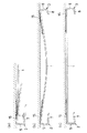
例えば、この種のティッシュケースホルダーとして、実開昭61−183825号公報(第1従来例)には、図12に示すように、壁面等に取り付ける基材50に上向きにフック51を設け、ティッシュケース52に形成した穴にフック51の鉤先部を差し込み、ティッシュケース52を下方へスライドさせてセットするものが記載されている。
【0003】
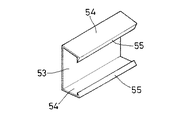
また、実開昭60−48792号公報(第2従来例)には、図13に示すように、背板53の上下に抱込板54を連設し、その先端に表面が内側へ傾斜した鉤先部55を設け、抱込板54を撓ませつつ、ティッシュケースを押し込むようにしてセットするものが記載されている。
【0004】
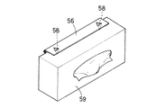
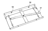
また、実開昭60−145894号公報(第3従来例)及び実開平4−7482号公報(第4従来例)には、それぞれ図14及び図15に示すように、蝶番板56の回動又はレバー57の操作に伴い、尖頭58をティッシュケース59に上下から突き刺して、ティッシュケース59をセットするものが記載されている。
【0005】
【発明が解決しようとする課題】
しかしながら、第1従来例のティッシュケースホルダーでは、ティッシュケース52を差し込むため、フック51の鉤先部と基材50との間にある程度の隙間が必要であり、この隙間により、ティッシュケース52ががたつく恐れがある。
【0006】
また、第2従来例のティッシュケースホルダーでは、抱込板54を撓ませるのに大きな力を要し、ティッシュケースをセットしにくいという問題があるほか、壁面等に取り付ける向きが限定されるという問題もある。
【0007】
また、第3及び第4従来例のティッシュケースホルダーでは、尖頭58を上下させる機構が必要となり、構造が複雑化するという問題がある。
【0008】
そこで、この発明は、簡単な構造で、ティッシュケースを容易かつ堅固にセットできるティッシュケースホルダーを提供することを課題とする。
【0009】
【課題を解決するための手段】
上記課題を解決するため、この発明に係るティッシュケースホルダーは、壁面等に取り付けられる基材に、鉤先部の長さが異なる一対のフックを設け、長い鉤先部の裏面を先端へかけて基材側へ傾斜させると共に、短い鉤先部の裏面を基端へかけて基材側へ傾斜させ、ティッシュケースの両端の解体用穴に各フックの鉤先部を順次差し込み、ティッシュケースを短い鉤先部の基端側へスライドさせると、鉤先部の傾斜により、ティッシュケースが基材に密着して保持されるようにしたのである。
【0010】
また、長い鉤先部と基材の間に、ティッシュケースのスライドを阻止するアタッチメントを抜差自在に挿入し、壁面等に横向きに取り付けても、ティッシュケースが脱落しないようにしたのである。
【0011】
また、細長いプラスチック製の板材を折り曲げて、前記基材と一対のフックとを形成することにより、コンパクト化及び低コスト化を図ったのである。
【0012】
さらに、前記基材の裏面に、両端側へ尖端を向けた針をやや浮かせて設けることにより、基材を撓ませつつ、車の内装材等に針を刺し込んで、取り付けられるようにしたのである。
【0013】
【発明の実施の形態】
以下、この発明の実施の形態を添付図面に基づいて説明する。
【0014】
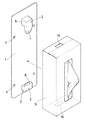
図1及び図2は,この発明の一実施形態を示す。このティッシュケースホルダーは、縦長の板状基材1に上下一対のフック2,3を設けたものであり、基材1には、壁面等への取付のため、ビス穴4が設けられている。基材1の形状は、特に限定されず、表面に広告等を印刷しておいてもよい。
【0015】
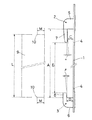
前記フック2,3は、基部5,6から鉤先部7,8が向き合うように屈曲したものであり、この基部5,6の間隔Aは、ティッシュケース9の長さLよりも大きく、鉤先部7は鉤先部8よりも長く、鉤先部7,8の先端の間隔Bは、ティッシュケース9の長さLよりも小さくなっている。
【0016】
また、鉤先部7の裏面は、先端(下方)へかけて∠αだけ基材1側に傾斜し、鉤先部8の裏面は、基端(下方)へかけて∠βだけ基材1側に傾斜している。
【0017】
そして、鉤先部7の先端部(下部)と基材1との間隔C及び鉤先部8の基端部(下部)と基材1との間隔Dは、ティッシュケース9の両端に形成される解体用穴10と底面との距離Mよりもやや小さくなっている。
【0018】
このようなティッシュケースホルダーを使用する際には、図3(a)に示すようにビス11を用いて、或いは、基材1の裏面に貼り付けた両面粘着テープを用いて、基材1を壁面等へ予め固定しておく。また、金属面へは、基材1の裏面に貼り付けた磁石で固定してもよい。
【0019】
一方、図1に示すように、ティッシュケース9の両端面には、解体用穴10を開口させておく。この解体用穴10は、現在流通している殆どのティッシュケースに、ほぼ同じ位置に設けられている。
【0020】
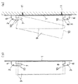
そして、図3(a)に示すように、ティッシュケース9を傾けつつ、上方の解体用穴10にフック2の鉤先部7を差し込み、次いで、ティッシュケース9を垂直に戻して、下方の解体用穴10にフック3の鉤先部8を差し込む。
【0021】
その後、図3(b)に示すように、ティッシュケース9を下方へスライドさせると、鉤先部7,8の裏面の傾斜により、ティッシュケース9は、基材1に引き寄せられて密着する。
【0022】
このように、上記ティッシュケースホルダーでは、ティッシュケース9の両端の解体用穴10を利用して、ティッシュケース9を容易にセットでき、その状態において、ティッシュケース9ががたつくこともない。
【0023】
また、このティッシュケースホルダーは、基材1にフック2,3を設けただけの簡単な構造であることから、製造にコストもかからない。
【0024】
なお、ティッシュケース9の高さや長さが多少異なっても、解体用穴10の底面からの距離Mさえほぼ一定であれば、ティッシュケース9は問題なくセットでき、使用上の障害とはならない。
【0025】
次に、この発明の他の実施形態を図4に示す。このティッシュケースホルダーは、細長いプラスチック製の板材を折り曲げて、基材1及びフック2,3を形成することにより、コンパクト化及び低コスト化を図ったものである。なお、この例では、基材1の裏面に、金属面へ固定するための磁石11を貼り付けている。
【0026】
ところで、このようなティッシュケースホルダーを壁面等に横向きに取り付けると、ティッシュケース9が長い鉤先部7の基端側へスライドし、短い鉤先部8が解体用穴10から抜け出して、ティッシュケース9が脱落することがある。
【0027】
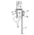
このような現象を防止するには、図5に示すように、フック2の鉤先部7と基材1の間に、アタッチメント12を挿入する。
【0028】
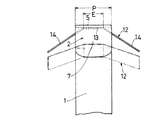
このアタッチメント12は、弾性を有するプラスチック製の板材を材料とし、その板材の両側部を同一面側へ塑性変形させて折り曲げることにより、中間部13の両側に斜め外方へ向かう翼片14を連設したものである。
【0029】
ここで、図6及び図7に示すように、アタッチメント12の中間部13の長さEは、基材1の幅Pよりも小さくなっており、板材の幅Fは、鉤先部7の先端部と基材1との最小間隔Qよりも大きく、かつ、鉤先部7の基端部と基材1との間隔Rよりやや小さくなっている。
【0030】
このようなアタッチメント12を鉤先部7と基材1の間に挿入するには、図中鎖線で示すように、アタッチメント12を傾けつつ、鉤先部7の先端部と基材1の間を通過させ、中間部13を鉤先部7の基端側へ挿入した後、アタッチメント12の傾きを戻す。
【0031】
これにより、アタッチメント12は、鉤先部7と基材1の間から抜け止めされて、その姿勢も安定する。
【0032】
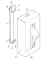
次いで、図8に示すように、ティッシュケース9をセットすると、ティッシュケース9の端面がアタッチメント12の翼片14により弾力的に押圧され、ティッシュケース9のスライドに伴う脱落が防止される。
【0033】
このように、アタッチメント12を使用することにより、この発明に係るティッシュケースホルダーでは、ティッシュケース9を縦横どちら向きにも取り付けることができる。
【0034】
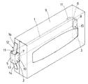
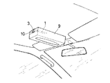
そのほか、このプラスチック製の板材から成るティッシュケースホルダーは、図9に示すように、自動車の車内などにおいて、ルーフ内面等、布の内装材が張られた部分や幌の部分に取り付けることもできる。
【0035】
この場合、図10に示すように、基材1の裏面に、両端側へ尖端を向けた針15をやや浮かせて設けておく。針15は、各端二本ずつ設けると、取付時の安定性が向上する。また、このティッシュケースホルダーを車内等に横向きに取り付ける場合には、フック2にアタッチメント12を嵌めておく。
【0036】
この取り付けに際しては、まず、図11(a)に示すように、一方の針15を内装材等に刺し込み、次に、図11(b)に示すように、基材1を撓ませつつ、他方の針15を内装材等に刺し込む。そして、基材1を弾力で復元させると、図11(c)に示すように、両方の針15が内装材等から抜け止めされる。
【0037】
このようにして、例えば、車内の天井前部にティッシュケースホルダーを取り付け、ティッシュケースをセットすると、運転席や助手席に座っていても、容易にティッシュペーパーを取り出すことができ、わき見運転による事故を防止することができる。
【0038】
また、針15は車の内装材の繊維の織目に刺し込まれるので、ティッシュケースホルダーを取り外したとき、目立つ傷や汚れが残ることがない。
【0039】
【発明の効果】
以上のように、この発明に係るティッシュケースホルダーは、基材に一対のフックを設けた簡単な構造であることから、安価に製造でき、各フックの鉤先部をティッシュケースの両端の解体用穴に順次差し込み、ティッシュケースをスライドさせるだけで、容易かつ堅固にティッシュケースをセットできる。
【0040】
また、フックの鉤先部と基材の間に、ティッシュケースのスライドを阻止するアタッチメントを挿入すると、壁面等に横向きに取り付けても、ティッシュケースが脱落しなくなる。
【0041】
また、細長いプラスチック製の板材を折り曲げて、基材と一対のフックとを形成すると、コンパクト化及び低コスト化を図ることができる。
【0042】
さらに、基材の裏面に、両端側へ尖端を向けた針をやや浮かせて設けると、基材を撓ませつつ、車の内装材等に針を刺し込んで、ティッシュペーパーを取り出しやすい位置に取り付けることができ、わき見運転による事故を防止できる。
【図面の簡単な説明】
【図1】この発明の一実施形態に係るティッシュケースホルダーの斜視図
【図2】同上の側面図
【図3】(a)同上のティッシュケース取付過程を示す一部縦断側面図
(b)同上の次の過程を示す側面図
【図4】この発明の他の実施形態に係るティッシュケースホルダーの斜視図
【図5】同上のアタッチメントの装着状態を示す横向きの斜視図
【図6】同上のアタッチメントの装着過程を示すフック部分の拡大正面図
【図7】同上の縦断側面図
【図8】同上のティッシュケースのセット状態を示す斜視図
【図9】同上のティッシュケースホルダーの車内への取付状態を示す斜視図
【図10】同上の取付用の針を設けた状態を示す斜視図
【図11】(a)同上の取付過程の第1状態を示す端部側面図
(b)同上の取付過程の第2状態を示す側面図
(c)同上の取付状態を示す側面図
【図12】第1従来例を示す斜視図
【図13】第2従来例を示す斜視図
【図14】第3従来例を示す斜視図
【図15】第4従来例を示す斜視図
【符号の説明】
1 基材
2,3 フック
5,6 基部
7,8 鉤先部
9 ティッシュケース
10 解体用穴
12 アタッチメント
13 中間部
14 翼片
15 針[0001]
TECHNICAL FIELD OF THE INVENTION
The present invention relates to a tissue case holder for attaching a tissue case to a wall or the like.
[0002]
[Prior art]
For example, Japanese Unexamined Utility Model Publication No. 61-183825 (first conventional example) discloses a tissue case holder of this type, in which a
[0003]
In Japanese Utility Model Laid-Open Publication No. 60-48792 (second conventional example), as shown in FIG. 13,
[0004]
Further, in Japanese Utility Model Laid-Open No. 60-145894 (third conventional example) and Japanese Utility Model Laid-Open No. 4-7482 (fourth conventional example), as shown in FIGS. Alternatively, a description is given of setting the
[0005]
[Problems to be solved by the invention]
However, in the tissue case holder of the first conventional example, a certain gap is required between the hook portion of the
[0006]
Further, in the tissue case holder of the second conventional example, a large force is required to bend the
[0007]
In the tissue case holders of the third and fourth conventional examples, a mechanism for raising and lowering the
[0008]
Therefore, an object of the present invention is to provide a tissue case holder that can easily and firmly set a tissue case with a simple structure.
[0009]
[Means for Solving the Problems]
In order to solve the above-mentioned problems, a tissue case holder according to the present invention provides a pair of hooks having different hook-tip lengths on a base material attached to a wall surface or the like, and extends the back surface of the long hook-tip toward the tip. While tilting to the base material side, tilt the back surface of the short hook tip toward the base end toward the base material, insert the hook tips of each hook sequentially into the disassembly holes at both ends of the tissue case, shorten the tissue case When the hook is slid toward the base end, the tissue is held in close contact with the base material due to the inclination of the hook.
[0010]
Also, an attachment for preventing the tissue case from sliding is inserted between the long hook portion and the base material so that the tissue case does not fall off even if the attachment is mounted sideways on a wall or the like.
[0011]
Further, by bending an elongated plastic plate to form the base and the pair of hooks, the size and cost are reduced.
[0012]
Furthermore, by providing a needle with the tip pointed toward both ends slightly floating on the back surface of the base material, the base material is bent, and the needle is inserted into an interior material of a car and the like, so that it can be attached. is there.
[0013]
BEST MODE FOR CARRYING OUT THE INVENTION
Hereinafter, embodiments of the present invention will be described with reference to the accompanying drawings.
[0014]
1 and 2 show an embodiment of the present invention. This tissue case holder is provided with a pair of upper and
[0015]
The
[0016]
The back surface of the
[0017]
A distance C between the tip (lower part) of the
[0018]
When such a tissue case holder is used, the
[0019]
On the other hand, as shown in FIG. 1, dismantling
[0020]
Then, as shown in FIG. 3 (a), the
[0021]
Thereafter, as shown in FIG. 3B, when the
[0022]
As described above, in the above-described tissue case holder, the
[0023]
In addition, since the tissue case holder has a simple structure in which the
[0024]
Even if the height and length of the
[0025]
Next, another embodiment of the present invention is shown in FIG. This tissue case holder is formed by bending a long and thin plastic plate material to form the
[0026]
By the way, when such a tissue case holder is mounted laterally on a wall surface or the like, the
[0027]
In order to prevent such a phenomenon, as shown in FIG. 5, the
[0028]
This
[0029]
Here, as shown in FIGS. 6 and 7, the length E of the
[0030]
In order to insert such an
[0031]
As a result, the
[0032]
Next, as shown in FIG. 8, when the
[0033]
As described above, by using the
[0034]
In addition, as shown in FIG. 9, the tissue case holder made of a plastic plate material can be attached to a portion covered with a cloth interior material or a hood portion, such as an inner surface of a roof, in an automobile or the like.
[0035]
In this case, as shown in FIG. 10, a
[0036]
In this attachment, first, as shown in FIG. 11A, one of the
[0037]
In this way, for example, if you attach the tissue case holder to the front of the ceiling in the car and set the tissue case, you can easily take out the tissue paper even if you are sitting in the driver's seat or the passenger's seat, Can be prevented.
[0038]
Further, since the
[0039]
【The invention's effect】
As described above, the tissue case holder according to the present invention has a simple structure in which a pair of hooks are provided on the base material, so that it can be manufactured at low cost, and the hooks of each hook are used for dismantling both ends of the tissue case. The tissue case can be easily and firmly set by simply inserting the tissue case into the holes and sliding the tissue case.
[0040]
In addition, if an attachment that prevents the tissue case from sliding is inserted between the hook tip of the hook and the base material, the tissue case will not fall off even if it is mounted horizontally on a wall or the like.
[0041]
In addition, by bending an elongated plastic plate to form a base and a pair of hooks, it is possible to reduce the size and cost.
[0042]
In addition, if the needle with the pointed end facing the both ends is slightly floated on the back of the base material, the needle is stabbed into the interior material of the car while bending the base material, and the tissue paper is attached at a position where it can be easily taken out It is possible to prevent accidents caused by driving aside.
[Brief description of the drawings]
FIG. 1 is a perspective view of a tissue case holder according to an embodiment of the present invention. FIG. 2 is a side view of the same. FIG. FIG. 4 is a perspective view of a tissue case holder according to another embodiment of the present invention; FIG. 5 is a lateral perspective view showing a mounted state of the attachment; Enlarged front view of the hook part showing the mounting process of FIG. 7 FIG. 7 is a longitudinal sectional side view of the same. FIG. 8 is a perspective view showing a set state of the same tissue case. FIG. 9 is an attached state of the same tissue case holder in the vehicle. FIG. 10 is a perspective view showing a state where the same mounting needle is provided. FIG. 11 (a) is an end side view showing a first state of the same mounting step. Side showing the second state of (C) Side view showing the mounting state of the above. FIG. 12 is a perspective view showing a first conventional example. FIG. 13 is a perspective view showing a second conventional example. FIG. 14 is a perspective view showing a third conventional example. Perspective view showing a fourth conventional example.
Claims (4)
Priority Applications (6)
| Application Number | Priority Date | Filing Date | Title |
|---|---|---|---|
| JP2002098559A JP3598103B2 (en) | 2001-07-31 | 2002-04-01 | Tissue case holder |
| US10/207,272 US6641100B2 (en) | 2001-07-31 | 2002-07-30 | Tissue case holder |
| EP02017148A EP1281342B1 (en) | 2001-07-31 | 2002-07-30 | Tissue case holder |
| AT02017148T ATE304807T1 (en) | 2001-07-31 | 2002-07-30 | HOLDER FOR TISSUE DISPENSER CAN |
| DE60206224T DE60206224T2 (en) | 2001-07-31 | 2002-07-30 | Holder for cloth dispenser |
| CN02141599.4A CN1240588C (en) | 2001-07-31 | 2002-07-31 | Thin-paper box fixing device |
Applications Claiming Priority (3)
| Application Number | Priority Date | Filing Date | Title |
|---|---|---|---|
| JP2001230865A JP2002128163A (en) | 2001-07-31 | 2001-07-31 | Tissue case holder |
| JP2001-230865 | 2001-07-31 | ||
| JP2002098559A JP3598103B2 (en) | 2001-07-31 | 2002-04-01 | Tissue case holder |
Publications (2)
| Publication Number | Publication Date |
|---|---|
| JP2003112787A JP2003112787A (en) | 2003-04-18 |
| JP3598103B2 true JP3598103B2 (en) | 2004-12-08 |
Family
ID=26619615
Family Applications (1)
| Application Number | Title | Priority Date | Filing Date |
|---|---|---|---|
| JP2002098559A Expired - Fee Related JP3598103B2 (en) | 2001-07-31 | 2002-04-01 | Tissue case holder |
Country Status (6)
| Country | Link |
|---|---|
| US (1) | US6641100B2 (en) |
| EP (1) | EP1281342B1 (en) |
| JP (1) | JP3598103B2 (en) |
| CN (1) | CN1240588C (en) |
| AT (1) | ATE304807T1 (en) |
| DE (1) | DE60206224T2 (en) |
Families Citing this family (31)
| Publication number | Priority date | Publication date | Assignee | Title |
|---|---|---|---|---|
| EP1565391A2 (en) * | 2002-11-27 | 2005-08-24 | S. C. Johnson Home Storage, Inc. | Holding device |
| US20040211871A1 (en) * | 2002-11-27 | 2004-10-28 | Turvey Robert R. | Method and device for suspending boxes |
| US6769658B2 (en) * | 2002-12-19 | 2004-08-03 | James R. Stokes | Remote control holder device |
| US20050199770A1 (en) * | 2003-05-01 | 2005-09-15 | Andrews Michael L. | Floor located vehicle container holder |
| US20040245421A1 (en) * | 2003-06-09 | 2004-12-09 | Turvey Robert R. | Method and device for holding boxes |
| US20050035126A1 (en) * | 2003-06-25 | 2005-02-17 | Ron Serio | Mountable container system |
| USD519368S1 (en) | 2005-01-31 | 2006-04-25 | S.C. Johnson Home Storage, Inc. | Swivel slider body with handle |
| WO2007065148A2 (en) * | 2005-12-02 | 2007-06-07 | Pera Odishoo | Mountable box holder and method for mounting a box |
| US20100038329A1 (en) * | 2008-08-12 | 2010-02-18 | Chin-Chi Pan | Decorative wall mount |
| US20100051576A1 (en) * | 2008-09-04 | 2010-03-04 | Tran Quoc A | Container cap with aqua tissue |
| US20110070018A1 (en) * | 2009-09-23 | 2011-03-24 | Ford Global Technologies, Llc | System for attaching an accessory to vehicle interior |
| US8444008B2 (en) * | 2010-03-16 | 2013-05-21 | Khaled Abdullah M. Al-Mahnna | Tissue holder and dispenser |
| RU2549976C2 (en) * | 2010-12-21 | 2015-05-10 | Ска Хайджин Продактс Аб | Device for dosaged supply containing holder and package for contents dosaged supply |
| US20120273513A1 (en) * | 2011-04-28 | 2012-11-01 | Jerry Ray Stephens | Dispensers for sanitary tissue products |
| US8602373B2 (en) * | 2011-07-25 | 2013-12-10 | Mark Beckey | Hangable cup holders |
| JP2015044596A (en) * | 2013-08-27 | 2015-03-12 | 俊孝 栗原 | Tissue box holder |
| JP6042318B2 (en) * | 2013-12-06 | 2016-12-14 | ニチレイマグネット株式会社 | Goods storage case fixture |
| DE102013021395A1 (en) * | 2013-12-13 | 2015-06-18 | Daimler Ag | Holding device, in particular cloth box holder, for a cloth box |
| USD781742S1 (en) | 2014-12-12 | 2017-03-21 | Alex And Ani, Llc | Slider for article of jewelry |
| USD785483S1 (en) | 2015-03-26 | 2017-05-02 | Alex And Ani, Llc | Article of jewelry |
| USD785485S1 (en) | 2015-03-26 | 2017-05-02 | Alex And Ani, Llc | Article of jewelry |
| USD786118S1 (en) | 2015-03-26 | 2017-05-09 | Alex And Ani, Llc | Article of jewelry |
| US10123594B2 (en) | 2015-08-07 | 2018-11-13 | Alex And Ani, Llc | Slider elements for articles of jewelry |
| USD809421S1 (en) | 2015-08-07 | 2018-02-06 | Alex And Ani, Llc | Slider for articles of jewelry |
| USD853749S1 (en) | 2018-04-24 | 2019-07-16 | Edward L. Kostjal | Holder for tissue box |
| US11021860B1 (en) * | 2019-11-19 | 2021-06-01 | Marvin Thomas | Toilet tank support |
| JP7361392B2 (en) * | 2020-03-31 | 2023-10-16 | 常雄 竹内 | A holder that can be moved 360 degrees on a flat surface and can be fixed using a magnet that can be detachably attached to a flat surface such as a wall that sticks to a magnet. |
| USD957924S1 (en) | 2021-05-20 | 2022-07-19 | James Hofer | Wall bracket |
| GB202112135D0 (en) * | 2021-08-24 | 2021-10-06 | Balco Global Ltd | Dispenser |
| EP4238458A1 (en) | 2022-03-02 | 2023-09-06 | InterDesign, Inc. | Brackets for bins and shelves |
| USD1018115S1 (en) * | 2023-08-11 | 2024-03-19 | Zekai Yu | Grocery bag dispenser |
Family Cites Families (26)
| Publication number | Priority date | Publication date | Assignee | Title |
|---|---|---|---|---|
| US1306272A (en) * | 1919-06-10 | Wall-hanger for radiators | ||
| US1170414A (en) * | 1915-03-24 | 1916-02-01 | George H Christensen | Receptacle-holder. |
| US1227165A (en) * | 1915-09-24 | 1917-05-22 | William Marin | Bracket. |
| US2155760A (en) * | 1937-04-01 | 1939-04-25 | Hy Joseph | Box holder |
| US2104612A (en) * | 1937-07-14 | 1938-01-04 | Henry E Droll | Supporting pin for eyeglasses and the like |
| US2263956A (en) * | 1939-12-05 | 1941-11-25 | Linus E Russell | Package holder |
| US2325712A (en) * | 1943-02-06 | 1943-08-03 | Leonard G Shurmur | Container holder |
| US2697572A (en) * | 1949-11-30 | 1954-12-21 | Pfankuch Joseph Edward | Adjustable hanger |
| US2986366A (en) * | 1959-06-18 | 1961-05-30 | George T Wesson | Support for television cabinets and the like |
| US2991036A (en) * | 1960-01-11 | 1961-07-04 | Morgan James Russell | Magnetic box holding bracket |
| US3176943A (en) * | 1963-02-25 | 1965-04-06 | Robert S Hughes | Holders for paintings |
| US3285559A (en) * | 1965-03-03 | 1966-11-15 | Edward J Simon | Dispenser holders |
| US3837608A (en) * | 1972-08-09 | 1974-09-24 | E Simon | Dispenser holder |
| CH657514A5 (en) | 1981-11-21 | 1986-09-15 | Elsa Dorothea Achermann Gertsc | Device for suspending lid-like covering plates for cooking points |
| JPS60145894A (en) | 1984-01-10 | 1985-08-01 | トツパン・ム−ア株式会社 | How to create a bill with a barcode label |
| JPS61183825A (en) | 1985-02-08 | 1986-08-16 | キヤノン株式会社 | Keyboard unit |
| JPH0245153Y2 (en) * | 1985-05-08 | 1990-11-29 | ||
| US5207403A (en) * | 1989-11-07 | 1993-05-04 | Penniman David T | Device and method to support polyethylene or other sheeting |
| US5246251A (en) * | 1991-06-24 | 1993-09-21 | Ronnie Evans | Book holder |
| US5494250A (en) * | 1994-07-29 | 1996-02-27 | Chen; Wen-Yen | Cleaning tissue holder |
| JPH10201659A (en) * | 1997-01-20 | 1998-08-04 | Goyo Spring:Kk | Tissue box mounting tool |
| US5996953A (en) * | 1998-02-20 | 1999-12-07 | Andrew Corporation | Mounting assembly for mobile electronic equipment |
| CA2258381A1 (en) * | 1999-01-07 | 2000-07-07 | Charles A. Annand | Tissue box holder |
| US6543737B2 (en) * | 2001-02-20 | 2003-04-08 | Clayton O. Decker | Tissue box holder |
| JP2002263031A (en) * | 2001-03-07 | 2002-09-17 | Takeshi Imai | Tissue box holder |
| JP3949403B2 (en) * | 2001-06-13 | 2007-07-25 | ニチレイマグネット株式会社 | Box holder and its mounting structure |
-
2002
- 2002-04-01 JP JP2002098559A patent/JP3598103B2/en not_active Expired - Fee Related
- 2002-07-30 EP EP02017148A patent/EP1281342B1/en not_active Expired - Lifetime
- 2002-07-30 US US10/207,272 patent/US6641100B2/en not_active Expired - Fee Related
- 2002-07-30 AT AT02017148T patent/ATE304807T1/en not_active IP Right Cessation
- 2002-07-30 DE DE60206224T patent/DE60206224T2/en not_active Expired - Fee Related
- 2002-07-31 CN CN02141599.4A patent/CN1240588C/en not_active Expired - Fee Related
Also Published As
| Publication number | Publication date |
|---|---|
| US20030025057A1 (en) | 2003-02-06 |
| ATE304807T1 (en) | 2005-10-15 |
| DE60206224T2 (en) | 2006-06-22 |
| US6641100B2 (en) | 2003-11-04 |
| EP1281342B1 (en) | 2005-09-21 |
| EP1281342A1 (en) | 2003-02-05 |
| CN1240588C (en) | 2006-02-08 |
| CN1405067A (en) | 2003-03-26 |
| DE60206224D1 (en) | 2006-02-02 |
| JP2003112787A (en) | 2003-04-18 |
Similar Documents
| Publication | Publication Date | Title |
|---|---|---|
| JP3598103B2 (en) | Tissue case holder | |
| JP3203238U (en) | Wall-mounted structure | |
| WO2007008277A2 (en) | Vehicle window lift plate | |
| JP2000159038A (en) | Mounting structure of bumper and grill | |
| KR200388711Y1 (en) | Layer for advertising medi | |
| EP2166428B1 (en) | Stand attachment structure | |
| JP3980845B2 (en) | Panel mounting structure to base material in synthetic resin molded product | |
| JP3879711B2 (en) | Wall panel mounting structure | |
| JP2848780B2 (en) | Article attachment | |
| CN223886646U (en) | Hook device | |
| JP4422275B2 (en) | Snow stopper | |
| JP3580204B2 (en) | Member mounting structure | |
| JP2002128163A (en) | Tissue case holder | |
| CN220518141U (en) | Head-up display assembly and vehicle | |
| JP2005207162A (en) | Screen fastening plate mounting mechanism for curtain device | |
| CN110329174A (en) | Cresting item installs buckle structure | |
| JP4033653B2 (en) | Boards such as writing boards | |
| KR200317794Y1 (en) | Multi-function Room-mirror for Automobile | |
| JP7140369B2 (en) | Used car sales price display device | |
| JP2005095637A (en) | Bulletin board fixture and bulletin board using the bulletin board fixture | |
| JP3021240U (en) | Suspension of goods | |
| JPH11299602A (en) | Fitting structure of price card holder to rack | |
| JP2002358037A (en) | Flag set | |
| JP2008093311A (en) | Lock unit | |
| JPH10337229A (en) | Shelf receiving device |
Legal Events
| Date | Code | Title | Description |
|---|---|---|---|
| A977 | Report on retrieval |
Free format text: JAPANESE INTERMEDIATE CODE: A971007 Effective date: 20040811 |
|
| TRDD | Decision of grant or rejection written | ||
| A01 | Written decision to grant a patent or to grant a registration (utility model) |
Free format text: JAPANESE INTERMEDIATE CODE: A01 Effective date: 20040817 |
|
| A61 | First payment of annual fees (during grant procedure) |
Free format text: JAPANESE INTERMEDIATE CODE: A61 Effective date: 20040910 |
|
| R150 | Certificate of patent or registration of utility model |
Free format text: JAPANESE INTERMEDIATE CODE: R150 |
|
| FPAY | Renewal fee payment (event date is renewal date of database) |
Free format text: PAYMENT UNTIL: 20080917 Year of fee payment: 4 |
|
| FPAY | Renewal fee payment (event date is renewal date of database) |
Free format text: PAYMENT UNTIL: 20080917 Year of fee payment: 4 |
|
| FPAY | Renewal fee payment (event date is renewal date of database) |
Free format text: PAYMENT UNTIL: 20090917 Year of fee payment: 5 |
|
| FPAY | Renewal fee payment (event date is renewal date of database) |
Free format text: PAYMENT UNTIL: 20100917 Year of fee payment: 6 |
|
| FPAY | Renewal fee payment (event date is renewal date of database) |
Free format text: PAYMENT UNTIL: 20100917 Year of fee payment: 6 |
|
| FPAY | Renewal fee payment (event date is renewal date of database) |
Free format text: PAYMENT UNTIL: 20110917 Year of fee payment: 7 |
|
| FPAY | Renewal fee payment (event date is renewal date of database) |
Free format text: PAYMENT UNTIL: 20120917 Year of fee payment: 8 |
|
| FPAY | Renewal fee payment (event date is renewal date of database) |
Free format text: PAYMENT UNTIL: 20130917 Year of fee payment: 9 |
|
| R250 | Receipt of annual fees |
Free format text: JAPANESE INTERMEDIATE CODE: R250 |
|
| R250 | Receipt of annual fees |
Free format text: JAPANESE INTERMEDIATE CODE: R250 |
|
| R250 | Receipt of annual fees |
Free format text: JAPANESE INTERMEDIATE CODE: R250 |
|
| LAPS | Cancellation because of no payment of annual fees |