JP3597467B2 - 2-pole step motor for watches - Google Patents
2-pole step motor for watches Download PDFInfo
- Publication number
- JP3597467B2 JP3597467B2 JP2000553874A JP2000553874A JP3597467B2 JP 3597467 B2 JP3597467 B2 JP 3597467B2 JP 2000553874 A JP2000553874 A JP 2000553874A JP 2000553874 A JP2000553874 A JP 2000553874A JP 3597467 B2 JP3597467 B2 JP 3597467B2
- Authority
- JP
- Japan
- Prior art keywords
- stator
- rotor
- holding torque
- recesses
- step motor
- Prior art date
- Legal status (The legal status is an assumption and is not a legal conclusion. Google has not performed a legal analysis and makes no representation as to the accuracy of the status listed.)
- Expired - Lifetime
Links
Images


Classifications
-
- G—PHYSICS
- G04—HOROLOGY
- G04C—ELECTROMECHANICAL CLOCKS OR WATCHES
- G04C13/00—Driving mechanisms for clocks by master-clocks
- G04C13/08—Slave-clocks actuated intermittently
- G04C13/10—Slave-clocks actuated intermittently by electromechanical step advancing mechanisms
- G04C13/11—Slave-clocks actuated intermittently by electromechanical step advancing mechanisms with rotating armature
-
- H—ELECTRICITY
- H02—GENERATION; CONVERSION OR DISTRIBUTION OF ELECTRIC POWER
- H02K—DYNAMO-ELECTRIC MACHINES
- H02K37/00—Motors with rotor rotating step by step and without interrupter or commutator driven by the rotor, e.g. stepping motors
- H02K37/10—Motors with rotor rotating step by step and without interrupter or commutator driven by the rotor, e.g. stepping motors of permanent magnet type
- H02K37/12—Motors with rotor rotating step by step and without interrupter or commutator driven by the rotor, e.g. stepping motors of permanent magnet type with stationary armatures and rotating magnets
- H02K37/14—Motors with rotor rotating step by step and without interrupter or commutator driven by the rotor, e.g. stepping motors of permanent magnet type with stationary armatures and rotating magnets with magnets rotating within the armatures
- H02K37/16—Motors with rotor rotating step by step and without interrupter or commutator driven by the rotor, e.g. stepping motors of permanent magnet type with stationary armatures and rotating magnets with magnets rotating within the armatures having horseshoe armature cores
Description
【0001】
【発明の属する技術分野】
この発明は、アナログ式電子時計に用いる時計用の2極式ステップモータに関する。
【0002】
【従来の技術】
アナログ式電子時計は、動力源に電池を用いているので、ある期間使用を続けると電池切れになって機能を停止してしまう。そのため、定期的に電池を交換しなければならないので、それが使用者にとっては大変煩わしかった。
そして、その電池の交換作業は、専門の業者に頼まなければならないので、使用したいときに電池切れを起こしてしまったときには、すぐに電池を交換することができないため非常に不便であった。
【0003】
このように、アナログ式電子時計の電池切れは使用者にとって大きな問題であるため、近年ではこのようなアナログ式電子時計における電池の長寿命化の検討や、携帯中に使用者の運動に伴って動作する発電機を時計内に内蔵したり、太陽電池などの発電機構を内蔵させて、電池交換を完全に不要にする時計の開発が行われている。
しかしながら、このような発電機構内蔵式のアナログ式電子時計は、内蔵しているコンデンサもしくは二次電池に蓄えられている電力で時計を駆動するようにしているが、使用者によって時計を使用する条件が異なるため、必要で十分な電力を常時発電するのが難しくなる場合があった。
【0004】
そのため、時計を使用中に停止させずに安定して動作させるようにするためには、このような発電機構内蔵式の時計においても低消費電力化を図る必要があった。
一方、電池に関しては、サイズが大きくて容量の大きな電池を用いることができれば長寿命化が図れるが、時計のデザイン上の制約から電池のサイズをあまり大きくすることはできないということがあった。したがって、電池の長寿命化を図ろうとすれば、時計側で消費電力を低減する必要があった。
【0005】
ここで、アナログ式電子時計の機構を概略説明すると、水晶振動子などで発生させた基準信号にしたがって時計用の2極式ステップモータを間欠駆動し、ステップモータの運動を歯車を介して指針に伝えることにより時刻表示を行う構造である。
そのため、このようなアナログ式電子時計では、大別して水晶振動子などを含んでいて基準信号を発生する回路部分と、指針を回転させるステップモータの部分で電力が消費される。
【0006】
ところが、現在のアナログ式電子時計においては、回路部分は半導体集積回路化されて消費電力が小さくなっているので、結局電力の大部分は運針のためのステップモータの駆動に消費される。そのため、そのステップモータの消費電力の低減が、時計全体の低消費電力化に与える効果が大きい。
図22は従来の時計用の2極式ステップモータの概略構造を示す平面図である。
この時計用の2極式ステップモータ(以下単に「ステップモータ」とも云う)は、高透磁率の材料で形成された磁芯7aに導線7bを巻回したコイル7と、そのコイル7の磁芯7aの両端にネジ8,8によりそれぞれ結合されて磁気的に接続されたステータ201とを有している。
【0007】
そのステータ201には、ほぼ中央にロータ穴202が形成してあり、そのロータ穴202の中にロータ3が回転可能に配設されている。
そのロータ3は、ロータ磁石3aとロータ軸3bとからなり、ロータ磁石3aは強磁性材料で作られて丈の低い円柱状に形成されている。そして、そのロータ磁石3aの中心に形成した軸穴に、回転軸となるロータ軸3bを、紙面に対して垂直な方向にはめ込んで一体にし、ロータ磁石3aを直径方向に2極に着磁している。
【0008】
そのロータ3は、ロータ軸3bの両端部が図示を省略している軸受によりそれぞれ回転自在に支持されていて、ロータ穴202の中心に位置している。そのロータ軸3bの端部には歯車が形成されていて、その歯車を介して回転運動が時計の指針に伝達される構成になっている。
さらに、ロータ穴202の内周には保持トルク設定手段を設けて、その保持トルク設定手段によりステップモータの非駆動時に、ロータ磁石3aの磁極が初期位相角θ1 の一定の方向に位置するようにし、その位置でロータ3を所定の保持トルクで停止保持させている。
【0009】
このステップモータは、駆動電圧を印加してコイル7に正、負の電流を交互に流すことによってロータ穴202の内側に正負に応じた向きの磁界を、流した電流の大きさに対応させて発生させ、その磁界を予め着磁されているロータ磁石3aに作用させてロータ3を、図22で反時計回り方向に180゜(1ステップ)ずつ回転させる。
【0010】
次に、そのステップモータの1ステップの運動を説明する。
図22に示したコイル7に電流を流した場合に発生する磁束により、ロータ穴202の内部に生じる磁界の方向を励磁方向線12としたとき、コイル7に電流が流れていない状態では、ロータ磁石3aの磁極とステータ201の磁気作用により生じる保持トルク設定手段の保持トルクにより、ロータ3はロータ磁石3aの磁化の方向であり2つの磁極を結ぶ線4が、励磁方向線12に対して図22で反時計回り方向に初期位相角θ1 だけ回転した位置に保持されて停止している。
【0011】
この状態で、コイル7にロータ3が正転する方向の電流を流すと、コイル7に磁束が発生し、ロータ穴202の内部に磁界が生じて、ロータ3はこの磁界とロータ磁石3aの永久磁化量との相互作用により回転トルクを受け、上記保持トルクに抗して回転を始める。そして、コイル7には適当な時間だけ電流を流すと、ロータ3は次の停止位置まで180゜回転して停止する。
【0012】
ところで、このような構成のステップモータでは、その単位時間当たりの消費電力は、励磁用のコイル7に流す電流と印加する電池電圧の積で表される。そして、その際に印加される電池電圧はほぼ一定であるから、ステップモータの低消費電力化は、ステップモータに要求される駆動特性を満足しながら、いかにコイル7に流す電流を低減できるかにある。
また、このステップモータは、コイル7に電流を流してロータ3に回転トルクを発生させ、保持トルクに抗してロータ3を回転させるものであるので、保持トルクが小さければ回転トルクもそれに比例して小さくて済む。
【0013】
そのコイル7に流す電流は、回転トルクに比例するので保持トルクを減らすことができればコイル7に流す電流を小さくすることができ、その結果、時計用ステップモータの低消費電力化が図れる。
ところで、時計用ステップモータの保持トルクは、時計が落下等で衝撃を受けたときに針飛びを起こさないように指針を保持することによって正確な時間の表示ができるようにすると共に、時計内の軸受けや歯車に発生する摩擦トルクに抗して指針を正しい停止位置に落ち着かせる役割を果たすものである。
【0014】
したがって、低消費電力化を図るために単純に保持トルクを低減させればよいというものではなく、その保持トルクは時計の機能を維持するのに必要な最小限の保持トルクを満たすように設定する必要がある。
この時計に必要な保持トルクに関しては、国際公開WO 98/30939 号公報に開示されているように、衝撃により指針に生じる運動エネルギーが、ロータの持つ保持トルクによって生じる保持ポテンシャル、すなわち磁気ポテンシャルの差よりも小さければ針飛びは起こらない。
【0015】
そして、衝撃で指針が受け取る運動エネルギーは、指針の持つモーメントの2乗に比例するから、モーメントを小さくした指針を用いれば、保持ポテンシャル、すなわち保持トルクを小さくすることができる。
それによって、必要最小限の保持トルクを、通常の時計用ステップモータの保持トルクの数分の1程度の極めて小さな値に設定することが可能になり、ステップモータの低消費電力化が図れる。
【0016】
次に、従来の時計用ステップモータのステータに設けられている保持トルク設定手段について説明する。
従来の時計用ステップモータのステータに設けられている保持トルク設定手段としては、主に次に説明するような二つの構造のものがある。
その一つは、図22に示した時計用ステップモータにおけるステータ形状を図23に示すように、ステータ201は高透磁率の材料で形成されていて、その長手方向の両端にはそれぞれコイル7の磁芯7aの両端に結合するための穴6,6が形成されている。
【0017】
そのステータ201のほぼ中央に形成されているロータ穴202は、保持トルクと初期位相角θ1 (図22)を設定するために、互いに中心をずらした2つの半円を組み合わせた形状にしてある。
そして、その2つの半円をずらして組み合わせることにより、ギャップ量Gの2つの段差部204a、204bをそれぞれ形成している。このステータ201では、そのギャップ量Gを調節することによって保持トルクを所望の値に設定することができる。
【0018】
なお、このような段差部204a、204bをステータ201のロータ穴202に形成する構造は、例えば特開昭49−132507号公報に記載されている。
また、以後このようにステータのロータ穴に段差部を形成したステータを、ギャップ型ステータと呼ぶことにする。
【0019】
次に、図24を参照してもう一つの保持トルク設定手段の構造について説明する。なお、必要に応じて一部共通して使用する部品については、図22で説明した符号を使用して説明する。
このステータ211は、ロータ3の保持トルクと初期位相角を与えるための保持トルク設定手段として、ロータ穴212の内周に一対の凹部205a,205bをロータ穴212の中心軸に対して対称な位置に設けている。
そして、その凹部205a,205bのそれぞれ中心を通る直線24が、ロータ穴212の励磁の方向21に対して角度θ11だけ傾くようにしている。
【0020】
このステータ211では、凹部205a,205bの中心を通る直線24と、ロータ穴212の中心軸を通りステータ211の励磁方向に直角な直線27とのなす角度を、反時計回り方向を正の値とする凹部205a,205bの設置角度θ12として、その設置角度θ12を調節することによりロータ3の初期位相角θ1 (図22)を設定するようにしている。
そして、このようなステータ211の構造を持つ時計用ステップモータでは、一対の凹部205a,205bによりロータ3の保持トルクが定まる。
なお、このような凹部205a,205bをステータ211のロータ穴212に形成する構造は、例えば特開昭51−1908号公報に記載されている。
また、以後このようにステータのロータ穴に凹部を形成したステータを、ノッチ型ステータと呼ぶことにする。
【0021】
以上説明したように、従来のギャップ型ステータを使用したステップモータの場合には、ロータ穴の段差部のギャップ量を変えることによって保持トルクの大きさと初期位相角を調節することができる。
そこで、通常の時計用ステップモータでは、ロータ穴の平均直径が1700μm程度であるので、ステータの段差部のギャップ量を40〜50μm程度にすれば、最大保持トルクを300nNm前後に設定することができる。
【0022】
【発明が解決しようとする課題】
しかしながら、低消費電力化のために保持トルクを更に大幅に減らそうとすると、ギャップ量を10μm程度と極端に小さくしなければならないので、安定した保持トルクを生じさせるようにするのは、ステータの加工精度の点で難しくなる。
また、ギャップ量をこのように極端に小さくすると、それに連動して初期位相角(図22のθ1 参照)も小さくなってしまうため、ロータを駆動する際に大きな消費電力が必要となるため、結果として低消費電力化にならなくなってしまう。
【0023】
さらに、ギャップ型ステータの構造の場合には、ロータ穴の直径を大きくすることによって、同じギャップ量でありながら初期位相角を変えずに保持トルクを小さく設定することが可能であるが、このようにロータ穴の径を大きくすると、ロータ穴内に発生する磁界とロータ磁石との相互作用が減ってしまう。
すなわち、このようにすると電気機械結合係数が減少するため、コイルに電流を流すことによってロータに発生する回転トルクが小さくなってしまう。
【0024】
そのため、上記保持トルクにより形成される保持ポテンシャルを低減して初期位相角を適切に設定したとしても、電気機械結合係数の減少による回転トルクの低下分を補うために、コイルに流す電流を増やさなければならなくなるので、結果として保持トルクを小さく設定したことによる節電効果が相殺されてしまい、低消費電力化が図れなくなる。
一方、ノッチ型ステータの構造のステップモータの場合には、一対の凹部の設置角度により初期位相角を設定することができると共に、ロータ穴の内周に形成する凹部の面積和を増減させることにより保持トルクを調節するので、低消費電力化のために保持トルクを現状よりも大幅に減らそうとすれば、対の凹部の面積和、すなわち凹部の寸法を極端に小さくしなければならない。したがって、ステータの加工精度の点で、安定した保持トルクを得ることが難しくなる。
【0025】
さらに、このノッチ型ステータにおいても、ロータ穴半径を大きくすることにより凹部の面積和を変えずに小さな保持トルクを設定することができるが、このようにすればギャップ型ステータの場合と同様に、電気機械結合係数を減少させてしまうので低消費電力化にならない。
以上述べたように、消費電力の一層の低減を図るために、保持トルクを大幅に小さく設定しようとすると、上述した従来のステータ構造のものでは、ステータに形成する段差部のギャップ量を極端に小さくしたり、ステータに形成する凹部の寸法を極端に小さくしたりしなければならなかったので、ステータの加工精度上困難であった。したがって、安定した保持トルクを設定するのが難しかった。
そのため、このような従来の構造のステータを用いた時計用ステップモータでは、低消費電力化を実現することが難しかった。
【0026】
この発明は、このような技術的背景に鑑みてなされたものであり、ステータの構造を工夫することによって上記の課題を解決し、低消費電力化に適し、且つ製作が容易な時計用の2極式ステップモータを提供することを目的とする。
【0027】
【課題を解決するための手段】
この発明は、上記の目的を達成するため、ロータ磁石及びロータ軸からなるロータと、そのロータを設置するためのロータ穴を有し高透磁率の材料よりなるステータと、高透磁率の材料よりなる磁芯に導線が巻回され、上記磁芯の両端がステータの両端と磁気的に接続された励磁用のコイルとを備えた時計用の2極式ステップモータにおいて、上記ステータは、それぞれ高透磁率の材料よりなる第1のステータ部品と第2のステータ部品とを、低透磁率もしくは非磁性の材料よりなる連結部を介して結合して構成されると共に、ロータ穴の内周にその周方向に異なる設置角度で複数の保持トルク設定手段を有するようにしたものである。
ここで、保持トルク設定手段の設置角度とは、ステータの励磁方向に直角な方向に対する配置角度を云い、その配置角度の差が180度異なる場合は同一の設置角度とみなす。
【0028】
また、上記ロータ穴の内部に発生する磁界の方向となる磁界方向線と、上記複数の保持トルク設定手段の各設置角度に基づく上記ロータの静止位置でのロータ磁石の磁化方向の線とのなす角度である初期位相角(θ1)を50度から70度にするのが、低消費電力化を図る上で有効である。
この時計用の2極式ステップモータによれば、ステータのロータ穴の周囲に輪列の軸穴や固定ピン用の穴が形成されていることによって、目的とする初期位相角と保持トルクを得るために必要な設置角度に単一の保持トルク設定手段を設けることができない場合であっても、複数の保持トルク設定手段により形成される保持トルクをそれぞれベクトル分解し、その分解した各ベクトルに対応する2以上の保持トルク設定手段を異なる設置角度で上記軸穴や固定ピン用の穴を避けた位置に設置することによって、目的とする初期位相角と保持トルクを得ることができる。
【0029】
また、上記連結部が複数の保持トルク設定手段の少なくとも一つをなしていて、その連結部以外の他の保持トルク設定手段と周方向で異なる位置に配設されているようにするとよい。
このようにすれば、ステータが2つの部分に磁気的に分離された構造となり、ロータを回転させるためのロータ穴の内部の磁界をコイルで励磁した磁束により効率的に発生させることができるので、コイルに流す電流を低減して低消費電力化を図ることができる。
【0030】
また、ステータは、連結部を低透磁率の材料もしくは非磁性の材料で形成するので、連結部を極端に細くする必要がないため、必要な機械的強度を確保することができる。
【0031】
さらに、上記他の保持トルク設定手段は、それぞれロータ穴の内周に形成された一対の凹部もしくは一対の凸部であるようにするとよい。また、複数の保持トルク設定手段は、上記ロータ穴の中心に関し形状が非対称のものを含むようにするとよい。
そうすれば、保持トルクは凹部もしくは凸部の大きさを変えることにより、また初期位相角はその凹部もしくは凸部の設置位置を変えることにより調節することができる。
【0032】
そして、その保持トルク設定手段のうちロータ穴の中心に関し形状が非対称のものは、1対の凹部または凸部をロータ穴の中心を挾んで両側のロータ穴内周に対向させて設けたものであるようにするとよい。
さらに、上記複数の保持トルク設定手段は、方式が別であると共にロータ穴の周方向の設置角度が互いに異なるものの組み合わせを含むようにするとよい。
【0033】
そして、その保持トルク設定手段のうち方式が別のものの組み合わせは、前述したギャップ型方式とノッチ型方式の組み合わせにするとよい。
【0035】
【発明の実施の形態】
この発明をより詳細に説明するために、添付図面にしたがって、この発明の実施形態の例を説明する。
〔第1の実施形態:図1乃至図4〕
図1はこの発明による時計用の2極式ステップモータの第1の実施形態の概略構造を示す平面図、図2は同じくその時計用の2極式ステップモータにおけるステータの構造を示す平面図、図3は図1の時計用の2極式ステップモータの保持トルクと消費電力の関係を示す線図、図4は同じくそのステップモータの初期位相角と消費電力の関係を示す線図である。
【0036】
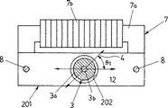
この時計用の2極式ステップモータ(以下単に「ステップモータ」とも云う)は、図1に示すようにロータ磁石3aとロータ軸3bとからなるロータ3と、そのロータ3を設置するためのロータ穴2を有するステータ1と、高透磁率の材料よりなる磁芯7aに導線7bが巻回され、磁芯7aの両端がステータ1の両端と磁気的に接続された励磁用のコイル7を備えている。
そして、このステップモータは、図22で説明した従来の時計用の2極式ステップモータと、ステータ1の構造以外は同じであるため、それらの同じ部分に関しては図22と同一の符号を付してあり、それらの説明は省略する。
【0037】
このステップモータのステータ1は、図2に示すようにそれぞれ高透磁率の材料よりなる第1のステータ部品1a(以下単に「ステータ部品1a」と云う)と第2のステータ部品1b(以下単に「ステータ部品1b」と云う)とが、低透磁率もしくは非磁性の材料よりなる連結部1c,1dを介して結合して構成されている。
【0038】
そして、そのステータ1のほぼ中央に形成されているロータ穴2の内周に、図1に示したようにロータ3を回転方向の所定の位置、すなわちロータ磁石3aの直径方向に2極に着磁された磁極を結ぶ線4が、ステップモータの非駆動時に初期位相角θ1 になる位置で、ロータ磁石3aの磁極とステータ1との磁気作用により所定の保持トルクで回転しないように保持する複数の保持トルク設定手段を設けている。
その複数の保持トルク設定手段は、この実施の形態では、図2に明示するように、ロータ穴2の内周に形成した一対の凹部5a,5bと一対の連結部1c,1dであり、その凹部5a,5bと連結部1c,1dはロータ穴2の中心に対して対称な位置に形成されている。
【0039】
そして、図示のようにその一対の凹部5a,5bと一対の連結部1c,1dの設置角度は異なる。その設置角度はステータ1の励磁方向の磁界方向線12に直角方向に対する配置角度をいうが、その詳細は第2の実施形態以降(図6以降)で説明する。
また、ステータ1の長手方向の両端部には、それぞれコイル7の磁芯7aの両端と磁気的に接続するための固定用の穴6,6を形成している。
【0040】
このステータ1を製造するには、高透磁率の材料であるパーマロイよりなる厚さ500μmの帯材から、プレス加工により、後のプレス加工のための位置決め用の穴となるパイロット穴とロータ穴2の下穴と固定用の穴6,6とを形成すると共に、一部上記帯材と連結するつなぎ部分(図示せず)を残した外形形状を打ち抜く。
次に、連結部1c,1dとなる部分に幅200μmのスリットを打ち抜きで形成し、そのスリットに低透磁率の材料もしくは非磁性の材料よりなる所定の長さの線材を挿入し、レーザー溶接で突き合わせ溶接を行ってスリットにより分離していたステータ部品1aとステータ部品1bとを結合する。
【0041】
その後、ロータ穴2と凹部5a,5bの部分をプレス加工で打ち抜き、最後に帯材と連結する上記つなぎ部分を打ち抜いて外形加工を終了する。そして、その外形加工が終了したものを磁気焼鈍を行って、ステップモータのステータ1とする。
【0042】
次に、このような構造のステータ1を組み込んでステップモータを構成したときに、低消費電力化を達成するために必要な適正条件を求めるために行った実験結果について説明する。
実験では、ステップモータの保持トルクと消費電力との関係、及び初期位相角と消費電力との関係、さらには消費電力とステータの連結部の構造との関係についてそれぞれ調べた。
【0043】
なお、実験は既存の時計用の2極式ステップモータに、この実施の形態によるステータ1を組み込んだもので測定を行った。また、駆動波形としてはチョッパ駆動波形を用い、駆動波形の各パルスのON/OFF比を調節して正常な駆動ができる最小消費電力を求めた。
特に、測定に用いたステータ1に関しては、凹部5a,5bの部分をプレス加工で形成せずに、各測定の条件に合わせて、磁気焼鈍前に放電加工により形成するようにした。
【0044】
まず最初に、保持トルクと消費電力の関係について説明する。
時計用ステップモータにおける消費電力は、保持トルクを減少させることにより励磁に必要なコイル7に流す電流を減少させることができるので、その結果として低消費電力化が図れるものと考えられる。
そこで、実際に保持トルクを変化させた場合の消費電力の変化について、実験を行って調べた。
【0045】
その測定に使用したステータ1は、保持トルクを調整するためにロータ穴2の内周に設ける半円形の凹部5a,5bの切り込み深さを変えたものを数種類用意した。また、自作のロータ回転角測定器によりロータ3の変位角度に対する角速度を測定し、その測定結果とロータ3のイナーシャより運動方程式を解いて各ステータ1について保持トルクを算出した。
また、消費電力は、1ステップ駆動するときのコイル7に流れる電流と印加した駆動電圧の積を積分して求めた。さらに、保持トルクの大きさは変位角度依存性があるので、各測定値の比較においては最大保持トルクを用いた。そして、測定に用いたステータ1の最大保持トルクは、概略50nNm刻みで50nNmから250nNmまでのものを作った。
【0046】
その実験による測定結果を図3に示す。その測定結果によれば、最大保持トルクが250nNmのときに消費電力が約800nJであったものが、最大保持トルクを100nNmにまで低下させたときには、消費電力は約350nJとなり、設定した最大保持トルクと1ステップ駆動するのに要する消費電力の関係は、概略比例関係にあることがわかった。
このように、保持トルクを半減させると消費電力も半減することから、保持トルクの低減は消費電力の低減に大きな効果があることがわかった。
【0047】
ところで、前述したように、時計用ステップモータでは、時計を落下させた際に衝撃により針飛びを起こさないようにしたり、正確な時間の表示ができるようにしたり、軸受けや歯車で発生する摩擦トルクに抗して指針を静止位置に安定して停止させることができるようにするために、必要最小限の保持トルクが必要である。
そして、ロータの持つ保持トルクにより形成される保持ポテンシャルに対して、衝撃により受け取る時計の指針の運動エネルギーが小さければ、針飛びは起こさない。つまり、指針のモーメントを小さく調整することで、保持ポテンシャルを小さく、すなわち保持トルクを小さくすることができる。
【0048】
このように、指針のモーメントを小さく調整することにより、必要最小限の保持トルクを、通常の時計用ステップモータの保持トルクに対して数分の1程度の極端に小さな保持トルクにすることが可能となる。
このように、図3に示した測定結果から、保持トルクの低減が消費電力の低減に関して効果的であり、その保持トルクは通常の時計用ステップモータの保持トルクの数分の1にまで極端に小さくすることが可能であることがわかった。
【0049】
次に、初期位相角と消費電力との関係について説明する。
図1に示した初期位相角θ1 は、回転トルクと保持トルクの位相差を示すものであり、ロータ穴2の内部に発生する磁界の方向となる磁界方向線12と、ロータ3の静止位置でのロータ磁石3aの磁化の方向の線4とのなす角度であり、ステップモータの駆動における重要なパラメータである。
【0050】
実験では、初期位相角と消費電力との関係を調べるために、ロータ穴2の内周に設けた2つの凹部5a,5bの設置位置を変えることにより、最大保持トルクを150nNmに一定に設定して、初期位相角だけを変えるようにした数種類のステータ1を使用した。
また、初期位相角は、自作のロータ回転角測定器によりロータ3の変位角度に対する角速度を測定すると同時に、ロータ3が回転運動をすることによりコイル7に発生する逆起電流を測定して算出した。
【0051】
消費電力は、1ステップ駆動するときのコイル7に流れる電流と印加した駆動電圧の積を積分して求めた。なお、測定に用いたステータ1の初期位相角は、概略10度刻みで20度から80度までのものを作成した。
その実験による測定結果を図4に示す。その測定結果によれば、初期位相角が20度から40度までの範囲では消費電力が急激に低下し、50〜60度で最小となり、それ以降は初期位相角を大きくしていくと消費電力は緩やかに増加した。
【0052】
一般的には、初期位相角の最適値としては45度が用いられるが、この実験のように最大保持トルクを150nNmのように小さくしたときには、消費電力が最も小さくなる初期位相角の最適値は45度よりも大きい角度側に移動することがわかった。 以上の結果より、時計用ステップモータの低消費電力化には、最適な初期位相角の設定が必要であることがわかった。そして、最大保持トルクを150nNmのように小さくした場合には、最適な初期位相角度は45度よりも大きな角度となり、その角度は今回の測定結果では50〜60度になることがわかった。
【0053】
次に、消費電力とステータの連結部の構造との関係について説明する。
図2に示したステータ1のように、ステータ部品1aとステータ部品1bとを、低透磁率もしくは非磁性の材料からなる連結部1c及び1dで結合した構造の場合には、ステータ1をステータ部品1aとステータ部品1bとの2つの部分に磁気的に分離することができるため、ロータ3を回転させるための磁界をロータ穴2の内部に効率的に発生させることができる。
【0054】
そこで、今回この連結部と消費電力との関係を調べるために実験を行なった。 その実験では、図2で説明したステータ1と、図25に示す従来の時計用ステップモータに使用されている1対の凹部5a,5bを有するステータ221を使用した場合とで比較した。
その従来のステータ221は、高透磁率の材料よりなる連絡部223a,223bの各最小幅Bを100μmと200μmにしたものを2種類用意した。
一方、図2で説明した構成のステータ1は、連結部1c,1dのステータ端縁までの幅Waをそれぞれ300μmとし、ステータ部品1aとステータ部品1bの間隔Wbをそれぞれ200μmとした。
【0055】
また、比較するステータ1とステータ221は、共に同じ保持トルクと初期位相角になるようにした。
実験の結果は、従来のステータ221を用いたものでは、連絡部223a,223bの最小幅Bを200μmとしたものでは、用いた駆動波形ではロータ穴222の内部に十分な磁界の発生ができないためにロータを回転させることができなかった。
【0056】
一方、連絡部223a,223bの最小幅Bを100μmにすることにより磁気的飽和を起こし易くしたステータ221を用いたものでは、ロータを回転させることができた。
その時の消費電力を、ステータ1を使用した場合の消費電力と比較した結果、ステータ1を用いたものでは、ステータ221を用いたものに比べて約20%の消費電力を低減することができた。
また、ステータ1は、連結部1c,1dが低透磁率の材料もしくは非磁性の材料で形成されているので、連結部を極端に細くする必要がないため十分な機械的強度を確保することができた。
この結果から、ステータ1は、連結部1c,1dを低透磁率の材料、もしくは非磁性の材料にすることが低消費電力化の点で好ましいことがわかった。
【0057】
以上、時計用ステップモータの保持トルクと消費電力との関係、及び初期位相角と消費電力との関係、さらには消費電力と連結部の構造との関係についてそれぞれ調べた結果から、時計用ステップモータの低消費電力を実現するために必要なステータの条件としては、次の3つがあることがわかった。
すなわち、1つ目は必要最小限の小さな保持トルクにすること。2つ目は最適な初期位相角の設定を保持トルクとは別に独立して行えるようにすること。3つ目は磁気的にステータを左右2つの部分に分離できる構造にすること。
【0058】
したがって、この3つ全ての条件を同時に満足するステータを使用すれば、目的とする時計用ステップモータの低消費電力化が図れる。
すなわち、具体的には図2に示したように、保持トルクと初期位相角θ1 とを独立して設定できるようにするために、ロータ穴2の内周に複数の凹部5a,5bを設け、2つに分けたステータ部品1aとステータ部品1bとを低透磁率の材料もしくは非磁性の材料からなる連結部1c,1dで結合する構造のステータ1にすることが最も好ましい。
そのような構造にステータ1をすれば、保持トルクは凹部5a,5bの大きさにより、また初期位相角は凹部5a,5bの設置位置を変えることにより調節できるため、低消費電力化に適した保持トルクと初期位相角を独立して設定することができる。
【0059】
次に、以上の内容を実施したステップモータを実際に作成し、そのステップモータの消費電力を測定して、低消費電力化に関する効果を調べた結果について説明する。
実験では、既存の時計用の2極式ステップモータに、既存のステータに代えてこの実施の形態によるステータ1を組み込んで、消費電力の測定を行った。
その際に使用したステータ1は、材料に厚さ500μmのパーマロイを使用し、連結部1c,1dにはニクロムを使用した。また、連結部1c,1dの寸法は、図2に示した幅Waを300μm、ステータ部品1aとステータ部品1bとの間隔Wbを200μmとした。
【0060】
さらに、そのステータ1に設けるロータ穴2の直径は1300μmとし、そのロータ穴2の内周に設置する凹部5a,5bの大きさと設置位置を調節して初期位相角を60度とし、保持ポテンシャルを100nNmに設定した。また、ロータ磁石3aとしては、外径800μm厚み400μmのサマリウムコバルト磁石を用いた。
このようなステータ1を組み込んだ時計用ステップモータについて消費電力を測定したところ、1ステップ当たり約300nJの消費電力を達成することができた。
この結果、図25で説明した従来のステータ221を使用した場合に比べて消費電力を約20%低減することができた。
【0061】
〔第2の実施形態:図5乃至図10〕
次に、この発明による時計用の2極式ステップモータの第2の実施形態を図5乃至図10を参照して説明する。
図5はこの発明による時計用の2極式ステップモータの第2の実施形態を示す図1と同様な平面図、図6は同じくその時計用の2極式ステップモータにおけるステータの構造を示す平面図、図7は同じくそのステータに設けられている保持トルク設定手段である凹部を拡大して示す平面図である。
【0062】
この第2の実施形態の時計用の2極式ステップモータは、図1乃至図4で説明した第1の実施形態の時計用の2極式ステップモータとステータの構造以外は同じであるため、それら同一の部分については説明を省略する。
この図5に示す第2の実施形態の時計用の2極式ステップモータは、ステータ11の形状が図6に示すような形状をしており、ロータ穴2の内周にその周方向に異なる設置角度で複数の保持トルク設定手段である2対の凹部15c,15dと、15e,15fをそれぞれ形成している。
【0063】
そして、その対の凹部15c,15dと対の凹部15e,15fは、それぞれロータ穴2の中心に対して対称な位置にそれぞれ形成されている。
そのステータ11は、高透磁率の材料で形成されていて、対の凹部15c,15dと対の凹部15e,15fは、共に保持トルクと初期位相角θ1 を設定するためのものであり、その対の凹部15c,15dの中心を通る直線25と、ロータ穴2の中心を通りステータ1の励磁方向の磁界方向線12と直角な直線27とがなす角度を、凹部15c,15dの設置角度θ2 としている。
【0064】
また、一対の凹部15e、15fの中心を通る直線(図6では磁界方向線12に一致する)と直線27とがなす角度を、凹部15e、15fの設置角度θ3 としている。なお、その設置角度θ2 とθ3 は、図6で反時計回り方向を正の値とする。
また、2つの保持トルク設定手段の配置角度が、ロータ穴2の周方向に180度異なる場合には、それらを同一の設置角度とみなす。その理由は、2極式ステップモータの設置角度の位相差が180度の場合は電気的位相差はその2倍の360度になり、その2つの保持トルク設定手段には同じ向きのトルクが働くためである。
【0065】
各凹部15c〜15fは、全て同じ大きさで同じ形状をしており、その凹部15fを図7に拡大して示すように、ロータ穴2の内径と、ロータ穴2と同心円の円弧16とで挾まれた部分を切り欠いたほぼ矩形の形状をしていて、その切り欠き部分の幅をそれぞれ幅Wcとしている。そして、その各凹部15c〜15fの深さDは、ロータ穴2の半径R1 と円弧16の半径R2 との差である。
【0066】
そのステータ11を製造する際には、高透磁率の材料であるパーマロイよりなる厚さ500μmの帯材から、プレス加工により、プレス加工における位置決め穴となるパイロット下穴とロータ穴2の下穴と固定用の穴6,6とを形成すると共に、一部上記帯材と連結するつなぎ部分(図示せず)を残した外形形状を打ち抜く。
次に、ロータ穴2と凹部15c,15d及び凹部15e,15fの部分をプレス加工で打ち抜き、最後に帯材と連結する上記つなぎ部分を打ち抜いて外形加工を終了する。そして、その外形加工が終了したものを磁気焼鈍を行って、ステップモータのステータ11とする。
【0067】
次に、このような構造のステータ11を使用するステップモータにおいて、2対の凹部15c,15dと凹部15e,15fの設置角度θ2 とθ3 をそれぞれ変化させたときの初期位相角θ1 と保持トルクとの関係を調べるために行った実験結果について説明する。
その実験は、国際公開WO 98/30869 号公報に開示されている回転情報測定装置を用いて行い、保持トルクの測定は直接測定したロータの変位角に対するロータの角速度変化から、運動方程式を解くことによって保持トルクを求めた。
【0068】
また、初期位相角θ1 は、直接測定したロータの変位角と、そのロータの変位角に対するロータの角速度変化と同時に測定した逆起電力より求めた。
そして、測定に使用したステップモータは、既存の時計用ステップモータのステータを、図6で説明したステータ11に組み代えたものを使用し、それで初期位相角θ1 と保持トルクの測定をそれぞれ行った。
【0069】
また、測定に使用したステップモータのステータ11は、凹部15c,15d及び凹部15e,15fの形成にプレス工程を行わず、磁気焼鈍前に各設置角度θ2 ,θ3 となる位置に、1対の凹部15c,15d及び1対の凹部15e,15fをそれぞれ放電加工により形成した。
そして、その1対の凹部15c,15dの設置角度θ2 を15度とし、もう1対の凹部15e、15fの設置角度θ3 を45度から90度まで15度刻みに変化させたステータ11を複数作成し、それらの各ステータ11を組み込んだステップモータについて初期位相角θ1 と保持トルクの測定をそれぞれ行った。
なお、その各ステータ11の各凹部15c〜15fは、全て凹部の幅Wcを400μm、深さDを150μmに作成した。
【0070】
測定は、従来の構造の時計用ステップモータと比較するため、図24に示したように1対の凹部205a,205bの各幅Wcを400μm、深さDを150μmとし、設置角度θ12を30度から75度まで15度刻みに変えたステータ211を複数作成し、それらの各ステータ211を組み込んだステップモータについて初期位相角θ1(図22参照)と保持トルクの測定を行った。
その測定結果によれば、従来の構造のステータ211を組み込んだステップモータでは、初期位相角θ1 は設置角度θ12と測定誤差範囲内で一致した。また、最大保持トルクは約250nNmで設置角度θ12に依存せず一定となった。
【0071】
この測定結果より、従来のステータ211を使用した構造のステップモータでは、初期位相角θ1 は設置角度θ12により決定され、最大保持トルクは設置角度θ12には依存しないということがわかった。
次に、一対の凹部の寸法と最大保持トルクの関係を調べるために行った実験結果について説明する。
【0072】
実験には、図24に示したように、1対の凹部205a,205bを形成したステータ211を使用し、その各凹部205a,205bの幅Wcをそれぞれ400μmで一定とし、その凹部205a,205bの深さDを50、100、150、200μmとそれぞれ異ならせて複数のステータ211を用意した。
また、逆に各凹部205a,205bの深さDを150μmで一定とし、今度は凹部の幅Wcを100、200、300、400μmとそれぞれ異ならせた複数のステータ211も作成した。
【0073】
そして、これらのステータ211を組み込んだステップモータについ、順次保持トルクの測定を行った。
その測定結果を図9及び図10に示す。
最大保持トルクは、図9に示すように凹部の深さDを増すにしたがって急激に増加し、100μm以降では緩やかな増加になることがわかった。また、その最大保持トルクは、図10に示すように凹部の幅Wcを増すにしたがって直線的に増加し、凹部の幅Wcにほぼ比例することがわかった。
【0074】
この実験結果により、最大保持トルクは文献等に記載されているように凹部の面積和に比例しないことがわかる。つまり、今回の試験に使用したステータ211は、一対の凹部205a,205bを設けていて、その凹部205aと205bの面積和は、その一方の凹部の幅Wcと深さDの積のほぼ2倍になる。
そのため、図9に示した測定に使用したステータ211は、凹部の幅Wcを400μmに一定にしているため、最大保持トルクが凹部の面積和に比例するものとすれば、その最大保持トルクは凹部の深さDに比例していなければならない。
【0075】
ところが、図9に示した測定結果は、最大保持トルクと凹部の深さDの関係は比例関係を示す直線にはなっていない。この測定結果より、最大保持トルクは凹部の面積和に比例せず、凹部の深さDが100μm以下の領域においてその深さDを変えることにより設定することができ、深さDが100μm以上を超えるとほぼ一定となることを示している。
また、最大保持トルクを小さくする方向に調節する際に、その調節を凹部の深さDを変えることによって行おうとすると、図9から明らかなように凹部の深さDが100μm以下の領域では、特に50μm以下の部分で凹部の深さDの変化に対する最大保持トルクの変化が大きいので、加工精度を考えるとその50μm以下の領域での調整は、安定した最大保持トルクを設定する点で難しいので避けた方がよい。
【0076】
これに対し、図10に凹部の深さDを150μmにした場合の測定結果を示したように、最大保持トルクは凹部の深さDを150μm程度以上にすれば、その凹部の幅Wcにほぼ比例するので、最大保持トルクの調節には凹部の幅Wcを変えるのが適していることがわかる。
このように、最大保持トルクは、図24で説明した設置角度θ12には依存しないが、一対の凹部205a,205bの各幅Wcと深さDにより決定されることがわかる。
【0077】
一方、図6で説明したステータ11を組み込んだステップモータの測定結果は、図8に示すように、従来のステータ211を組み込んだステップモータと異なる結果になった。
すなわち、初期位相角θ1 は、対の凹部15c,15dの設置角度θ2 と、対の凹部15e,15fの設置角度θ3 のいずれにも一致しなかった。
また、最大保持トルクは、それぞれ対の凹部15c,15dと凹部15e,15fから得られる最大保持トルク250nNmの2倍の合計値500nNmで一定とはならず、対の凹部15e,15fの設置角度θ3 の増加に伴って、今回測定した範囲で430nNmから130nNmへと減少した。
【0078】
以上、従来のステータ211と図6で説明したステータ11を組付けたステップモータの測定結果を比較すると、設定される初期位相角と保持トルクは、複数の保持トルク設定手段である各凹部15c〜15eを形成したステータ11を使用したものでは、従来のステータ211を使用したものに比べて全く違う現象が起きることがわかった。
これらの測定結果を更に比較検討した結果、複数の保持トルク設定手段である2対の凹部15c,15dと凹部15e,15fを設けたステータ11を使用したステップモータでは、初期位相角θ1 と最大保持トルクは、個々の保持トルク設定手段、すなわち対の凹部15c,15dと対の凹部15e,15fが、各々単独でロータ穴2の内周に設けられた時に得られる各最大保持トルク及び初期位相角θ1 の各々のベクトルの合成になることがわかった。
【0079】
また、この第2の実施の形態における時計用ステップモータは、1ステップあたりの変位角度が360度ではなく180度の2極式ステップモータであるため、そのステップモータの電気角は実際の角度の2倍となる。
そのため、個々の保持トルク設定手段に対応する各々のベクトルとしては、各々の保持トルク設定手段が単独にロータ穴2の内周に設けられた時に形成する最大保持トルクと初期位相角θ1 の2倍で与えられる。
【0080】
さらに、従来のステータ211を使用したステップモータの測定結果より、各々の初期位相角θ1 の代わりに、各々の保持トルク設定手段である2対の凹部15c,15dと凹部15e,15fの設置角度θ2 ,θ3 を用いて構わない。
このように、複数の保持トルク設定手段を有するステータ11を使用したステップモータにおいては、上記のようにして得られる各々のベクトルをベクトル合成することにより、初期位相角θ1 と最大保持トルクをそれぞれ設定することができる。そして、そのベクトル合成により設定される初期位相角θ1 と最大保持トルクは、今回行った実験の測定結果とよく一致した。
【0081】
つまり、2つの保持トルク設定手段、すなわち対の凹部15c,15dと凹部15e,15fをそれぞれ単独で設けた場合には、それら保持トルク設定手段はおのおの250nNmの最大保持トルクを形成するときであっても、対の凹部15c,15dの設置角度θ2 が15度であって、対の凹部15e,15fの設置角度θ3 が90度で、その設置角度θ2 とθ3 とが75度ずれている場合には、図8に示した測定結果から最大保持トルクは約130nNm、初期位相角θ1 は約53度になる。
【0082】
このように、この第2の実施の形態における2対の凹部15c,15d及び凹部15e,15fを設けたステータ11を使用するステップモータによれば、保持トルク設定手段が各凹部15c〜15fの幅Wcと深さDにより独立して設定することができる最大保持トルクと、その凹部15c〜15fを設ける位置となる設置角度θ2 ,θ3 を調節することにより、広い範囲の保持トルクと初期位相角θ1 の設定を行うことができる。
【0083】
それにより、2対の凹部15c,15dと凹部15e,15fのそれぞれ設置角度θ2 ,θ3 を調節し、それらの設置角度の差を大きく、言い換えると各保持トルクの位相角の差を大きく取ることにより、それぞれ対をなす凹部15c,15dと凹部15e,15fを単独で設けた場合に形成される各々の保持トルクは大きいままでも、ステップモータ全体での保持トルクは各々の保持トルクをベクトル合成したものになるため、結果として得られる保持トルクを極端に小さな値にすることができる。
【0084】
次に、2対の凹部を設けたステータと、1対の凹部を設けたステータをそれぞれ組み込んだ時計用ステップモータについて消費電力を確認する実験を行って比較した結果について説明する。
2対の凹部を設けたステータと、1対の凹部を設けたステータは、共に初期位相角を約55度に、保持トルクの最大値が約75nNmになるように形成した。また、ステータの材料には、厚さ500μmのパーマロイを用い、そのステータに設けるロータ穴の直径は1700μmとし、ロータ磁石としては外径1000μmで厚み400μmのサマリウムコバルト磁石を用いた。
【0085】
まず、図6に示した2対の凹部15c,15dと15e,15fを設けるステータ11として、各凹部15c〜15fの幅Wc(図7)を400μm、深さDを150μmとし、一対の凹部15c,15dの設置角度θ2 を15度とし、もう1対の凹部15e,15fの設置角度θ3 を96度に設置することにより、初期位相角θ1 が55度で、最大保持トルクが75nNmのステップモータが実現できた。
これに対して、図24に示した従来の1対の凹部205a,205bを設けたステータ211の構造のものは、各凹部205a,205bの幅Wcを120μm、深さDを150μmとして設置角度θ12を55度に設置する必要があることがわかった。
【0086】
そして、その2種類のステータ11と211を各々組み込んだステップモータについて、実駆動での消費電力を測定したところ、最大保持トルクとして約250nNmを持つ通常の時計用ステップモータでは1ステップ当たり800〜900nJの消費電力を示すのに対し、上記2種類のステータ11と211を各々組み込んだステップモータでは、共に1ステップ当たり約400nJの消費電力を示し低消費電力化が計れた。
そして、それら2種類のステータ11と211を各々組み込んだステップモータでは、特性上の差がみられなかった。
【0087】
以上の実験結果より、2対の凹部を設けたステータと、1対の凹部を設けたステータを各々組み込んだステップモータで、同じ特性を得るのに2対の凹部15c,15dと凹部15e,15fを設けたステータ11を組み込んだステップモータでは、各凹部15c〜15fの幅Wcを400μmとし、深さDを150μmにすることで得られた。
これに対し、従来からある1対の凹部205a,205bを設けたステータ211を組み込んだステップモータでは、各凹部205a,205bの幅Wcを120μmにし、深さDを150μmにすることで、2対の凹部を設けたステータを組み込んだステップモータと同じ特性が得られた。
【0088】
したがって、各凹部205a,205bの幅Wcを、2対の凹部を設けるステータ11に比べてかなり小さくしなければならない。
そのため、このように1対の凹部205a,205bを設けるステータ211では、加工上及び生産性の面で問題が生じる。
すなわち、今回の実験に使用した2種類のステータ11,211は、共に高い精度の試験結果が得られるようにするため、各凹部を高い精度で加工することができる放電加工により形成したので、凹部の幅120μmの加工に関して加工上の問題は生じなかった。
【0089】
しかしながら、ステータは、実際に工場で生産する場合には生産性の点を考慮してプレス加工で製造する必要がある。ところが、プレス加工では厚み500μmのパーマロイの帯材に幅120μmで深さ150μmの凹部を精度良く加工することは非常に難しく、それを可能にしたとしても用いる金型の寿命は非常に短いものになってしまうため、生産性が非常に悪くなってしまう。
そうかといって、加工精度の高い放電加工でステータを製造すれば、加工に時間がかかるため、非常に高価なものになってしまう。
【0090】
これに対し、図6で説明した2対の凹部15c,15dと15e,15fを設けるステータ11によれば、その各凹部15c〜15fの幅Wcを400μmに、深さDを150μmのままで、対の凹部15c,15dの設置角度θ2 を13度に、対の凹部15e,15fの設置角度θ3 を97度にそれぞれ調整することにより、初期位相角θ1 を55度にして、最大保持トルクを50nNmのステップモータにすることができる。
なお、この第2の実施の形態におけるステータ11は、保持トルク設定手段としてロータ穴2の内周に2対の凹部15c,15d及び凹部15e,15fを設けた場合の例を示したが、その保持トルク設定手段として設ける凹部は、ロータ穴2の内周に3対以上設けるようにしてもよい。
【0091】
特に、ステータのロータ穴の周囲に輪列の軸穴や固定ピン用の穴が設けられている場合には、その輪列の軸穴や固定ピン用の穴と保持トルク設定手段として機能する凹部が干渉しやすいため、設定しようとする初期位相角と保持トルクを得るために、凹部を設置すべき設置角度に設置できない場合が生じることがある。
そのような場合には、上記輪列の軸穴や固定ピン用の穴と干渉する位置に対の凹部を設けた場合に形成される保持トルクを前述したようにベクトル分解し、その分解したベクトルになるように3対以上の凹部を、上記輪列の軸穴や固定ピン用の穴を避けて干渉しない位置にそれぞれ分けて配置すれは、目的とする初期位相角と保持トルクを得ることができる。
【0092】
また、主に図5及び図6を使用して説明した第2の実施の形態では、2つの保持トルク設定手段としてロータ穴2の内周に2対の同寸法のほぼ矩形の形状をした凹部15c,15d及び15e,15fを設けた場合の例を示したが、その2対以上設ける各凹部は、ロータ穴2に対して開口部を持つ形状であればどのような形状のものであってもよいし、その対をなす凹部同士の形状及び寸法が同じであれば、対ごとに形状及び寸法を変えてもよい。
【0093】
〔第3の実施形態:図11及び図12〕
次に、この発明による時計用の2極式ステップモータの第3の実施形態を図11及び図12を参照して説明する。
図11はこの発明による時計用の2極式ステップモータの第3の実施形態を示す図1と同様な平面図、図12は同じくその時計用の2極式ステップモータにおけるステータの構造を示す平面図である。
この第3の実施形態の時計用の2極式ステップモータは、図1乃至図4を参照して説明した第1の実施形態の時計用の2極式ステップモータとステータの構造以外は同じであるため、それら同一の部分については説明を省略する。
【0094】
図11に示す第3の実施形態の時計用の2極式ステップモータは、ステータ31の連結部31c,31dが、複数の保持トルク設定手段の少なくとも1つをなしている点に関しては、図1で説明したステータ1に連結部1c,1dを有しているステップモータと同じであり、そのステップモータとはステータ31のロータ穴2の内周の連結部31c,31dと異なる位置に、保持トルク設定手段として機能するほぼ矩形形状の切欠きからなる1対の凹部35a,35bを形成した点が異なる。
そして、その凹部35aと35bは、ロータ穴2の中心に対して対称の位置に形成されている。
【0095】
なお、図11では連結部31c,31dの設置角度を0度とした場合の例を示したが、その設置角度は0度でなくてもよい。
このステータ31の製造方法は、図2で説明したステータ1と同様であり、高透磁率の材料であるパーマロイよりなる厚さ500μmの帯材をプレス加工し、パイロット穴とロータ穴2の下穴と固定用の穴6,6と共に、一部上記帯材と連結するつなぎ部分(図示せず)を残した外形形状の打ち抜きを行う。
【0096】
その後、連結部31c、31dとなる部分にスリットを形成し、そのスリットに低透磁率の材料もしくは非磁性の材料の線材を挿入し、レーザー溶接により第1のステータ部品31aと第2のステータ部品31bとを上記線材を介して結合する。
次に、ロータ穴2と凹部35aと35bの部分をプレス加工で打ち抜き、最後に帯材と連結する上記つなぎ部分を打ち抜いて外形加工を終了する。そして、その外形加工が終了したものを磁気焼鈍を行って、ステップモータのステータ31とする。
【0097】
このような構造のステータ31は、連結部31c,31dの部分が高透磁率の材料をプレス加工で切り欠いた部分に低透磁率の材料もしくは非磁性の材料を溶接で結合したものであるので、その部分が1対の凹部35aと35bと同様に保持トルク設定手段として機能してロータ3を所定の位置に保持する働きをする。 そして、そのステータ31を組み込んだステップモータを確認した結果、連結部31c,31dにより形成された保持トルクの初期位相角は、1対の凹部35aと35bと同様に連結部31c,31dの設置角度にほぼ一致し、形成された保持トルクの大きさは、同一寸法の凹部が形成する保持トルクとほぼ一致する大きさになることがわかった。
【0098】
以上の点から、このステータ31の構造にしても、図1乃至図4で説明したステップモータと同様に、連結部31c,31dを単独でロータ穴2の内周に設けた場合に形成される保持トルクと、そのロータ穴2の内周に1対の凹部35a,35bを単独で設けた場合に形成される各保持トルクのベクトルを合成した保持トルクが、最終的にステップモータの設定保持トルクになるはずである。
【0099】
そこで、それを確認するために行った実験について、以下説明する。
この実験に使用するステータ31としては、図12に示すようにロータ穴2の内周に1対の連結部31c,31dと、1対の凹部35a,35bをそれぞれ形成したものを使用する。
そして、その一対の凹部35a,35bの図12に示す設置角度θ4 と、凹部35a,35bのそれぞれの幅Wcを、初期位相角θ1 (図11)が約55度になり、最大保持トルクが約75nNmになる位置に調整した。
【0100】
また、ステータ31の材料としては、厚さ500μmのパーマロイを使用し、ロータ穴2の直径は1700μmとした。さらに、ロータ磁石3としては、外径1000μmで厚み400μmのサマリウムコバルト磁石を使用した。
このように形成したステータ31を、時計用ステップモータに組み込んで初期位相角θ1 と保持トルクの測定を行った結果、1対の凹部35a,35bの凹部の幅Wcを270μmにすると共に深さD(図7を参照)を150μmにし、1対の凹部35a,35bの設置角度θ4 を78度に設置することにより、初期位相角θ1 が約55度で、最大保持トルクが約75nNmのステップモータを実現することができた。
【0101】
この実験結果は、ステップモータの保持トルクの設定は、連結部31c,31dにより形成された保持トルクと、ロータ穴2の内周に設けた1対の凹部35a,35bにより形成された保持トルクのベクトルをそれぞれ合成したもので設定されることを示している。
このように、この実施の形態のステータ31を使用すれば、初期位相角θ1 が約55度で、最大保持トルクが約75nNmのステップモータを実現するのに、1対の凹部35a,35bの各幅Wcは270μmにすればよいので、図24を使用して説明した従来のステータ211における凹部の幅Wcを120μmとするものに比べて遥かに大きな凹部の幅にすることができる。したがって、ステータ31の加工が容易になる。
【0102】
さらに、このステータ31を使用すれば、連結部31c,31dの幅Wbを広くすることにより、一対の凹部35a,35bの凹部の幅Wcを広くすることができる利点がある。
例えば、上述したステータ31では、連結部31c,31dの幅Wbは200μmのものを使用したが、その幅Wbを400μmと広くすれば、初期位相角θ1 を約55度、最大保持トルク約75nNmに設定するために必要な一対の凹部35a,35bの大きさは、凹部の幅Wcが450μmで、深さDを150μmにして、設置角度θ4 を83度にすればよい。
【0103】
つまり、同じ初期位相角θ1 と保持トルクを設定する場合に、連結部の幅Wbを200μmから400μmに広くすれば、凹部35a,35bの幅Wcを270μmから450μmに広げることができる。
そして、そのステータ31の連結部31c,31dの幅Wbを400μmとし、一対の凹部35a,35bの設置角度θ4 を85度にすると共に、凹部の幅Wcを430μmにすれば、前述した第2の実施の形態と同様に、初期位相角θ1 を55度に、最大保持トルクを50nNmに設定することができる。
【0104】
次に、このステータ31を組み込んだ時計用ステップモータを実駆動させたときの1ステップ当たりの消費電力を測定した結果について説明する。
そのステータ31を組み込んだステップモータの1ステップ当たりの消費電力の測定結果は、約350nJであった。この値は、最大保持トルクが約250nNmの通常の時計用ステップモータにおける1ステップ当たりの消費電力800〜900nJに比べて、かなり小さな消費電力である。
【0105】
そして、この実施の形態におけるステップモータの1ステップ当たりの消費電力約350nJは、同一の保持トルクを持つように設定した場合の前述した第2の実施の形態におけるステータ11を使用した時計用ステップモータの消費電力約400nJに比べて、50nJの低消費電力化が図れている。
その理由としては、ステータ31の構造において、非磁性の連結部31c,31dの働きによるものであると考えられる。
【0106】
以上述べたように、この第3の実施の形態におけるステータ31を使用すれば、第2の実施の形態で説明したステータ11と同様に、生産性を損なうことなく低消費電力化に適した極端に小さな保持トルクを設定することができる。
また、図11及び図12では、保持トルク設定手段として連結部31c,31d以外にロータ穴2の内周に1対の凹部35a,35bを設けた場合の例について説明したが、そのロータ穴2の内周に設ける凹部は2対以上設けるようにしてもよい。
【0107】
また、この第3の実施の形態において、ロータ穴2の内周に設ける凹部35a,35bの形状は、図12に示したような1対の同寸法のほぼ矩形のものに限るものではなく、ロータ穴2に対し開口部を持つ形状のものであれば、どのような形状のものであっても互いに対をなす凹部同士の形状で寸法が同じものであれば構わない。
【0108】
〔第4の実施形態:図13〕
次に、この発明による時計用の2極式ステップモータの第4の実施形態を図13を参照して説明する。
図13はこの発明による時計用の2極式ステップモータの第4の実施形態におけるステータの構造を示す図6と同様な平面図である。
この第4の実施形態の時計用の2極式ステップモータは、図5乃至図6を参照して説明した第2の実施形態の時計用の2極式ステップモータとステータの構造以外は同じであるため、それら同一の部分については説明を省略する。
【0109】
この図13に示すステータ41は、ロータ3を回転方向の所定の位置に保持する複数の保持トルク設定手段を有しているが、その複数の保持トルク設定手段はロータ穴2の中心に関し形状が非対称のものを含んでいる。 すなわち、ステータ41に、ロータ3の保持トルクと初期位相角を決める保持トルク設定手段として、ロータ穴2の内周に1対の凹部45a,45bと、更にもう1対の凹部45c,45dを設けている。
【0110】
そして、その凹部45aと45bを、ロータ穴2の中心に関し対称な位置に配置している。同様に、凹部45cと45dも、ロータ穴2の中心に関し対称な位置に配置している。
その凹部45aと45bは、図13から明らかなように同一の形状をしているが、凹部45cと45dは同一形状ではなく、凹部45cの方が凹部45dよりも凹部の幅Wcが大きい。
【0111】
ロータ穴2の中心を通りステータ41の励磁の方向の線(図5の磁界方向線12)に直角な直線27と、一対の凹部45a,45bの中心を通る直線64とがなす角度を、凹部45a,45bの設置角度θ5 とする。同様に、一対の凹部45c,45dの中心を通る直線62が直線27となす角度を凹部45c,45dの設置角度θ6 とする。なお、設置角度θ5 ,θ6 は、共に反時計回り方向を正の値とする。
【0112】
ところで、図6で説明したステータ11では、保持トルク設定手段は2対の凹部15c,15dと15e,15fであり、そのそれぞれ対をなす凹部が形成する各保持トルクと初期位相角はそれら対の凹部毎にベクトルで表され、結果として設定される最大保持トルクはそれらのベクトルの和となった。
そして、各凹部15c〜15fは、いずれも同じ形状で同じ大きさであったので、それぞれ対の凹部ごとの二つのベクトルは大きさは同じであり、位相角はそれぞれ対の凹部ごとの設置角度θ2 ,θ3 に応じて決まるものであった。
【0113】
これに対し、この実施形態におけるステータ41も、対の凹部45a,45bと対の凹部45c,45dごとに一つの保持作用を果たすベクトルが対応し、それら2対の凹部45a,45bと45c,45dによる保持作用の合成は、やはり2つの上記ベクトルの合成となる。
【0114】
ここで、我々は1対の凹部だけを設けたステータについて、寸法が同じでない凹部を対にした場合も含めてステータを作成し、それらの各ステータについて保持トルクを調べる実験を行った。
その実験に使用したステータは、図8に示した実験データを得る際に行った実験に準じて、2つの凹部が同寸法のものについては凹部の幅Wcを共に400μmにした。さらに、凹部の寸法が異なるものについては2つの凹部の幅Wcの和が800μmになるように、幅Wcの組み合せを450μmと350μmにしたものと、500μmと300μmにしたものを製作した。
【0115】
また、凹部の深さDはいずれも150μmにした。そして、これらのステータをステップモータに組み込んで実験したところ、ロータの保持トルクおよび初期位相角は、いずれも測定誤差範囲内で一致する値を示した。
このように、凹部(凸部の場合も同様)の形状を非対称にしても、2つの凹部の幅Wcの和を一定にすれば、ロータの保持トルクおよび初期位相角を一定に保つことができるということを、実験で確認することができた。
【0116】
したがって、図13に示したステータ41の場合には、対の凹部45c,45dの各面積に大小の差があるが、凹部の深さDを一定にして幅Wcを変化させる条件で凹部の面積を変えた場合には、1対の凹部の面積和が一定であればベクトルも基本的に一定であり、凹部が非対称であること自体はベクトルに影響しない。
したがって、対をなす複数の凹部の面積和を調整することによってベクトルを調整することができ、逆にベクトルすなわち凹部の面積和を一定にして、対をなす複数の凹部の面積の割り振りを調整することもできる。
【0117】
そして、図13に示したステータ41の場合には、対の凹部45cと45dについて大きさを異ならせて面積差をつけたが、その凹部45cと45dだけでなく、対の凹部45aと45bについても大きさを異ならせて面積差をつけてもよい。
このように、対をなす凹部45cと45dの面積配分と、対の凹部45a,45bの設置角度θ5 及び対の凹部45c,45dの設置角度θ6 を選択することによって、従来のように対をなす凹部の形状が同じである構造に比べて凹部を配置する自由度が増える。したがって、ロータの保持トルクや初期位相角の設定を一層便利に行うことができる。
【0118】
〔第5の実施形態:図14〕
次に、この発明による時計用の2極式ステップモータの第5の実施形態を図14を参照して説明する。
図14はこの発明による時計用の2極式ステップモータの第5の実施形態におけるステータの構造を示す図12と同様な平面図であり、図12と対応する部分には同一の符号を付してある。
この第5の実施形態の時計用の2極式ステップモータに使用するステータ51は、図12で説明したステータ31に対して、ロータ穴2の内周に、そのロータ穴2の中心に関して対称の位置に設けた1対の凹部55aと55bの形状を、凹部55a側を凹部55b側に比べて大きくしている。
【0119】
そして、それぞれ高透磁率の材料で形成された第1と第2のステータ部品51aと51bを、低透磁率の材料あるいは非磁性の材料からなる対の連結部31c,31dを介して溶接により一体に連結し、その対の連結部31c,31dが1対の凹部55a,55bと同様の作用をして、保持トルク設定手段として機能するようにしている。
したがって、このステータ51は、実質的に2対の凹部を持っているのと同様であり、ロータ3に生じる最大保持トルクと初期位相角は、対の凹部55a,55bが形成する保持トルクに対応するベクトルと、対の連結部31c,31dが形成する保持トルクに対応するベクトルとの和になる。
【0120】
このステータ51によれば、凹部55aと55bの大きさを同じにするという制限が省かれるので、それらの配置がしやすくなる。また、凹部55a,55bを通る中心線63が、連結部31c,31dのそれぞれ中心を通る直線27となす設置角度θ7 を選択するだけで、ロータ3の保持トルクと初期位相角の設定を極めて自由に行うことができる。
【0121】
なお、図14に示したステータ51は、連結部31c,31dの中心を通る直線(この例では直線27に一致)が、ロータ穴2の中心を通りステータ51の励磁方向の直線と直角な直線27となす角度を対の連結部31c,31dの設置角度としたときに、その設置角度が0度になる場合のものを示したが、その設置角度を0度以外の角度にして、対の連結部31c,31dを傾斜させた位置に設けるようにしてもよい。
また、連結部31cの幅Wbと,連結部31dの幅Wbを異ならせるようにしてもよい。そうすれば、ステップモータの特性の設定がさらに自由になる。
【0122】
さらに我々は、上述した対の凹部(後述する凸部の場合も同様)の形状を違えた保持トルク設定手段の極限の場合として、対の凹部の一方だけを設けたもの、すなわちロータ穴の内周に凹部を1カ所だけ設けた場合の保持トルクについて調べる実験を行った。
【0123】
その実験結果によれば、凹部を1カ所だけ設けた場合も、1対の凹部により保持トルクが設定されるのと同様に保持トルクが設定された。そして、その1つの凹部に対して最大保持トルクと初期位相角を表す1個のベクトルが対応し、複数の凹部を設けた場合には、全体としてはそれら個々のベクトルの合成になることがわかった。
この実験結果からわかることは、保持トルク設定手段の基本は、それを必ずしも対の凹部にする必要はなく、対にしない単独の凹部をロータ穴の内周の所望の位置にそれぞれ配置するようにしても、所望の特性が得られることがわかった。
【0124】
ところで、ステータに設けた2つの保持トルク設定手段がロータ穴の中心に対して対称形である場合、理論的にはロータはステータから保持トルクだけを受けて軸受け部に側圧を生じないことになる。
しかしながら、対向する2つの保持トルク設定手段が、ロータ穴の中心に対して非対称になる位置にずれるにしたがってロータに側圧が生じるようになる。その側圧は、保持トルク設定手段として単独の凹部を設けた場合に最も強まり、その側圧により軸受の部分の摩擦が増大する。したがって、それに対抗するためにロータ駆動電流が若干増える傾向を示すようになるが、実際にはいくつかの保持トルク設定手段を組み合わせて配置する場合が多いので、その場合には上記側圧は相殺されるため、最終的にロータ駆動電流はあまり大きな値になることはない。
【0125】
以上、実験結果から、1カ所の凹部に対しても保持トルクと初期位相角を表す1個のベクトルが存在し、対にしない単独の凹部を複数設けた場合のベクトルは、それらのベクトルの合成になることを知った。
したがって、ステータのロータ穴の内周に保持トルク設定手段として形成する凹部は、必ずしも対にして設ける必要はない。すなわち、対にしない単独の凹部を保持トルク設定手段の基本単位にし、それをロータ穴の内周に必要な数だけ配置するようにしてもよい。
【0126】
〔第6の実施形態:図15〕
次に、この発明による時計用の2極式ステップモータの第6の実施形態を図15を参照して説明する。
図15はこの発明による時計用の2極式ステップモータの第6の実施形態におけるステータの構造を示す図13と同様な平面図であり、図13と対応する部分には同一の符号を付してある。
【0127】
この第6の実施形態の時計用の2極式ステップモータに使用するステータ61は、ロータ穴2の内周に、1対の凹部45a,45bを、それらの中心を通る直線64が直線27に対し設置角度θ5 をなす位置に設け、さらに対をなさない単独の凹部45cを、その中心を通る直線65が直線27に対し設置角度θ6 をなす位置に設けている。
【0128】
このようなステータ61によって設定される保持トルクは、1対の凹部45a、45bが形成する保持トルクに対応するベクトルと、単独の凹部45cが形成する保持トルクに対応するベクトルとの合成となる。
このように、保持トルク設定手段は、対をなす凹部の組み合わせに限るものではなく、単独の凹部を様々な位置に配置することによっても所望の特性を得ることができる。
【0129】
〔第7の実施形態:図16〕
次に、この発明による時計用の2極式ステップモータの第7の実施形態を図16を参照して説明する。
図16はこの発明による時計用の2極式ステップモータの第7の実施形態におけるステータの構造を示す図15と同様な平面図であり、図15と対応する部分には同一の符号を付してある。
【0130】
この第7の実施形態の時計用の2極式ステップモータに使用するステータ71は、ロータ穴2の内周の2カ所に凹部45cと45eを設けたものであるが、その2つの凹部45c,45eはロータ穴2の中心に対して対称な1対の凹部でなく、それぞれ対をなさない単独のものである。そして、凹部45cの中心を通る直線65が直線27に対し設置角度θ6 をなし、凹部45eの中心を通る直線64が直線27に対し設置角度θ5 をなしている。
このステータ71では、ロータ3の保持状態は、各凹部45c,45eがロータ3に対して持つ保持作用のベクトルの合成で定まる。
【0131】
〔第8の実施形態:図17〕
次に、この発明による時計用の2極式ステップモータの第8の実施形態を図17を参照して説明する。
図17はこの発明による時計用の2極式ステップモータの第8の実施形態におけるステータの構造を示す図14と同様な平面図であり、図14と対応する部分には同一の符号を付してある。
【0132】
この第8の実施形態の時計用の2極式ステップモータに使用するステータ81は、それぞれ高透磁率の材料で形成された第1と第2のステータ部品81aと81bを、幅Wbの低透磁率の材料あるいは非磁性の材料からなる対の連結部31c,31dを介して溶接により一体に連結している。
そして、ロータ穴2の内周に単独の凹部55aを設け、その中心を通る直線63が直線27に対し設置角度θ7 をなすようにしている。
【0133】
このステータ81においても、図14で説明したステータ51と同様に、対の連結部31c,31dは対の凹部と同じ作用をして保持作用のベクトルを持つ。そして、単独の凹部55aもベクトルを持つから、ロータ3の保持トルクと初期位相角はこれらのベクトルの合成で定まる。
この図17に示したステータ81も、図14のステータ51と同様に、対の連結部31c,31dのそれぞれ中心を通る直線が直線27に重なって、連結部31c,31dの設置角度は0度になっているが、ステータ51で説明した場合と同様に、その設置角度を0度でない角度にして対の連結部31c,31dを傾斜させるようにしてもよい。
また、連結部31c,31dの幅Wbを互いに異ならせるようにしてもよい。さらに、2つの連結部31c,31dの中心が、同一直線上に位置しないようにすることもできる。
【0134】
〔第9の実施形態:図18〕
次に、この発明による時計用の2極式ステップモータの第9の実施形態を図18を参照して説明する。
図18はこの発明による時計用の2極式ステップモータの第9の実施形態におけるステータの構造を示す図15と同様な平面図であり、図15と対応する部分には同一の符号を付してある。
この第9の実施形態の時計用の2極式ステップモータに使用するステータ91は、方式の異なるギャップ型とノッチ型の保持トルク設定手段を有している。
【0135】
すなわち、このステータ91には、ロータ穴92にギャップ型の保持トルク設定手段として機能するギャップ量Gの段差部94c、94dと、ノッチ型の保持トルク設定手段として機能する1対の凹部45a,45bを設けている。
このステータ91を用いたステップモータは、ロータの保持トルクと初期位相角が、1対の段差部94c、94dにより形成される保持トルクに対応するベクトルと、1対の凹部45a,45bにより形成される保持トルクに対応するベクトルとの合成で決まる。
【0136】
ところで、図23に示した従来のステータ201に見られるような単純なギャップ型ステータの場合には、ロータ穴の平均直径が約1700μmでギャップ量Gが40μmであると、ロータの最大保持トルクは約300nNmとなり、初期位相角はほぼ45度となる。
しかしながら、我々の実験結果によれば、ステップモータの効率を上げて消費電力を減らすためには、ロータの最適な初期位相角(図22のθ1 参照)は、図4を使用して説明したように、上記45度よりも大きい50度〜60度程度であるが、70度位までは実用上問題はない。
【0137】
そこで、図23における段差部204a、204bを、ステータ201の長手方向に直交する直線27上の図示している位置から反時計回り方向に例えば20度回転させた位置にすれば、初期位相角を上記の理想とする50度〜60度に近づけることができる。
しかしながら、この状態で更に消費電力の低減を図るために最大保持トルクも小さくしようとすると、ギャップ量Gを極度に小さくしなければならなくなる。したがって、そのための加工が困難になる。
【0138】
ところが、図18で説明したステータ91を使用すれば、段差部94c,94dからなるギャップ型の保持トルク設定手段と、1対の凹部45a,45bからなるノッチ型の保持トルク設定手段と備えているので、その凹部45a,45bの設置角度θ5 を適切に選択することにより、ギャップ量Gや凹部45a,45bの寸法を極端に小さくすることなしに、最大保持トルクを低減して、適切な初期位相角を得ることができる。
【0139】
ところで、図18のステータ91は、段差部94c、94dを通る直線70が、ステータ91の励磁方向に直角な直線27に重なるので、段差部94c、94dの設置角度は0度であり、1対の凹部45a,45bは、その各中心を通る直線64が直線27に対してなす角度である設置角度がθ5 になるようにしているが、その段差部94c、94dを通る直線70を直線27に対して傾斜させた位置にして段差部94c、94dを0度以外の設置角度で設けるようにしてもよい。
【0140】
なお、我々が行った実験結果によれば、段差部のギャップ量G=40μm、凹部の幅Wc=400μm、深さD=150μmのステータ91において、段差部94c、94dを通る直線70の直線27に対する設置角度=75度、凹部45a,45bの設置角度θ5 =−10度とすると、最大保持トルク=75nNm、初期位相角=55度になることを確認している。
あるいは、段差部94c、94dの設置角度を63度とし、凹部45a,45bの設置角度を−25度としたときには、最大保持トルク=50nNm、初期位相角=55度になることも確認している。
【0141】
〔第10の実施形態:図19〕
次に、この発明による時計用の2極式ステップモータの第10の実施形態を図19を参照して説明する。
図19はこの発明による時計用の2極式ステップモータの第10の実施形態におけるステータの構造を示す図17と同様な平面図であり、図17と対応する部分には同一の符号を付してある。
【0142】
この第10の実施形態の時計用の2極式ステップモータに使用するステータ101は、高透磁率の材料からなる第1,第2のステータ部品101a、101bを、幅Wbの低透磁率の材料または非磁性の材料からなる連結部31c,31bを介して一体に溶接した構造をしている。
そして、そのステータ101には、段差部94e,94fを有するギャップ型のロータ穴102を形成している。
【0143】
連結部31c,31dのそれぞれ中心を通る直線は、ステータ101の励磁方向に直角な直線27と重なっているが、段差部94e,94fを通る直線107は直線27に対し設置角度θ7 の位置に傾けて設定している。
ところで、図19の段差部94e,94fを通る直線107を、直線27に重なるようにすることによって設置角度θ7 を0度にする位置に段差部94e,94fを配設し、段差部94e,94fが低透磁率の材料または非磁性の材料で形成した連結部31c,31bに一致する位置になるようにしたステータは、すでに公知である。
【0144】
このような公知のステータの場合には、段差部だけの作用によるロータの初期位相角は前述したようにほぼ45度であり、連結部が1対の凹部と同様に作用することがこれに加わると、ベクトルの合成によって決まるロータの初期位相角(図22のθ1 を参照)は30度〜40度に減ってしまう。
低消費電力化を図る場合には、前述したように初期位相角は50度〜60度が望ましいのであり、上述したように対の段差部を対の連結部の位置に一致させて設ける従来の構成のものでは、それを達成することができなかった。
【0145】
しかしながら、図19に示したステータ101によれば、段差部94e,94fを通る直線107を、対の連結部31c,31dの中心を通る直線27に対して設置角度θ7 だけ反時計回り方向(正方向)に回転させた位置にしているので、ステップモータの低消費電力化を図る上で有効となる初期位相角50度〜70度を得ることができる。
そして、このステータ101も、対の連結部31c,31dと対の段差部94e,94fによりロータに作用するベクトルの合成によって、好ましいロータの最大保持トルクと初期位相角を得ることができる。
【0146】
〔第11の実施形態:図20〕
次に、この発明による時計用の2極式ステップモータの第11の実施形態を図20を参照して説明する。
図20はこの発明による時計用の2極式ステップモータの第11の実施形態におけるステータの構造を示す図18と同様な平面図であり、図18と対応する部分には同一の符号を付してある。
【0147】
この第11の実施形態の時計用の2極式ステップモータに使用するステータ111は、方式が別であるオーバル型とノッチ型の2種類の保持トルク設定手段を有している。
すなわち、ステータ111に、ロータ穴112を真円でなく、卵形や楕円形あるいは長円形等のオーバル形状に形成し、そのロータ穴112自体が保持トルク設定手段の一つとして機能するようにしている。
【0148】
また、そのロータ穴112の内周に、ノッチ型の保持トルク設定手段として機能する1対の凹部45a,45bを設けている。
ロータ穴112は、上述したように真円ではない。したがって、ロータ穴が真円であるときには、そのロータ穴内に配設されるロータはステップモータの非駆動時には停止位置が定まらないが、このロータ穴112のようにオーバル形状である場合にはロータを停止させようとする保持トルクが形成される。したがって、オーバル形状のロータ穴112は、保持トルク設定手段の一つとして機能する。
【0149】
このステータ111では、励磁方向に直角な直線27に対し、凹部45a,45bのそれぞれ中心を通る直線64は設置角度θ5 をなし、オーバル形状の長軸113は設置角度θ8 をなす。
このステータ111を用いたステップモータにおいては、保持トルクと初期位相角の設定は1対の凹部45a,45bにより形成される保持トルクに対応するベクトルと、ロータ穴112のオーバル形状により形成される保持トルクに対応するベクトルとの合成で与えられる。
なお、図20では、説明の都合上オーバル形状を誇張して図示してあり、実際の寸法はロータ穴112の平均直径1700μmに対して長軸−短軸=40μm程度である。
【0150】
〔第12の実施形態:図21〕
次に、この発明による時計用の2極式ステップモータの第12の実施形態を図21を参照して説明する。
図21はこの発明による時計用の2極式ステップモータの第12の実施形態におけるステータの構造を示す図20と同様な平面図であり、図19及び図20と対応する部分には同一の符号を付してある。
【0151】
この第12の実施形態の時計用の2極式ステップモータに使用するステータ121は、低透磁率の材料または非磁性の材料からなる連結部31c,31dと、オーバル型のロータ穴112とを組み合わせた構造をしている。
すなわち、高透磁率の材料からなる第1,第2のステータ部品121aと121bを、幅Wbの連結部31c,31dを介して溶接により一体にしてステータ121としている。そして、そのステータ121に、オーバル形状のロータ穴112を形成している。
【0152】
このステータ121は、連結部31c,31dのそれぞれ中心を通る直線は励磁方向に直角な直線27と重なっているが、オーバル形状の長軸113は直線27に対して設置角度θ8 の位置にある。
このステータ121においても、連結部31c,31dは他の実施の形態で説明した1対の凹部と同様な効果が得られるものであるので、このステータ121も広義にはオーバル型とノッチ型の組み合わせの一種といえる。
したがって、ロータの保持トルクと初期位相角の設定は、1対の連結部31c,31dとオーバル形状のロータ穴112とによってそれぞれ形成される各保持トルクに対応したベクトルの合成により与えられる。
【0153】
〔その他の変形例〕
以上、この発明による時計用の2極式ステップモータの各種の実施の形態について説明したが、その実施の形態の中には保持トルク設定手段として凹部をロータ穴に形成したものがあったが、その凹部に代えて凸部をロータ穴に形成し、それを保持トルク設定手段として機能させるようにしてもよい。
そのようにすれば、凹部の場合にはほぼ凹部の幅(図7のWc)により保持トルクが決定されたのに対し、凸部を用いた場合には凸部の幅と凸部の高さにより保持トルクが決定される。
【0154】
但し、凸部を設ける場合には、特に凸部の高さが加工精度の影響を強く受けて保持トルクにバラツキを生じやすいということがある。したがって、プレス加工法を用いてステータを製造する場合には、金型の寸法精度の点で凸部を用いるよりも凹部を用いる方が精度良く保持トルクを設定できるので好ましい。
なお、保持トルク設定手段を凹部にしたときは、その保持トルク設定手段の設置角度とロータ磁石の静止時の磁極の方向とは異なったが、保持トルク設定手段を凸部にしたときは上記設置角度とロータ磁石の静止時の磁極の方向は一致する。
【0155】
また、その保持トルク設定手段としてロータ穴に凸部を複数設けた場合には、その各凸部の高さが一定ならば、その凸部のそれぞれの幅の合計に比例して電気機械結合係数が増加する。
そして、この電気機械結合係数が増加すれば、次に示す電気機械結合係数(nΦ)と駆動トルクとの関係式から明らかなように、より少ない電流で同じ駆動トルクを得ることができる。その結果、時計用の2極式ステップモータの消費電力を低減することができる。
【0156】
その電気機械結合係数(nΦ)と駆動トルクとの関係を示す式は、駆動トルクをTd、コイルターン数をn、コイルに鎖交する最大磁束をΦ、コイルに流す電流をi、ロータの静止位置からの変位角度をθ、初期位相角をθiとしたとき
Td=n・Φ・i・sin(θ+θi)
で表される。
【0157】
次に、複数の凸部の幅の合計と電気機械結合係数との関係を、具体的な数値にして示す。
表1は、複数の凸部の幅の合計と電気機械結合係数との関係を、保持トルク設定手段として凹部を設けた場合の電気機械結合係数(nΦ)を1とし、それを基準にして凸部の幅の合計を増加させていくと、どれだけの割合で電気機械結合係数が増加していくのかを示したものである。
【0158】
【表1】

このように、保持トルク設定手段として凸部をロータ穴に形成するようにすれば、凸部の幅を大きくすることによって電気機械結合係数を増加させることができるので、それによって少ない電流で目的とする駆動トルクを得ることができるようになる。したがって、時計用の2極式ステップモータの消費電力を低減することができる。
【0160】
【発明の効果】
以上のように、この発明による時計用の2極式ステップモータは、磁芯に巻回されているコイルに流す電流を低減して低消費電力化が図れ、しかも容易に製作することができるので、腕時計や置き時計等のアナログ式電子時計の指針を運針させるためのモータとして広範な利用が期待される。
【図面の簡単な説明】
【図1】この発明による時計用の2極式ステップモータの第1の実施形態の概略構造を示す平面図である。
【図2】同じくその時計用の2極式ステップモータにおけるステータの構造を示す平面図である。
【図3】図1の時計用の2極式ステップモータの保持トルクと消費電力の関係を示す線図である。
【図4】同じくその時計用の2極式ステップモータの初期位相角と消費電力の関係を示す線図である。
【図5】この発明による時計用の2極式ステップモータの第2の実施形態を示す図1と同様な平面図である。
【図6】同じくその時計用の2極式ステップモータにおけるステータの構造を示す平面図である。
【図7】同じくそのステータに設けられている保持トルク設定手段として機能する凹部を拡大して示す平面図である。
【図8】図5の時計用の2極式ステップモータにおける1対の凹部15e,15fの設置角度と最大保持トルク及び初期位相角との関係を示す線図である。
【図9】図5の時計用の2極式ステップモータにおける凹部の深さと最大保持トルクとの関係を示す線図である。
【図10】図5の時計用ステップモータにおける凹部の幅と最大保持トルクとの関係を示す線図である。
【図11】この発明による時計用ステップモータの第3の実施形態を示す図1と同様な平面図である。
【図12】同じくその時計用ステップモータにおけるステータの構造を示す平面図である。
【図13】この発明による時計用ステップモータの第4の実施形態におけるステータの構造を示す図6と同様な平面図である。
【図14】この発明による時計用ステップモータの第5の実施形態におけるステータの構造を示す図12と同様な平面図である。
【図15】この発明による時計用ステップモータの第6の実施形態におけるステータの構造を示す図13と同様な平面図である。
【図16】この発明による時計用ステップモータの第7の実施形態におけるステータの構造を示す図15と同様な平面図である。
【図17】この発明による時計用ステップモータの第8の実施形態におけるステータの構造を示す図14と同様な平面図である。
【図18】この発明による時計用ステップモータの第9の実施形態におけるステータの構造を示す図15と同様な平面図である。
【図19】この発明による時計用ステップモータの第10の実施形態におけるステータの構造を示す図17と同様な平面図である。
【図20】この発明による時計用ステップモータの第11の実施形態におけるステータの構造を示す図18と同様な平面図である。
【図21】この発明による時計用ステップモータの第12の実施形態におけるステータの構造を示す図20と同様な平面図である。
【図22】従来の2極式の時計用ステップモータの概略構造を示す平面図である。
【図23】同じくその時計用ステップモータのステータの構造を示す図2と同様な平面図である。
【図24】従来の保持トルク設定手段として対の凹部を設けたステータの構造を示す図23と同様な平面図である。
【図25】従来の時計用ステップモータにおけるステータの他の例を示す図24と同様な平面図である。
【符号の説明】
1,11,31,41,51,61,71,81,91,101,111,121,201,211,221:ステータ
1a,51a,81a,101a,121a:第1のステータ部品
1b,51b,81b,101b,121b:第2のステータ部品
1c,1d,31c,31d,223a,223b:連結部
2,92,102,112,202,222:ロータ穴
3:ロータ
3a:ロータ磁石 3b:ロータ軸
4:磁極を結ぶ線 5a,5b:凹部
6:固定用の穴 7:コイル
7a:磁芯 7b:導線
8:ネジ
12:励磁方向線
5a,5b,15c,15d,15e,15f,35a,35b,55a,55b,45a,45b,45c、45d,45e,205a,205b:凹部
94c,94d,94e,94f,204a,204b:段差部
θ1:初期位相角
θ2,θ3,θ4,θ5,θ6,θ7,θ8:設置角度 [0001]
TECHNICAL FIELD OF THE INVENTION
The present invention relates to a two-pole step motor for a timepiece used in an analog electronic timepiece.
[0002]
[Prior art]
Since the analog electronic timepiece uses a battery as a power source, if the battery is used for a certain period of time, the battery runs out and stops functioning. Therefore, the battery must be replaced periodically, which is very troublesome for the user.
Since the user has to rely on a specialized trader to replace the battery, it is very inconvenient to replace the battery immediately when the battery runs out when the user wants to use the battery.
[0003]
As described above, running out of the battery of the analog electronic watch is a serious problem for the user. Watches have been developed in which an operable generator is built in the watch or a power generating mechanism such as a solar cell is built in so that battery replacement is completely unnecessary.
However, such an analog electronic timepiece with a built-in power generation mechanism drives the timepiece with electric power stored in a built-in capacitor or a secondary battery. In some cases, it is difficult to always generate necessary and sufficient electric power.
[0004]
Therefore, in order to stably operate the timepiece without stopping it during use, it is necessary to reduce power consumption even in such a timepiece with a built-in power generation mechanism.
On the other hand, as for the battery, if a battery having a large size and a large capacity can be used, the service life can be prolonged. However, the size of the battery cannot be made too large due to restrictions on the design of the timepiece. Therefore, in order to extend the life of the battery, it is necessary to reduce the power consumption on the timepiece side.
[0005]
Here, the mechanism of the analog electronic timepiece will be briefly described. According to a reference signal generated by a quartz oscillator or the like, a two-pole step motor for a timepiece is intermittently driven, and the movement of the step motor is transmitted to a pointer via a gear. This is a structure for displaying the time by transmitting it.
For this reason, in such an analog electronic timepiece, power is consumed in a circuit portion that includes a quartz oscillator and the like and generates a reference signal, and a step motor portion that rotates a hand.
[0006]
However, in the current analog electronic timepiece, since the circuit portion is formed into a semiconductor integrated circuit and consumes less power, most of the power is eventually consumed for driving the step motor for moving the hands. Therefore, the reduction in power consumption of the step motor has a great effect on lowering the power consumption of the entire timepiece.
FIG. 22 is a plan view showing a schematic structure of a conventional two-pole step motor for a timepiece.
The two-pole step motor for a timepiece (hereinafter, also simply referred to as a “step motor”) includes a
[0007]
The
The
[0008]
The
Further, a holding torque setting means is provided on the inner periphery of the
[0009]
The stepping motor applies a driving voltage to alternately flow positive and negative currents through the
[0010]
Next, one-step movement of the step motor will be described.
When the direction of the magnetic field generated inside the
[0011]
In this state, when a current in the direction in which the
[0012]
Meanwhile, in the step motor having such a configuration, the power consumption per unit time is represented by a product of a current flowing through the
In addition, since the stepping motor causes a current to flow through the
[0013]
Since the current flowing through the
By the way, the holding torque of the timepiece step motor can be accurately displayed by holding the hands so that the hands do not jump when the timepiece is shocked by dropping or the like. It serves to calm the pointer to the correct stop position against the friction torque generated in the bearings and gears.
[0014]
Therefore, it is not sufficient to simply reduce the holding torque in order to reduce power consumption, and the holding torque is set so as to satisfy the minimum holding torque necessary for maintaining the function of the timepiece. There is a need.
Regarding the holding torque required for this timepiece, as disclosed in International Publication WO 98/30939, the kinetic energy generated in the hands due to the impact is caused by the difference between the holding potential generated by the holding torque of the rotor, ie, the magnetic potential. If it is smaller than that, the needle will not fly.
[0015]
Since the kinetic energy received by the pointer due to the impact is proportional to the square of the moment of the pointer, the use of the pointer having a reduced moment can reduce the holding potential, that is, the holding torque.
As a result, the required minimum holding torque can be set to an extremely small value that is about a fraction of the holding torque of an ordinary timepiece step motor, and the power consumption of the step motor can be reduced.
[0016]
Next, the holding torque setting means provided on the stator of the conventional timepiece step motor will be described.
As a holding torque setting means provided in a stator of a conventional timepiece stepping motor, there are mainly two structures described below.
One is that the
[0017]
The
Then, the two semicircles are shifted and combined to form two
[0018]
A structure in which
In addition, hereinafter, the stator in which the step portion is formed in the rotor hole of the stator in this manner will be referred to as a gap type stator.
[0019]
Next, the structure of another holding torque setting means will be described with reference to FIG. Parts that are partially used in common as needed will be described using the reference numerals described in FIG.
The
The
[0020]
In this
In the timepiece stepping motor having such a structure of the
A structure in which
In addition, hereinafter, the stator in which the recess is formed in the rotor hole of the stator will be referred to as a notch type stator.
[0021]
As described above, in the case of the step motor using the conventional gap type stator, the magnitude of the holding torque and the initial phase angle can be adjusted by changing the gap amount of the step portion of the rotor hole.
Therefore, in a normal timepiece step motor, since the average diameter of the rotor hole is about 1700 μm, the maximum holding torque can be set to about 300 nNm by setting the gap amount of the step portion of the stator to about 40 to 50 μm. .
[0022]
[Problems to be solved by the invention]
However, in order to further reduce the holding torque to reduce power consumption, the gap amount must be extremely reduced to about 10 μm. It becomes difficult in terms of processing accuracy.
Further, when the gap amount is extremely reduced in this manner, the initial phase angle (see θ1 in FIG. 22) also decreases in conjunction with the gap amount, so that a large power consumption is required when driving the rotor. As a result, power consumption will not be reduced.
[0023]
Further, in the case of the structure of the gap type stator, by increasing the diameter of the rotor hole, it is possible to set the holding torque to be small without changing the initial phase angle while maintaining the same gap amount. When the diameter of the rotor hole is increased, the interaction between the magnetic field generated in the rotor hole and the rotor magnet decreases.
That is, in this case, the electromechanical coupling coefficient decreases, so that the rotation torque generated in the rotor by flowing a current through the coil decreases.
[0024]
Therefore, even if the holding potential formed by the holding torque is reduced and the initial phase angle is set appropriately, the current flowing through the coil must be increased in order to compensate for the decrease in the rotation torque due to the decrease in the electromechanical coupling coefficient. As a result, the power saving effect due to the setting of the holding torque small is canceled out, and it is not possible to reduce the power consumption.
On the other hand, in the case of a step motor having a notch-type stator structure, the initial phase angle can be set by the installation angle of the pair of recesses, and the total area of the recesses formed on the inner periphery of the rotor hole is increased or decreased. Since the holding torque is adjusted, if the holding torque is to be reduced significantly from the current state in order to reduce power consumption, the sum of the areas of the pair of recesses, that is, the dimensions of the recesses, must be extremely reduced. Therefore, it is difficult to obtain a stable holding torque in terms of machining accuracy of the stator.
[0025]
Further, also in this notch type stator, it is possible to set a small holding torque without changing the sum of the areas of the concave portions by increasing the radius of the rotor hole, but in this case, as in the case of the gap type stator, Since the electromechanical coupling coefficient is reduced, power consumption is not reduced.
As described above, in order to further reduce the power consumption, if the holding torque is set to be significantly small, in the above-described conventional stator structure, the gap amount of the step formed in the stator is extremely reduced. Since it was necessary to reduce the size and the size of the recess formed in the stator extremely, it was difficult in terms of machining accuracy of the stator. Therefore, it was difficult to set a stable holding torque.
Therefore, it has been difficult to achieve low power consumption in a timepiece stepping motor using such a conventional stator.
[0026]
The present invention has been made in view of such a technical background, and solves the above-mentioned problems by devising the structure of the stator, which is suitable for low power consumption and easy to manufacture. An object of the present invention is to provide a polar step motor.
[0027]
[Means for Solving the Problems]
In order to achieve the above object, the present invention provides a rotor comprising a rotor magnet and a rotor shaft, a stator having a rotor hole for installing the rotor and made of a material having a high magnetic permeability, and a material having a high magnetic permeability. A two-pole step motor for a timepiece, comprising: a magnetic core wound with a conducting wire; and both ends of the magnetic core are magnetically connected to both ends of a stator.Is configured by connecting a first stator component and a second stator component each made of a material having a high magnetic permeability via a connecting portion made of a material having a low magnetic permeability or a non-magnetic material,A plurality of holding torque setting means are provided on the inner periphery of the rotor hole at different installation angles in the circumferential direction.
Here, the installation angle of the holding torque setting means refers to an arrangement angle with respect to a direction perpendicular to the exciting direction of the stator. If the difference between the arrangement angles is different by 180 degrees, it is considered that the installation angle is the same.
[0028]
In addition, a line of a magnetic field direction which is a direction of a magnetic field generated inside the rotor hole and a line of a magnetization direction of the rotor magnet at the stationary position of the rotor based on each installation angle of the plurality of holding torque setting means are formed. It is effective to set the initial phase angle (θ1) as an angle from 50 degrees to 70 degrees in order to reduce power consumption.
According to this two-pole step motor for a timepiece, the target initial phase angle and the holding torque are obtained by forming the shaft hole of the train wheel and the hole for the fixing pin around the rotor hole of the stator. Even if it is not possible to provide a single holding torque setting means at the required installation angle, the holding torques formed by the plurality of holding torque setting means are vector-decomposed and correspond to the separated vectors. By installing the two or more holding torque setting means at different installation angles at positions avoiding the shaft hole and the hole for the fixing pin, it is possible to obtain a target initial phase angle and a desired holding torque.
[0029]
In addition, when the connecting portion has a plurality ofAt least one of the holding torque setting means,It may be arranged at a position different from the holding torque setting means other than the connecting portion in the circumferential direction.
With this configuration, the stator is magnetically separated into two parts, and the magnetic field inside the rotor hole for rotating the rotor can be efficiently generated by the magnetic flux excited by the coil. The power consumption can be reduced by reducing the current flowing through the coil.
[0030]
Further, since the connecting portion of the stator is formed of a material having a low magnetic permeability or a non-magnetic material, it is not necessary to make the connecting portion extremely thin, so that necessary mechanical strength can be secured.it can.
[0031]
In addition,otherPreferably, the holding torque setting means is a pair of concave portions or a pair of convex portions formed on the inner periphery of the rotor hole. Also,pluralHolding torque setting meansAboveIt is preferable that the shape includes an asymmetric shape with respect to the center of the rotor hole.
Then, the holding torque can be adjusted by changing the size of the concave portion or the convex portion, and the initial phase angle can be adjusted by changing the installation position of the concave portion or the convex portion.
[0032]
Among the holding torque setting means, those having an asymmetric shape with respect to the center of the rotor hole are provided with a pair of recesses or projections opposed to the inner periphery of the rotor hole on both sides of the center of the rotor hole. likeGood to do.
Further, it is preferable that the plurality of holding torque setting means include a combination of different holding torque setting means having different methods and different installation angles of the rotor holes in the circumferential direction.
[0033]
The combination of the holding torque setting means having a different method is the combination of the gap type method and the notch type method described above.Good to do.
[0035]
BEST MODE FOR CARRYING OUT THE INVENTION
In order to explain the present invention in more detail, embodiments of the present invention will be described with reference to the accompanying drawings.
[First Embodiment: FIGS. 1 to 4]
FIG. 1 is a plan view showing a schematic structure of a first embodiment of a two-pole step motor for a timepiece according to the present invention. FIG. 2 is a plan view showing a structure of a stator in the two-pole step motor for a timepiece. FIG. 3 is a diagram showing the relationship between the holding torque and power consumption of the two-pole step motor for a timepiece of FIG. 1, and FIG. 4 is a diagram showing the relationship between the initial phase angle and the power consumption of the step motor.
[0036]
As shown in FIG. 1, a two-pole type step motor for a timepiece (hereinafter, also simply referred to as a "step motor") includes a
Since this step motor is the same as the conventional two-pole step motor for a timepiece described with reference to FIG. 22 except for the structure of the
[0037]
As shown in FIG. 2, a
[0038]
As shown in FIG. 1, the
In this embodiment, as shown in FIG. 2, the plurality of holding torque setting means are a pair of
[0039]
As shown in the figure, the installation angles of the pair of
Further, fixing
[0040]
To manufacture the
Next, a slit having a width of 200 μm is formed by punching in a portion to be the connecting
[0041]
Thereafter, the portions of the
[0042]
Next, a description will be given of the results of an experiment performed to determine appropriate conditions necessary for achieving low power consumption when a step motor is configured by incorporating the
In the experiment, the relationship between the holding torque of the step motor and the power consumption, the relationship between the initial phase angle and the power consumption, and the relationship between the power consumption and the structure of the connecting portion of the stator were examined.
[0043]
In the experiment, measurement was performed using an existing two-pole step motor for a timepiece in which the
In particular, regarding the
[0044]
First, the relationship between the holding torque and the power consumption will be described.
The power consumption of the timepiece stepping motor can be reduced by reducing the holding torque so that the current flowing through the
Therefore, an experiment was conducted to examine the change in power consumption when the holding torque was actually changed.
[0045]
For the
The power consumption was determined by integrating the product of the current flowing through the
[0046]
FIG. 3 shows the measurement results of the experiment. According to the measurement results, the power consumption was about 800 nJ when the maximum holding torque was 250 nNm, but when the maximum holding torque was reduced to 100 nNm, the power consumption became about 350 nJ, and the set maximum holding torque And the power consumption required for one-step driving was found to be approximately proportional.
As described above, when the holding torque is reduced by half, the power consumption is also reduced by half. Therefore, it was found that the reduction of the holding torque has a great effect on the reduction of the power consumption.
[0047]
By the way, as described above, in the case of a step motor for a watch, when the watch is dropped, it prevents the needle from jumping due to an impact, enables accurate time display, and friction torque generated by bearings and gears. In order to be able to stably stop the pointer at the rest position against the above, a minimum necessary holding torque is required.
Then, if the kinetic energy of the hands of the timepiece received by the impact is small with respect to the holding potential formed by the holding torque of the rotor, the needle jump does not occur. In other words, by adjusting the moment of the pointer to a small value, the holding potential, that is, the holding torque can be reduced.
[0048]
In this way, by adjusting the moment of the pointer to a small value, it is possible to reduce the required minimum holding torque to an extremely small holding torque that is several times smaller than the holding torque of a normal timepiece step motor. It becomes.
Thus, from the measurement results shown in FIG. 3, the reduction of the holding torque is effective in reducing the power consumption, and the holding torque is extremely reduced to a fraction of the holding torque of a normal timepiece step motor. It turns out that it is possible to make it smaller.
[0049]
Next, the relationship between the initial phase angle and the power consumption will be described.
The initial phase angle θ1 shown in FIG. 1 indicates the phase difference between the rotation torque and the holding torque. The initial phase angle θ1 indicates the direction of the magnetic field generated inside the
[0050]
In the experiment, in order to investigate the relationship between the initial phase angle and the power consumption, the maximum holding torque was set to a constant value of 150 nNm by changing the installation positions of the two
The initial phase angle was calculated by measuring the angular velocity with respect to the displacement angle of the
[0051]
The power consumption was determined by integrating the product of the current flowing through the
FIG. 4 shows the measurement results of the experiment. According to the measurement results, the power consumption sharply decreases when the initial phase angle is in the range of 20 degrees to 40 degrees, reaches a minimum at 50 to 60 degrees, and thereafter increases as the initial phase angle increases. Increased slowly.
[0052]
Generally, 45 degrees is used as the optimal value of the initial phase angle. However, when the maximum holding torque is reduced to 150 nNm as in this experiment, the optimal value of the initial phase angle at which the power consumption is minimized is It turned out that it moves to the angle side larger than 45 degrees. From the above results, it has been found that an optimum initial phase angle needs to be set in order to reduce the power consumption of the timepiece stepping motor. When the maximum holding torque was reduced to 150 nNm, the optimum initial phase angle was an angle larger than 45 degrees, and the angle was found to be 50 to 60 degrees in the present measurement results.
[0053]
Next, the relationship between the power consumption and the structure of the connecting portion of the stator will be described.
As in the case of the
[0054]
Therefore, an experiment was conducted this time to examine the relationship between the connection portion and the power consumption. In the experiment, a comparison was made between the
Two types of the
On the other hand, in the
[0055]
Further, the
The results of the experiment show that in the case where the
[0056]
On the other hand, in the case of using the
As a result of comparing the power consumption at that time with the power consumption when the
Further, since the connecting
From this result, it was found that it is preferable that the
[0057]
As described above, the relationship between the holding torque and the power consumption of the timepiece stepping motor, the relationship between the initial phase angle and the power consumption, and the relationship between the power consumption and the structure of the connecting portion were examined. It has been found that the following three conditions are required for the stator to realize low power consumption.
That is, the first is to use the minimum necessary holding torque. Second, it is necessary to set the optimum initial phase angle independently of the holding torque. Third, the stator must be magnetically separated into two parts, left and right.
[0058]
Therefore, if a stator that satisfies all three conditions at the same time is used, the power consumption of the target timepiece stepping motor can be reduced.
That is, as shown in FIG. 2, a plurality of
When the
[0059]
Next, a description will be given of the result of actually creating a step motor implementing the above contents, measuring the power consumption of the step motor, and examining the effect of reducing the power consumption.
In the experiment, the power consumption was measured by incorporating the
The
[0060]
Further, the diameter of the
When the power consumption of the timepiece stepping motor incorporating such a
As a result, power consumption was reduced by about 20% as compared with the case where the
[0061]
[Second Embodiment: FIGS. 5 to 10]
Next, a second embodiment of the two-pole step motor for a timepiece according to the present invention will be described with reference to FIGS.
FIG. 5 is a plan view similar to FIG. 1 showing a second embodiment of a two-pole step motor for a timepiece according to the present invention, and FIG. 6 is a plan view similarly showing the structure of a stator in the two-pole step motor for a timepiece. FIG. 7 is an enlarged plan view showing a concave portion serving as holding torque setting means provided in the stator.
[0062]
The two-pole step motor for a watch of the second embodiment is the same as the two-pole step motor for a watch of the first embodiment described with reference to FIGS. 1 to 4 except for the structure of the stator. The description of those same parts will be omitted.
In the two-pole timepiece motor for a timepiece of the second embodiment shown in FIG. 5, the shape of the
[0063]
The pair of
The
[0064]
The angle between a straight line passing through the center of the pair of
When the arrangement angles of the two holding torque setting means are different by 180 degrees in the circumferential direction of the
[0065]
Each of the
[0066]
When the
Next, the
[0067]
Next, in the step motor using the
The experiment was performed using a rotation information measuring device disclosed in International Publication WO 98/30869, and the holding torque was measured by solving the equation of motion from the change in the angular velocity of the rotor with respect to the directly measured displacement angle of the rotor. The holding torque was determined by the following.
[0068]
The initial phase angle θ1 was obtained from the directly measured rotor displacement angle and the back electromotive force measured simultaneously with the change in the rotor angular velocity with respect to the rotor displacement angle.
As the step motor used for the measurement, the stator of the existing timepiece step motor was replaced with the
[0069]
In addition, the
Then, a plurality of
In each of the
[0070]
For comparison with a timepiece step motor having a conventional structure, the width Wc of the pair of
According to the measurement results, in the step motor incorporating the conventional structure of the
[0071]
From this measurement result, it was found that in the step motor having the structure using the
Next, the results of an experiment performed to examine the relationship between the dimensions of the pair of recesses and the maximum holding torque are described.
[0072]
In the experiment, as shown in FIG. 24, a
Conversely, a plurality of
[0073]
Then, the holding torques of the step motors incorporating these
The measurement results are shown in FIGS.
As shown in FIG. 9, it was found that the maximum holding torque rapidly increased as the depth D of the concave portion was increased, and gradually increased after 100 μm. Further, as shown in FIG. 10, the maximum holding torque linearly increased as the width Wc of the concave portion was increased, and was found to be substantially proportional to the width Wc of the concave portion.
[0074]
This experimental result shows that the maximum holding torque is not proportional to the sum of the areas of the concave portions as described in the literature. That is, the
Therefore, in the
[0075]
However, in the measurement results shown in FIG. 9, the relationship between the maximum holding torque and the depth D of the recess is not a straight line indicating a proportional relationship. From this measurement result, the maximum holding torque is not proportional to the sum of the areas of the concave portions, and can be set by changing the depth D in a region where the depth D of the concave portion is 100 μm or less. It shows that it becomes almost constant when it exceeds.
Further, when adjusting in the direction of decreasing the maximum holding torque, if the adjustment is attempted by changing the depth D of the concave portion, as is apparent from FIG. 9, in the region where the depth D of the concave portion is 100 μm or less, In particular, since the change in the maximum holding torque with respect to the change in the depth D of the concave portion is large in a portion of 50 μm or less, adjustment in the region of 50 μm or less is difficult in terms of setting a stable maximum holding torque in consideration of processing accuracy. You should avoid it.
[0076]
On the other hand, as shown in FIG. 10, when the depth D of the concave portion is set to 150 μm, the maximum holding torque is almost equal to the width Wc of the concave portion when the depth D of the concave portion is set to about 150 μm or more. Since it is proportional, it is understood that changing the width Wc of the concave portion is suitable for adjusting the maximum holding torque.
Thus, it can be seen that the maximum holding torque does not depend on the installation angle θ12 described with reference to FIG. 24, but is determined by the width Wc and the depth D of the pair of
[0077]
On the other hand, the measurement result of the step motor incorporating the
That is, the initial phase angle θ1 did not coincide with either the installation angle θ2 of the pair of
Further, the maximum holding torque is not constant at a total value of 500 nNm which is twice the maximum holding torque of 250 nNm obtained from the pair of
[0078]
As described above, comparing the measurement results of the
As a result of further comparing and examining these measurement results, the stepping motor using the
[0079]
Further, since the timepiece step motor according to the second embodiment is a two-pole step motor having a displacement angle per step of 180 degrees instead of 360 degrees, the electric angle of the step motor is equal to the actual angle. Double.
Therefore, each vector corresponding to each holding torque setting means is the maximum holding torque formed when each holding torque setting means is independently provided on the inner periphery of the
[0080]
Further, according to the measurement result of the step motor using the
As described above, in the stepping motor using the
[0081]
In other words, when two holding torque setting means, that is, a pair of
[0082]
As described above, according to the step motor using the
[0083]
Thereby, the installation angles θ2 and θ3 of the two pairs of
[0084]
Next, a description will be given of the results of an experiment for confirming the power consumption of a stator having two pairs of recesses and a stepping motor for a watch incorporating the stator having one pair of recesses, and comparing the results.
The stator provided with two pairs of recesses and the stator provided with one pair of recesses were both formed such that the initial phase angle was about 55 degrees and the maximum value of the holding torque was about 75 nNm. The stator was made of permalloy having a thickness of 500 μm, the diameter of a rotor hole provided in the stator was 1700 μm, and the rotor magnet used was a samarium-cobalt magnet having an outer diameter of 1000 μm and a thickness of 400 μm.
[0085]
First, as the
On the other hand, in the conventional structure of the
[0086]
When the power consumption of the step motor incorporating the two types of
No difference in characteristics was found in the step motors incorporating the two types of
[0087]
From the above experimental results, two pairs of
On the other hand, in a conventional step motor incorporating the
[0088]
Therefore, the width Wc of each of the
Therefore, in the
In other words, the two types of
[0089]
However, when the stator is actually manufactured in a factory, it is necessary to manufacture the stator by pressing in consideration of productivity. However, it is very difficult to accurately process a recess having a width of 120 μm and a depth of 150 μm in a permalloy strip having a thickness of 500 μm by press working. As a result, productivity becomes very poor.
On the other hand, if the stator is manufactured by electric discharge machining with high machining accuracy, the machining takes a long time, so that it becomes very expensive.
[0090]
On the other hand, according to the
The
[0091]
In particular, when a shaft hole of the train wheel or a hole for the fixing pin is provided around the rotor hole of the stator, the shaft hole of the train wheel or the hole for the fixing pin and the concave portion functioning as holding torque setting means. May easily interfere with each other, so that the concave portion may not be installed at the installation angle at which the concave portion should be installed in order to obtain the initial phase angle and the holding torque to be set.
In such a case, the holding torque formed when a pair of recesses are provided at positions interfering with the shaft hole of the train wheel or the hole for the fixing pin is vector-decomposed as described above, and the decomposed vector is obtained. By arranging three or more pairs of recesses separately at positions that do not interfere with each other, avoiding the shaft hole of the train wheel and the hole for the fixing pin, the desired initial phase angle and holding torque can be obtained. it can.
[0092]
In the second embodiment mainly described with reference to FIGS. 5 and 6, two pairs of substantially rectangular recesses having the same dimensions are provided on the inner periphery of the
[0093]
[Third Embodiment: FIGS. 11 and 12]
Next, a third embodiment of a two-pole step motor for a timepiece according to the present invention will be described with reference to FIGS.
FIG. 11 is a plan view similar to FIG. 1 showing a third embodiment of a two-pole step motor for a timepiece according to the present invention, and FIG. 12 is a plan view showing the structure of a stator in the two-pole step motor for a timepiece. FIG.
The two-pole step motor for a timepiece according to the third embodiment is the same as the two-pole step motor for a watch according to the first embodiment described with reference to FIGS. Therefore, description of those same parts will be omitted.
[0094]
The timepiece two-pole step motor according to the third embodiment shown in FIG. 11 is different from the one shown in FIG. 1 in that the connecting
The
[0095]
Although FIG. 11 shows an example in which the installation angle of the connecting
The method of manufacturing the
[0096]
Thereafter, a slit is formed in a portion to be the connecting
Next, the portion of the
[0097]
In the
[0098]
From the above points, the structure of the
[0099]
Therefore, an experiment performed to confirm this will be described below.
As shown in FIG. 12, the
The installation angle θ4 of the pair of
[0100]
The material of the
The
[0101]
This experimental result indicates that the holding torque of the step motor is set between the holding torque formed by the
As described above, if the
[0102]
Further, if the
For example, in the above-described
[0103]
That is, when the same initial phase angle θ1 and the same holding torque are set, if the width Wb of the connecting portion is increased from 200 μm to 400 μm, the width Wc of the
If the width Wb of the connecting
[0104]
Next, the result of measuring the power consumption per step when the timepiece stepping motor incorporating the
The measurement result of the power consumption per step of the step motor incorporating the
[0105]
The power consumption per step of the stepping motor of this embodiment is about 350 nJ, and the timepiece stepping motor using the
It is considered that the reason is that in the structure of the
[0106]
As described above, if the
11 and 12, an example in which a pair of
[0107]
In the third embodiment, the shapes of the
[0108]
[Fourth embodiment: FIG. 13]
Next, a fourth embodiment of a two-pole step motor for a timepiece according to the present invention will be described with reference to FIG.
FIG. 13 is a plan view similar to FIG. 6, showing the structure of the stator in a fourth embodiment of a two-pole step motor for a timepiece according to the present invention.
The two-pole step motor for a timepiece according to the fourth embodiment is the same as the two-pole step motor for a watch according to the second embodiment described with reference to FIGS. Therefore, description of those same parts will be omitted.
[0109]
The stator 41 shown in FIG. 13 has a plurality of holding torque setting means for holding the
[0110]
The
The
[0111]
The angle formed by a
[0112]
Meanwhile, in the
Since each of the
[0113]
On the other hand, the stator 41 in this embodiment also has a pair of
[0114]
Here, for a stator provided with only one pair of recesses, we made a stator including a case where recesses having different dimensions were paired, and conducted an experiment for examining the holding torque for each of those stators.
For the stator used in the experiment, the width Wc of the recess was set to 400 μm for the two recesses having the same dimensions, based on the experiment performed when obtaining the experimental data shown in FIG. Further, with respect to those having different dimensions of the concave portions, those having the combinations of the widths Wc of 450 μm and 350 μm and those having the combinations of the widths Wc of 500 μm and 300 μm were manufactured such that the sum of the widths Wc of the two concave portions was 800 μm.
[0115]
The depth D of each of the concave portions was set to 150 μm. Then, when these stators were incorporated into a step motor and tested, the holding torque of the rotor and the initial phase angle both showed values that matched within the measurement error range.
As described above, even if the shape of the concave portion (same for the convex portion) is asymmetric, if the sum of the widths Wc of the two concave portions is kept constant, the holding torque and the initial phase angle of the rotor can be kept constant. This was confirmed by experiments.
[0116]
Therefore, in the case of the stator 41 shown in FIG. 13, although there is a difference between the respective areas of the pair of
Therefore, the vector can be adjusted by adjusting the sum of the areas of the plurality of recesses forming a pair, and conversely, the allocation of the areas of the plurality of recesses forming the pair is adjusted while keeping the vector, that is, the sum of the areas of the recesses constant. You can also.
[0117]
In the case of the stator 41 shown in FIG. 13, the size of the pair of
As described above, by selecting the area distribution of the pair of
[0118]
[Fifth Embodiment: FIG. 14]
Next, a fifth embodiment of a two-pole step motor for a timepiece according to the present invention will be described with reference to FIG.
FIG. 14 is a plan view, similar to FIG. 12, showing the structure of a stator in a fifth embodiment of a two-pole step motor for a timepiece according to the present invention, and portions corresponding to those in FIG. It is.
The
[0119]
Then, the first and
Therefore, this
[0120]
According to the
[0121]
In the
Further, the width Wb of the connecting
[0122]
Further, as an extreme case of the holding torque setting means having a different shape of the above-mentioned concave portion (the same applies to the later-described convex portion), only one of the pair of concave portions is provided, that is, the inside of the rotor hole is provided. An experiment was conducted to check the holding torque when only one recess was provided in the circumference.
[0123]
According to the experimental results, when only one recess was provided, the holding torque was set in the same manner as when the holding torque was set by a pair of recesses. Then, one vector representing the maximum holding torque and the initial phase angle corresponds to the one concave portion, and it is understood that when a plurality of concave portions are provided, the individual vectors are combined as a whole. Was.
It can be seen from the experimental results that the holding torque setting means does not necessarily have to be a pair of recesses, and a single unpaired recess is arranged at a desired position on the inner periphery of the rotor hole. However, it was found that desired characteristics could be obtained.
[0124]
By the way, if the two holding torque setting means provided on the stator are symmetrical with respect to the center of the rotor hole, the rotor theoretically receives only the holding torque from the stator and does not generate lateral pressure on the bearing portion. .
However, as the two opposing holding torque setting means are shifted to positions that are asymmetric with respect to the center of the rotor hole, lateral pressure is generated on the rotor. The side pressure is greatest when a single concave portion is provided as the holding torque setting means, and the side pressure increases the friction of the bearing portion. Accordingly, the rotor drive current tends to slightly increase in order to oppose it. However, in practice, it is often the case that some holding torque setting means are arranged in combination. In this case, the lateral pressure is offset. Therefore, the rotor drive current does not ultimately become so large.
[0125]
As described above, from the experimental results, there is one vector representing the holding torque and the initial phase angle even for one concave portion, and the vector in the case of providing a plurality of unpaired single concave portions is a combination of those vectors. I knew it would be.
Therefore, the recesses formed as holding torque setting means on the inner periphery of the rotor hole of the stator need not necessarily be provided in pairs. That is, a single unpaired concave portion may be used as a basic unit of the holding torque setting means, and the necessary number of concave portions may be arranged on the inner periphery of the rotor hole.
[0126]
[Sixth embodiment: FIG. 15]
Next, a sixth embodiment of a two-pole step motor for a timepiece according to the present invention will be described with reference to FIG.
FIG. 15 is a plan view similar to FIG. 13 showing a structure of a stator in a sixth embodiment of a two-pole step motor for a timepiece according to the present invention, and portions corresponding to FIG. It is.
[0127]
The
[0128]
The holding torque set by the
As described above, the holding torque setting unit is not limited to the combination of the pair of concave portions, and desired characteristics can be obtained by arranging a single concave portion at various positions.
[0129]
[Seventh embodiment: FIG. 16]
Next, a seventh embodiment of a two-pole step motor for a timepiece according to the present invention will be described with reference to FIG.
FIG. 16 is a plan view similar to FIG. 15 showing a structure of a stator in a seventh embodiment of a two-pole step motor for a timepiece according to the present invention, and portions corresponding to FIG. It is.
[0130]
The
In the
[0131]
[Eighth Embodiment: FIG. 17]
Next, an eighth embodiment of a two-pole step motor for a timepiece according to the present invention will be described with reference to FIG.
FIG. 17 is a plan view similar to FIG. 14 showing the structure of a stator in an eighth embodiment of a two-pole step motor for a timepiece according to the present invention, and portions corresponding to FIG. 14 are denoted by the same reference numerals. It is.
[0132]
The stator 81 used in the timepiece two-pole stepping motor according to the eighth embodiment includes a first and
A single concave portion 55a is provided on the inner periphery of the
[0133]
In this stator 81, similarly to the
In the stator 81 shown in FIG. 17 as well, the straight line passing through the center of each of the pair of connecting
Further, the widths Wb of the connecting
[0134]
[Ninth embodiment: FIG. 18]
Next, a ninth embodiment of a two-pole step motor for a timepiece according to the present invention will be described with reference to FIG.
FIG. 18 is a plan view similar to FIG. 15 showing the structure of a stator in a ninth embodiment of a two-pole step motor for a timepiece according to the present invention, and portions corresponding to FIG. It is.
The
[0135]
That is, the
In the step motor using the
[0136]
By the way, in the case of a simple gap type stator as seen in the
However, according to our experimental results, in order to increase the efficiency of the stepping motor and reduce the power consumption, the optimum initial phase angle of the rotor (see θ1 in FIG. 22) is as described with reference to FIG. The angle is about 50 to 60 degrees, which is larger than 45 degrees, but there is no practical problem up to about 70 degrees.
[0137]
Therefore, if the
However, if the maximum holding torque is also reduced in this state in order to further reduce the power consumption, the gap amount G must be extremely reduced. Therefore, processing for that becomes difficult.
[0138]
However, if the
[0139]
Meanwhile, in the
[0140]
According to the results of the experiments performed by us, the
Alternatively, when the installation angles of the steps 94c and 94d are 63 degrees and the installation angles of the
[0141]
[Tenth embodiment: FIG. 19]
Next, a tenth embodiment of the two-pole step motor for a timepiece according to the present invention will be described with reference to FIG.
FIG. 19 is a plan view similar to FIG. 17 showing the structure of a stator in a tenth embodiment of a two-pole step motor for a timepiece according to the present invention, and portions corresponding to FIG. It is.
[0142]
The
The
[0143]
The straight line passing through the center of each of the connecting
By the way, the
[0144]
In the case of such a known stator, the initial phase angle of the rotor due to the action of only the stepped portion is approximately 45 degrees as described above, and additionally, the connecting portion acts in the same manner as a pair of recesses. Then, the initial phase angle of the rotor (see θ1 in FIG. 22) determined by the combination of the vectors is reduced to 30 to 40 degrees.
In order to reduce the power consumption, the initial phase angle is desirably 50 degrees to 60 degrees as described above, and as described above, a conventional step is provided in which the step portions of the pair are aligned with the positions of the connection portions of the pair. With a configuration, it could not be achieved.
[0145]
However, according to the
The
[0146]
[Eleventh embodiment: FIG. 20]
Next, an eleventh embodiment of the two-pole step motor for a timepiece according to the present invention will be described with reference to FIG.
FIG. 20 is a plan view similar to FIG. 18 showing the structure of a stator in a eleventh embodiment of a two-pole step motor for a timepiece according to the present invention, and portions corresponding to FIG. It is.
[0147]
The
That is, in the
[0148]
A pair of
The
[0149]
In this
In the step motor using the
In FIG. 20, the oval shape is exaggerated for convenience of explanation, and the actual dimensions are about 40 μm for the major axis−minor axis = average diameter 1700 μm of the
[0150]
[Twelfth embodiment: FIG. 21]
Next, a twelfth embodiment of the two-pole step motor for a timepiece according to the present invention will be described with reference to FIG.
FIG. 21 is a plan view similar to FIG. 20 showing the structure of a stator in a twelfth embodiment of a two-pole step motor for a timepiece according to the present invention, and parts corresponding to FIGS. Is attached.
[0151]
The
That is, the first and second stator parts 121a and 121b made of a material having a high magnetic permeability are integrated into the
[0152]
In this
Also in this
Therefore, the setting of the holding torque of the rotor and the initial phase angle is given by combining vectors corresponding to each holding torque formed by the pair of connecting
[0153]
[Other modifications]
As described above, various embodiments of the two-pole step motor for a timepiece according to the present invention have been described. In some of the embodiments, a concave portion is formed in a rotor hole as holding torque setting means. Instead of the concave portion, a convex portion may be formed in the rotor hole, and may function as holding torque setting means.
In such a case, in the case of the concave portion, the holding torque is determined substantially by the width of the concave portion (Wc in FIG. 7), whereas when the convex portion is used, the width of the convex portion and the height of the convex portion are used. Determines the holding torque.
[0154]
However, when a convex portion is provided, the height of the convex portion is strongly affected by the processing accuracy, and the holding torque may easily vary. Therefore, when the stator is manufactured by the press working method, it is preferable to use the concave portion rather than the convex portion in terms of the dimensional accuracy of the mold because the holding torque can be set with higher accuracy.
When the holding torque setting means is made concave, the installation angle of the holding torque setting means is different from the direction of the magnetic pole when the rotor magnet is stationary. The angle and the direction of the magnetic pole when the rotor magnet is at rest match.
[0155]
When a plurality of projections are provided in the rotor hole as the holding torque setting means, if the height of each projection is constant, the electromechanical coupling coefficient is proportional to the total width of each projection. Increase.
If the electromechanical coupling coefficient increases, the same driving torque can be obtained with a smaller current, as is clear from the following relational expression between the electromechanical coupling coefficient (nΦ) and the driving torque. As a result, the power consumption of the two-pole step motor for a timepiece can be reduced.
[0156]
The equation showing the relationship between the electromechanical coupling coefficient (nΦ) and the driving torque is as follows: Td is the driving torque, n is the number of coil turns, Φ is the maximum magnetic flux linked to the coil, i is the current flowing through the coil, and the stationary state of the rotor. When the displacement angle from the position is θ and the initial phase angle is θi
Td = n · Φ · i · sin (θ + θi)
Is represented by
[0157]
Next, the relationship between the sum of the widths of the plurality of protrusions and the electromechanical coupling coefficient will be shown as specific numerical values.
Table 1 shows the relationship between the sum of the widths of the plurality of protrusions and the electromechanical coupling coefficient, where the electromechanical coupling coefficient (nΦ) when the concave portion is provided as the holding torque setting means is set to 1, and the convexity is set as a reference. It shows how much the electromechanical coupling coefficient increases as the total width of the parts increases.
[0158]
[Table 1]
In this manner, if the convex portion is formed in the rotor hole as the holding torque setting means, the electromechanical coupling coefficient can be increased by increasing the width of the convex portion. Drive torque can be obtained. Therefore, the power consumption of the two-pole step motor for a timepiece can be reduced.
[0160]
【The invention's effect】
As described above, the two-pole step motor for a timepiece according to the present invention can reduce the current flowing through the coil wound on the magnetic core, reduce power consumption, and can be easily manufactured. It is expected to be widely used as a motor for moving hands of an analog electronic timepiece such as a wristwatch and a table clock.
[Brief description of the drawings]
FIG. 1 is a plan view showing a schematic structure of a first embodiment of a two-pole step motor for a timepiece according to the present invention.
FIG. 2 is a plan view showing a structure of a stator in the two-pole step motor for a timepiece.
FIG. 3 is a diagram showing a relationship between holding torque and power consumption of the two-pole step motor for a timepiece of FIG. 1;
FIG. 4 is a diagram showing a relationship between an initial phase angle and power consumption of the two-pole step motor for a timepiece.
FIG. 5 is a plan view similar to FIG. 1, showing a second embodiment of a two-pole step motor for a timepiece according to the present invention.
FIG. 6 is a plan view showing a structure of a stator of the two-pole step motor for a timepiece.
FIG. 7 is an enlarged plan view showing a concave portion functioning as holding torque setting means provided in the stator.
8 is a diagram showing the relationship between the installation angle of a pair of
9 is a diagram showing a relationship between a depth of a concave portion and a maximum holding torque in the two-pole step motor for a timepiece of FIG. 5;
10 is a diagram showing the relationship between the width of a concave portion and the maximum holding torque in the timepiece step motor of FIG. 5;
FIG. 11 is a plan view similar to FIG. 1 showing a third embodiment of a timepiece stepping motor according to the present invention.
FIG. 12 is a plan view showing the structure of a stator in the step motor for a timepiece.
FIG. 13 is a plan view similar to FIG. 6, showing a structure of a stator in a fourth embodiment of a timepiece stepper motor according to the present invention.
FIG. 14 is a plan view similar to FIG. 12, showing a structure of a stator in a fifth embodiment of a timepiece stepper motor according to the present invention.
FIG. 15 is a plan view similar to FIG. 13, showing a structure of a stator in a sixth embodiment of a timepiece stepper motor according to the present invention.
FIG. 16 is a plan view similar to FIG. 15, showing the structure of a stator in a seventh embodiment of a timepiece stepper motor according to the present invention.
FIG. 17 is a plan view similar to FIG. 14, showing the structure of a stator in an eighth embodiment of a timepiece stepper motor according to the present invention.
FIG. 18 is a plan view similar to FIG. 15, showing a structure of a stator in a ninth embodiment of a timepiece stepper motor according to the present invention.
FIG. 19 is a plan view similar to FIG. 17, showing the structure of a stator in a tenth embodiment of a timepiece stepper motor according to the present invention.
FIG. 20 is a plan view similar to FIG. 18, showing the structure of the stator in the eleventh embodiment of the timepiece stepper motor according to the present invention.
FIG. 21 is a plan view similar to FIG. 20, showing the structure of a stator in a twelfth embodiment of a timepiece stepper motor according to the present invention.
FIG. 22 is a plan view showing a schematic structure of a conventional two-pole timepiece step motor.
FIG. 23 is a plan view similar to FIG. 2, showing a structure of a stator of the timepiece stepping motor.
24 is a plan view similar to FIG. 23, showing a structure of a conventional stator having a pair of recesses as holding torque setting means.
FIG. 25 is a plan view similar to FIG. 24, showing another example of a stator in a conventional timepiece step motor.
[Explanation of symbols]
1, 11, 31, 41, 51, 61, 71, 81, 91, 101, 111, 121, 201, 211, 221: Stator
1a, 51a, 81a, 101a, 121a: first stator component
1b, 51b, 81b, 101b, 121b: second stator component
1c, 1d, 31c, 31d, 223a, 223b: connecting portion
2,92,102,112,202,222: rotor hole
3: Rotor
3a:
4: Line connecting
6: Hole for fixing 7: coil
7a: Magnetic core 7b: conducting wire
8: Screw
12: Excitation direction line
5a, 5b, 15c, 15d, 15e, 15f, 35a, 35b, 55a, 55b, 45a, 45b, 45c, 45d, 45e, 205a, 205b: recess
94c, 94d, 94e, 94f, 204a, 204b: steps
θ1: Initial phase angle
θ2, θ3, θ4, θ5, θ6, θ7, θ8: Installation angle
Claims (6)
前記ステータは、それぞれ高透磁率の材料よりなる第1のステータ部品と第2のステータ部品とを、低透磁率もしくは非磁性の材料よりなる連結部を介して結合して構成されると共に、前記ロータ穴の内周にその周方向に異なる設置角度で複数の保持トルク設定手段を有し、
前記ロータ穴の内部に発生する磁界の方向となる磁界方向線と、前記複数の保持トルク設定手段の各設置角度に基づく前記ロータの静止位置での前記ロータ磁石の磁化方向の線とのなす角度である初期位相角(θ1)が50度から70度であることを特徴とする時計用の2極式ステップモータ。A rotor composed of a rotor magnet and a rotor shaft, a stator having a rotor hole for installing the rotor and made of a material having a high magnetic permeability, and a conductive wire wound around a magnetic core made of a material having a high magnetic permeability. Excitation coils whose both ends of the core are magnetically connected to both ends of the stator,
The stator is configured by connecting a first stator component and a second stator component each made of a material having a high magnetic permeability via a connecting portion made of a material having a low magnetic permeability or a non-magnetic material. On the inner periphery of the rotor hole, having a plurality of holding torque setting means at different installation angles in the circumferential direction,
An angle formed by a magnetic field direction line that is a direction of a magnetic field generated inside the rotor hole and a line of a magnetization direction of the rotor magnet at a stationary position of the rotor based on each installation angle of the plurality of holding torque setting units. Wherein the initial phase angle (θ1) is 50 to 70 degrees.
前記ステータが、前記ロータ穴の内周にその周方向に異なる設置角度で複数の保持トルク設定手段を有し、
該複数の保持トルク設定手段は、前記ロータ穴の中心に関し形状が非対称のものを含み、
該形状が非対称のものは、1対の凹部または凸部を前記ロータ穴の中心を挾んで両側のロータ穴内周に対向させて設けたものである
ことを特徴とする時計用の2極式ステップモータ。A rotor composed of a rotor magnet and a rotor shaft, a stator having a rotor hole for installing the rotor and made of a material having a high magnetic permeability, and a conductive wire wound around a magnetic core made of a material having a high magnetic permeability. Excitation coils whose both ends of the core are magnetically connected to both ends of the stator,
The stator has a plurality of holding torque setting means on the inner periphery of the rotor hole at different installation angles in the circumferential direction thereof,
The plurality of holding torque setting means include those having an asymmetric shape with respect to the center of the rotor hole,
The two-pole type step for a timepiece according to claim 1, wherein said asymmetrical shape is provided with a pair of concave portions or convex portions opposed to the inner periphery of the rotor hole on both sides of the center of said rotor hole. motor.
前記ステータが、前記ロータ穴の内周にその周方向に異なる設置角度で複数の保持トルク設定手段を有し、
該複数の保持トルク設定手段は、前記ロータ穴の周方向の設置角度が互いに異なるギャップ型方式の保持トルク設定手段とノッチ型方式の保持トルク設定手段の組み合わせを含み、
前記ロータ穴の内部に発生する磁界の方向となる磁界方向線と、前記複数の保持トルク設定手段の各設置角度に基づく前記ロータの静止位置での前記ロータ磁石の磁化方向の線とのなす角度である初期位相角(θ1)が50度から70度であることを特徴とする時計用の2極式ステップモータ。A rotor composed of a rotor magnet and a rotor shaft, a stator having a rotor hole for installing the rotor and made of a material having a high magnetic permeability, and a conductive wire wound around a magnetic core made of a material having a high magnetic permeability. Excitation coils whose both ends of the core are magnetically connected to both ends of the stator,
The stator has a plurality of holding torque setting means on the inner periphery of the rotor hole at different installation angles in the circumferential direction thereof,
The plurality of holding torque setting means includes a combination of a gap-type holding torque setting means and a notch-type holding torque setting means in which installation angles of the rotor holes in the circumferential direction are different from each other ,
An angle formed by a magnetic field direction line that is a direction of a magnetic field generated inside the rotor hole and a line of a magnetization direction of the rotor magnet at a stationary position of the rotor based on each installation angle of the plurality of holding torque setting units. Wherein the initial phase angle (θ1) is 50 to 70 degrees .
Applications Claiming Priority (4)
| Application Number | Priority Date | Filing Date | Title |
|---|---|---|---|
| JP16368298 | 1998-06-11 | ||
| JP30796198 | 1998-10-29 | ||
| JP4938699 | 1999-02-26 | ||
| PCT/JP1999/003109 WO1999064937A1 (en) | 1998-06-11 | 1999-06-10 | 2-pole stepper motor for timepiece |
Publications (1)
| Publication Number | Publication Date |
|---|---|
| JP3597467B2 true JP3597467B2 (en) | 2004-12-08 |
Family
ID=27293623
Family Applications (1)
| Application Number | Title | Priority Date | Filing Date |
|---|---|---|---|
| JP2000553874A Expired - Lifetime JP3597467B2 (en) | 1998-06-11 | 1999-06-10 | 2-pole step motor for watches |
Country Status (6)
| Country | Link |
|---|---|
| US (2) | US6548922B1 (en) |
| EP (2) | EP1118916B1 (en) |
| JP (1) | JP3597467B2 (en) |
| CN (1) | CN1232891C (en) |
| DE (2) | DE69903575T2 (en) |
| WO (1) | WO1999064937A1 (en) |
Cited By (1)
| Publication number | Priority date | Publication date | Assignee | Title |
|---|---|---|---|---|
| JP2017079582A (en) * | 2015-10-20 | 2017-04-27 | セイコーインスツル株式会社 | Stepping motor, timepiece movement, timepiece, method of manufacturing a stepping motor |
Families Citing this family (18)
| Publication number | Priority date | Publication date | Assignee | Title |
|---|---|---|---|---|
| NZ514029A (en) * | 2001-09-06 | 2001-09-28 | Richard Johnston Strahan | Single phase synchronous motor |
| JP2003244923A (en) * | 2002-02-14 | 2003-08-29 | Minebea Co Ltd | Flat stepping motor |
| EP1420507B1 (en) * | 2002-11-16 | 2008-01-09 | Minebea Co., Ltd. | Miniature motor with permanent magnetic rotor |
| EP1571749A1 (en) * | 2004-03-05 | 2005-09-07 | Microcomponents SA | Dual phase symmetric motor with bipolar permanent magnet rotor |
| JP2010098942A (en) * | 2008-09-22 | 2010-04-30 | Citizen Electronics Co Ltd | Electric motor apparatus |
| GB2500580B (en) | 2012-03-23 | 2015-07-08 | Dyson Technology Ltd | Stator for an electrical machine |
| DE102014110609A1 (en) * | 2013-08-09 | 2015-02-12 | Johnson Electric S.A. | Single-phase brushless motor |
| JP5939222B2 (en) | 2013-09-27 | 2016-06-22 | カシオ計算機株式会社 | Stepping motor and clock |
| CN104283335B (en) * | 2014-05-28 | 2017-08-18 | 莱克电气股份有限公司 | A kind of stator structure and its forming method of brushless motor of dust collector |
| CN105703592A (en) * | 2014-12-11 | 2016-06-22 | 德昌电机(深圳)有限公司 | Single-phase brushless motor |
| US10193425B2 (en) * | 2015-01-20 | 2019-01-29 | Seiko Instruments Inc. | Stepping motor, timepiece movement, timepiece, and manufacturing method of stepping motor |
| MX2016006402A (en) * | 2015-05-21 | 2016-11-21 | Johnson Electric Sa | Single-phase motor, airflow generating device, and electric apparatus. |
| CN205319910U (en) * | 2015-08-18 | 2016-06-15 | 德昌电机(深圳)有限公司 | Air current production device and dust catcher, hand dryer, hair dryer, hair -dryer |
| CN106487190B (en) * | 2015-09-01 | 2019-09-17 | 德昌电机(深圳)有限公司 | Brushless single phase motor and electric tool |
| CN106487188B (en) * | 2015-09-01 | 2021-04-20 | 德昌电机(深圳)有限公司 | Single-phase permanent magnet motor and stator magnetic core thereof |
| US10146186B2 (en) * | 2015-10-20 | 2018-12-04 | Seiko Instruments Inc. | Stepping motor, timepiece movement, timepiece, and manufacturing method of stepping motor |
| JP6455548B2 (en) * | 2017-05-25 | 2019-01-23 | カシオ計算機株式会社 | Coil core, stepping motor and watch |
| US20190103789A1 (en) * | 2017-09-29 | 2019-04-04 | Seiko Instruments Inc. | Method for producing stator for motors, and stator for motors |
Citations (10)
| Publication number | Priority date | Publication date | Assignee | Title |
|---|---|---|---|---|
| JPS50116010U (en) * | 1974-03-08 | 1975-09-22 | ||
| JPS54114710A (en) * | 1978-02-27 | 1979-09-07 | Citizen Watch Co Ltd | Step motor for electronic clock |
| JPS54144913A (en) * | 1978-05-03 | 1979-11-12 | Citizen Watch Co Ltd | Pulse motor for watch |
| JPS5583451A (en) * | 1978-12-19 | 1980-06-23 | Seiko Epson Corp | Converter of electronic watch |
| JPS5992585U (en) * | 1982-12-13 | 1984-06-23 | リコーエレメックス株式会社 | small step motor |
| JPS59136060A (en) * | 1983-01-25 | 1984-08-04 | Citizen Watch Co Ltd | Manufacture of stator of converter for watch |
| JPS6397372U (en) * | 1986-12-11 | 1988-06-23 | ||
| JPS63246692A (en) * | 1987-04-01 | 1988-10-13 | Seiko Epson Corp | Electronic timepiece |
| JPH10108450A (en) * | 1996-09-26 | 1998-04-24 | Seiko Epson Corp | Energy-converting apparatus, stepping motor, clocking apparatus, power generation apparatus and electronic apparatus |
| JPH10290559A (en) * | 1997-04-15 | 1998-10-27 | Seiko Epson Corp | Stepping motor, time measuring apparatus and electronic apparatus |
Family Cites Families (26)
| Publication number | Priority date | Publication date | Assignee | Title |
|---|---|---|---|---|
| US3256453A (en) * | 1962-08-27 | 1966-06-14 | Cons Electronics Ind | Synchronous motors |
| JPS49132507A (en) | 1973-04-23 | 1974-12-19 | ||
| JPS5344802B2 (en) | 1974-02-25 | 1978-12-01 | ||
| FR2263632B1 (en) * | 1974-03-07 | 1980-08-14 | Seiko Instr & Electronics | |
| JPS5917613B2 (en) | 1974-06-25 | 1984-04-23 | セイコーインスツルメンツ株式会社 | small step motor |
| DE2503206C3 (en) * | 1975-01-27 | 1978-03-30 | Vdo Adolf Schindling Ag, 6000 Frankfurt | Single phase stepper motor |
| JPS5239111A (en) * | 1975-09-25 | 1977-03-26 | Citizen Watch Co Ltd | Pulse motor for electronic clock |
| US4162418A (en) * | 1976-12-14 | 1979-07-24 | Niles Parts Co., Ltd. | Stepping motor for electronic clock |
| US4088909A (en) * | 1977-02-18 | 1978-05-09 | Kanto Seiki Company, Limited | Stepping motor for timekeeping mechanism |
| CH625665B (en) * | 1977-12-13 | Ebauchesfabrik Eta Ag | ELECTRONIC WATCH MOVEMENT AND METHOD FOR MANUFACTURING THIS MOVEMENT. | |
| JPS552384A (en) * | 1979-04-20 | 1980-01-09 | Seiko Instr & Electronics Ltd | Small-sized step motor for electronic watch |
| GB2054978B (en) * | 1979-07-06 | 1984-06-13 | Ebauches Sa | Electromagnetic motor rotatable in either direction |
| FR2481019A1 (en) * | 1980-04-18 | 1981-10-23 | Cetehor | MOTOR STEP NOT ESPECIALLY FOR ELECTRONIC WATCH |
| JPS58127554A (en) * | 1982-01-26 | 1983-07-29 | Seiko Epson Corp | Step motor for electronic timepiece |
| US4459634A (en) | 1982-10-22 | 1984-07-10 | Pennwalt Corporation | Reverse field stabilization of polarized polymer films |
| JPS5980147A (en) * | 1982-10-29 | 1984-05-09 | Rhythm Watch Co Ltd | Small motor for timepiece |
| CS232378B1 (en) * | 1982-11-04 | 1985-01-16 | Josef Vecer | Stepping electric motor for electronic watch |
| JPS60170430A (en) * | 1984-02-10 | 1985-09-03 | Citizen Watch Co Ltd | Constrution of stator for step motor for timepiece |
| JPS6397372A (en) | 1986-10-13 | 1988-04-28 | Nippon Steel Corp | Torsion straightening method for weld zone of resistance welded pipe |
| FR2612013A1 (en) * | 1987-02-23 | 1988-09-09 | Crouzet Sa | Improvement to disengageable linear stepper motors |
| DE4206183A1 (en) * | 1992-02-28 | 1993-09-02 | Vacuumschmelze Gmbh | Stepper motor for quartz controlled watch or clock - has permanent magnets to ensure saturation of defined regions of stator independently of materials used in main magnetic circuit |
| JPH0875873A (en) * | 1994-09-02 | 1996-03-22 | Citizen Watch Co Ltd | Generator of automatically winding quartz wrist watch |
| JPH09203785A (en) * | 1995-11-21 | 1997-08-05 | Seiko Epson Corp | Power generating device and electronic apparatus equipped with it |
| CN1243579A (en) | 1997-01-08 | 2000-02-02 | 时至准钟表股份有限公司 | Analog electronic clock |
| JP2002122493A (en) | 1997-01-08 | 2002-04-26 | Citizen Watch Co Ltd | Method and device for measuring micro torque and energy |
| JPH11206092A (en) * | 1998-01-14 | 1999-07-30 | Denso Corp | Torque motor |
-
1999
- 1999-06-10 WO PCT/JP1999/003109 patent/WO1999064937A1/en active IP Right Grant
- 1999-06-10 CN CN99806962.0A patent/CN1232891C/en not_active Expired - Lifetime
- 1999-06-10 EP EP99923996A patent/EP1118916B1/en not_active Expired - Lifetime
- 1999-06-10 JP JP2000553874A patent/JP3597467B2/en not_active Expired - Lifetime
- 1999-06-10 DE DE69903575T patent/DE69903575T2/en not_active Expired - Lifetime
- 1999-06-10 US US09/719,369 patent/US6548922B1/en not_active Expired - Lifetime
- 1999-06-10 DE DE69929838T patent/DE69929838T2/en not_active Expired - Lifetime
- 1999-06-10 EP EP02018517A patent/EP1282017B1/en not_active Expired - Lifetime
-
2003
- 2003-03-06 US US10/379,536 patent/US6774513B2/en not_active Expired - Lifetime
Patent Citations (10)
| Publication number | Priority date | Publication date | Assignee | Title |
|---|---|---|---|---|
| JPS50116010U (en) * | 1974-03-08 | 1975-09-22 | ||
| JPS54114710A (en) * | 1978-02-27 | 1979-09-07 | Citizen Watch Co Ltd | Step motor for electronic clock |
| JPS54144913A (en) * | 1978-05-03 | 1979-11-12 | Citizen Watch Co Ltd | Pulse motor for watch |
| JPS5583451A (en) * | 1978-12-19 | 1980-06-23 | Seiko Epson Corp | Converter of electronic watch |
| JPS5992585U (en) * | 1982-12-13 | 1984-06-23 | リコーエレメックス株式会社 | small step motor |
| JPS59136060A (en) * | 1983-01-25 | 1984-08-04 | Citizen Watch Co Ltd | Manufacture of stator of converter for watch |
| JPS6397372U (en) * | 1986-12-11 | 1988-06-23 | ||
| JPS63246692A (en) * | 1987-04-01 | 1988-10-13 | Seiko Epson Corp | Electronic timepiece |
| JPH10108450A (en) * | 1996-09-26 | 1998-04-24 | Seiko Epson Corp | Energy-converting apparatus, stepping motor, clocking apparatus, power generation apparatus and electronic apparatus |
| JPH10290559A (en) * | 1997-04-15 | 1998-10-27 | Seiko Epson Corp | Stepping motor, time measuring apparatus and electronic apparatus |
Cited By (2)
| Publication number | Priority date | Publication date | Assignee | Title |
|---|---|---|---|---|
| JP2017079582A (en) * | 2015-10-20 | 2017-04-27 | セイコーインスツル株式会社 | Stepping motor, timepiece movement, timepiece, method of manufacturing a stepping motor |
| JP6993079B2 (en) | 2015-10-20 | 2022-01-20 | セイコーインスツル株式会社 | Manufacturing method of stepping motor |
Also Published As
| Publication number | Publication date |
|---|---|
| DE69929838D1 (en) | 2006-04-20 |
| US6548922B1 (en) | 2003-04-15 |
| DE69929838T2 (en) | 2006-10-26 |
| EP1118916A1 (en) | 2001-07-25 |
| US6774513B2 (en) | 2004-08-10 |
| EP1118916B1 (en) | 2002-10-16 |
| EP1282017A2 (en) | 2003-02-05 |
| WO1999064937A1 (en) | 1999-12-16 |
| CN1304500A (en) | 2001-07-18 |
| EP1118916A4 (en) | 2001-09-05 |
| CN1232891C (en) | 2005-12-21 |
| EP1282017A3 (en) | 2003-03-05 |
| EP1282017B1 (en) | 2006-02-15 |
| US20030197434A1 (en) | 2003-10-23 |
| DE69903575D1 (en) | 2002-11-21 |
| DE69903575T2 (en) | 2003-08-14 |
Similar Documents
| Publication | Publication Date | Title |
|---|---|---|
| JP3597467B2 (en) | 2-pole step motor for watches | |
| JP2015070676A (en) | Stepping motor and clock | |
| JP3611923B2 (en) | Multi-pole motor with two rotors | |
| US6097675A (en) | Electronically controlled mechanical timepiece | |
| US20120170426A1 (en) | Analogue electronic timepiece | |
| WO2001016655A1 (en) | Timepiece device | |
| JP4520728B2 (en) | Clock with residual power indicator | |
| JP5086116B2 (en) | Step motor for watch | |
| JP2018057076A (en) | Stepping motor, rotation detection device, and electronic clock | |
| US6633511B1 (en) | Electronic controlling type mechanical timepiece | |
| JP7353224B2 (en) | Stators, stepping motors, and clocks | |
| JP3537406B2 (en) | Stepping motor | |
| JP2002090473A (en) | Stepping motor for timepiece | |
| JP2002277565A (en) | Step motor for timepiece | |
| JP3674444B2 (en) | Small generator and electronic device equipped with the same | |
| US20200225619A1 (en) | Stator, stepping motor, timepiece movement, timepiece, and manufacturing method of stator | |
| EP1048990B1 (en) | Electronically controlled mechanical timepiece | |
| JP4391646B2 (en) | Step motor | |
| JP2002040169A (en) | Step motor for clock | |
| US5008576A (en) | Magnetizing type induction motor | |
| JP3582383B2 (en) | Mainspring torque output device and mechanical clock using the same | |
| JP2002051527A (en) | Pulse motor and motor with gear | |
| JPH0574183U (en) | Stepping motor | |
| JP6256515B2 (en) | Stepping motor and clock | |
| JP2012098054A (en) | Step motor for chronometric use |
Legal Events
| Date | Code | Title | Description |
|---|---|---|---|
| TRDD | Decision of grant or rejection written | ||
| A01 | Written decision to grant a patent or to grant a registration (utility model) |
Free format text: JAPANESE INTERMEDIATE CODE: A01 Effective date: 20040907 |
|
| A61 | First payment of annual fees (during grant procedure) |
Free format text: JAPANESE INTERMEDIATE CODE: A61 Effective date: 20040908 |
|
| R151 | Written notification of patent or utility model registration |
Ref document number: 3597467 Country of ref document: JP Free format text: JAPANESE INTERMEDIATE CODE: R151 |
|
| S533 | Written request for registration of change of name |
Free format text: JAPANESE INTERMEDIATE CODE: R313533 |
|
| R350 | Written notification of registration of transfer |
Free format text: JAPANESE INTERMEDIATE CODE: R350 |
|
| FPAY | Renewal fee payment (event date is renewal date of database) |
Free format text: PAYMENT UNTIL: 20070917 Year of fee payment: 3 |
|
| FPAY | Renewal fee payment (event date is renewal date of database) |
Free format text: PAYMENT UNTIL: 20090917 Year of fee payment: 5 |
|
| FPAY | Renewal fee payment (event date is renewal date of database) |
Free format text: PAYMENT UNTIL: 20090917 Year of fee payment: 5 |
|
| FPAY | Renewal fee payment (event date is renewal date of database) |
Free format text: PAYMENT UNTIL: 20110917 Year of fee payment: 7 |
|
| FPAY | Renewal fee payment (event date is renewal date of database) |
Free format text: PAYMENT UNTIL: 20110917 Year of fee payment: 7 |
|
| FPAY | Renewal fee payment (event date is renewal date of database) |
Free format text: PAYMENT UNTIL: 20130917 Year of fee payment: 9 |
|
| S802 | Written request for registration of partial abandonment of right |
Free format text: JAPANESE INTERMEDIATE CODE: R311802 |
|
| R350 | Written notification of registration of transfer |
Free format text: JAPANESE INTERMEDIATE CODE: R350 |
|
| S533 | Written request for registration of change of name |
Free format text: JAPANESE INTERMEDIATE CODE: R313533 |
|
| R350 | Written notification of registration of transfer |
Free format text: JAPANESE INTERMEDIATE CODE: R350 |
|
| EXPY | Cancellation because of completion of term |