JP3592425B2 - Rare earth alloy brazing filler metal - Google Patents
Rare earth alloy brazing filler metal Download PDFInfo
- Publication number
- JP3592425B2 JP3592425B2 JP01985496A JP1985496A JP3592425B2 JP 3592425 B2 JP3592425 B2 JP 3592425B2 JP 01985496 A JP01985496 A JP 01985496A JP 1985496 A JP1985496 A JP 1985496A JP 3592425 B2 JP3592425 B2 JP 3592425B2
- Authority
- JP
- Japan
- Prior art keywords
- atomic
- brazing material
- alloy
- ribbon
- brazing
- Prior art date
- Legal status (The legal status is an assumption and is not a legal conclusion. Google has not performed a legal analysis and makes no representation as to the accuracy of the status listed.)
- Expired - Fee Related
Links
Images


Landscapes
- Hard Magnetic Materials (AREA)
Description
【0001】
【発明の属する技術分野】
本発明は希土類合金ろう材、例えば永久磁石素材、超磁歪合金部材等の接合材として好適な、希土類合金よりなるろう材に関する。
【0002】
【従来の技術】
例えば、希土類元素を含む永久磁石素材は、非常に脆いため機械加工性が悪く、また高温下に曝されると、金属組織が変化するためそれに伴い磁石特性が影響を受ける、といった性質を有する。
【0003】
そのため、例えば永久磁石素材をモータのロータ用鉄心に取付ける場合、あり差し構造、ねじ止め、溶接等の取付手段を採用することができないので、従来は接着剤が用いられている。
【0004】
【発明が解決しようとする課題】
しかしながら、接着剤を用いると、永久磁石素材の濡れ性が悪いため接合強度が低く、また温度上昇に伴いその接合強度が著しく低下する、といった問題を生ずる。このような状況下ではモータの高速回転化の要請に到底対応することはできない。
【0005】
【課題を解決するための手段】
本発明は前記に鑑み、比較的液相発生温度が低く、永久磁石素材等の各種被接合部材の接合材として好適な前記希土類合金ろう材を提供することを目的とする。
【0006】
前記目的を達成するため本発明によれば、希土類元素REの含有量がRE≧50原子%、Cuの含有量が18原子%≦Cu<40原子%および他の合金元素AEの含有量がAE≦20原子%であり、前記合金元素AEはFe、Co、Ni、Ru、Rh、Pd、Os、Ir、Pt、Ag、Au、Zn、B、Al、Ga、In、C、Si、Ge、Sn、Pb、P、SbおよびBiから選択される少なくとも一種である希土類合金ろう材が提供される。
【0007】
希土類元素RE、Cuおよび合金元素AEの含有量を前記のように特定すると、加熱下において希土類元素REと、Cuおよび合金元素AEとが共晶反応を行うため、希土類合金ろう材の液相発生温度Tmは比較的低くなる、つまり易融化が達成される。そして、希土類合金ろう材より生じた液相は高活性であることから、液相状態または固液共存状態の希土類合金ろう材は種々の材質の被接合部材に対し良好な濡れ性を発揮して拡散現象を現出する。また希土類合金ろう材は、加熱下において固相状態でも種々の材質の被接合部材に対して良好な拡散性を発揮する。このような希土類合金ろう材を用いることによって、比較的低温下で両被接合部材を強固にろう接することが可能であり、したがって、このろう材は永久磁石用素材等の各種被接合部材の接合材として好適である。
【0008】
Cuを含有する希土類合金は、例えば液体急冷法の適用下で非晶質化する。この希土類合金に前記合金元素AEを特定量含有させると、その非晶質化が促進されると共に薄帯状に成形する場合の連続性が改善されるので、単ロール法の適用下で、肉厚が約10〜約100μmで、且つ均質化を達成された、非晶質合金よりなる薄帯を容易に得ることができる。
【0009】
このような薄帯より希土類合金ろう材を得ることが可能である。この場合、前記薄帯は高靱性であるから、それに打抜き加工等の切り出し加工を施してろう材を所望形状に形成することができる。またろう材は、それに酸化の起点となる粒界層がないので優れた耐酸化性を有する。その上、ろう接に当っては、ろう材としての必要厚さの調節を、単に薄片を積層することによって行うことが可能であり、またろう接中に、不純物となる酸化物が、ろう材より形成された接合層内に混在することもない。
【0010】
薄帯の厚さは、冷却ロールの周速、溶湯の噴射圧、その溶湯温度等によって調節され、その厚さは、インゴットから切出す場合の1/2〜1/10である。
【0011】
ただし、希土類合金ろう材において、希土類元素REの含有量がRE<50原子%では液相発生温度Tmが上昇傾向となり、また接合強度が低下する。Cuの含有量がCu<18原子%では非晶質化を達成することが困難となり、一方、Cu≧40原子%では液相発生温度Tmが上昇する。合金元素AEの含有量がAE>20原子%では、非晶質合金よりなる薄帯の連続性および均質性が悪化する。
【0012】
【発明の実施の形態】
希土類合金ろう材は希土類元素RE、Cuおよび他の合金元素AEより構成される。希土類元素REの含有量はRE≧50原子%に、Cuの含有量は18原子%≦Cu<40原子%に、合金元素AEの含有量はAE≦20原子%にそれぞれ設定される。
【0013】
希土類元素REはSc、Yおよびランタノイド、つまり17種の元素から選択される少なくとも一種であり、それらは単体、または混合物であるMm(ミッシュメタル)若しくはDi(ジジミウム)の形態で用いられる。また合金元素AEはFe、Co、Ni、Ru、Rh、Pd、Os、Ir、Pt、Ag、Au、Zn、B、Al、Ga、In、C、Si、Ge、Sn、Pb、P、SbおよびBiから選択される少なくとも一種である。
〔実施例1〕
この実施例ではNd−Cu−AE系希土類合金ろう材について述べる。
【0014】
純度99.9%のNdと、純度99.9%のCuと、純度99.9%のCとを、Nd70Cu20C10合金(数値の単位は原子%、以下の例において同じ)が得られるように秤量し、次いでその秤量物を真空溶解炉を用いて溶解し、その後鋳造を行ってインゴットを得た。
【0015】
このインゴットから約50gの原料を採取し、これを石英ノズルで高周波溶解して溶湯を調製し、次いで溶湯を石英ノズルのスリットから、その下方で高速回転するCu製冷却ロール外周面にアルゴンガス圧により噴出させて超急冷し、幅30mm、厚さ20μmのNd70Cu20C10合金よりなる薄帯を得た。この薄帯は均質であると共に連続性も良く、したがって前記組成の合金は薄帯形成性が良好である。
【0016】
この場合の製造条件は次の通りである。即ち、石英ノズルの内径 40mm、スリットの寸法 幅 0.25mm、長さ 30mm、アルゴンガス圧 1.0kgf/cm2 、溶湯温度 800℃、スリットと冷却ロールとの距離 1.0mm、冷却ロールの周速 33m/sec 、溶湯の冷却速度 約105 K/sec である。
【0017】
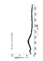
図1は薄帯のX線回折結果を示し、この薄帯においては2θ≒31°に幅広のハローパターンが観察され、このことから薄帯の金属組織は非晶質単相組織であることが判明した。このNd70Cu20C10合金の結晶化温度Txは190.7℃であった。また薄帯の液相発生温度Tmは540.3℃であって易融化が図られていた。さらに薄帯は、高い靱性を有するので、180°密着曲げが可能であり、また変色もなく優れた耐酸化性を備えていた。さらにまた前記製造条件において、冷却ロールの周速のみを変えて薄帯の厚さを20μmから400μmまで変化させ、非晶質単相組織が得られる薄帯の臨界厚さを求めたところ、その臨界厚さは270μmであることが判明した。
【0018】
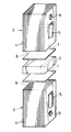
次に、厚さ100μmの薄帯に打抜き加工を施して、図2に示すように縦10mm、横10mmで非晶質の薄片状ろう材1を作製し、このろう材1を用いて次のような方法でろう接を行った。
【0019】
一方の被接合部材として、縦10mm、横10mm、厚さ3mmのNdFeB系永久磁石素材(住友特殊金属社製、商品名NEOMAX−28UH、キュリー点310℃)2を選定し、また他方の被接合部材として、厚さ0.3mmの冷間圧延鋼板4を積層してなり、且つ縦10mm、横10mm、長さ15mmの直方体状の積層体3を選定した。この場合、各鋼板4の接合にはかしめ手段5が用いられている。
【0020】
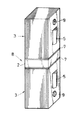
図2に示すように、1つの積層体3の鋼板端面よりなる接合面6上に1つのろう材1を、またろう材1の上に永久磁石素材2を、さらに永久磁石素材2の上にもう1つのろう材1を、さらにまたろう材1の上にもう1つの積層体3をその接合面6を下向きにしてそれぞれ重ね合わせて重ね合せ物を作製した。次いで、その重ね合せ物を真空加熱炉内に設置し、加熱温度T=550℃、加熱時間15分間の加熱工程、それに次ぐ炉冷よりなる冷却工程を行って、図3に示すように2つの積層体3により永久磁石素材2を挟むようにそれら2,3をろう材1より形成された結晶質の接合層7を介しろう接した接合体8を得た。このろう接においては、加熱温度TがT=550℃であって、ろう材1の液相発生温度Tm=540.3℃を超えているので、ろう材1は固液共存状態となる。なお、両積層体3に存する貫通孔9は引張り試験においてチャックとの連結に用いられる。
【0021】
比較のため、前記同様の永久磁石素材2と前記同様の2つの積層体3とをエポキシ樹脂系接着剤(日本チバガイギ社製、商品名アラルダイト)を介し重ね合せて前記同様の重ね合せ物を作製した。次いで、その重ね合せ物を乾燥炉内に設置して、加熱温度200℃、加熱時間60分間の加熱工程、それに次ぐ炉冷よりなる接合処理を行って、2つの積層体3と永久磁石素材2とをエポキシ樹脂系接着剤を介して接合した前記同様の接合体を得た。
【0022】
ろう材1を用いた接合体8、およびエポキシ樹脂系接着剤を用いた接合体について室温下で引張り試験を行ったところ、表1の結果を得た。
【0023】
【表1】
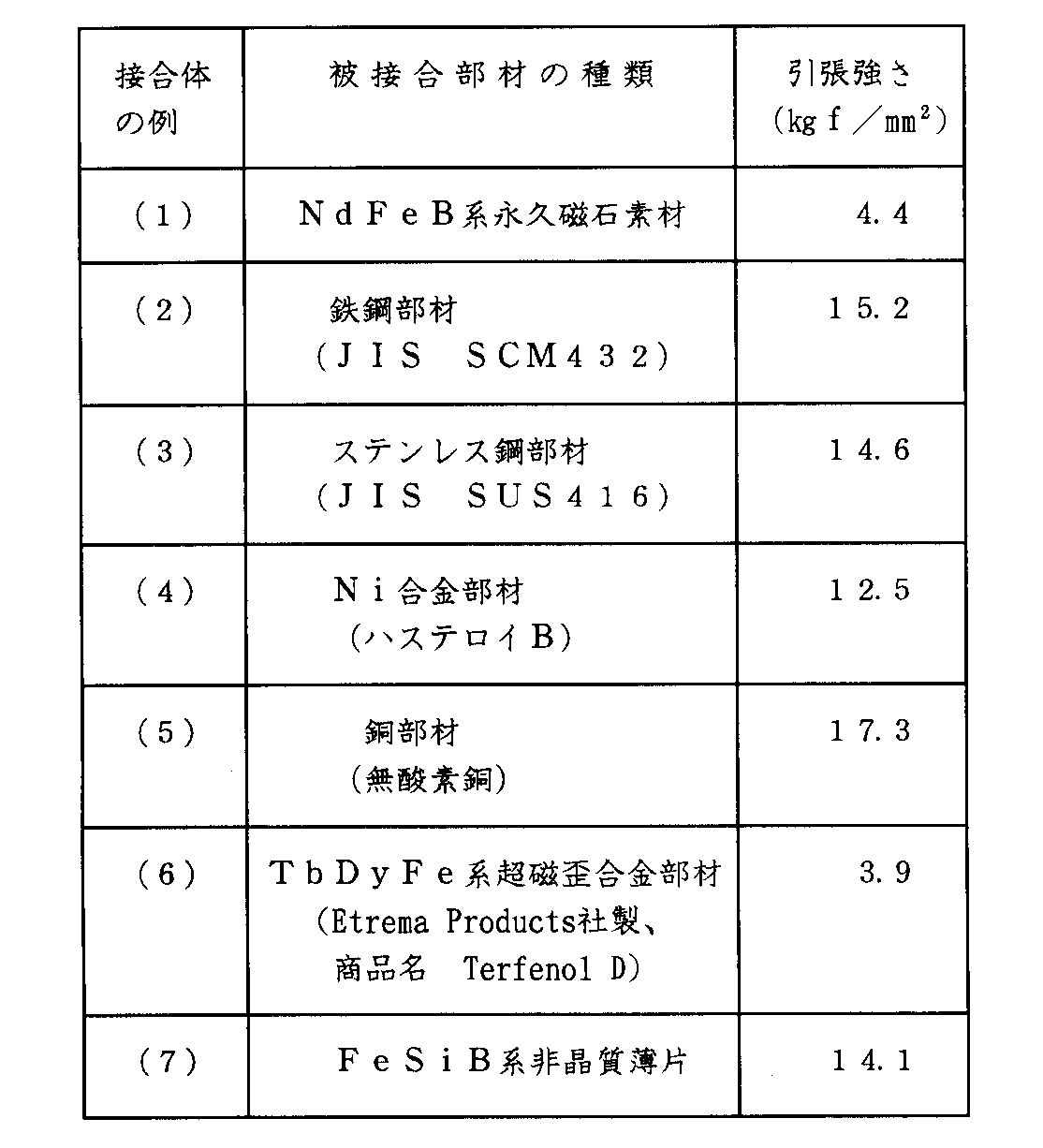
表1から明らかなように、ろう材1を用いた接合体8は、エポキシ樹脂系接着剤を用いた接合体に比べて接合強度が高く、またそのばらつきも小さかった。この接合強度の向上には、非晶質のろう材1が優れた耐酸化性を有すると共に均質であること、接合層内に酸化物が混在しないこと等も寄与している。
【0025】
NdFeB系永久磁石素材、SmCo系永久磁石素材等の希土類元素を含む永久磁石素材2は、ろう接時の加熱温度TがT>650℃になると、その磁石特性、特に保磁力 IHC (磁化の強さI=0)が低下傾向となる。ただし、残留磁束密度Brおよび保磁力 BHC (磁束密度B=0)は殆ど変わらず、したがって最大磁気エネルギ積(BH)maxは略一定である。前記ろう接においては、その加熱温度TがT=550℃であってT≦650℃であるから、永久磁石素材2の磁石特性を変化させるようなことはない。
【0026】
また前記永久磁石素材2の濡れ性の悪さは、その結晶粒界に希土類元素濃度、この実施例ではNd濃度の高い相が存在していることに起因する。前記ろう接において、そのろう材1は液相状態となっており、そのNdを主成分とするNd70Cu20C10合金より生じた液相は、高活性であると共に前記結晶粒界に存するNd濃度の高い相と主成分を共通にすることから永久磁石素材2に対して優れた濡れ性を発揮し、また前記高活性化に伴い鋼板4よりなる積層体3に対する濡れ性も極めて良好である。
【0027】
したがって、前記のようなろう材1を用いることによって、永久磁石素材2の磁石特性に影響を与えることなく、その永久磁石素材2と積層体3とを強固に接合することができる。
【0028】
前記接合技術は、回転電機としてのモータにおいて、ロータ用成層鉄心に対する永久磁石素材2のろう接に適用され、回転数が10000rpm 以上である高速回転モータの実現を可能にするものである。
【0029】
次に、前記同様の単ロール法を採用して各種組成を持つ非晶質の薄帯を製造し、また各薄帯についてX線回折等を行い、さらに前記同様のろう接および接合体に関する引張り試験を行った。表2は、その結果を示す。この場合、ろう接時の加熱温度Tは前記同様に550℃に設定され、したがってろう材1は液相状態または固液共存状態となる。表2には、前記Nd70Cu20C10合金よりなる薄帯およびろう材1に関するデータも例(20)として記載されている。
【0030】
【表2】
表2において、ろう材1の液相発生温度Tmは422.4℃≦Tm≦540.3℃であり、このことから各例において易融化が図られていることが判る。
【0032】
また結晶化温度Txは非晶質相が結晶質相に変化する温度であるから、この結晶化温度Txが高い程非晶質相が安定して存在する、と言える。
【0033】
さらに臨界厚さは希土類合金の非晶質相形成能の程度を示し、この臨界厚さが大きい程非晶質相形成能が高く、したがって非晶質薄帯を安定して製造することが可能である。
〔実施例2〕
この実施例ではNd−Cu−Al系希土類合金ろう材について述べる。
【0034】
純度99.9%のNdと、純度99.9%のCuと、純度99.9%のAlとを、Nd70Cu25Al5 合金が得られるように秤量し、次いでその秤量物を真空溶解炉を用いて溶解し、その後鋳造を行ってインゴットを得た。
【0035】
このインゴットから約50gの原料を採取し、これを石英ノズル内で高周波溶解して溶湯を調製し、次いで溶湯を石英ノズルのスリットから、その下方で高速回転するCu製冷却ロール外周面にアルゴンガス圧により噴出させて超急冷し、幅30mm、厚さ100μmのNd70Cu25Al5 合金よりなる薄帯を得た。
【0036】
この場合の製造条件は次の通りである。即ち、石英ノズルの内径 40mm、スリットの寸法 幅 0.25mm、長さ 30mm、アルゴンガス圧 1.0kgf/cm2 、溶湯温度 670℃、スリットと冷却ロールとの距離 1.0mm、冷却ロールの周速 13m/sec 、溶湯の冷却速度 約105 K/sec である。
【0037】
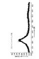
図4は薄帯のX線回折結果を示し、この薄帯においては2θ≒32°に幅広のハローパターンが観察され、このことから薄帯の金属組織は非晶質単相組織であることが判明した。また薄帯は高い靱性を有し、180°密着曲げが可能であった。
【0038】
Nd、CuおよびAlの配合量を種々変更し、前記と同様の方法で各種組成の薄帯を製造した。
【0039】
各薄帯について、その80%以上が液相となる溶融温度、金属組織、薄帯形成性および耐酸化性の有無を調べたところ、表3の結果を得た。表3には前記Nd70Cu25Al5 合金よりなる薄帯に関するデータも例(11)として記載されている。金属組織の欄において、「A」は非晶質単相組織であることを示し、これは以下同じである。また「A+C」は非晶質相Aと結晶質相Cとの混相組織であることを示す。
【0040】
【表3】
表3から明らかなように、Nd−Cu−Al系希土類合金薄帯において、易融化を図り、また非晶質化を達成し、さらに薄帯形成性および耐酸化性を良好にするためには、図5にも示すごとく例(4)〜(13)のように、Ndの含有量を68原子%≦Nd≦70原子%に、Cuの含有量を22原子%≦Cu≦30原子%に、Alの含有量を2原子%≦Al≦8原子%にそれぞれ設定すれば良い。
【0042】
次に、Nd70Cu25Al5 合金よりなる非晶質の薄帯の例(11)に打抜き加工を施して、図2に示すように縦10mm、横10mm、厚さ100μmで非晶質の薄片状ろう材1を作製し、このろう材1を用いて次のような方法でろう接を行った。
【0043】
一方の被接合部材として、実施例1と同様に、縦10mm、横10mm、厚さ3mmのNdFeB系永久磁石素材(住友特殊金属社製、商品名NEOMAX−28UH、キュリー点310℃)2を選定し、また他方の被接合部材として、実施例1と同様に、厚さ0.3mmの冷間圧延鋼板4を積層してなり、且つ縦10mm、横10mm、長さ15mmの直方体状の積層体3を選定した。
【0044】
図2に示すように、1つの積層体3の鋼板端面よりなる接合面6上に1つのろう材1を、またろう材1の上に永久磁石素材2を、さらに永久磁石素材2の上にもう1つのろう材1を、さらにまたろう材1の上にもう1つの積層体3をその接合面6を下向きにしてそれぞれ重ね合わせて重ね合せ物を作製した。次いで、その重ね合せ物を真空加熱炉内に設置し、加熱温度T=510℃、加熱時間30分間の加熱工程、それに次ぐ炉冷よりなる冷却工程を行って、図3に示すように2つの積層体3により永久磁石素材2を挟むようにそれら2,3をろう材1より形成された結晶質の接合層7を介しろう接した接合体8を得た。このろう接においては、加熱温度Tが510℃であって、ろう材1の前記溶融温度506.7℃を超えているので、ろう材1は液相状態となる。
【0045】
比較のため、Nd70Cu30合金よりなる厚さ100μmの非晶質の薄帯に打抜き加工を施して縦10mm、横10mmのろう材を作製し、このろう材を用いて前記と同様の方法で図3に示す接合体8と同一構造の接合体を得た。この場合、Nd70Cu30合金は共晶合金であり、その共晶点は520℃であることから、加熱温度Tは530℃に設定された。
【0046】
Nd70Cu25Al5 合金ろう材1を用いた接合体8およびNd70Cu30合金ろう材を用いた接合体について室温下および150℃の加熱下で引張り試験を行ったところ、表4の結果を得た。
【0047】
【表4】
表4から明らかなように、Nd70Cu25Al5 合金ろう材1を用いた接合体8は、ろう接時の加熱温度Tが510℃であって、Nd70Cu30合金ろう材を用いた場合の530℃に比べて20℃も低く設定されているにも拘らず、室温下および150℃の加熱下において、Nd70Cu30合金ろう材を用いた場合と略同等の接合強度を有する。これはNd70Cu25Al5 合金において易融化が図られていることに因る。
〔実施例3〕
この実施例ではRE−Cu−Al系希土類合金について述べる。
(1) 純度99.9%のPrと、純度99.9%のCuと、純度99.9%のAlとを、Pr68Cu27Al5 合金が得られるように秤量し、次いでその秤量物を真空溶解炉を用いて溶解し、その後鋳造を行ってインゴットを得た。
【0049】
このインゴットから約50gの原料を採取し、これを石英ノズル内で高周波溶解して溶湯を調製し、次いで溶湯を石英ノズルのスリットから、その下方で高速回転するCu製冷却ロール外周面にアルゴンガス圧により噴出させて超急冷し、幅30mm、厚さ100μmのPr68Cu27Al5 合金よりなる薄帯を得た。
【0050】
この場合の製造条件は次の通りである。即ち、石英ノズルの内径 40mm、スリットの寸法 幅 0.25mm、長さ 30mm、アルゴンガス圧 1.0kgf/cm2 、溶湯温度 580℃、スリットと冷却ロールとの距離 1.0mm、冷却ロールの周速 13m/sec 、溶湯の冷却速度 約105 K/sec である。
【0051】
図6は薄帯のX線回折結果を示し、この薄帯においては2θ≒32°に幅広のハローパターンが観察され、このことから薄帯の金属組織は非晶質単相組織であることが判明した。また薄帯は高い靱性を有し、180°密着曲げが可能であった。
【0052】
Pr、CuおよびAlの配合量を変更して、前記と同様の方法で各種組成を有し、且つ前記と同一寸法の非晶質薄帯を製造した。
【0053】
各薄帯について、その80%以上が液相となる溶融温度、金属組織、薄帯形成性および耐酸化性の有無を調べたところ、表5の結果を得た。表5には前記Pr68Cu27Al5 合金よりなる薄帯に関するデータも例(4)として記載されている。
【0054】
【表5】
またMm(58原子%Ce、24原子%La、13原子%Nd、5原子%Pr)、CuおよびAlの配合量を変更して、前記と同様の方法で各種組成を有し、且つ前記と同一寸法の非晶質薄帯を製造した。
【0056】
各薄帯について、その80%以上が液相となる溶融温度、金属組織、薄帯形成性および耐酸化性の有無を調べたところ、表6の結果を得た。
【0057】
【表6】
さらにAlの配合量を5原子%(一定)とし、また希土類元素REの種類およびその配合量ならびにCuの配合量を変更して、前記と同様の方法で各種組成を有し、且つ前記と同一寸法の非晶質薄帯を製造した。
【0059】
各薄帯について、その液相発生温度Tm、金属組織、薄帯形成性および耐酸化性の有無を調べたところ、表7の結果を得た。
【0060】
【表7】
表5〜7から明らかなように、各薄帯、したがってRE−Cu−Al合金において液相発生温度Tmは380℃≦Tm≦600℃の範囲にあって易融化が図られている。この易融化達成のためには、希土類元素REの含有量を57原子%≦RE<80原子%に、Cuの含有量を18原子%≦Cu<40原子%に、Alの含有量をAl≦20原子%にそれぞれ設定し、希土類元素REとしてLa、Ce、Pr、NdおよびSmから選択される少なくとも一種を用いればよい。なお、Ndを含む薄帯は表3の例(11)に示されている。
【0062】
特に、Pr−Cu−Al系希土類合金薄帯において、易融化を図り、また非晶質化を達成し、さらに薄帯形成性および耐酸化性を良好にするためには、表5に示すように、Prの含有量を60原子%≦Pr≦70原子%に、Cuの含有量を20原子%≦Cu≦30原子%に、Alの含有量を5原子%≦Al≦20原子%にそれぞれ設定すれば良い。
(2)−1.表5に示した、Pr68Cu27Al5 合金よりなる非晶質の薄帯の例(4)に打抜き加工を施して、図2に示すように縦10mm、横10mm、厚さ100μmで非晶質の薄片状ろう材1を作製し、このろう材1を用いて次のような方法でろう接を行った。
【0063】
一方の被接合部材として、実施例1と同様に、縦10mm、横10mm、厚さ3mmのNdFeB系永久磁石素材(住友特殊金属社製、商品名NEOMAX−28UH、キュリー点310℃)2を選定し、また他方の被接合部材として、実施例1と同様に、厚さ0.3mmの冷間圧延鋼板4を積層してなり、且つ縦10mm、横10mm、長さ15mmの直方体状の積層体3を選定した。
【0064】
図2に示すように、1つの積層体3の鋼板端面よりなる接合面6上に1つのろう材1を、またろう材1の上に永久磁石素材2を、さらに永久磁石素材2の上にもう1つのろう材1を、さらにまたろう材1の上にもう1つの積層体3をその接合面6を下向きにしてそれぞれ重ね合わせて重ね合せ物を作製した。次いで、その重ね合せ物を真空加熱炉内に設置し、加熱温度T=440℃、加熱時間15分間の加熱工程、それに次ぐ炉冷よりなる冷却工程を行って、図3に示すように2つの積層体3により永久磁石素材2を挟むようにそれら2,3をろう材1より形成された結晶質の接合層7を介しろう接した接合体8の例(1)を得た。このろう接においては、加熱温度Tが440℃であって、ろう材1の前記溶融温度427.3℃を超えているので、ろう材1は液相状態となる。
【0065】
比較のため、永久磁石素材2に代えて、それと同一寸法の各種被接合部材を用い前記同様のろう接を行って接合体8の例(2)〜(6)を得た。さらに永久磁石素材2に代えて、縦10mm、横10mm、厚さ25μmのFeSiB系非晶質薄片(アライド社製、商品名 260SS−2)を用いると共に前記ろう材1として厚さ20μmのもの(Pr68Cu27Al5 合金)を用い前記同様のろう接を行って接合体8の例(7)を得た。
【0066】
各接合体8の例(1)〜(7)について室温下にて引張り試験を行ったところ、表8の結果を得た。
【0067】
【表8】
表8において、例(2)〜(5),(7)の場合は接合層7にて破断を生じていたが、例(1)の場合は永久磁石素材2が破断し、また例(6)の場合は超磁歪合金部材が破断していた。表8より、加熱温度Tが440℃といったように低いにも拘らず、大きな接合強度が得られることが判る。
【0069】
炭素鋼、合金鋼およびステンレス鋼より構成された部材は焼入処理により硬化されるが、750℃〜900℃に加熱されると焼なまされて軟化し、また希土類系超磁歪合金部材の場合、900℃以上に加熱されると金属組織が変化するため磁気特性が影響を受ける、といった不具合を生じるが、前記ろう材1によるろう接では加熱温度Tが低いので、前記不具合の発生を回避することができる。
(2)−2.表6に示したMm72Cu23Al5 合金よりなる非晶質の薄帯の例(5)より前記同様の方法でろう材1を作製し、このろう材1を用い前記同様のろう接を行って、前記同様の接合体8の例(1)〜(6)を得た。また前記同様の方法で前記同様の接合体8の例(7)を得た。ただし、加熱温度Tは420℃に設定された。
【0070】
表9は各接合体8の例(1)〜(7)に関する引張り試験結果を示す。
【0071】
【表9】
表9において、前記同様に例(2)〜(5),(7)の場合は接合層7にて破断を生じていたが、例(1)の場合は永久磁石素材2が破断し、また例(6)の場合は超磁歪合金部材が破断していた。表9より、加熱温度Tが420℃といったように低いにも拘らず、大きな接合強度が得られることが判る。
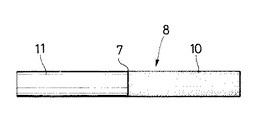
(2)−3.表5に示した、Pr68Cu27Al5 合金よりなる非晶質の薄帯の例(4)に打抜き加工を施して、図7に示すように直径6mm、厚さ100μmで非晶質の薄片状ろう材1を作製し、このろう材1を用いて次のような方法でろう接を行った。
【0073】
一方の被接合部材として、直径6mm、長さ20mmの超磁歪合金(Fe66Sm33Yb1 合金)部材10を選定し、また他方の被接合部材として、直径6mm、長さ20mmのステンレス鋼(JIS SUS410)部材11を選定した。
【0074】
超磁歪合金部材10とステンレス鋼部材11との間にろう材1を介在させて、それら1,10,11を所定の治具により固定した。次いで、このように固定された20個の組合せ物を真空加熱炉内に設置し、加熱温度T=445℃、加熱時間5分間の加熱工程、それに次ぐ炉冷よりなる冷却工程を行って、図8に示すように超磁歪合金部材10とステンレス鋼部材11とをろう材1より形成された結晶質の接合層7を介しろう接した20個の接合体8を得た。このろう接においては、加熱温度Tが445℃であって、ろう材1の前記溶融温度427.3℃を超えているので、ろう材1は液相状態となる。
【0075】
次いで、各接合体8についてJIS R1601に則って4点曲げ試験を行った。即ち、接合体8の両端部をそれぞれ支点で支え、また接合層7の両側にそれぞれ荷重点を設け、クロスヘッド速度0.5mm/min にて荷重を付与した。その結果、各接合体8はその超磁歪合金部材10において破断し、平均曲げ強さは6.5kgf/mm2 であった。これにより加熱温度Tが445℃といったように低いにも拘らず、大きな接合強度が得られることが判る。
【0076】
【発明の効果】
本発明によれば、特定の希土類元素RE、Cuおよび特定の合金元素AEを特定量含有させることにより、易融化を達成され、各種被接合部材の接合材として好適な希土類合金ろう材を提供することができる。
【0077】
また市販の軟ろうは融点が390℃以下であり、一方、硬ろうは融点が570℃以上である。本発明によれば、このような軟ろうおよび硬ろうでは達成し得ない温度範囲、つまり390〜570℃においてろう接を行うことが可能な希土類合金ろう材を提供することができる。
【図面の簡単な説明】
【図1】Nd70Cu20C10合金のX線回折図である。
【図2】ろう材、永久磁石素材および積層体の重ね合せ関係を示す斜視図である。
【図3】接合体の一例を示す斜視図である。
【図4】Nd70Cu25Al5 合金のX線回折図である。
【図5】Nd−Cu−Al系合金の組成図である。
【図6】Pr68Cu27Al5 合金のX線回折図である。
【図7】ろう材、超磁歪合金部材およびステンレス鋼部材の重ね合せ関係を示す斜視図である。
【図8】接合体の他例を示す正面図である。
【符号の説明】
1 ろう材
2 永久磁石
3 積層体
8 接合体[0001]
TECHNICAL FIELD OF THE INVENTION
The present invention relates to a brazing material made of a rare earth alloy, which is suitable as a joining material for a rare earth alloy brazing material, for example, a permanent magnet material, a giant magnetostrictive alloy member, or the like.
[0002]
[Prior art]
For example, a permanent magnet material containing a rare earth element is very brittle and has poor machinability, and when exposed to a high temperature, has a property that the metal structure changes and accordingly the magnet characteristics are affected.
[0003]
For this reason, for example, when a permanent magnet material is attached to the rotor core of the motor, attachment means such as a bayonet structure, screwing, welding, or the like cannot be adopted, and an adhesive is conventionally used.
[0004]
[Problems to be solved by the invention]
However, when an adhesive is used, there arises a problem that the bonding strength is low due to poor wettability of the permanent magnet material, and the bonding strength is remarkably reduced with increasing temperature. Under such circumstances, it is impossible to respond to the demand for high-speed rotation of the motor.
[0005]
[Means for Solving the Problems]
In view of the above, an object of the present invention is to provide the rare earth alloy brazing material having a relatively low liquid phase generation temperature and suitable as a joining material for various members to be joined such as a permanent magnet material.
[0006]
According to the present invention, in order to achieve the above object, the content of the rare earth element RE is RE ≧ 50 atomic%, the content of Cu is 18 atomic% ≦ Cu <40 atomic%, and the content of the other alloying element AE is AE. ≦ 20 at%, and the alloying element AE is Fe, Co, Ni, Ru, Rh, Pd, Os, Ir, Pt, Ag, Au, Zn, B, Al, Ga, In, C, Si, Ge, A rare earth alloy brazing material is provided, which is at least one selected from Sn, Pb, P, Sb and Bi.
[0007]
When the contents of the rare earth elements RE, Cu, and the alloying element AE are specified as described above, the eutectic reaction between the rare earth element RE, Cu, and the alloying element AE under heating causes the liquid phase generation of the rare earth alloy brazing material. The temperature Tm is relatively low, that is, easy melting is achieved. Since the liquid phase generated from the rare-earth alloy brazing material is highly active, the rare-earth alloy brazing material in the liquid phase or in the solid-liquid coexistence state exhibits good wettability to members to be joined of various materials. It manifests the diffusion phenomenon. In addition, the rare earth alloy brazing material exhibits good diffusibility to members to be joined of various materials even in a solid state under heating. By using such a rare earth alloy brazing material, it is possible to strongly braze both members to be joined at a relatively low temperature, and therefore, this brazing material is used for joining various members to be joined such as a material for permanent magnets. It is suitable as a material.
[0008]
A rare earth alloy containing Cu becomes amorphous, for example, by applying a liquid quenching method. When the rare earth alloy contains the alloy element AE in a specific amount, the amorphous element is promoted to be amorphous and the continuity in forming into a thin ribbon shape is improved. Can be easily obtained from the amorphous alloy having a thickness of about 10 to about 100 μm and homogenization achieved.
[0009]
It is possible to obtain a rare earth alloy brazing material from such a ribbon. In this case, since the ribbon has high toughness, a brazing material can be formed into a desired shape by performing a cutting process such as a punching process on the ribbon. In addition, the brazing material has excellent oxidation resistance because it does not have a grain boundary layer serving as a starting point of oxidation. In addition, when brazing, the required thickness of the brazing material can be adjusted simply by laminating the flakes. There is no mixing in the formed bonding layer.
[0010]
The thickness of the ribbon is adjusted by the peripheral speed of the cooling roll, the injection pressure of the molten metal, the temperature of the molten metal, and the like, and the thickness is 1/2 to 1/10 of that cut out from the ingot.
[0011]
However, when the content of the rare earth element RE in the rare earth alloy brazing material is RE <50 atomic%, the liquid phase generation temperature Tm tends to increase, and the bonding strength decreases. When the Cu content is Cu <18 atomic%, it is difficult to achieve the amorphization. On the other hand, when Cu ≧ 40 atomic%, the liquid phase generation temperature Tm increases. When the content of the alloy element AE is AE> 20 atomic%, the continuity and homogeneity of the ribbon made of the amorphous alloy are deteriorated.
[0012]
BEST MODE FOR CARRYING OUT THE INVENTION
The rare earth alloy brazing material is composed of the rare earth elements RE and Cu and another alloy element AE. The content of the rare earth element RE is set to RE ≧ 50 atomic%, the content of Cu is set to 18 atomic% ≦ Cu <40 atomic%, and the content of the alloying element AE is set to AE ≦ 20 atomic%.
[0013]
The rare earth element RE is at least one selected from Sc, Y, and a lanthanoid, that is, 17 kinds of elements, and they are used in the form of a simple substance or a mixture of Mm (misch metal) or Di (didium). The alloy elements AE are Fe, Co, Ni, Ru, Rh, Pd, Os, Ir, Pt, Ag, Au, Zn, B, Al, Ga, In, C, Si, Ge, Sn, Pb, P, and Sb. And at least one selected from Bi.
[Example 1]
In this embodiment, a Nd-Cu-AE-based rare earth alloy brazing material will be described.
[0014]
Nd having a purity of 99.9%, Cu having a purity of 99.9%, and C having a purity of 99.9% were converted into Nd. 70 Cu 20 C 10 The alloy was weighed so as to obtain an alloy (the unit of the value is atomic%, the same in the following examples), and then the weighed material was melted using a vacuum melting furnace, and then cast to obtain an ingot.
[0015]
Approximately 50 g of the raw material was collected from this ingot, and this was melted at a high frequency using a quartz nozzle to prepare a molten metal. Then, the molten metal was passed through the slit of the quartz nozzle and applied to the outer peripheral surface of a Cu cooling roll rotating at a high speed below the argon gas pressure. Nd with a width of 30 mm and a thickness of 20 μm 70 Cu 20 C 10 A ribbon made of an alloy was obtained. The ribbon is homogeneous and has good continuity, so that the alloy having the above composition has good ribbon forming properties.
[0016]
The manufacturing conditions in this case are as follows. That is, the inner diameter of the quartz nozzle is 40 mm, the dimensions of the slit are 0.25 mm in width, 30 mm in length, and the argon gas pressure is 1.0 kgf / cm. 2 , Melt temperature 800 ° C, distance between slit and cooling roll 1.0mm, peripheral speed of cooling roll 33m / sec, cooling rate of molten metal about 10 5 K / sec.
[0017]
FIG. 1 shows the result of X-ray diffraction of the ribbon. In this ribbon, a wide halo pattern was observed at 2θ ≒ 31 °, which indicates that the metal structure of the ribbon was an amorphous single-phase structure. found. This Nd 70 Cu 20 C 10 The crystallization temperature Tx of the alloy was 190.7 ° C. Further, the liquid phase generation temperature Tm of the ribbon was 540.3 ° C., so that easy melting was achieved. Furthermore, since the ribbon had high toughness, it could be bent 180 ° in close contact and had excellent oxidation resistance without discoloration. Furthermore, under the above manufacturing conditions, the thickness of the ribbon was changed from 20 μm to 400 μm by changing only the peripheral speed of the cooling roll, and the critical thickness of the ribbon from which an amorphous single-phase structure was obtained was determined. The critical thickness was found to be 270 μm.
[0018]
Next, a thin strip having a thickness of 100 μm is punched to produce an amorphous
[0019]
As one member to be joined, a NdFeB-based permanent magnet material (manufactured by Sumitomo Special Metals Co., Ltd., trade name NEOMAX-28UH, Curie point 310 ° C.) 2 having a length of 10 mm, a width of 10 mm and a thickness of 3 mm is selected, and the other member to be joined As a member, a
[0020]
As shown in FIG. 2, one
[0021]
For comparison, the same
[0022]
When a tensile test was performed at room temperature on the joined
[0023]
[Table 1]
As is clear from Table 1, the joined
[0025]
When the heating temperature T at the time of brazing becomes T> 650 ° C., the
[0026]
The poor wettability of the
[0027]
Therefore, by using the
[0028]
The joining technique is applied to brazing of the
[0029]
Next, an amorphous ribbon having various compositions is manufactured by employing the same single roll method as described above, and X-ray diffraction and the like are performed on each ribbon. The test was performed. Table 2 shows the results. In this case, the heating temperature T at the time of brazing is set to 550 ° C. as described above, so that the
[0030]
[Table 2]
In Table 2, the liquid phase generation temperature Tm of the
[0032]
Since the crystallization temperature Tx is a temperature at which the amorphous phase changes to a crystalline phase, it can be said that the higher the crystallization temperature Tx, the more stable the amorphous phase exists.
[0033]
Furthermore, the critical thickness indicates the degree of the ability of the rare earth alloy to form an amorphous phase, and the greater the critical thickness, the higher the ability to form an amorphous phase, and therefore, it is possible to stably produce an amorphous ribbon. .
[Example 2]
In this embodiment, a Nd-Cu-Al-based rare earth alloy brazing material will be described.
[0034]
Nd having a purity of 99.9%, Cu having a purity of 99.9%, and Al having a purity of 99.9% were converted into Nd. 70 Cu 25 Al 5 The alloy was weighed so as to obtain an alloy, and the weighed material was melted using a vacuum melting furnace, and then cast to obtain an ingot.
[0035]
Approximately 50 g of the raw material was collected from this ingot, and the raw material was melted at a high frequency in a quartz nozzle to prepare a molten metal. Then, the molten metal was passed through a slit of the quartz nozzle to an outer peripheral surface of a Cu cooling roll rotating at a high speed below the argon gas. Spouted by pressure and super-cooled, Nd of 30mm width and 100μm thickness 70 Cu 25 Al 5 A ribbon made of an alloy was obtained.
[0036]
The manufacturing conditions in this case are as follows. That is, the inner diameter of the quartz nozzle is 40 mm, the dimensions of the slit are 0.25 mm in width, 30 mm in length, and the argon gas pressure is 1.0 kgf / cm. 2 The temperature of the molten metal is 670 ° C., the distance between the slit and the cooling roll is 1.0 mm, the peripheral speed of the cooling roll is 13 m / sec, and the cooling speed of the molten metal is about 10 5 K / sec.
[0037]
FIG. 4 shows the results of X-ray diffraction of the ribbon. In this ribbon, a wide halo pattern was observed at 2θ ≒ 32 °, which indicates that the metal structure of the ribbon was an amorphous single-phase structure. found. Further, the ribbon had high toughness and could be bent 180 ° in close contact.
[0038]
Various amounts of Nd, Cu and Al were varied, and ribbons of various compositions were produced in the same manner as described above.
[0039]
For each ribbon, the melting temperature at which 80% or more of the ribbon becomes a liquid phase, the metal structure, the ribbon-forming properties, and the presence or absence of oxidation resistance were examined. The results shown in Table 3 were obtained. Table 3 shows the Nd 70 Cu 25 Al 5 Data on a ribbon made of an alloy is also described as Example (11). In the column of metallographic structure, “A” indicates that it is an amorphous single-phase structure, which is the same hereinafter. “A + C” indicates a mixed phase structure of the amorphous phase A and the crystalline phase C.
[0040]
[Table 3]
As is evident from Table 3, in the Nd-Cu-Al-based rare-earth alloy ribbon, in order to facilitate fusibility, achieve amorphousization, and further improve the ribbon-forming property and oxidation resistance, As shown in FIG. 5, as in Examples (4) to (13), the content of Nd is reduced to 68 atomic% ≦ Nd ≦ 70 atomic%, and the content of Cu is reduced to 22 atomic% ≦ Cu ≦ 30 atomic%. , Al content may be set to 2 atomic% ≦ Al ≦ 8 atomic%.
[0042]
Next, Nd 70 Cu 25 Al 5 Punching is performed on the amorphous ribbon example (11) made of an alloy to produce an amorphous
[0043]
As one member to be joined, a NdFeB-based permanent magnet material (manufactured by Sumitomo Special Metals Co., Ltd., trade name NEOMAX-28UH, Curie point 310 ° C.) 2 having a length of 10 mm, a width of 10 mm and a thickness of 3 mm is selected as in the first embodiment. In addition, as another member to be joined, a cold rolled
[0044]
As shown in FIG. 2, one
[0045]
For comparison, Nd 70 Cu 30 A 100 μm-thick amorphous ribbon made of an alloy is punched to form a brazing material having a length of 10 mm and a width of 10 mm, and using the brazing material in the same manner as described above, the joined
[0046]
Nd 70 Cu 25 Al 5 Joint 8 and Nd using
[0047]
[Table 4]
As is apparent from Table 4, Nd 70 Cu 25 Al 5 The joined
[Example 3]
In this embodiment, a RE-Cu-Al-based rare earth alloy will be described.
(1) Pr of 99.9% purity, Cu of 99.9% purity, and Al of 99.9% purity were converted into Pr 68 Cu 27 Al 5 The alloy was weighed so as to obtain an alloy, and the weighed material was melted using a vacuum melting furnace, and then cast to obtain an ingot.
[0049]
Approximately 50 g of the raw material was collected from this ingot, and the raw material was melted at a high frequency in a quartz nozzle to prepare a molten metal. Then, the molten metal was passed through a slit of the quartz nozzle to an outer peripheral surface of a Cu cooling roll rotating at a high speed below the argon gas. Super-rapid cooling by spouting with pressure, Pr of 30 mm width and 100 μm thickness 68 Cu 27 Al 5 A ribbon made of an alloy was obtained.
[0050]
The manufacturing conditions in this case are as follows. That is, the inner diameter of the quartz nozzle is 40 mm, the dimensions of the slit are 0.25 mm in width, 30 mm in length, and the argon gas pressure is 1.0 kgf / cm. 2 Melt temperature 580 ° C., distance between slit and cooling roll 1.0 mm, cooling roll peripheral speed 13 m / sec, cooling rate of melt about 10 5 K / sec.
[0051]
FIG. 6 shows the result of X-ray diffraction of the ribbon. In this ribbon, a broad halo pattern was observed at 2θ ≒ 32 °, which indicates that the metal structure of the ribbon was an amorphous single-phase structure. found. Further, the ribbon had high toughness and could be bent 180 ° in close contact.
[0052]
By changing the amounts of Pr, Cu and Al, amorphous ribbons having various compositions and the same dimensions as those described above were produced in the same manner as described above.
[0053]
With respect to each ribbon, the melting temperature, the metal structure, the formation of the ribbon, and the presence or absence of oxidation resistance at which 80% or more of the ribbon became a liquid phase were examined. The results shown in Table 5 were obtained. Table 5 shows the Pr 68 Cu 27 Al 5 Data on a ribbon made of an alloy is also described as Example (4).
[0054]
[Table 5]
Further, Mm (58 at% Ce, 24 at% La, 13 at% Nd, 5 at% Pr), the composition of Cu and Al were changed, and various compositions were obtained in the same manner as described above. Amorphous ribbons of the same dimensions were produced.
[0056]
With respect to each ribbon, the melting temperature at which 80% or more of the ribbon becomes a liquid phase, the metal structure, the formation of the ribbon, and the presence or absence of oxidation resistance were examined.
[0057]
[Table 6]
Further, the compounding amount of Al was set to 5 atomic% (constant), and the kind and the compounding amount of the rare earth element RE and the compounding amount of Cu were changed to have various compositions in the same manner as described above, and the same as above. Amorphous ribbons of dimensions were produced.
[0059]
For each ribbon, the liquid phase generation temperature Tm, metal structure, ribbon forming property and oxidation resistance were examined. The results shown in Table 7 were obtained.
[0060]
[Table 7]
As is clear from Tables 5 to 7, in each of the ribbons, that is, in the RE-Cu-Al alloy, the liquid phase generation temperature Tm is in the range of 380 ° C ≦ Tm ≦ 600 ° C., and easy melting is achieved. In order to achieve this easy melting, the content of the rare earth element RE is set to 57 atomic% ≦ RE <80 atomic%, the content of Cu is set to 18 atomic% ≦ Cu <40 atomic%, and the content of Al is set to Al ≦ It is set at 20 atomic%, and at least one selected from La, Ce, Pr, Nd and Sm may be used as the rare earth element RE. The ribbon containing Nd is shown in Example (11) of Table 3.
[0062]
In particular, in the Pr-Cu-Al-based rare earth alloy ribbon, in order to achieve easy melting, achieve amorphousization, and further improve the ribbon forming property and oxidation resistance, as shown in Table 5, The content of Pr is 60 atomic% ≦ Pr ≦ 70 atomic%, the content of Cu is 20 atomic% ≦ Cu ≦ 30 atomic%, and the content of Al is 5 atomic% ≦ Al ≦ 20 atomic%. Just set it.
(2) -1. Pr shown in Table 5 68 Cu 27 Al 5 An example of an amorphous ribbon made of an alloy is punched to produce an amorphous
[0063]
As one member to be joined, a NdFeB-based permanent magnet material (manufactured by Sumitomo Special Metals Co., Ltd., trade name NEOMAX-28UH, Curie point 310 ° C.) 2 having a length of 10 mm, a width of 10 mm and a thickness of 3 mm is selected as in the first embodiment. In addition, as another member to be joined, a cold rolled
[0064]
As shown in FIG. 2, one
[0065]
For comparison, examples (2) to (6) of the joined
[0066]
When a tensile test was performed at room temperature on Examples (1) to (7) of each bonded
[0067]
[Table 8]
In Table 8, in the cases of Examples (2) to (5) and (7), the fracture occurred in the
[0069]
The members made of carbon steel, alloy steel and stainless steel are hardened by quenching, but when heated to 750 ° C to 900 ° C, they are annealed and softened, and in the case of rare earth giant magnetostrictive alloy members However, when heated to 900 ° C. or more, the metal structure is changed, thereby affecting magnetic properties. However, since the heating temperature T is low in brazing with the
(2) -2. Mm shown in Table 6 72 Cu 23 Al 5
[0070]
Table 9 shows the results of the tensile tests on the examples (1) to (7) of the respective joined
[0071]
[Table 9]
In Table 9, in the same manner as described above, in the cases of Examples (2) to (5) and (7), the break occurred in the
(2) -3. Pr shown in Table 5 68 Cu 27 Al 5 A punching process is performed on the amorphous ribbon example (4) made of an alloy to produce an amorphous
[0073]
As one member to be joined, a giant magnetostrictive alloy (Fe 66 Sm 33 Yb 1 Alloy)
[0074]
The
[0075]
Next, a four-point bending test was performed on each joined
[0076]
【The invention's effect】
ADVANTAGE OF THE INVENTION According to this invention, melting | fusing is achieved by containing specific rare earth elements RE and Cu and specific alloying element AE in specific amounts, and the rare earth alloy brazing material suitable as a joining material of various to-be-joined members is provided. be able to.
[0077]
A commercially available soft solder has a melting point of 390 ° C. or less, while a hard solder has a melting point of 570 ° C. or more. According to the present invention, it is possible to provide a rare earth alloy brazing material capable of performing brazing in a temperature range that cannot be achieved by such a soft solder and a hard solder, that is, 390 to 570 ° C.
[Brief description of the drawings]
FIG. 1 shows Nd 70 Cu 20 C 10 It is an X-ray diffraction diagram of an alloy.
FIG. 2 is a perspective view showing an overlapping relationship between a brazing material, a permanent magnet material, and a laminate.
FIG. 3 is a perspective view showing an example of a joined body.
FIG. 4 shows Nd 70 Cu 25 Al 5 It is an X-ray diffraction diagram of an alloy.
FIG. 5 is a composition diagram of an Nd—Cu—Al-based alloy.
FIG. 6 shows Pr 68 Cu 27 Al 5 It is an X-ray diffraction diagram of an alloy.
FIG. 7 is a perspective view showing a superposition relationship of a brazing material, a giant magnetostrictive alloy member, and a stainless steel member.
FIG. 8 is a front view showing another example of the joined body.
[Explanation of symbols]
1 brazing filler metal
2 permanent magnet
3 laminate
8 Joint
Claims (8)
Priority Applications (1)
| Application Number | Priority Date | Filing Date | Title |
|---|---|---|---|
| JP01985496A JP3592425B2 (en) | 1995-02-07 | 1996-02-06 | Rare earth alloy brazing filler metal |
Applications Claiming Priority (3)
| Application Number | Priority Date | Filing Date | Title |
|---|---|---|---|
| JP7-19484 | 1995-02-07 | ||
| JP1948495 | 1995-02-07 | ||
| JP01985496A JP3592425B2 (en) | 1995-02-07 | 1996-02-06 | Rare earth alloy brazing filler metal |
Publications (2)
| Publication Number | Publication Date |
|---|---|
| JPH08276291A JPH08276291A (en) | 1996-10-22 |
| JP3592425B2 true JP3592425B2 (en) | 2004-11-24 |
Family
ID=26356313
Family Applications (1)
| Application Number | Title | Priority Date | Filing Date |
|---|---|---|---|
| JP01985496A Expired - Fee Related JP3592425B2 (en) | 1995-02-07 | 1996-02-06 | Rare earth alloy brazing filler metal |
Country Status (1)
| Country | Link |
|---|---|
| JP (1) | JP3592425B2 (en) |
Families Citing this family (6)
| Publication number | Priority date | Publication date | Assignee | Title |
|---|---|---|---|---|
| KR20030012584A (en) * | 2001-08-01 | 2003-02-12 | 주식회사삼화합금사 | an alloy composition for a filler metal and preparation method thereof |
| US6704189B2 (en) * | 2002-04-09 | 2004-03-09 | Tdk Corporation | Electronic device with external terminals and method of production of the same |
| JP4657884B2 (en) * | 2005-10-19 | 2011-03-23 | 独立行政法人科学技術振興機構 | Cerium-based metallic glass alloy and manufacturing method thereof |
| CN105290646B (en) * | 2015-12-08 | 2017-06-06 | 哈尔滨工业大学 | A multi-component high-temperature solder |
| CN108220732B (en) * | 2016-12-22 | 2019-12-31 | 有研稀土新材料股份有限公司 | Alloy material, bonded magnet and modification method of rare earth permanent magnet powder |
| TWI714825B (en) | 2018-02-07 | 2021-01-01 | 大瑞科技股份有限公司 | Solder composition alloy and tin ball |
-
1996
- 1996-02-06 JP JP01985496A patent/JP3592425B2/en not_active Expired - Fee Related
Also Published As
| Publication number | Publication date |
|---|---|
| JPH08276291A (en) | 1996-10-22 |
Similar Documents
| Publication | Publication Date | Title |
|---|---|---|
| US5830585A (en) | Article made by joining two members together, and a brazing filler metal | |
| EP0786854B1 (en) | Rotor for rotating machine, method of manufacturing same, and magnet unit | |
| US4049475A (en) | SECo5 -Permanent magnet joined to at least one iron mass and method of fabricating such a permanent magnet | |
| JP3592425B2 (en) | Rare earth alloy brazing filler metal | |
| US4508257A (en) | Method of brazing with nickel based alloy | |
| JP2008221290A (en) | Bonded body and bonding method | |
| US4405391A (en) | Homogeneous, ductile nickel-palladium brazing foils | |
| JP3441197B2 (en) | Paste joining material for brazing | |
| JP5935183B2 (en) | Method of joining magnesium alloy and joining structure of magnesium alloy | |
| US4448618A (en) | Nickel based brazing filler metals | |
| JP3802586B2 (en) | Heat joining method using brazing material for two kinds of members with different thermal expansion coefficients | |
| JP3382392B2 (en) | Brazing material | |
| JP3592397B2 (en) | Heat bonding method for two kinds of members having different thermal expansion rates | |
| JP3373950B2 (en) | Heat bonding method of two kinds of members having different thermal expansion coefficients | |
| JP3645925B2 (en) | Joined body and joining method of permanent magnet and different kind of member | |
| JP3382383B2 (en) | Bonding material for metal members | |
| JP3759198B2 (en) | Joining method of workpieces | |
| JP2008080393A (en) | Bonded body using peritectic alloy, bonding method, and semiconductor device | |
| JP5203906B2 (en) | Bi-containing solder foil manufacturing method, Bi-containing solder foil, joined body, and power semiconductor module | |
| JPH08309581A (en) | Joined body consisting of two members to be joined | |
| JPS6261398B2 (en) | ||
| JP3631809B2 (en) | Joining method of workpieces | |
| JP3759186B2 (en) | Brazing method for joined members | |
| JP3472358B2 (en) | Permanent magnet for heat bonding and method of manufacturing the same | |
| KR102303001B1 (en) | Electrode marerial for transient liquid phase sintering |
Legal Events
| Date | Code | Title | Description |
|---|---|---|---|
| A977 | Report on retrieval |
Free format text: JAPANESE INTERMEDIATE CODE: A971007 Effective date: 20040811 |
|
| TRDD | Decision of grant or rejection written | ||
| A01 | Written decision to grant a patent or to grant a registration (utility model) |
Free format text: JAPANESE INTERMEDIATE CODE: A01 Effective date: 20040818 |
|
| A61 | First payment of annual fees (during grant procedure) |
Free format text: JAPANESE INTERMEDIATE CODE: A61 Effective date: 20040825 |
|
| R150 | Certificate of patent or registration of utility model |
Free format text: JAPANESE INTERMEDIATE CODE: R150 |
|
| FPAY | Renewal fee payment (event date is renewal date of database) |
Free format text: PAYMENT UNTIL: 20070903 Year of fee payment: 3 |
|
| FPAY | Renewal fee payment (event date is renewal date of database) |
Free format text: PAYMENT UNTIL: 20080903 Year of fee payment: 4 |
|
| FPAY | Renewal fee payment (event date is renewal date of database) |
Free format text: PAYMENT UNTIL: 20080903 Year of fee payment: 4 |
|
| FPAY | Renewal fee payment (event date is renewal date of database) |
Free format text: PAYMENT UNTIL: 20090903 Year of fee payment: 5 |
|
| FPAY | Renewal fee payment (event date is renewal date of database) |
Free format text: PAYMENT UNTIL: 20100903 Year of fee payment: 6 |
|
| FPAY | Renewal fee payment (event date is renewal date of database) |
Free format text: PAYMENT UNTIL: 20100903 Year of fee payment: 6 |
|
| FPAY | Renewal fee payment (event date is renewal date of database) |
Free format text: PAYMENT UNTIL: 20110903 Year of fee payment: 7 |
|
| FPAY | Renewal fee payment (event date is renewal date of database) |
Free format text: PAYMENT UNTIL: 20110903 Year of fee payment: 7 |
|
| FPAY | Renewal fee payment (event date is renewal date of database) |
Free format text: PAYMENT UNTIL: 20120903 Year of fee payment: 8 |
|
| FPAY | Renewal fee payment (event date is renewal date of database) |
Free format text: PAYMENT UNTIL: 20120903 Year of fee payment: 8 |
|
| FPAY | Renewal fee payment (event date is renewal date of database) |
Free format text: PAYMENT UNTIL: 20130903 Year of fee payment: 9 |
|
| LAPS | Cancellation because of no payment of annual fees |