JP3588877B2 - Ore and coke charging method in bellless blast furnace - Google Patents
Ore and coke charging method in bellless blast furnace Download PDFInfo
- Publication number
- JP3588877B2 JP3588877B2 JP28207695A JP28207695A JP3588877B2 JP 3588877 B2 JP3588877 B2 JP 3588877B2 JP 28207695 A JP28207695 A JP 28207695A JP 28207695 A JP28207695 A JP 28207695A JP 3588877 B2 JP3588877 B2 JP 3588877B2
- Authority
- JP
- Japan
- Prior art keywords
- furnace
- coke
- ore
- layer
- charging
- Prior art date
- Legal status (The legal status is an assumption and is not a legal conclusion. Google has not performed a legal analysis and makes no representation as to the accuracy of the status listed.)
- Expired - Fee Related
Links
Images


Description
【0001】
【産業上の利用分野】
本発明は、高炉のベルレス装入装置に配置した炉頂ホッパから旋回シュートを介して炉内に鉱石とコークスとを交互に層状に装入する方法に関するものである。
【0002】
【従来の技術】
高炉の原料装入装置を大別するとベル式装入装置と炉頂ホッパ、旋回シュートを有するベルレス式装入装置になるが、近年では装入方法の自由度が大きいベルレス装入装置が主流になりつつある。ベルレス式装入装置では、炉頂ホッパに装入された原料を旋回シュートを用いて高炉の半径方向の任意の位置に装入することができる。通常の装入においては、鉄原料である鉱石と燃料、還元剤であるコークスとを交互に炉内に装入し、炉内に鉱石層、コークス層を交互に形成する。
【0003】
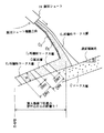
一般に図8に示す固体流れの模式断面図のように高炉1内に装入された鉱石とコークスは、鉱石層Oとコークス層Cとの層構造を保持した状態で鉱石の還元粉化を生じながら流れ線Aのようにシャフト内を降下する。すなわち高炉1内の炉周辺部領域3に装入されたコークスは羽口4から吹き込まれた熱風により形成されたレースウェイ6に向かって降下する。なお、炉頂より装入する高価なコークスを節減するために羽口4から熱風と共に微粉炭等の補助燃料を吹き込むことが盛んに行われている。
【0004】
そしてコークス等の装入物は羽口4前のレースウェイ6上部へのすりばち状の流れ込みと炉芯での荷下り停滞に代表される複雑な挙動で降下する。このようにして降下する装入物と上昇するガスとの各熱流速とのバランスによって融着帯5を形成し、滴下帯7を経由して炉床9に溶銑10とスラグ11がプールされる。炉床9にたまった溶銑10はスラグ11と共に出銑口8から炉外に排出される。
【0005】
ところで、前述のようにして鉱石とコークスとを交互に炉内に装入する際に、鉱石層の中にもコークスを混入して鉄鉱石の還元、溶融を促進するいわゆる混合装入技術(特開昭62−127413号公報)が知られている。鉄鉱石は高炉内で昇温、還元、軟化、溶融し、最終的に溶銑となって炉外に排出されるが、鉱石の軟化、収縮により層内を流れるガス量が低下すると還元が停滞し、同時に溶融、滴下が遅れるという問題が顕在化する。コークスを鉱石に混合する混合装入技術では、鉱石層内に分散して存在するコークスが鉱石の軟化、収縮を防止し、層内の通気性を改善している。前記の混合装入技術(特開昭62−127413号公報)では、炉内に形成される鉱石類層中に反応性指数:30%以上の高反応性コークスを全装入コークス量に対して30%を超えない範囲で存在させることを特徴としている。また、高反応性コークスは、鉱石層中に水平に層状に形成、あるいは鉱石層内に分散して存在している。
【0006】
また、ベルレス式高炉に鉄源の鉱石とコークスの混合原料を装入し、炉内に均一に分散させる方法としては、特開昭62−260010号公報が開示されている。混合原料中の還元剤の重量比率を一定、あるいは経時的に制御し、かつ、旋回シュートの傾動角度を制御して前記混合原料を炉中心部から炉壁方向に装入するとともに、炉内装入後の原料の堆積角度が20度を超えないように旋回シュートの傾動角度、各傾動角度における旋回数、下部ゲート弁開度のうち少なくとも1つを制御することを特徴とするベルレス式高炉の混合装入法である。このような制御を行うことによりコークスを鉱石層に均一に分散させることが可能であると報告されている。
【0007】
【発明が解決しようとする課題】
上記従来の混合装入技術は、微粉炭、重油等の補助燃料の吹き込み量が低く、炉頂から装入される鉱石(O)とコークス(C)の重量比(以後O/C)が比較的低い操業条件で効果を発揮してきた。一方、最近の微粉炭多量吹き込み(150kg/t 以上)でコークス比を350kg/t 以下(O/C 4.7以上)では混合装入を行っても充分な通気改善が得られないことが操業経験上明らかになってきた。
【0008】
鉱石中に混合されたコークスは、鉱石の収縮、変形に対する抵抗になるとともに、鉱石の還元により生じたCO2 を(1) 式の反応でCOに変えることにより鉱石の還元反応を促進している。
C+CO2 →2CO …………(1)
鉱石層に混合するコークスとして高反応性コークスを用いる理由は、(1) 式の反応を促進できることによる。
【0009】
微粉炭多量吹き込みでは、レースウエイ内で未燃焼となった微粉炭に由来するチャー粒子が、炉内をガスとともに上昇し、融着帯近傍で鉱石層、あるいは鉱石が軟化溶融した融着帯にトラップされる。未燃焼チャーは混合コークスと同様に(1) 式の反応により鉱石の還元に寄与すると同時にそれ自身が消費される。未燃焼のチャー反応性はコークスの反応性よりはるかに高いため、混合コークスが未反応となりその通気改善効果が充分現れない。また、微粉炭多量吹き込みでは装入原料のO/Cが増大し、相対的に鉱石層厚が増加している。その結果、鉱石層の通気が悪化し、特に鉱石の溶け落ち時の通気の悪化が問題になることが明らかになった。
【0010】
溶け落ち時には、鉱石層はほぼ完全に融着し、層内を流れるガス量は極端に少なくなる。鉱石を溶解するための熱量はその周辺のコークス層を流れるガスからの伝導伝熱により供給される。したがって、従来の混合装入による軟化融着帯の通気を多少改善したとても、その溶融を改善することは困難である。
以上、従来の混合装入法では上記に示した理由で充分な効果を発揮することが困難である。また、混合装入を実現するための装入法、特開昭60−260010号公報も層内での均一なコークスの分散を目的とする以上、その効果を充分に発揮することは困難である。
【0011】
【課題を解決するための手段】
鉱石の軟化、融着後の溶け落ちを支配するガス流れの変化、伝熱現象を詳細に検討したところ以下の点が明らかになった。
(1)融着帯内を流れるガスは極く微量であり、そのガス流れが伝熱溶解に及ぼす影響は小さい。
【0012】
(2)高O/C時の鉱石層の溶解の遅れは、厚い融着帯内での遅い伝導伝熱に起因している。したがって、鉱石層厚を薄くすることで溶解速度の向上を達成できる。
(3)融着帯内に縦方向に通気の良いコークススリットを縦方向に形成することにより融着帯内の伝熱を促進することができる。
【0013】
本発明は、とくに上記(3)に着目して高O/C時の鉱石層の溶解速度を向上させるものである。具体的には、鉱石層内に通気の良いコークス層を縦方向に筋状に形成することにより通気抵抗の小さいコークススリットを設け、そこを流れるガスにより溶解を促進する装入法とそれを実現するための具体的な装入手段に提供するものである。
【0014】
すなわち、請求項1記載の本発明は、高炉のベルレス装入装置に配置した炉頂ホッパから旋回シュートを介して炉内に鉱石とコークスとを交互に層状に装入する方法において、炉内に鉱石を装入する段階で、当該鉱石装入前に炉内に形成した炉周辺部から炉中心部に向け低くなる表面傾斜角度θが5度以上、25度以下のコークス層上に、炉頂ホッパから鉱石(O)とコークス(C)の一部とを混合させた状態で排出し、旋回シュートを流れる鉱石上にコークスを再偏析させつつ該シュートを炉中心部から周辺部に向けて傾動して装入することにより、炉内に装入された鉱石層に、縦方向にスリット状に形成される再偏析コークス層の炉半径方向の幅厚さDWf を装入レベルの炉口半径RO により無次元化した無次元再偏析コークス層幅厚さDWf /RO を0.01以上0.04以下として、炉半径方向に分布させることを特徴とするベルレス高炉における鉱石、コークス混合装入方法である。
【0015】
請求項2記載の本発明は、高炉のベルレス装入装置に配置した炉頂ホッパから旋回シュートを介して炉内に鉱石とコークスとを交互に層状に装入する方法において、炉内に鉱石を装入する段階で、当該鉱石装入前に炉内に形成した炉周辺部から炉中心部に向け低くなる表面傾斜角度θが5度未満のコークス層上に、炉頂ホッパから鉱石(O)とコークス(C)の一部とを混合させた状態で排出し、旋回シュートを流れる鉱石上にコークスを再偏析させつつ該シュートを炉中心部から周辺部に向けて傾動して原料落下位置間隔DRf を装入位置の炉口半径RO により無次元化した無次元原料落下位置間隔DRf /RO が下記条件式を満足するように装入し、炉内装入された鉱石層に、縦方向にスリット状に形成される再偏析コークス層の炉半径方向の幅厚さDWf を装入レベルの炉口半径RO により無次元化した無次元再偏析コークス層幅厚さDWf /RO を0.005 以上0.01未満として炉半径方向に分布させることを特徴とするベルレス高炉における鉱石、コークス混合装入方法である。
【0016】
記
無次元原料落下位置間隔DRf /R O >0.04−0.008 ×(鉱石装入前に形成したコークス層の表面傾斜角度)
請求項3記載の本発明は、炉内に装入した鉱石層に、縦方向にスリット状に形成される再偏析コークス層を炉半径方向に3箇所以上に分布させることを特徴とする請求項1または請求項2のベルレス高炉における鉱石、コークス混合装入方法である。
【0017】
【作用】
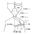
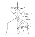
図5にベルレス高炉1での鉱石とコークスとの混合原料の装入方法を示す。地上に設置された(図示しない)鉱石槽、コークス槽から装入ベルトコンベヤを用いて2基のうちの一方の炉頂ポッパ12に原料として鉱石(O)とコークス(C)とを装入し、炉頂ホッパ12から鉱石(O)、コークス(C)を同時に排出することにより混合装入を行う。混合装入を行う手段としては、図示したように鉱石、コークスを同一のホッパ12に積み付け排出し、上下2層または多層に積み付ける方法、あるいは図6に示したように鉱石(O)とコークス(C)を炉頂の別々のホッパ12に貯蔵し、同時に排出することによって混合装入する方法などが考えられるが、特に限定する必要はなく、炉頂ホッパ12に原料を装入する以前に予め鉱石とコークスを混合しておいてもよい。炉頂ホッパ12から排出された鉱石(O)、コークス(C)は集合シュート13を経由して所定の角度を保ちながら回転する旋回シュート14にて炉頂部15に積み付けられる。装入物は炉内で旋回毎に積み付けられ、最終的に鉱石層O、コークス層Cを形成する。なお、図5、図6におけるC1 は、鉱石層O内に形成されるスリット状の再偏析コークス層を示している。
【0018】
混合装入時における旋回シュート14から排出される原料の挙動を図1〜図4に示した。旋回シュート14上で小粒径で重い鉱石層O2 はシュート底面をゆっくりと流れ、大粒径で軽いコークス層C1 は中、大粒径の鉱石層O1 の上面部を速いスピードで流れる。その結果、コークスがより遠くへ落下する再偏析コークス層C1 が現れる。この状態で旋回シュートの傾動角度の変更方向、変更の大きさ、下面の形状を種々変更してコークスの堆積挙動を調べた結果が図1〜図4である。図4に示すように、旋回シュート14の傾動角度を通常行われている矢印で示す傾動方向、すなわち炉周辺部から炉中心部へ変更した場合には炉壁に再偏析したコークスC1 が装入されたのち中心部へ押し流されて再度炉中心部へ堆積するため、鉱石層内にスリット状の縦方向に偏析したコークススリットを形成できず、炉中心部に再偏析コークス層C1 を形成する。一方、炉中心部から炉周辺部に向けて逆方向に旋回シュートの傾動角を変更し、下層のコークス層Cの表面傾斜角、旋回シュートの傾動角の変化幅を適正に設定すると図1のように鉱石層Oにスリット状(筋状)に本発明の再偏析コークス層C1 が入った鉱石層Oを形成することができる。
【0019】
図2のように下層のコークス層Cの表面傾斜が緩く、かつ旋回シュート14を炉周辺部から炉中心部へ変更すると前回旋回時の装入位置と今回の装入位置が接近している場合には、前回旋回時の再偏析コークス層C0 が装入物の落下流により炉壁方向に押し流され、図1のように適正な再偏析コークス層C1 を形成することが困難になる。このため、各旋回毎の再偏析コークス層が押し流されて集まり、炉壁部にコークス単一層を形成する。一方、図3に示すように下層のコークス層Cの表面傾斜がきつい場合には、各旋回で装入された原料は装入位置に留まらず、中心部に流れ込んで再偏析コークス層C1 を形成するため、適正な再偏析コークス層が得られない。
【0020】
本発明では、図1に示すように、旋回シュート14を炉中心部から炉周辺部に向けて傾動角を変更すると共に、下層のコークス層Cの表面傾斜角θを適正にすることによって鉱石層Oにスリット状の再偏析コークス層C1 を炉半径方向に環状に分布させることができる。
図1では、鉱石を装入する前のコークス層Cの表面傾斜角θ、炉中心から原料落下位置までの距離Rf において、旋回シュート14から旋回ごとにコークス層C上に形成される炉半径方向の鉱石とコークスとを含む原料落下位置間隔DRf および縦方向にスリット状の再偏析コークス層C1 の幅厚さをDWf としている。このような原料落下位置間隔DRf を落下位置での炉口半径RO で無次元化した無次元原料落下位置間隔DRf /RO および再偏析コークス層C1 の幅厚さDWf を同じく炉口半径RO で無次元化した無次元再偏析コークス層幅厚さDWf /RO と定義する。
【0021】
図1に示すような通気を向上させるのに最適なスリット状の再偏析コークス層C1 を鉱石層Oに形成させる条件を調査した。すなわち鉱石装入前の下層のコークス層Cが炉周辺部から炉中心部に向け低くなる表面傾斜角θを、無次元原料落下位置間隔DRf /RO と、鉱石層Oに形成される無次元再偏析コークス層幅厚さDWf /RO とにより評価した。その結果を図7に示す。図7における○印は鉱石層Oに縦方向にスリット状の十分な無次元再偏析コークス層幅厚さDWf /RO =0.01〜0.04が形成される場合、△は許容できるDWf /RO =0.005 〜0.01未満が形成される場合、また●印は再偏析コークス層の形成が不十分なDWf <0.005 の場合を示している。
【0022】
図7に示すように鉱石装入前のコークス層Cの表面傾斜角θが5度以上、25度以下で十分または許容し得る無次元再偏析コークス層幅厚さが得られることがわかる。また、鉱石装入前のコークス層Cの表面傾斜角θが5度未満では無次元原料落下位置間隔DRf /RO =0.04と傾斜角θ=5度を結んだ直線より上の領域、つまり無次元原料落下位置間隔DRf /R O >0.04−0.008 ×(鉱石装入前に形成したコークス層の表面傾斜角度)で少なくとも許容できるDWf /RO =0.005 〜0.01未満が得られることを示している。
【0023】
一方、無次元原料落下位置間隔DRf /RO =0.04と鉱石装入前のコークス層Cの表面傾斜角θ=5度を結んだ線より下方の領域では、炉周辺部へのコークス流れ込みにより、いずれも無次元再偏析コークス層幅厚さDWf /RO <0.005 となり鉱石層O内に適正な再偏析コークス層C1 をほとんど形成せず、通気の向上に寄与しない。
【0024】
このような鉱石層Oに形成される再偏析コークス層C1 は、必ずしも旋回シュート14の各旋回ごとに形成する必要はなく、鉱石層Oの溶融が不十分になると考えられる部位を中心とする特定領域の半径方向に3箇所以上、望ましくは6箇所以上に分布するように形成するのが好適である。通常時に旋回シュート14からコークス層C上に装入される鉱石層Oの平均層厚H(図1参照)は炉口半径RO で無次元化した無次元鉱石層厚H/RO =0.1 であるので、原料落下位置炉口半径RO =540cm の場合には、平均鉱石層厚H=RO ×0.1 =54cmとなる。
【0025】
鉱石層Oの溶融が不十分となる半径方向部位、無次元距離0.3 の領域の鉱石溶融性改善するには、無次元鉱石層厚H=54cmよりも小さい位置間隔DRf <H(=54cm)でコークス再偏析層C1 を形成する必要がある。すなわち、無次元距離0.3 に相当する半径方向の領域=540cm ×0.3 =162cm に旋回シュート14から(162 /54=3)3回の旋回により少なくとも3箇所の再偏析コークス層C1 を形成することが必要になる。さらに、伝熱溶融速度を改善するには、6箇所以上の再偏析コークス層C1 を形成するのが望ましい。
【0026】
なお、再偏析コークス層C1 を鉱石層Oの半径方向における特定領域に形成するには、たとえば、図6に示すように2基の炉頂ホッパ12にそれぞれ収容した鉱石(O)とコークス(C)とを排出するタイミングを制御することにより可能となる。すなわち、まず炉頂ホッパ12から鉱石(O)を排出し、旋回シュート14が特定領域に達する時点で別の炉頂ホッパ12からコークス(C)を排出すればよい。
【0027】
【実施例】
本発明の混合装入法を内容積4500m3 ,炉口径: 5.3mの大型ベルレス高炉で実施した結果を表1に示した。炉頂に2個の並列バンカーを有する高炉であり、シュート長 4.0mの旋回シュートを用いて、1バッチの鉱石、コークスを13旋回にて炉内に装入している。旋回シュートの傾動角度の設定は、52.5度を1ポイント、13度を14ポイントとし、その間を等間隔で分割したポイントを用いて行った。燃料比は480kg/t から510kg/t の間にあり、微粉炭多量吹き込みを実施している。混合装入コークスとして粒径15−50mmの通常コークスとほぼ同じ粒径のコークスを約80kg/t装入した。鉱石を炉頂ホッパーに装入し、その後同一のホッパーに混合用コークスを装入し、同時に排出した。
【0028】
【表1】

比較例1では炉壁部に傾斜角が0のコークス表面(コークステラス)を形成し、そのうえに混合コークス層を形成させた。コークステラスの長さが1.5 mと短いため、混合装入時の無次元原料落下位置間隔は0.03と短い。その結果、炉壁近傍に混合コークスが集中して堆積し、鉱石層に縦方向に筋状のコークス層を形成することが困難になっている。その結果、高炉下部の圧力損失が0.029kg/m3と大きく、かつ通気抵抗の変動σΔP/vが0.030 と操業の変動が大きいことが分かる。溶銑温度を1500℃以上に維持することが困難になり同時に、溶銑中の[Si]の変動も著しく大きい。
【0030】
比較例2では炉壁部のコークステラスの長さを0.5 mと短くし、混合原料をコークスの斜面(角度26度)上に装入した。混合装入時の無次元原料落下位置間隔は0.05と大きいものの、装入された混合原料は炉壁近傍の装入位置に留まらず、炉中心部に流れ込む。同時に、混合原料中のコークスが炉内で再偏析を起こし、炉中心部に混合コークスが集中して堆積した。その結果、高炉下部の圧力損失が0.030kg/m3と大きく、かつ通気抵抗の変動σΔP/vが0.028 と安定な操業ができていないことがわかる。また、溶銑温度を1500℃以上に維持することが困難になると同時に、炉頂のガスの利用率が低下し、燃料比を520kg/t にまで上昇することを余儀なくされている。
【0031】
実施例1では、炉壁部に傾斜角が5度のコークス表面(コークステラス)を形成し、そのうえに混合コークス層を形成させた。コークステラスの長さを2.5 mと長くしたため、混合装入時の無次元原料落下位置間隔は0.04と大きくとることが可能になった。その結果、炉壁近傍に装入した混合原料は図1に示すように、鉱石層内の縦方向にスリット状の再偏析コークス層C1 を形成している。その結果、軟化、融着帯の溶解が促進され、結果、高炉下部の圧力損失が0.020kg/m3に低下し、かつ通気抵抗の変動σΔP/vが0.018 まで低下、安定操業が実現できた。溶銑温度を1503℃と高めに維持することが可能になり、微粉炭吹き込み量を200kg/t まで増加、同時に燃料比を490kg/t に低下できた。
【0032】
実施例2では、炉壁部のコークステラスの長さを0.5 mと短くし、混合原料をコークスの斜面(角度15度)上に装入した。混合装入時の無次元原料落下位置間隔は0.05と大きくし、同時に、下面の傾斜角を20度になるようにコークスの装入パターンを調整した。コークスの傾斜角が適正範囲のため、装入された混合原料は装入位置に留まり、図1に示すような安定な堆積層を形成した。その結果、高炉下部の圧力損失は0.018kg/m3まで低下し、かつ通気抵抗の変動σΔP/vが0.015 と安定操業が可能になった。同時に、溶銑温度を1505℃と高めに維持することが可能になり、微粉炭吹き込み量を205kg/t まで増加、同時に燃料比を480kg/t に低下できた。
【0033】
本実施例では、鉱石を炉頂ホッパーに装入し、その後同一のホッパーに混合コークスを装入し、同時に排出したが、混合コークスを異なるホッパーに装入し鉱石と同時に排出することも可能である。また、混合コークスとして通常コークスに近い通気性の良いコークスを用いたが、従来から行われているように高反応性の小粒径のコークスを用いることも可能である。
【0034】
【発明の効果】
以上説明したように本発明ではコークスの生産能力の低下時、コークス不足時の低コークス比操業時、微粉炭多量吹き込み操業時において、高炉内に装入した鉱石の溶解速度を再偏析コークス層の通気改善効果を利用して上昇することにより、コークス比の一層の低下、操業の安定を達成することができる。
【0035】
製鉄所内のコークス生産量が不足する場合には、一般には市場からコークスを購入し補うことが一般的であるが、市場コークスの値段は自家生産コークスの約50%増しであり、コークス使用量を減少できる本発明の経済的効果は大きい。また、通気性の改善により、実施例でも示したように出銑量が増加、製鉄所全体の生産量を増加できる。
【図面の簡単な説明】
【図1】本発明例の原料装入により鉱石層に適正な再偏析コークス層が形成される場合を断面で示す説明図である。
【図2】比較例1の原料装入により適正な再偏析コークス層が形成されない場合を断面で示す説明図である。
【図3】比較例2の原料装入により適正な再偏析コークス層が形成されない場合を断面で示す説明図である。
【図4】従来例の原料装入により適正な再偏析コークス層が形成されない場合を断面で示す説明図である。
【図5】本発明に係る同一の炉頂ホッパから鉱石、コークスを同時に排出し、旋回シュートを介して装入する場合を断面で示す説明図である。
【図6】本発明に係る別々の炉頂ホッパから鉱石、コークスを同時に排出し、旋回シュートを介して装入する場合を断面で示す説明図である。
【図7】鉱石装入前の下層のコークス層が炉周辺部から炉中心部に向け低くなる表面傾斜角θと無次元原料落下位置間隔DRf /RO との関係を、鉱石層に形成される無次元再偏析コークス層幅厚さDWf /RO より評価したグラフである。
【図8】従来の高炉内原料の効果状況を断面で模式的に示す説明図である。
【符号の説明】
1 高炉(ベルレス高炉)
2 炉中心部領域
3 炉周辺部領域
4 羽口
5 融着帯
6 レースウェイ
7 滴下帯
8 出銑口
9 炉床
10 溶銑
11 スラグ
12 炉頂ホッパ
13 集合シュート
14 旋回シュート
15 炉頂部
A 流れ線
C コークス層
O 鉱石層[0001]
[Industrial applications]
TECHNICAL FIELD The present invention relates to a method for charging ore and coke alternately in layers from a furnace top hopper arranged in a blast furnace bellless charging device into a furnace through a swirling chute.
[0002]
[Prior art]
The raw material charging equipment for blast furnaces can be roughly classified into bell-type charging equipment, a furnace-less hopper, and a bell-less charging equipment with a rotating chute.In recent years, bell-less charging equipment, which has a high degree of freedom in charging method, has become mainstream. It is becoming. In the bellless type charging apparatus, the raw material charged in the furnace top hopper can be charged into an arbitrary position in the radial direction of the blast furnace by using a turning chute. In normal charging, ore, which is an iron raw material, fuel and coke, which is a reducing agent, are alternately charged into a furnace, and an ore layer and a coke layer are alternately formed in the furnace.
[0003]
Generally, ore and coke charged in the blast furnace 1 as shown in the schematic cross-sectional view of the solid flow shown in FIG. 8 cause reduction oreization of the ore while maintaining the layer structure of the ore layer O and the coke layer C. While descending in the shaft as indicated by the flow line A. That is, the coke charged in the furnace
[0004]
The charge such as coke descends in a complicated manner typified by a slash-like flow into the upper part of the
[0005]
By the way, when ore and coke are alternately charged into the furnace as described above, so-called mixed charging technology (special feature) in which coke is mixed into the ore layer to promote reduction and melting of iron ore. Japanese Unexamined Patent Publication No. 62-127413) is known. Iron ore is heated, reduced, softened, and melted in the blast furnace, and eventually becomes hot metal and discharged out of the furnace.However, if the amount of gas flowing through the bed decreases due to softening or shrinking of the ore, the reduction stagnates At the same time, the problem of delay in melting and dropping becomes apparent. In the mixed charging technique of mixing coke with ore, coke dispersed in the ore layer prevents softening and shrinkage of the ore, and improves air permeability in the layer. In the mixed charging technique (Japanese Patent Application Laid-Open No. 62-127413), a highly reactive coke having a reactivity index of 30% or more is contained in an ore layer formed in a furnace with respect to the total charged coke amount. It is characterized by being present in a range not exceeding 30%. The highly reactive coke is formed in the ore layer horizontally and in a layered form or is dispersed in the ore layer.
[0006]
Japanese Patent Application Laid-Open No. Sho 62-260010 discloses a method in which a mixed raw material of iron ore and coke is charged into a bellless blast furnace and uniformly dispersed in the furnace. The weight ratio of the reducing agent in the mixed raw material is controlled constant or with time, and the tilt angle of the swirling chute is controlled to load the mixed raw material from the center of the furnace toward the furnace wall, Mixing at least one of the tilt angle of the rotary chute, the number of turns at each tilt angle, and the opening degree of the lower gate valve so that the deposition angle of the raw material does not exceed 20 degrees. It is a charging method. It is reported that by performing such control, coke can be uniformly dispersed in the ore layer.
[0007]
[Problems to be solved by the invention]
In the conventional mixed charging technology, the amount of auxiliary fuel such as pulverized coal and heavy oil injected is low, and the weight ratio of ore (O) and coke (C) charged from the furnace top (hereinafter O / C) is compared. It has been effective under extremely low operating conditions. On the other hand, if the coke ratio is 350 kg / t or less (O / C 4.7 or more) with recent pulverized coal injection (150 kg / t or more), sufficient ventilation improvement cannot be obtained even with mixed charging. It has become clear from experience.
[0008]
The coke mixed in the ore is not only resistant to shrinkage and deformation of the ore, but also promotes the reduction reaction of the ore by converting CO 2 generated by the reduction of the ore into CO by the reaction of the formula (1). .
C + CO 2 → 2CO (1)
The reason why highly reactive coke is used as coke mixed in the ore layer is that the reaction of the formula (1) can be promoted.
[0009]
In the pulverized coal injection, char particles derived from unburned pulverized coal in the raceway rise together with the gas in the furnace, and enter the ore layer or the cohesive zone where the ore softens and melts near the cohesive zone. Be trapped. The unburned char contributes to the reduction of the ore by the reaction of the formula (1) as well as the mixed coke and is consumed by itself. Since the reactivity of unburned char is much higher than the reactivity of coke, the mixed coke becomes unreacted and the effect of improving the ventilation is not sufficiently exhibited. In addition, when a large amount of pulverized coal is blown, the O / C of the charged material increases, and the ore layer thickness relatively increases. As a result, it became clear that the ventilation of the ore layer deteriorated, and the deterioration of the ventilation when the ore melted off became a problem.
[0010]
At the time of burn-through, the ore layer is almost completely fused and the amount of gas flowing through the layer becomes extremely small. The amount of heat for dissolving the ore is supplied by conduction heat transfer from the gas flowing in the surrounding coke layer. Therefore, it is very difficult to improve the melting of the softened cohesive zone, which is somewhat improved by the conventional mixed charging.
As described above, it is difficult for the conventional mixed charging method to exhibit a sufficient effect for the reasons described above. Also, the charging method for realizing the mixed charging, Japanese Patent Application Laid-Open No. 60-260010, aims at uniformly dispersing the coke in the layer, and it is difficult to sufficiently exhibit the effect. .
[0011]
[Means for Solving the Problems]
A detailed examination of the changes in gas flow and heat transfer phenomena that govern ore softening, burn through after fusion, and the following points were clarified.
(1) The amount of gas flowing in the cohesive zone is extremely small, and the influence of the gas flow on heat transfer melting is small.
[0012]
(2) The delay in dissolution of the ore layer at high O / C is due to slow conduction heat transfer in the thick cohesive zone. Therefore, the dissolution rate can be improved by reducing the thickness of the ore layer.
(3) The heat transfer in the cohesive zone can be promoted by forming a coke slit with good ventilation in the longitudinal direction in the cohesive zone in the longitudinal direction.
[0013]
The present invention aims to improve the dissolution rate of the ore layer at a high O / C time, particularly focusing on the above (3). Specifically, a coke slit with low airflow resistance is provided by forming a well-ventilated coke layer in the ore layer in a streak shape in the vertical direction, and the charging method that promotes dissolution by the gas flowing there and realizes it. To provide specific charging means.
[0014]
That is, the present invention according to claim 1 is a method for charging ore and coke alternately in layers from a furnace top hopper disposed in a bellless charging device of a blast furnace via a swirling chute into a furnace. At the stage of charging the ore, the furnace top is placed on a coke layer having a surface inclination angle θ decreasing from the furnace peripheral portion formed in the furnace before the ore charging toward the furnace central portion of 5 ° or more and 25 ° or less. The ore (O) and a part of the coke (C) are discharged from the hopper in a mixed state, and the chute is tilted from the furnace center toward the periphery while resegregating the coke on the ore flowing through the swirling chute. In the ore layer charged in the furnace, the width DW f of the re-segregated coke layer formed in the longitudinal slit shape in the furnace radial direction is set to the charging port radius at the charging level. dimensionless re segregation coke layer width dimensionless by R O thickness DW f This is a method for charging ore and coke in a bellless blast furnace, wherein / R O is set to 0.01 to 0.04 and distributed in the furnace radial direction.
[0015]
The present invention is claimed in
[0016]
Dimensionless raw material drop position interval DR f / R O > 0.04-0.008 × (surface inclination angle of coke layer formed before ore charging)
According to a third aspect of the present invention, in the ore layer charged in the furnace, a re-segregated coke layer formed in a longitudinally slit shape is distributed at three or more locations in the furnace radial direction. A method for charging ore and coke in a bellless blast furnace according to
[0017]
[Action]
FIG. 5 shows a method of charging a mixed raw material of ore and coke in the bellless blast furnace 1. Ore (O) and coke (C) are charged as raw materials into one of the two furnace top poppers 12 from a ore tank and a coke tank (not shown) installed on the ground using a charging belt conveyor. The ore (O) and the coke (C) are simultaneously discharged from the furnace top hopper 12 to perform mixed charging. As a means for carrying out the mixed charging, a method of stacking ore and coke in the same hopper 12 as shown in the figure and discharging and stacking the ore and coke in two layers, upper and lower layers, or ore (O) as shown in FIG. A method in which coke (C) is stored in separate hoppers 12 at the furnace top and mixed and charged by discharging simultaneously is conceivable, but there is no particular limitation. Ore and coke may be mixed in advance. The ore (O) and the coke (C) discharged from the furnace top hopper 12 are stacked on the
[0018]
The behavior of the raw material discharged from the swirling
[0019]
As shown in FIG. 2, when the lower coke layer C has a gentle surface inclination and the swirling
[0020]
In the present invention, as shown in FIG. 1, the ore layer is formed by changing the tilt angle of the turning
In FIG. 1, at the surface inclination angle θ of the coke layer C before the ore is charged and the distance Rf from the furnace center to the raw material falling position, the furnace radius formed on the coke layer C from the swirling
[0021]
The optimal slit re segregation coke layer C 1 to improve ventilation, such as shown in FIG. 1 was investigated conditions for forming the ore layer O. That is, the surface inclination angle θ at which the lower coke layer C lowers from the furnace periphery toward the furnace center before the ore charging is determined by the dimensionless raw material drop position interval DR f / RO and the non-formation formed in the ore layer O. It was evaluated by the dimension re segregation coke layer width thickness DW f / R O. FIG. 7 shows the result. In FIG. 7, the circles in FIG. 7 indicate that when the ore layer O has a sufficient dimensionless resegregated coke layer width DW f / R O = 0.01 to 0.04 in the form of a slit in the longitudinal direction, Δ is acceptable. DW f / R O = 0.005 to less than 0.01 is formed, and the mark ● indicates the case where DW f <0.005 where formation of the re-segregated coke layer is insufficient.
[0022]
As shown in FIG. 7, it is found that a sufficient or acceptable dimensionless re-segregation coke layer width thickness is obtained when the surface inclination angle θ of the coke layer C before ore charging is 5 degrees or more and 25 degrees or less. If the surface inclination angle θ of the coke layer C before the ore charging is less than 5 degrees, the area above the straight line connecting the dimensionless raw material drop position interval DR f / R O = 0.04 and the inclination angle θ = 5 degrees, that is, that at least tolerable than DW f / R O = 0.005 ~0.01 dimensionless material falling position distance DR f / R O> 0.04-0.008 × ( surface inclination angle of the coke layer formed before ore loading) is obtained Is shown.
[0023]
On the other hand, in the area below the line connecting the dimensionless raw material drop position interval DR f / R O = 0.04 and the surface inclination angle θ = 5 degrees of the coke layer C before charging the ore, the coke Due to the pouring, the dimensionless re-segregated coke layer width becomes DW f / R O <0.005, and almost no appropriate re-segregated coke layer C 1 is formed in the ore layer O, and does not contribute to the improvement of ventilation.
[0024]
Re segregation coke layer C 1, which is formed in such ores layer O is not necessarily formed for each turn of the
[0025]
In order to improve the ore fusibility in the radial area where the ore layer O is insufficiently melted and in the area with a dimensionless distance of 0.3, the position interval DR f <H (= smaller than the dimensionless ore layer thickness H = 54 cm) 54cm) it is necessary to form a coke re segregation layer C 1 at. That is, at least three re-segregated coke layers C 1 by turning (162/54 = 3) three times from the turning
[0026]
Incidentally, the re-segregation coke layer C 1 to form a specific area in the radial direction of the ore layer O is, for example, ore containing respectively furnace top hopper 12 of 2 groups as shown in FIG. 6 (O) and coke ( C) can be achieved by controlling the timing of discharging That is, the ore (O) is first discharged from the furnace top hopper 12, and the coke (C) may be discharged from another furnace hopper 12 when the turning
[0027]
【Example】
Table 1 shows the results obtained when the mixed charging method of the present invention was carried out in a large bellless blast furnace having an inner volume of 4,500 m 3 and a furnace diameter of 5.3 m. This is a blast furnace having two parallel bunkers on the furnace top, and a batch of ore and coke are charged into the furnace at 13 turns using a 4.0 m swivel chute. The tilt angle of the turning chute was set using 52.5 degrees as one point and 13 degrees as 14 points, and using points divided at regular intervals. The fuel ratio is between 480 kg / t and 510 kg / t, and a large amount of pulverized coal is injected. About 80 kg / t of coke having substantially the same particle size as normal coke having a particle size of 15 to 50 mm was charged as mixed charging coke. The ore was charged into the top hopper, and then the same hopper was charged with coke for mixing and simultaneously discharged.
[0028]
[Table 1]
In Comparative Example 1, a coke surface (coke terrace) having an inclination angle of 0 was formed on the furnace wall, and a mixed coke layer was formed thereon. Since the length of the coke terrace is as short as 1.5 m, the distance between the non-dimensional raw material falling positions during mixing and charging is as short as 0.03. As a result, mixed coke is concentrated and deposited in the vicinity of the furnace wall, and it is difficult to form a vertical coke layer in the ore layer. As a result, it can be seen that the pressure loss in the lower part of the blast furnace was as large as 0.029 kg / m 3 , and the variation σΔP / v of the ventilation resistance was as large as 0.030, indicating a large variation in operation. It becomes difficult to maintain the hot metal temperature at 1500 ° C. or higher, and at the same time, the variation of [Si] in the hot metal is remarkably large.
[0030]
In Comparative Example 2, the length of the coke terrace on the furnace wall was shortened to 0.5 m, and the mixed material was charged on the slope (angle 26 degrees) of the coke. Although the dimensionless material falling position interval at the time of mixing and charging is as large as 0.05, the charged mixed material does not stay at the charging position near the furnace wall but flows into the furnace center. At the same time, the coke in the mixed raw material re-segregated in the furnace, and the mixed coke was concentrated and deposited at the center of the furnace. As a result, it can be seen that the pressure loss in the lower part of the blast furnace was as large as 0.030 kg / m 3 , and that the fluctuation σΔP / v of the ventilation resistance was 0.028, indicating that stable operation was not possible. Further, it becomes difficult to maintain the hot metal temperature at 1500 ° C. or higher, and at the same time, the utilization rate of the gas at the furnace top decreases, and the fuel ratio is forced to increase to 520 kg /
[0031]
In Example 1, a coke surface (coke terrace) having an inclination angle of 5 degrees was formed on the furnace wall, and a mixed coke layer was formed thereon. Since the length of the coke terrace has been increased to 2.5 m, the distance between the non-dimensional raw materials at the time of mixing and charging can be as large as 0.04. As a result, the mixed material was charged in the vicinity of the furnace wall, as shown in FIG. 1, to form a slit-shaped re-segregation coke layer C 1 in the vertical direction in the ore layer. As a result, softening and melting of the cohesive zone are promoted, and as a result, the pressure loss in the lower part of the blast furnace is reduced to 0.020 kg / m 3 , and the variation σΔP / v of the ventilation resistance is reduced to 0.018, and stable operation is achieved. It was realized. It became possible to maintain the hot metal temperature as high as 1503 ° C., and it was possible to increase the pulverized coal injection amount to 200 kg / t, and at the same time, reduce the fuel ratio to 490 kg / t.
[0032]
In Example 2, the length of the coke terrace on the furnace wall was reduced to 0.5 m, and the mixed raw material was charged on the slope (angle of 15 degrees) of the coke. The non-dimensional raw material drop position interval at the time of mixing charging was increased to 0.05, and at the same time, the charging pattern of coke was adjusted so that the inclination angle of the lower surface became 20 degrees. Since the inclination angle of the coke was within the proper range, the charged mixed raw material stayed at the charging position and formed a stable deposited layer as shown in FIG. As a result, the pressure loss in the lower part of the blast furnace was reduced to 0.018 kg / m 3 , and the fluctuation σΔP / v of the ventilation resistance was 0.015, which enabled stable operation. At the same time, the hot metal temperature could be maintained as high as 1505 ° C., and the pulverized coal injection amount could be increased to 205 kg / t, and at the same time, the fuel ratio could be reduced to 480 kg / t.
[0033]
In the present embodiment, the ore is charged into the furnace top hopper, and then the mixed coke is charged into the same hopper and discharged simultaneously.However, the mixed coke can be charged into a different hopper and discharged simultaneously with the ore. is there. Further, although coke having good air permeability close to that of ordinary coke is used as mixed coke, coke of small particle diameter having high reactivity as conventionally used can be used.
[0034]
【The invention's effect】
As described above, in the present invention, when the production capacity of coke is reduced, when the coke ratio is low when the coke is insufficient, and when the pulverized coal is blown in a large amount, the dissolution rate of the ore charged in the blast furnace is adjusted by the re-segregation coke layer. By ascending using the effect of improving the ventilation, the coke ratio can be further reduced and the operation can be stabilized.
[0035]
When the production of coke in a steelworks is insufficient, it is common to purchase coke from the market and supplement it. However, the price of coke in the market is about 50% higher than that of self-produced coke. The economic effect of the present invention that can be reduced is great. Further, by improving the air permeability, the tapping amount can be increased as shown in the embodiment, and the production amount of the entire steelworks can be increased.
[Brief description of the drawings]
FIG. 1 is an explanatory view showing a cross section of a case where an appropriate re-segregation coke layer is formed in an ore layer by charging raw materials according to the present invention.
FIG. 2 is an explanatory view showing a cross section of a case where an appropriate re-segregation coke layer is not formed by charging the raw material in Comparative Example 1.
FIG. 3 is an explanatory view showing a cross section of a case where an appropriate re-segregation coke layer is not formed by charging the raw material in Comparative Example 2.
FIG. 4 is an explanatory view showing a cross section of a conventional example in which a proper resegregation coke layer is not formed by charging raw materials.
FIG. 5 is an explanatory view showing a cross section of a case where ore and coke are simultaneously discharged from the same furnace hopper according to the present invention and charged via a swirling chute.
FIG. 6 is an explanatory view showing a cross section of a case where ore and coke are simultaneously discharged from separate furnace hoppers according to the present invention and charged via a swirling chute.
[7] coke layer under the previous ore charging is the relationship between the lower becomes the surface tilt angle θ and dimensionless material falling position distance DR f / R O toward the furnace central portion from the furnace peripheral portion, formed in the ore layer is a graph showing an evaluation from dimensionless re segregation coke layer width thickness DW f / R O being.
FIG. 8 is an explanatory view schematically showing the effect of conventional blast furnace raw materials in cross section.
[Explanation of symbols]
1 Blast furnace (bellless blast furnace)
2 Furnace
Claims (3)
記
無次元原料落下位置間隔DRf /R O >0.04−0.008 ×(鉱石装入前に形成したコークス層の表面傾斜角度)In a method in which ore and coke are charged alternately into a furnace through a swirling chute from a furnace top hopper arranged in a bellless charging device of a blast furnace, in the step of charging the ore into the furnace, the ore loading is performed. The ore (O) and a part of coke (C) from the furnace top hopper are placed on a coke layer having a surface inclination angle θ of less than 5 degrees, which decreases from the furnace periphery to the furnace center formed in the furnace before entering. Is discharged in a mixed state, and while the coke is re-segregated on the ore flowing through the swirling chute, the chute is tilted from the furnace center toward the periphery to set the raw material drop position interval DR f to the furnace port at the charging position. The non-dimensional raw material drop position interval DR f / R O made dimensionless by the radius R O is charged so as to satisfy the following conditional expression, and is formed into a longitudinally slit shape in the ore layer placed inside the furnace. The width of the resegregated coke layer in the furnace radial direction DW f Ore and coke mixing in a bellless blast furnace characterized in that the dimensionless resegregated coke layer width DW f / R O dimensionlessized by the furnace opening radius R O is distributed in the furnace radial direction with the thickness DW f / R O being 0.005 or more and less than 0.01. How to charge.
Non-dimensional raw material drop position interval DR f / R O > 0.04-0.008 × (surface inclination angle of coke layer formed before ore charging)
Priority Applications (1)
| Application Number | Priority Date | Filing Date | Title |
|---|---|---|---|
| JP28207695A JP3588877B2 (en) | 1995-10-30 | 1995-10-30 | Ore and coke charging method in bellless blast furnace |
Applications Claiming Priority (1)
| Application Number | Priority Date | Filing Date | Title |
|---|---|---|---|
| JP28207695A JP3588877B2 (en) | 1995-10-30 | 1995-10-30 | Ore and coke charging method in bellless blast furnace |
Publications (2)
| Publication Number | Publication Date |
|---|---|
| JPH09125112A JPH09125112A (en) | 1997-05-13 |
| JP3588877B2 true JP3588877B2 (en) | 2004-11-17 |
Family
ID=17647821
Family Applications (1)
| Application Number | Title | Priority Date | Filing Date |
|---|---|---|---|
| JP28207695A Expired - Fee Related JP3588877B2 (en) | 1995-10-30 | 1995-10-30 | Ore and coke charging method in bellless blast furnace |
Country Status (1)
| Country | Link |
|---|---|
| JP (1) | JP3588877B2 (en) |
Families Citing this family (4)
| Publication number | Priority date | Publication date | Assignee | Title |
|---|---|---|---|---|
| KR20030052726A (en) * | 2001-12-21 | 2003-06-27 | 주식회사 포스코 | Method for charging of mixture of nut coke and ore |
| JP5135959B2 (en) * | 2007-09-06 | 2013-02-06 | Jfeスチール株式会社 | Raw material charging method and raw material charging apparatus for blast furnace |
| JP5581897B2 (en) * | 2009-12-02 | 2014-09-03 | Jfeスチール株式会社 | Blast furnace operation method |
| JP5861392B2 (en) * | 2011-11-01 | 2016-02-16 | Jfeスチール株式会社 | Blast furnace operation method |
-
1995
- 1995-10-30 JP JP28207695A patent/JP3588877B2/en not_active Expired - Fee Related
Also Published As
| Publication number | Publication date |
|---|---|
| JPH09125112A (en) | 1997-05-13 |
Similar Documents
| Publication | Publication Date | Title |
|---|---|---|
| RU2202625C2 (en) | Method of production of molten metallic iron (versions) | |
| AU776002B2 (en) | Method and facilities for metal smelting | |
| BG60921B2 (en) | Method and device for continuous steel casting | |
| JP5696814B2 (en) | Raw material charging method for bell-less blast furnace | |
| JP3588877B2 (en) | Ore and coke charging method in bellless blast furnace | |
| CN1033529A (en) | The method of continuous smelting iron and steel scrap and equipment thereof | |
| JP3573780B2 (en) | Raw material charging method for bellless blast furnace | |
| JP2002003910A (en) | Method for operating blast furnace | |
| JP3700457B2 (en) | Blast furnace operation method | |
| JP3700458B2 (en) | Low Si hot metal manufacturing method | |
| KR100376480B1 (en) | Burden distribution control method in blast furnace by using coke | |
| JP6950718B2 (en) | How to charge raw materials for Bellless blast furnace | |
| KR20030052726A (en) | Method for charging of mixture of nut coke and ore | |
| JPH11217605A (en) | Method for charging charging material into blast furnace | |
| JPH06271908A (en) | Method for charging raw material in multi-batches into bell-less blast furnace | |
| JP3031203B2 (en) | Hot metal production method | |
| JPS5941402A (en) | Operation of blast furnace | |
| EP1414759B1 (en) | Method of preparing a fiberizable melt of a mineral material | |
| KR20000043781A (en) | Method of controlling distribution of proper charged material for high pulverized coal ratio | |
| JP2808343B2 (en) | Blast furnace charging method | |
| JPH01152225A (en) | Device for drying and preheating granular ore | |
| JPH07305103A (en) | Method for charging raw material into blast furnace | |
| JPH05320725A (en) | Method for charging raw material into bell-less blast furnace | |
| JP2000282108A (en) | Operation of blast furnace | |
| JPH11217604A (en) | Method for charging charging material into blast furnace |
Legal Events
| Date | Code | Title | Description |
|---|---|---|---|
| A977 | Report on retrieval |
Free format text: JAPANESE INTERMEDIATE CODE: A971007 Effective date: 20040428 |
|
| A131 | Notification of reasons for refusal |
Free format text: JAPANESE INTERMEDIATE CODE: A131 Effective date: 20040511 |
|
| A521 | Written amendment |
Free format text: JAPANESE INTERMEDIATE CODE: A523 Effective date: 20040705 |
|
| TRDD | Decision of grant or rejection written | ||
| A01 | Written decision to grant a patent or to grant a registration (utility model) |
Free format text: JAPANESE INTERMEDIATE CODE: A01 Effective date: 20040727 |
|
| A61 | First payment of annual fees (during grant procedure) |
Free format text: JAPANESE INTERMEDIATE CODE: A61 Effective date: 20040809 |
|
| R150 | Certificate of patent or registration of utility model |
Free format text: JAPANESE INTERMEDIATE CODE: R150 |
|
| LAPS | Cancellation because of no payment of annual fees |